EP0139778A1 - Arrangement for viewing picture cards and for the co-ordinated recording/replay of sound information - Google Patents
Arrangement for viewing picture cards and for the co-ordinated recording/replay of sound information Download PDFInfo
- Publication number
- EP0139778A1 EP0139778A1 EP83110771A EP83110771A EP0139778A1 EP 0139778 A1 EP0139778 A1 EP 0139778A1 EP 83110771 A EP83110771 A EP 83110771A EP 83110771 A EP83110771 A EP 83110771A EP 0139778 A1 EP0139778 A1 EP 0139778A1
- Authority
- EP
- European Patent Office
- Prior art keywords
- sound
- arrangement according
- magazine
- recording
- movement
- Prior art date
- Legal status (The legal status is an assumption and is not a legal conclusion. Google has not performed a legal analysis and makes no representation as to the accuracy of the status listed.)
- Withdrawn
Links
Images
Classifications
-
- G—PHYSICS
- G09—EDUCATION; CRYPTOGRAPHY; DISPLAY; ADVERTISING; SEALS
- G09B—EDUCATIONAL OR DEMONSTRATION APPLIANCES; APPLIANCES FOR TEACHING, OR COMMUNICATING WITH, THE BLIND, DEAF OR MUTE; MODELS; PLANETARIA; GLOBES; MAPS; DIAGRAMS
- G09B5/00—Electrically-operated educational appliances
- G09B5/06—Electrically-operated educational appliances with both visual and audible presentation of the material to be studied
- G09B5/062—Combinations of audio and printed presentations, e.g. magnetically striped cards, talking books, magnetic tapes with printed texts thereon
Definitions
- the invention relates to an arrangement for viewing picture cards and coordinated recording and / or playing sound information.
- the object of the invention is to provide an arrangement with the features mentioned in the preamble of claim 1, in which loose photo positives or generally paper pictures can be arranged in any order, but without connecting them, after which they can be set to each other and at Viewing the images, the sound recorded for each image can be played again without paying any attention to the assignment of image and sound.
- the images are filled into the magazine.
- the slide switch is actuated, the image presented for viewing is exchanged for another image from the stack, although all images can be viewed one after the other, but the Sequence is maintained since the stack is rearranged cyclically. But if you want to change something in the order, this is still possible, since the pictures remain loose.
- the basic design of such change magazines is known.
- the sound carrier is also housed in the magazine, for example in the form of a magnetic tape cuff.
- the number of audio tracks on the carrier is equal to the maximum number of images that can be accommodated in the magazine, and each time a slide switch movement, an image is changed and a new audio track is selected, which can then be played one or more times depending on the type of arrangement.
- the synchronization or, more precisely, the assignment of associated image and sound recording is carried out exclusively by actuating the change slide.
- the magazine with interchangeable slide which belongs to the arrangement according to the invention, contains the sound carrier and is delivered either empty directly to the consumer or with freshly copied prints directly from the copier. No manipulation of the images themselves is necessary, so that previously "silent" images from archive stocks can also be set to music.
- the constructive solution is simplified if the stack is placed over the sound carrier and if the outside dimensions of the magazine with regard to length and width by the image dimensions and depth by the thickness of the stack and the space required for the sound carrier.
- the recording and reproducing device can be completely built into the magazine itself, partly built into the magazine and connected to an outer part, or all parts required for the recording and reproducing process, apart from the sound carrier itself, can be accommodated in an external device with which the magazine can be coupled by pushing it in, plugging it on or in some other way.
- the sound carrier can be attached directly in the magazine as a plate or as a strip.
- a scanning system for example a sound head, must be movable relative to the fixed disk or strip in both the scanning direction and the track changing direction, which requires a relatively large space for the movement of the scanning system. If the scanning system is arranged outside the magazine in the recording and reproducing device, the magazine then has a relatively large opening, which is closed again by a cover for the protection of the sound carrier after the magazine has been removed from the device.
- the sound carrier Through the circulation of the sound carrier, either the relative movement between the scanning system and the sound carrier for recording and playback or for changing lanes is brought about. If the recording and playback direction is not running, a sound recording can be played back endlessly. In any case, the new track must be selected together with the picture change. This is done, for example, by mechanically coupling the slide to a lane change mechanism in such a way that the track is switched by one track width when the change slide moves back and forth.
- the lane change mechanism is preferably so placed that the return to the first track is also done by operating the slide switch at a selectable position, which in turn is set, depending on the number of images in the magazine. It is possible to effect the track change by shifting the scanning system relative to a sound carrier from track to track, as well as by shifting the sound carrier itself by one track width relative to the fixed scanning system. This is also possible if the sound carrier itself is circumferential.
- the tracks can be arranged next to one another transversely to the direction of rotation and the track head is offset in tracks relative to the cuff width.
- a cuff can also be arranged in such a way that it is scanned across the direction of rotation by the sound head and is rotated step by step if a lane change should take place.
- the magazine advantageously has an opening through which access to the sound track for recording or reproduction takes place. For reasons of maintaining dust protection and also for aesthetic reasons, such an opening is closed again when the magazine is uncoupled from the device, e.g. through a hinged or sliding lid.
- a control signal in an inaudible frequency range can be recorded on the respective sound recording track, for example when the end of the sound recording associated with a projected image, which then triggers the image change movement, for example for the fully automatic and continuous presentation of a sound and to enable image viewing. This is useful, for example, for lectures or advertising events.
- a relative movement between the sound carrier and the sound head is required for the recording and reproduction, the sound head being intended to bear against the magnetic track with a certain force, and for the transition from track to track a relative movement is transverse to the recording - and playback movement required.
- the concern during the recording or playback process should, however, advantageously be interrupted when a lane change takes place. This can also be controlled or effected by the slide actuation.
- the uniform recording or playback relative movement between the sound carrier and the sound head and the return of the sound head to its starting position, which is necessary if the track does not form a closed loop, can be carried out in a conventional manner by an electric motor. It is but also possible to control the return movement of the sound head also by the slide switch actuation of the magazine or to effect it directly.
- a particularly inexpensive and very compact embodiment can be obtained when a mechanical energy dispenser, for example a spring, is charged by the alternating movement of the interchangeable slide, which then supplies the feed energy for the uniform scanning movement of the sound head and possibly also for its return to the starting position and / or changing lanes.
- Inhibitors are known from other fields of technology, by means of which the energy delivery of such a charged energy store is possible in a uniform enough manner for uniformity which is sufficient for today's quality requirements.
- the energy that can be applied during the alternating movement and that can be stored in the mechanical memory will generally be sufficient for several scanning and resetting processes. Otherwise, the energy store can be recharged by actuating the change slide, but the change movement is not carried out completely, and therefore no picture change takes place.
- the kinetic energy required for changing lanes can also be obtained from a mechanical energy store charged by the change-over slide actuation.
- a mechanical energy store does not only do the rigging inexpensive, but also correspondingly increases the lifespan of batteries required for electronic amplification, which no longer need to supply the energy for the movement of the head and / or the movement of the lane change.
- the magazine has a sound memory or sound carrier common to all inserted cards, and a sound head for scanning the sound carrier is built into the magazine.
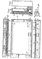
- FIG. 4 shows the magazine 139 in a section transverse to the narrow side of the essentially rectangular magazine.
- a self-contained sound carrier sleeve 140 is rotatably placed over deflection rollers 141 and 142; the Roller 142 is driven by a (not shown) in a T onwieder- display portion of a motor.
- a pressure plate 144 Under a sound head 143 is a pressure plate 144, which are under tension from two leaf springs 145 towards the sound head, so that the sound head can come into operative connection with the sleeve 140.
- the sound head 143 is held in a plastic housing 146 (see also FIG. 6).
- Two ribs 147 serve to guide it in the scanning direction.
- Two contact springs 148 conduct the electrical signals on two busbars 149 and from there to two external contacts 150 which, like the drive, are connected to the recording and reproducing device (not shown).
- the structure of the plastic housing 146 for the sound head 143 can be seen in FIG. 6.
- the housing has the two contact springs 148 and a driver cam 151 which is movable in the vertical direction (in the drawing).
- This cam has two functions: in operative connection with a transport rake 152, it is used to move the sound head to a new track when changing the image and, on the other hand, to return the sound head with its housing to the starting position when the relevant image sequence, which is stored in the magazine, is used once went through.
- FIG 3 shows the mode of operation of the transport rake 152.
- the slide 153 runs onto the nose 154 of the transport rake 152 and pushes it back into a starting position in the magazine housing 155 regardless of the position which it had previously taken.
- the plastic housing 146 for the sound head 143 is taken along the same path by arranged on the transport rake lamella 156, which can evade individually in the manner of leaf springs.
- the rake 152 can dodge, the biasing springs 157 giving way.
- the lamella which lies immediately in front of the cam 151, also springs back because it is displaced by the cam. This slat then takes over the active function, etc.
- Fig. 1 shows the control of the cam 151 for the sound head guide.
- the wedge 158 pushes the cam 151 upwards when it reaches its end position, so that it can be gripped by the tooth 159 of the interchangeable slide 153 and pulled upward with it.
- the wedge 160 presses the cam 151 down again.
- Fig. 2 shows the components installed in the cassette base 161, in particular the sleeve 140
- Fig. 5 shows the front view of the slide 153, the wall of which, when closed, covers the card storage compartment 162 and the audio sleeve part of the magazine.
- the wedge 158 can be designed to be adjustable from the outside, so that the sound head on the cuff, after scanning the sound track assigned to the last card of the card stack, immediately returns to the starting position Scanning the track for the first card being transported.
- the cam 151 is pushed upward at a position lying further inwards and is then gripped by tooth 159 of the interchangeable slide.
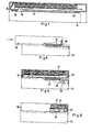
- FIG. 7 to 10 show the arrangement in a second embodiment.
- the bottom of a magazine 86 is coupled to a recording and reproducing device 85 by sliding.
- the coupled state is shown in Fig. 7 in a side view, partially in longitudinal section.
- Fig. 8 shows schematically the process of the clutch.
- a displaceable cover 87 is provided on the underside of the magazine 86 and meets a stop cam 88 when the magazine is pushed onto a sliding guide of the device 85.
- the two parts finally assume the position according to FIG. 9, the cover 87, because it is in contact with the cam 88, displacing relative to the magazine and thus clearing an opening on the underside of the magazine.
- the head 89 of the recording and reproducing apparatus can now be activated by means (not shown), i.e. it is lifted through the opening into the magazine until it resiliently rests on the underside of the bottom card 90 of the stack 91 at the point where the cards have a sound track. Thereafter, the sound head can be moved perpendicular to the plane of the drawing in a manner known per se by uniform movement relative to this sound track, so that the recording or the reproduction can take place approximately according to the magnetic-sound method.
- the sound head 89 here scans the sound track on the bottom card of the stack, while the top card of the stack is presented to the viewer through the window of the magazine, the assignment of image information and sound information is ensured as long as the order of the cards in the magazine remains unchanged and no card is removed or added. Since the sequence of the cards in the magazine is not changed by the change slide actuation, but the cards are only shifted cyclically, the assignment remains unaffected by the change process.
Abstract
Description
Die Erfindung betrifft eine Anordnung zum Betrachten von Bildkarten und koordinierten Aufzeichnen und/oder Abspielen von Toninformationen.The invention relates to an arrangement for viewing picture cards and coordinated recording and / or playing sound information.
Eine Anordnung mit den im Oberbegriff des Patentanspruchs 1 genannten Merkmalen ist in der DE-PS 22 19 865 beschrieben und dargestellt. Bei dieser bekannten Anordnung sind die nacheinander zu präsentierenden Bildinformationen (nachstehend kurz "Bilder") kettenartig fest miteinander verbunden, und die jeweils den Bildern zugeordneten Tonaufzeichnungen sind als Tonspuren auf einer, jeweils einer Anzahl von Bildern gemeinsam zugeordneten Tonbandmanschette nebeneinander vorgesehen. Bei Fortschaltung der Bilderkette um ein Bild wird synchron ein Tonkopf um eine Spurbreite von der zuletzt abgetasteten Spur auf der Manschette auf die nächste Spur geschaltet. Da die Anzahl der auf einer Manschette unterbringbaren Spuren begrenzt ist, wird auch die Zahl der Bilder in der Kette begrenzt, und jeweils eine so zusamengestellte "Tonbildschau" ist in einem gemeinsamen Gehäuse untergebracht, das in einen Diapositivprojektor einsetzbar ist.An arrangement with the features mentioned in the preamble of claim 1 is described and shown in DE-PS 22 19 865. In this known arrangement, the image information to be presented one after the other (hereinafter referred to as "images") is firmly connected to one another in a chain-like manner, and the sound recordings assigned to the images are provided next to one another as audio tracks on a tape cuff, each assigned to a number of images. When the picture chain is advanced by one picture, a sound head is switched synchronously by one track width from the last scanned track on the cuff to the next track. Since the number of tracks that can be accommodated on a cuff is limited, the number of images in the chain is also limited, and a “sound image show” thus composed is accommodated in a common housing which can be used in a slide projector.
Diese bekannte Anordnung ist für die vorgegebenen Progranme geeignet, bei denen von vornherein feststeht, in welcher Reihenfolge die einzelnen Bilder aufeinanderfolgen, so daß in analogen Reihenfolgen auch die Toninformationen auf den Spuren aufgezeichnet werden.This known arrangement is suitable for the predetermined programs, in which it is clear from the start in what order the individual images follow one another, so that the sound information is also recorded on the tracks in analog orders.
Ein Amateur erhält von der Ropieranstalt aber Negativ-oder Diapositivstreifen, auf denen die Bilder in ungeordneter Folge einschließlich unbrauchbarer Aufnahmen miteinander verbunden werden. Um eine Vertonung und eine Vorführung mit einer eingangs erwähnten Anordnung vornehmen zu können, müßte er zuerst einmal die Streifen in Einzelbilder zerlegen, in eine gewünschte Ordnung bringen, wieder zu einem Streifen fest zusammenfügenetwa durch Verkleben - und könnte dann mit der Vertonung beginnen. Stellt sich bei der Vertonung heraus, daß doch eine andere Reihenfolge besser gewesen wäre, muß er ezneut schneiden und kleben. Deshalb ist die bekannte Anordnung für den Amateur praktisch nicht brauchbar. Für Fotoposi tive ist das Aneinanderkleben zu Ketten vollends ungeeignet, so daß für die am weitesten verbreitete Form des Bildträgers, die allein eine unmittelbare Betrachtung ohne Projektor zuläßt, die bekannte Anordnung von vornherein ausscheidet.However, an amateur receives negative or slide strips from the Ropieranstalt, on which the pictures are connected to one another in a disordered sequence, including unusable pictures. In order to be able to perform a soundtrack and a demonstration with the arrangement mentioned at the beginning, he would first have to split the stripes into individual pictures, arrange them in the desired order, put them back together to form a stripe, for example by gluing - and could then start the soundtrack. If it turns out in the setting that a different order would have been better, he has to cut and glue again. Therefore, the known arrangement is practically unusable for the amateur. For Fotoposi tive sticking to chains is completely unsuitable, so that for the most widespread form of the image carrier, which only allows direct viewing without a projector, the known arrangement eliminates from the outset.
Aufgabe der Erfindung ist es, eine Anordnung mit den im Oberbegriff des Patentanspruchs 1 genannten Merkmalen zu schaffen, bei der lose Fotopositive oder allgemein Papierbilder in eine beliebige Reihenfolge geordnet werden können, ohne sie jedoch miteinander zu verbinden, wonach sie nacheinander vertont werden können und bei Betrachtung der Bilder der zu jedem Bild aufgezeichnete Ton wieder abspielbar ist, ohne daß der Zuordnung von Bild und Ton noch Aufmerksamkeit geschenkt zu werden braucht.The object of the invention is to provide an arrangement with the features mentioned in the preamble of claim 1, in which loose photo positives or generally paper pictures can be arranged in any order, but without connecting them, after which they can be set to each other and at Viewing the images, the sound recorded for each image can be played again without paying any attention to the assignment of image and sound.
Die Lösung dieser Aufgabe ergibt sich durch die im kennzeichnenden Teil des Patentanspruchs 1 genannten Merkmale.This object is achieved by the features mentioned in the characterizing part of patent claim 1.
Wenn demgemäß die gewünschte Reihenfolge der losen Bilder einmal hergestellt ist, werden die Bilder in das Magazin eingefüllt. Bei Betätigung des Wechselschiebers wird das jeweils zur Betrachtung präsentierte Bild gegen ein anderes aus dem Stapel ausgewechselt, wobei zwar alle Bilder nacheinander betrachtet werden können, aber die Reihenfolge aufrechterhalten bleibt, da die Umschichtung des Stapels zyklisch erfolgt. Will man aber an der Reihenfolge doch etwas ändern, so ist dies gleichwohl möglich, da die Bilder ja lose bleiben. Die prinzipielle Bauweise solcher Wechselmagazine ist bekannt.Accordingly, once the desired order of the loose images is established, the images are filled into the magazine. When the slide switch is actuated, the image presented for viewing is exchanged for another image from the stack, although all images can be viewed one after the other, but the Sequence is maintained since the stack is rearranged cyclically. But if you want to change something in the order, this is still possible, since the pictures remain loose. The basic design of such change magazines is known.
In dem Magazin ist auch der Tonträger untergebracht, beispielsweise in Form einer Magnetbandmanschette. Die Zahl der Tonspuren auf dem Träger ist gleich der maximal in dem Magazin unterbringbaren Bilderzahl, und bei jeder Wechselschieberbewegung wird sowohl ein Bild gewechselt als auch eine neue Tonspur gewählt, die dann je nach Bauart der Anordnung ein- oder mehrmals abspielbar ist. Die Synchronisierung oder, genauer gesagt, die Zuordnung von zusammengehöriger Bild- und Tcnaufzeichnung erfolgt ausschließlich durch die Betätigung des Wechselschiebers.The sound carrier is also housed in the magazine, for example in the form of a magnetic tape cuff. The number of audio tracks on the carrier is equal to the maximum number of images that can be accommodated in the magazine, and each time a slide switch movement, an image is changed and a new audio track is selected, which can then be played one or more times depending on the type of arrangement. The synchronization or, more precisely, the assignment of associated image and sound recording is carried out exclusively by actuating the change slide.
Es sei noch angemerkt, daß auch Systeme zum Vertonen von Papierbildern bekannt sind (DE-OS 25 07 269). Bei diesen wird aber ein Tonträger unmittelbar mit dem betreffenden Bild verbunden, was, wenn es rationell geschehen soll, bereits in der Kopieranstalt erfolgen müßte, so daß die dort installierten Anlagen geändert oder ergänzt werden müßten. Ferner ist die Tonspeicherkapazität durch die Tonträgerabmessungen begrenzt, die einer Abmessung des Bildes gleich oder kleiner sein werden. Da schließlich das Bild zur Betrachtung stillstehen muß, erfolgt die für Tonaufzeichnung und -wiedergabe erforderliche Relativbewegung von Tonspur und Tonkopf durch Linearbewegung des Tonkopfes, was zu komplizierten Apparaten führt.It should also be noted that systems are also known for the voicing of paper images (DE-OS 25 07 269). In these, however, a sound carrier is directly connected to the picture in question, which, if it is to be done rationally, would have to be done in the copy facility so that the systems installed there would have to be changed or supplemented. Furthermore, the sound storage capacity is limited by the dimensions of the sound carrier, which will be equal to or smaller than a dimension of the image. Finally, since the picture has to stand still for viewing, the relative movement of the sound track and the sound head required for sound recording and reproduction takes place by linear movement of the sound head, which leads to complicated apparatus.
Das Magazin mit Wechselschieber, das zu der erfindungsgemäßen Anordnung gehört enthält den Tonträger und wird, entweder leer direkt dem Verbraucher oder mit frisch kopierten Abzügen gleich von der Kopieranstalt ausgeliefert. An den Bildern selbst brauchen keinerlei Manipulationen vorgenommen zu werden, so daß auch bisher "stumme" Bilder aus Archivbeständen vertont werden können.The magazine with interchangeable slide, which belongs to the arrangement according to the invention, contains the sound carrier and is delivered either empty directly to the consumer or with freshly copied prints directly from the copier. No manipulation of the images themselves is necessary, so that previously "silent" images from archive stocks can also be set to music.
Im Prinzip ist es für das Funktionieren der Anordnung gemäß der Erfindung unerheblich, wo in dem Magazin der Bilderstapel und der Tonträger untergebracht sind. Die konstruktive Lösung wird jedoch vereinfacht, wenn der Stapel über dem Tonträger angeordnet wird, und wenn die AuBenabmessungen des Magazins hinsichtlich Länge und Breite durch die Bildabmessungen und in der Tiefe durch die Dicke des Stapels und den für den Tonträger benötigten Platz festgelegt werden.In principle, it is irrelevant for the functioning of the arrangement according to the invention where the stack of images and the sound carrier are accommodated in the magazine. However, the constructive solution is simplified if the stack is placed over the sound carrier and if the outside dimensions of the magazine with regard to length and width by the image dimensions and depth by the thickness of the stack and the space required for the sound carrier.
Das Aufzeichnungs- und Wiedergabegerät kann in das Magazin selbst vollständig eingebaut sein, teilweise in das Magazin eingebaut sein und mit einem äußeren Teil verbunden sein, oder aber alle zu dem Aufzeichnungs- und Wiedergabevorgang benötigten Teile außer dem Tonträger selbst können in einem äuBeren Gerät untergebracht sein, mit dem das Magazin durch Einschieben, Aufstecken oder in anderer Weise kuppelbar ist.The recording and reproducing device can be completely built into the magazine itself, partly built into the magazine and connected to an outer part, or all parts required for the recording and reproducing process, apart from the sound carrier itself, can be accommodated in an external device with which the magazine can be coupled by pushing it in, plugging it on or in some other way.
Für die Ausbildung des Tonträgers gibt es unter Verwendung aller Tonaufzeichnungsverfahren verschiedene Möglichkeiten. Der Tonträger kann als Platte oder als Streifen unmittelbar im Magazin befestigt sein. In diesem Falle muß ein Abtastsystem, beispielsweise ein Tonkopf, relativ zu der ortsfesten Platte oder dem ortsfesten Streifen sowohl in Abtastrichtung als auch in Spurwechselrichtung beweglich sein, was einen relativ großen Platz für die Bewegung des Abtastsystems bedingt. Wenn das Abtastsystem außerhalb des Magazins in dem Aufzeichnungs- und Wiedergabegerät angeordnet ist, hat dann das Magazin eine relativ große öffnung, die wieder für den Schutz des Tonträgers nach Entnehmen des Magazins aus dem Gerät durch einen Deckel verschlossen wird.There are various possibilities for the formation of the sound carrier using all sound recording methods. The sound carrier can be attached directly in the magazine as a plate or as a strip. In this case, a scanning system, for example a sound head, must be movable relative to the fixed disk or strip in both the scanning direction and the track changing direction, which requires a relatively large space for the movement of the scanning system. If the scanning system is arranged outside the magazine in the recording and reproducing device, the magazine then has a relatively large opening, which is closed again by a cover for the protection of the sound carrier after the magazine has been removed from the device.
Man kann auch umlaufende Tonträger vorsehen in Form eines Bandes, einer Walze, einer Scheibe oder einer Manschette. Durch den Umlauf des Tonträgers wird entweder die Relativbewegung zwischen Abtastsystem und Tonträger für Aufzeichnung und Wiedergabe oder aber für den Spurwechsel herbeigeführt. Bei Unlauf in Aufzeichnungs- und Wiedergaberichtung kann man eine Tonaufzeichnung endlos abspielen. In jedem Fall muB das Anwählen der neuen Spur zusammen mit dem Bildwechsel erfolgen. Dies erfolgt beispielsweise durch mechanische Kopplung des Schiebers mit einem Spurwechselmechanismus derart, daß bei der Hin- und Herbewegung des Wechselschiebers die Spur um eine Spurbreite weitergeschaltet wird.You can also provide circumferential sound carriers in the form of a tape, a roller, a disc or a cuff. Through the circulation of the sound carrier, either the relative movement between the scanning system and the sound carrier for recording and playback or for changing lanes is brought about. If the recording and playback direction is not running, a sound recording can be played back endlessly. In any case, the new track must be selected together with the picture change. This is done, for example, by mechanically coupling the slide to a lane change mechanism in such a way that the track is switched by one track width when the change slide moves back and forth.
Damit der Benutzer flexibel ist in der Festlegung der Zahl von Bildern, die er in einem Magazin zusammenfassen und vertonen möchte, ist vorzugsweise der Spurwechselmechanismus so ausgelegt, daß die Rückstellung auf die erste Spur ebenfalls durch die Betätigung des Wechselschiebers an einer wählbaren Position erfolgt, die ihrerseits eingestellt wird, je nach der Zahl der im Magazin befindlichen Bilder. Es ist sowohl möglich, den Spurwechsel dadurch zu bewirken, daß das Abtastsystem relativ zu einem Tonträger von Spur zu Spur versetzt wird, als auch dadurch, daß der Tonträger selbst relativ zu dem feststehenden Abtastsystem um eine Spurbreite versetzt wird. Dies ist auch dann möglich, wenn der Tonträger selbst umlaufend ausgebildet ist. Beispielsweise kann bei einer Manschette als Tonträger die Anordnung der Spuren nebeneinander quer zur Umlaufrichtung vorgesehen sein und der Tonkopf wird spurweise relativ zur Manschettenbreite versetzt. Eine Manschette kann aber auch so angeordnet werden, daß sie quer zu ihrer Umlaufrichtung vom Tonkopf abgetastet wird und jeweils schrittweise weitergedreht wird, wenn ein Spurwechsel erfolgen sollte.So that the user is flexible in determining the number of images that he wants to summarize and set to music in a magazine, the lane change mechanism is preferably so placed that the return to the first track is also done by operating the slide switch at a selectable position, which in turn is set, depending on the number of images in the magazine. It is possible to effect the track change by shifting the scanning system relative to a sound carrier from track to track, as well as by shifting the sound carrier itself by one track width relative to the fixed scanning system. This is also possible if the sound carrier itself is circumferential. For example, in the case of a cuff as a sound carrier, the tracks can be arranged next to one another transversely to the direction of rotation and the track head is offset in tracks relative to the cuff width. However, a cuff can also be arranged in such a way that it is scanned across the direction of rotation by the sound head and is rotated step by step if a lane change should take place.
Wenn ein Teil oder alle Aufzeichnungs- und Wiedergabekanponenten für die Toninformation in einem mit dem Magazin kuppelbaren Gerät untergebracht sind, weist das Magazin vorteilhafterweise eine Öffnung auf, durch die der Zugang zur Tonspur für Aufzeichnung oder Wiedergabe erfolgt. Aus Gründen der Aufrechterhaltung des Staubschutzes und auch aus ästhetischen Gründen, wird eine solche Öffnung, wenn das Magazin von dem Gerät entkuppelt wird, wieder verschlossen, z.B. dnrch einen Klapp- oder Schiebedeckel. Konstruktiv ist dafür zu sorgen, daß nicht nur die Ausfluchtung des Tonkopfes mit der jeweiligen Tonspur durch den Kopplungsvorgang sichergestellt sein muß, wobei vorteilhafterweise einrastende Verriegelungen oder dergleichen vorgesehen werden, sondern man muß auch dafür sorgen, daß das Magazin einerseits, aber auch das Gerät selbst andererseits so ausgebildet sein müssen, daß auch bei mit dem Gerät gekuppelten Magazinen die ganze Anordnung funktionsfähig ist, und zwar auch für den Bildwechsel, d.h. daß der Wechselschieber frei beweglich bleibt und auch frei erfaßt werden kann.If part or all of the recording and reproducing components for the sound information are accommodated in a device which can be coupled to the magazine, the magazine advantageously has an opening through which access to the sound track for recording or reproduction takes place. For reasons of maintaining dust protection and also for aesthetic reasons, such an opening is closed again when the magazine is uncoupled from the device, e.g. through a hinged or sliding lid. Design must ensure that not only the alignment of the sound head with the respective sound track must be ensured by the coupling process, advantageously locking latches or the like are provided, but you also have to ensure that the magazine on the one hand, but also the device itself on the other hand, must be designed so that the entire arrangement is functional even with magazines coupled to the device, and also for the image change, ie that the change slide remains free to move and can also be freely detected.
Es ist auch möglich, insbesondere für die Wiedergabe von Bild- und Toninformationen für ein größeres Publikum, unmittelbar aus den Magazinen heraus die Bilder zu projizieren und die zugehörigen Toninformationen abzuspielen, wofür das Tonwiedergabegerät zugleich als Projektionsapparat für die Bildinformation ausgebildet ist. Wenn für das Aufzeichnungs- und Wiedergabegerät größere Abmessungen zulässig sind, beispielsweise bei der letztgenannten Kombination mit einer Bildprojektionsoptik, kann man auch einen motorischen Antrieb für den Wechselschieber vorsehen, welcher Antrieb durch Tastendruck betätigbar ist. Mit der Wechselbewegung erfolgt dann immer auch der Übergang auf die dem projizierten Bild zugeordnete Tonspur. Bei einem motorischen Antrieb des Bildwechselschiebers kann auf der jeweiligen Tonaufzeichnungsspur, wenn etwa das Ende der zu einem projizierten Bild gehörigen Tonaufzeichnung erreicht ist, ein Steuersignal in einem unhörbaren Frequenzbereich aufgezeichnet sein, das dann die Bildwechselbewegung auslöst, um z.B. die vollautomatische und fortlaufende Vorführung einer Ton-und Bildschau zu ermöglichen. Dies ist beispielsweise zweckmäßig bei Vorträgen oder Werbeveranstaltungen.It is also possible, particularly for the reproduction of picture and sound information for a larger audience, to project the pictures directly from the magazines and to play the associated sound information, for which the sound reproduction device is also designed as a projection apparatus for the image information. If larger dimensions are permissible for the recording and reproducing device, for example in the latter combination with image projection optics, a motor drive for the change slide can also be provided, which drive can be actuated by pressing a button. With the alternating movement, the transition to the sound track assigned to the projected image then always takes place. With a motorized drive of the image change slider, a control signal in an inaudible frequency range can be recorded on the respective sound recording track, for example when the end of the sound recording associated with a projected image, which then triggers the image change movement, for example for the fully automatic and continuous presentation of a sound and to enable image viewing. This is useful, for example, for lectures or advertising events.
Die folgenden Erläuterungen beziehen sich vor allem auf die Magnet-Ton-Aufzeichnung, und die dort gebräuchlichen Ausdrücke werden verwendet, doch versteht es sich, daß die analogen Betrachtungen auch für andere Aufzeichnungs- und Wiedergabeverfahren in jeweils analoger Weise gelten, beispielsweise für Licht-Ton-Aufzeichnungen.The following explanations relate primarily to magnetic sound recording, and the terms used there are used, but it is understood that the analog considerations also apply in an analogous manner to other recording and reproduction methods, for example to light sound -Records.
Beim Magnet-Ton-Verfahren ist für die Aufzeichnung und Wiedergabe eine Relativbewegung zwischen dem Tonträger und dem Tonkopf erforderlich, wobei der Tonkopf mit einer gewissen Kraft an der Magnetspur anliegen soll, und für den Übergang von Spur zu Spur ist eine Relativbewegung quer zu der Aufzeichnungs- und Wiedergabebewegung erforderlich. Das Anliegen während des Aufzeichnungs- oder Wiedergabevorgangs soll aber vorteilhafterweise dann unterbrochen wexden, wenn ein Spurwechsel erfolgt. Dies kann ebenfalls von der Schieberbetätigung gesteuert oder bewirkt werden.In the magnetic-sound method, a relative movement between the sound carrier and the sound head is required for the recording and reproduction, the sound head being intended to bear against the magnetic track with a certain force, and for the transition from track to track a relative movement is transverse to the recording - and playback movement required. The concern during the recording or playback process should, however, advantageously be interrupted when a lane change takes place. This can also be controlled or effected by the slide actuation.
Die gleichförmige Aufzeichnungs- bzw. Wiedergaberelativbewegung zwischen Tonträger und Tonkopf und die Rückführung des Tonkopfes in seine Ausgangsstellung, die erforderlich ist, wenn die Spur nicht eine in sich geschlossene Schleife bildet, können in konventioneller Weise elektromotorisch vorgenommen werden. Es ist aber auch möglich, die Rückstellbewegung des Tonkopfes ebenfalls von der Wechselschieberbetätigung des Magazins zu steuern oder direkt zu bewirken. Eine besonders preisgünstige und sehr kompakt herstellbare Ausführungsform ergibt sich, wenn durch die Wechselbewegung des Wechselschiebers ein mechanischer Energiespender, z.B. eine Feder, aufgeladen wird, der dann die Vorschubenergie für die gleichförmige Abtastbewegung des Tonkopfes liefert und gegebenenfalls auch für seine Rückstellung in die Ausgangsposition und/oder den Spurwechsel. Aus anderen Gebieten der Technik sind Hemmwerke bekannt, mittels denen die Energieabgabe eines solchen aufgeladenen Energiespeichers gleichmäßig genug für eine heutigen Qualitätsanforderungen genügende Gleichförmigkeit möglich. Die bei der Wechselbewegung aufbringbare und in dem mechanischen Speicher speicherbare Energie wird im allgemeinen für mehrere Abtast- und Rückstellvorgänge ausreichen. Andernfalls kann man durch Betätigung des Wechselschiebers den Energiespeicher nachladen, wobei jedoch die Wechselbewegung nicht vollständig durchgeführt wird, und damit auch kein Bildwechsel erfolgt. Sowohl bei einem motorischen Tonkopf- bzw. Tonträgerantrieb als auch bei einem Antrieb von einem mechanischen Energiespeicher her kann man unterschiedliche Abtastgeschwindigkeiten vorsehen, um die Aufzeichnungs- und Wiedergabedauer bei gegebener Länge der Magnetaufzeichnungsspur zu verändern, und man kann im Magazin oder auch im Aufzeichntmgs- und Wiedergabegerät eine Anzeige mit Skale für die jeweils noch zur Verfügung stehende Speicherkapazität der Tcnaufzeichnung vorsehen. Wenn der zu bewegende Tonkopf nicht im Magazin selbst, sondern in einem anzukuppelnden Aufzeichnungs-und Wiedergabegerät enthalten ist, kann man gleichwohl einen durch die Wechselschieberbetätigung aufladbaren mechanischen Energiespeicher verwenden, der dann vorzugsweise, aber nicht unbedingt zwingend, in dem Gerät untergebracht ist und mechanisch mit dem Wechselschieber gekoppelt ist.The uniform recording or playback relative movement between the sound carrier and the sound head and the return of the sound head to its starting position, which is necessary if the track does not form a closed loop, can be carried out in a conventional manner by an electric motor. It is but also possible to control the return movement of the sound head also by the slide switch actuation of the magazine or to effect it directly. A particularly inexpensive and very compact embodiment can be obtained when a mechanical energy dispenser, for example a spring, is charged by the alternating movement of the interchangeable slide, which then supplies the feed energy for the uniform scanning movement of the sound head and possibly also for its return to the starting position and / or changing lanes. Inhibitors are known from other fields of technology, by means of which the energy delivery of such a charged energy store is possible in a uniform enough manner for uniformity which is sufficient for today's quality requirements. The energy that can be applied during the alternating movement and that can be stored in the mechanical memory will generally be sufficient for several scanning and resetting processes. Otherwise, the energy store can be recharged by actuating the change slide, but the change movement is not carried out completely, and therefore no picture change takes place. Both with a motorized sound head or sound carrier drive as well as with a drive from a mechanical energy store, different scanning speeds can be provided in order to change the recording and playback duration for a given length of the magnetic recording track, and one can in the magazine or also in the recording and Playback device provide a display with a scale for the still available storage capacity of the recording. If the sound head to be moved is not contained in the magazine itself, but in a recording and reproducing device to be coupled, one can nevertheless use a mechanical energy store which can be charged by the change-over slide actuation and which is then preferably, but not necessarily, accommodated in the device and mechanically the change slide is coupled.
Wie oben angedeutet, kann man auch die für den Spurwechsel erforderliche Bewegungsenergie einem durch die Wechselschieberbetätigung aufgeladenen mechanischen Energiespeicher entnehmen. Ein solcher mechanischer Energiespeicher macht die Anardnung nicht nur preisgünstig, sondern vergrößert auch entsprechend die Lebensdauer von für die elektronische Verstärkung benötigten Batterien, die nicht mehr die Energie für die Tonkopfbewegung und/oder die Spurwechselbewegung zu liefern brauchen.As indicated above, the kinetic energy required for changing lanes can also be obtained from a mechanical energy store charged by the change-over slide actuation. Such a mechanical energy store does not only do the rigging inexpensive, but also correspondingly increases the lifespan of batteries required for electronic amplification, which no longer need to supply the energy for the movement of the head and / or the movement of the lane change.
Zwei Ausführungsformen der Anordnung gemäß der Erfindung werden nachstehend unter Bezugnahme auf die beigefügten Zeichnungen im einzelnen erläutert.Two embodiments of the arrangement according to the invention are explained in detail below with reference to the accompanying drawings.
Fig. 1 bis 6 beziehen sich auf ein erstes Ausführungsbeispiel und Fig. 7 bis 10 auf ein zweites.
- Fig. 1" zeigt ein Magazin der Anordnung im Schnitt parallel zur Bewegung eines Tonkopfes und parallel zur Bewegungsrichtung des Wechselschiebers,
- Fig. 2 zeigt eine Draufsicht auf den Tonträgerspeicher, eingebaut nahe dem Boden des Magazins,
- Fig. 3 ist eine Teilschnittdarstellung ähnlich Fig. 2, jedoch in einer anderen Ebene,
- Fig. 4 ist ein Schnitt quer durch das Magazin,
- Fig. 5 ist eine Frontansicht des geschlossenen Magazins,
- Fig. 6 zeigt perspektivisch den Tonkopf zur Verwendung in dem Magazin nach Fig. 1 bis 5,
- Fig. 7 zeigt in teilgeschnittener Seitenansicht eine zweite Ausführungsform der Anordnung nach der Erfindung,
- Fig. 8 zeigt halbschematisch den Vorgang der Verbindung bei dieser zweiten Ausführungsform in ähnlicher Darstellung wie Fig. 7, und
- Fig. 9 und 10 sind Schnitte in Ebenen parallel zu der der Fig. 8.
- 1 "shows a magazine of the arrangement in section parallel to the movement of a sound head and parallel to the direction of movement of the change slide,
- 2 shows a plan view of the sound carrier memory, installed near the bottom of the magazine,
- 3 is a partial sectional view similar to FIG. 2, but in a different plane,
- 4 is a section across the magazine,
- 5 is a front view of the closed magazine,
- 6 is a perspective view of the head for use in the magazine of FIGS. 1 to 5,
- 7 shows a partially sectioned side view of a second embodiment of the arrangement according to the invention,
- Fig. 8 shows semi-schematically the connection process in this second embodiment in a similar representation as Fig. 7, and
- 9 and 10 are sections in planes parallel to that of FIG. 8.
Bei der Ausführungsform nach Fig. 1 bis 6 weist das Magazin einen für alle eingelegten Karten gemeinsamen Tonspeicher oder Tonträger auf, und ein Tonkopf zur Abtastung des Tonträgers ist in das Magazin eingebaut.In the embodiment according to FIGS. 1 to 6, the magazine has a sound memory or sound carrier common to all inserted cards, and a sound head for scanning the sound carrier is built into the magazine.
In Fig. 4 erkennt man das Magazin 139 in einem Schnitt quer zur Schmalseite des im wesentlichen rechteckigen Magazins. Im Kassettenboden 161 ist eine in sich geschlossene Tonträgermanschette 140 drehbar über Umlenkwalzen 141 und 142 gelegt; die Walze 142 wird von einem in einem (nicht dargestellten) Tonwieder- gabeteil aus motorisch angetrieben.4 shows the
Unter einem Tonkopf 143 liegt eine Andruckplatte 144, die von zwei Blattfedern 145 auf den Tonkopf zu unter Vorspannung stehen, so daß der Tonkopf in Wirkverbindung mit der Manschette 140 treten kann.Under a
Der Tonkopf 143 ist in einem Kunststoffgehäuse 146 (siehe auch Fig. 6) gehalten. Zwei Rippen 147 dienen seiner Führung in der Abtastrichtung. Zwei Kontaktfedern 148 leiten die elektrischen Signale auf zwei Stromschienen 149 und von dort auf zwei AuBenkontakte 150, die wie der Antrieb mit dem nicht dargestellten Aufzeichnungs- und Wiedergabegerät verbunden sind.The
Man erkennt in Fig. 6 den Aufbau im einzelnen des Kunststoffgehäuses 146 für den Tonkopf 143. Das Gehäuse weist die beiden Kontaktfedern 148 sowie einen in Vertikalrichtung (in der Zeichnung) beweglichen Mitnehmernocken 151 auf. Dieser Nocken hat zwei Aufgaben: Er dient in Wirkverbindung mit einem Transportrechen 152 für das Versetzen des Tonkopfes auf eine neue Spur beim Bildwechsel und andererseits der Rückführung des Tonkopfes mit seinem Gehäuse in die Ausgangsstellung, wenn die betreffende Bildfolge, die im Magazin gespeichert ist, einmal durchgelaufen ist.The structure of the
Fig. 3 läßt die Arbeitsweise des Transportrechens 152 erkennen. Bei jedem Rückhub des Wechselschiebers 153 in das Magazingehäuse hinein läuft der Schieber 153 auf die Nase 154 des Transportrechens 152 auf und stößt diesen unabhängig von der Stellung, die er vorher eingencomme hatte, wieder in eine Ausgangsposition im Magazingehäuse 155 hinein. Das Kunststoff gehäuse 146 für den Tonkopf 143 wird dabei um den gleichen Weg von an dem Transportrechen angeordneten Lamellen 156 mitgenommen, die einzeln nach Art von Blattfedern ausweichen können. Beim Wiederherausziehen des Wechselschiebers 153 kann der Rechen 152 ausweichen, wobei die Vorspannfedern 157 nachgeben. Die Lamelle, die unmittelbar vor dem Nocken 151 liegt, federt ebenfalls zurück, weil sie durch den Nocken verdrängt wird. Diese Lamelle übernimmt dann neu die aktive Funktion, usw.3 shows the mode of operation of the
Fig. 1 läßt die Steuerung des Nockens 151 für die Tonkopfführung erkennen. Durch den Keil 158 wird der Nocken 151 bei Erreichen seiner Endposition nach oben geschoben, so daß er vom Zahn 159 des Wechselschiebers 153 erfaßt und mit nach oben gezogen werden kann. Damit er von dieser Ausgangslage ausgehend erneut mit dem Transportrechen 152 zusammenwirken kann, drückt der Keil 160 den Nocken 151 wieder nach unten.Fig. 1 shows the control of the
Fig. 2 läßt die im Kassettenboden 161 eingebauten Komponenten, insbesondere die Manschette 140, erkennen, während Fig. 5 die Frontansicht des Schiebers 153 zeigt, dessen Wandung bei geschlossenem Zustand das Kartenaufbewahrungsabteil 162 und den Tonmanschettenteil des Magazins abdeckt.Fig. 2 shows the components installed in the
Wenn das Magazin nicht ganz gefüllt ist, d.h. weniger Karten enthält als dem Tonkopf 143 Tonspuren auf der Manschette zugeordnet sind, so kann man den Keil 158 von außen her verstellbar ausbilden, so daß der Tonkopf nach Abtastung der der letzten Karte des Kartenstapels zugeordneten Tonspur auf der Manschette sofort wieder in die Ausgangsposition zurück zur Abtastung der Spur für die erste Karte transportiert wird. Der Nocken 151 wird dabei an einer weiter innen liegenden Position nach oben geschoben und dann von Zahn 159 des Wechselschiebers erfaßt.If the magazine is not completely full, i.e. Fewer cards contain than 143 sound tracks on the cuff are assigned to the sound head, so the
Die Fig. 7 bis 10 zeigen die Anordnung in einer zweiten Ausführungsform. Bei dieser Ausführungsform wird die Unterseite eines Magazins 86 mit einem Aufzeichnungs- und Wiedergabegerät 85 durch Aufschieben gekuppelt. Der gekuppelte Zustand ist in Fig. 7 in Seitenansicht, teilweise im Längsschnitt, dargestellt.7 to 10 show the arrangement in a second embodiment. In this embodiment, the bottom of a
Fig. 8 läßt schematisch den Vorgang bei der Kupplung erkennen. Auf der Unterseite des Magazins 86 ist ein verschieblicher Deckel 87 vorgesehen, der beim Aufschieben des Magazins auf eine Schiebeführung des Geräts 85 auf einen Anschlagnocken 88 trifft. Bei Fortsetzung des Aufschiebevorgangs nehmen die beiden Teile schließlich die Position gemäß Fig. 9 ein, wobei der Deckel 87, weil er an dem Nocken 88 ansteht, sich relativ zu dem Magazin verschiebt und damit eine Öffnung an der Unterseite des Magazins freimacht.Fig. 8 shows schematically the process of the clutch. A
Der Tonkopf 89 des Aufzeichnungs- und Wiedergabegerätes kann nun durch (nicht dargestellte) Mittel aktiviert werden, d.h. er wird durch die Öffnung bis in das Magazin hineingehoben, bis er an der Unterseite der untersten Karte 90 des Stapels 91 an derjenigen Stelle federnd anliegt, wo die Karten eine Tonspur aufweisen. Danach kann der Tonkopf senkrecht zur Zeichnungsebene in an sich bekannter Weise durch gleichförmige Bewegung relativ zu dieser Tonspur bewegt werden, so daß die Aufzeichnung bzw. die Wiedergabe etwa nach dem Magnet-Ton-Verfahren erfolgen kann.The
Da der Tonkopf 89 hier die Tonspur auf der untersten Karte des Stapels abtastet, während dem Betrachter die oberste Karte des Stapels durch das Sichtfenster des Magazins präsentiert wird, ist die Zuordnung von Bildinformation und Toninformation solange gewährleistet, solange die Reihenfolge der Karten im Magazin unverändert bleibt und auch keine Karte entommen oder hinzugefügt wird. Da durch die Wechselschieberbetätigung die Reihenfolge der Karten im Magazin nicht geändert wird, sondern die Karten nur zyklisch umgeschichtet werden, bleibt die Zuordnung von dem Wechselvorgang unberührt.Since the
Claims (45)
Priority Applications (2)
| Application Number | Priority Date | Filing Date | Title |
|---|---|---|---|
| EP83110771A EP0139778A1 (en) | 1983-10-27 | 1983-10-27 | Arrangement for viewing picture cards and for the co-ordinated recording/replay of sound information |
| JP22662184A JPS60125878A (en) | 1983-10-27 | 1984-10-26 | Image display and sound recorder/reconstructor |
Applications Claiming Priority (1)
| Application Number | Priority Date | Filing Date | Title |
|---|---|---|---|
| EP83110771A EP0139778A1 (en) | 1983-10-27 | 1983-10-27 | Arrangement for viewing picture cards and for the co-ordinated recording/replay of sound information |
Publications (1)
| Publication Number | Publication Date |
|---|---|
| EP0139778A1 true EP0139778A1 (en) | 1985-05-08 |
Family
ID=8190781
Family Applications (1)
| Application Number | Title | Priority Date | Filing Date |
|---|---|---|---|
| EP83110771A Withdrawn EP0139778A1 (en) | 1983-10-27 | 1983-10-27 | Arrangement for viewing picture cards and for the co-ordinated recording/replay of sound information |
Country Status (2)
| Country | Link |
|---|---|
| EP (1) | EP0139778A1 (en) |
| JP (1) | JPS60125878A (en) |
Cited By (4)
| Publication number | Priority date | Publication date | Assignee | Title |
|---|---|---|---|---|
| EP0681206A1 (en) * | 1994-05-03 | 1995-11-08 | Eastman Kodak Company | Talking photoalbum |
| GB2390218B (en) * | 2001-03-15 | 2005-05-11 | Ron Hu | Picture changer with recording and playback capability |
| US6990293B2 (en) | 2001-03-15 | 2006-01-24 | Ron Hu | Picture changer with recording and playback capability |
| CN113168779A (en) * | 2019-11-05 | 2021-07-23 | 山东英才学院 | Split type early education machine for assisting children in learning things |
Citations (9)
| Publication number | Priority date | Publication date | Assignee | Title |
|---|---|---|---|---|
| US3296925A (en) * | 1962-10-26 | 1967-01-10 | Matsushita Electric Ind Co Ltd | Picture projecting and sound record reproducing magazines |
| US3563644A (en) * | 1969-05-12 | 1971-02-16 | Kalart Co Inc | Sound slide projector system |
| DE2219865A1 (en) * | 1971-04-23 | 1972-11-09 | Staar Development Co. S.A., Brüssel | Slide carriers with additional devices for sound recording and devices for audio-visual reproduction |
| US3704337A (en) * | 1969-04-07 | 1972-11-28 | Information Transfer Corp | Tactile response teaching system |
| DE2352001A1 (en) * | 1973-10-17 | 1975-05-07 | Prontor Werk Gauthier Gmbh | Audio-visual equipment for different cassettes - is fitted with simple cam selector for single or double sound track |
| US3883238A (en) * | 1973-12-26 | 1975-05-13 | Panayotis C Dimitracopoulos | Audiovisual slides and apparatus |
| US3997917A (en) * | 1974-04-01 | 1976-12-14 | Sony Corporation | Card handling apparatus |
| US4072989A (en) * | 1976-01-07 | 1978-02-07 | Minnesota Mining And Manufacturing Company | Audio-visual presentation device |
| US4245417A (en) * | 1977-09-20 | 1981-01-20 | Licinvest Ag | Picture viewer |
-
1983
- 1983-10-27 EP EP83110771A patent/EP0139778A1/en not_active Withdrawn
-
1984
- 1984-10-26 JP JP22662184A patent/JPS60125878A/en active Pending
Patent Citations (9)
| Publication number | Priority date | Publication date | Assignee | Title |
|---|---|---|---|---|
| US3296925A (en) * | 1962-10-26 | 1967-01-10 | Matsushita Electric Ind Co Ltd | Picture projecting and sound record reproducing magazines |
| US3704337A (en) * | 1969-04-07 | 1972-11-28 | Information Transfer Corp | Tactile response teaching system |
| US3563644A (en) * | 1969-05-12 | 1971-02-16 | Kalart Co Inc | Sound slide projector system |
| DE2219865A1 (en) * | 1971-04-23 | 1972-11-09 | Staar Development Co. S.A., Brüssel | Slide carriers with additional devices for sound recording and devices for audio-visual reproduction |
| DE2352001A1 (en) * | 1973-10-17 | 1975-05-07 | Prontor Werk Gauthier Gmbh | Audio-visual equipment for different cassettes - is fitted with simple cam selector for single or double sound track |
| US3883238A (en) * | 1973-12-26 | 1975-05-13 | Panayotis C Dimitracopoulos | Audiovisual slides and apparatus |
| US3997917A (en) * | 1974-04-01 | 1976-12-14 | Sony Corporation | Card handling apparatus |
| US4072989A (en) * | 1976-01-07 | 1978-02-07 | Minnesota Mining And Manufacturing Company | Audio-visual presentation device |
| US4245417A (en) * | 1977-09-20 | 1981-01-20 | Licinvest Ag | Picture viewer |
Cited By (6)
| Publication number | Priority date | Publication date | Assignee | Title |
|---|---|---|---|---|
| EP0681206A1 (en) * | 1994-05-03 | 1995-11-08 | Eastman Kodak Company | Talking photoalbum |
| US5574519A (en) * | 1994-05-03 | 1996-11-12 | Eastman Kodak Company | Talking photoalbum |
| GB2390218B (en) * | 2001-03-15 | 2005-05-11 | Ron Hu | Picture changer with recording and playback capability |
| US6990293B2 (en) | 2001-03-15 | 2006-01-24 | Ron Hu | Picture changer with recording and playback capability |
| CN113168779A (en) * | 2019-11-05 | 2021-07-23 | 山东英才学院 | Split type early education machine for assisting children in learning things |
| CN113168779B (en) * | 2019-11-05 | 2022-06-28 | 温州大学 | Split type early education machine for assisting children to learn things |
Also Published As
| Publication number | Publication date |
|---|---|
| JPS60125878A (en) | 1985-07-05 |
Similar Documents
| Publication | Publication Date | Title |
|---|---|---|
| DE3006735C2 (en) | Video signal recording and / or reproducing apparatus | |
| DE1190691B (en) | Magnetic tape device with several interchangeable cassettes | |
| DE3239659C2 (en) | ||
| DE1522984A1 (en) | Tape recording and playback apparatus and dedicated tape cartridge | |
| DE1229750B (en) | Sound and image playback device and sound image carrier for use with such a device | |
| DE3645073C2 (en) | ||
| DE1762641B2 (en) | ARRANGEMENT FOR RECORDING AND / OR REPLAYING VIDEO SIGNALS | |
| DE2324657A1 (en) | TAPE CASSETTE FOR HIGH TAPE SPEED | |
| EP0139778A1 (en) | Arrangement for viewing picture cards and for the co-ordinated recording/replay of sound information | |
| EP0139779A1 (en) | Picture viewing and sound record/playback arrangement | |
| DE2021135C3 (en) | Apparatus for magnetically recording and reproducing information | |
| DE2347668C2 (en) | Cinematographic device, in particular a sound film camera | |
| DE3021751C2 (en) | Device for loading and unloading cassettes from video recorders | |
| DE4032957A1 (en) | VIDEO RECORDS WITH SEVERAL INSTALLATIONS | |
| EP0009673B1 (en) | Recording and/or reproducing apparatus for information carriers provided with a magnetisable area | |
| DE2614745C3 (en) | ||
| DE2053756A1 (en) | Tape recorder | |
| EP0351727B1 (en) | Cassette holder | |
| DE1762990C (en) | Video tape recorder with a housing to which a tape cassette can be detachably connected. Elimination from: 1537240 | |
| DE2462650C2 (en) | Cassette adapter for micro cassettes | |
| DE2653957A1 (en) | AUDIOVISUAL DEVICE | |
| DE1943052A1 (en) | Projector for fixed images with sound reproduction | |
| AT271937B (en) | Tape recorder | |
| DE1041529B (en) | Arrangement for magnetic information storage | |
| DE3603921C2 (en) |
Legal Events
| Date | Code | Title | Description |
|---|---|---|---|
| PUAI | Public reference made under article 153(3) epc to a published international application that has entered the european phase |
Free format text: ORIGINAL CODE: 0009012 |
|
| AK | Designated contracting states |
Designated state(s): AT BE CH DE FR GB IT LI LU NL SE |
|
| 17P | Request for examination filed |
Effective date: 19851003 |
|
| 17Q | First examination report despatched |
Effective date: 19861008 |
|
| STAA | Information on the status of an ep patent application or granted ep patent |
Free format text: STATUS: THE APPLICATION HAS BEEN WITHDRAWN |
|
| 18W | Application withdrawn |
Withdrawal date: 19870204 |
|
| RIN1 | Information on inventor provided before grant (corrected) |
Inventor name: ACKERET, PETER |