EP0139620A2 - Method and apparatus for forming elastic elements under tension from a continuous elastic web, particularly for manufacturing sanitary products such as disposable diapers and the like - Google Patents
Method and apparatus for forming elastic elements under tension from a continuous elastic web, particularly for manufacturing sanitary products such as disposable diapers and the like Download PDFInfo
- Publication number
- EP0139620A2 EP0139620A2 EP84830272A EP84830272A EP0139620A2 EP 0139620 A2 EP0139620 A2 EP 0139620A2 EP 84830272 A EP84830272 A EP 84830272A EP 84830272 A EP84830272 A EP 84830272A EP 0139620 A2 EP0139620 A2 EP 0139620A2
- Authority
- EP
- European Patent Office
- Prior art keywords
- web
- clamping element
- velocity
- drum
- movable
- Prior art date
- Legal status (The legal status is an assumption and is not a legal conclusion. Google has not performed a legal analysis and makes no representation as to the accuracy of the status listed.)
- Granted
Links
Images

Classifications
-
- A—HUMAN NECESSITIES
- A61—MEDICAL OR VETERINARY SCIENCE; HYGIENE
- A61F—FILTERS IMPLANTABLE INTO BLOOD VESSELS; PROSTHESES; DEVICES PROVIDING PATENCY TO, OR PREVENTING COLLAPSING OF, TUBULAR STRUCTURES OF THE BODY, e.g. STENTS; ORTHOPAEDIC, NURSING OR CONTRACEPTIVE DEVICES; FOMENTATION; TREATMENT OR PROTECTION OF EYES OR EARS; BANDAGES, DRESSINGS OR ABSORBENT PADS; FIRST-AID KITS
- A61F13/00—Bandages or dressings; Absorbent pads
- A61F13/15—Absorbent pads, e.g. sanitary towels, swabs or tampons for external or internal application to the body; Supporting or fastening means therefor; Tampon applicators
- A61F13/15577—Apparatus or processes for manufacturing
- A61F13/15585—Apparatus or processes for manufacturing of babies' napkins, e.g. diapers
- A61F13/15593—Apparatus or processes for manufacturing of babies' napkins, e.g. diapers having elastic ribbons fixed thereto; Devices for applying the ribbons
-
- Y—GENERAL TAGGING OF NEW TECHNOLOGICAL DEVELOPMENTS; GENERAL TAGGING OF CROSS-SECTIONAL TECHNOLOGIES SPANNING OVER SEVERAL SECTIONS OF THE IPC; TECHNICAL SUBJECTS COVERED BY FORMER USPC CROSS-REFERENCE ART COLLECTIONS [XRACs] AND DIGESTS
- Y10—TECHNICAL SUBJECTS COVERED BY FORMER USPC
- Y10T—TECHNICAL SUBJECTS COVERED BY FORMER US CLASSIFICATION
- Y10T156/00—Adhesive bonding and miscellaneous chemical manufacture
- Y10T156/12—Surface bonding means and/or assembly means with cutting, punching, piercing, severing or tearing
- Y10T156/1317—Means feeding plural workpieces to be joined
- Y10T156/1322—Severing before bonding or assembling of parts
- Y10T156/133—Delivering cut part to indefinite or running length web
-
- Y—GENERAL TAGGING OF NEW TECHNOLOGICAL DEVELOPMENTS; GENERAL TAGGING OF CROSS-SECTIONAL TECHNOLOGIES SPANNING OVER SEVERAL SECTIONS OF THE IPC; TECHNICAL SUBJECTS COVERED BY FORMER USPC CROSS-REFERENCE ART COLLECTIONS [XRACs] AND DIGESTS
- Y10—TECHNICAL SUBJECTS COVERED BY FORMER USPC
- Y10T—TECHNICAL SUBJECTS COVERED BY FORMER US CLASSIFICATION
- Y10T83/00—Cutting
- Y10T83/04—Processes
- Y10T83/0405—With preparatory or simultaneous ancillary treatment of work
- Y10T83/0419—By distorting within elastic limit
- Y10T83/0424—By stretching
-
- Y—GENERAL TAGGING OF NEW TECHNOLOGICAL DEVELOPMENTS; GENERAL TAGGING OF CROSS-SECTIONAL TECHNOLOGIES SPANNING OVER SEVERAL SECTIONS OF THE IPC; TECHNICAL SUBJECTS COVERED BY FORMER USPC CROSS-REFERENCE ART COLLECTIONS [XRACs] AND DIGESTS
- Y10—TECHNICAL SUBJECTS COVERED BY FORMER USPC
- Y10T—TECHNICAL SUBJECTS COVERED BY FORMER US CLASSIFICATION
- Y10T83/00—Cutting
- Y10T83/202—With product handling means
- Y10T83/2092—Means to move, guide, or permit free fall or flight of product
- Y10T83/2183—Product mover including gripper means
- Y10T83/219—Rotating or oscillating product handler
-
- Y—GENERAL TAGGING OF NEW TECHNOLOGICAL DEVELOPMENTS; GENERAL TAGGING OF CROSS-SECTIONAL TECHNOLOGIES SPANNING OVER SEVERAL SECTIONS OF THE IPC; TECHNICAL SUBJECTS COVERED BY FORMER USPC CROSS-REFERENCE ART COLLECTIONS [XRACs] AND DIGESTS
- Y10—TECHNICAL SUBJECTS COVERED BY FORMER USPC
- Y10T—TECHNICAL SUBJECTS COVERED BY FORMER US CLASSIFICATION
- Y10T83/00—Cutting
- Y10T83/323—With means to stretch work temporarily
-
- Y—GENERAL TAGGING OF NEW TECHNOLOGICAL DEVELOPMENTS; GENERAL TAGGING OF CROSS-SECTIONAL TECHNOLOGIES SPANNING OVER SEVERAL SECTIONS OF THE IPC; TECHNICAL SUBJECTS COVERED BY FORMER USPC CROSS-REFERENCE ART COLLECTIONS [XRACs] AND DIGESTS
- Y10—TECHNICAL SUBJECTS COVERED BY FORMER USPC
- Y10T—TECHNICAL SUBJECTS COVERED BY FORMER US CLASSIFICATION
- Y10T83/00—Cutting
- Y10T83/465—Cutting motion of tool has component in direction of moving work
- Y10T83/4766—Orbital motion of cutting blade
- Y10T83/4795—Rotary tool
- Y10T83/483—With cooperating rotary cutter or backup
Definitions
- the present invention relates to a method for forming elastic elements under tension from a continuous elastic web.
- the invention is preferably applied to the manufacture of sanitary products such as, for example, disposable diapers for infants or incontinent adults.
- tensioned elastic elements are fixed along the longitudinal edges of a sheet of impermeable plastics material which constitutes the outer cover of the product, in order to achieve better adherence of the diaper around a user's legs.
- U.S. Patent No. 4, 081, 301 proposes the uniform stretching of a rubber web, the application of adhesive to discrete lengths of this web, and the sticking of this web to a continuous sheet of impermeable plastics material defining the outer cover of the diaper.
- the web is kept under tension until the adhesive sets and is subsequently cut in the regions free from adhesive. As a result of this cutting, the adhesive-free regions stuck to the sheet of plastics material contract and return to the rest condition.
- U.S. Patent No. 4,297,157 discloses a method in which a continuous elastic web is tensioned and clamped between two jaws spaced by a distance greater than the final length of the elastic element it is wished to form. After the piece of web' between the two jaws is separated from the body of the continuous web, the two jaws are brought closer together until they are at a distance corresponding to the final length. Under these conditions, the piece between the two jaws is stuck to a product such as a disposable diaper.
- the main advantage of this method lies in the fact that, before the elastic element can be brought to the length corresponding to the state of tension in which it is applied to the diaper, it is subjected to an initial intense stretching operation ("over-stretching") whereby it is extended to a length typically twice that for the final application. This operation can compromise the elastic characteristics and the integrity of the elastic element, consequently reducing the production yield.
- the object of the present invention is to provide a method the type specified above, which does not have the disadvantages described previously and which can be carried out economically on an industrial scale.
- this object is achieved by virtue of a process of the type specified, characterised in that it includes the steps of:
- the method according to the invention is characterised in that it includes the steps of:
- a disposable absorbent diaper for infants or incontinent adults is generally indicated 1.
- the diaper 1 is constituted essentially by a sheet 2 of impermeable plastics material, for example a polyethylene film having a thickness of 25 - 30 microns.
- an absorbent body 3 of elongate form constituted by a wad of dry ground cellulose or like material.
- the- absorbent body 3 may however have different shapes from that shown in Figure 1, for example an anatomical shape with end parts which are wider than the central area.
- Two elastic strip elements 4 are glued to the sheet 2 along the longer edges of the absorbent body 3.
- the longer sides of the impermeable sheet 2 have central parts which are curved inwardly and define the so-called leg portions of the-diaper,that is, the portions of the edge which will surround a user's legs.
- the elastic elements 4 are supplied to the impermeable sheet 2 in a state of tension; the resilient contraction force they exert causes the diaper 1 to curve into an anatomical bowl shape which helps the flow of physiological liquids to the absorbent body 3.
- the diaper is secured around the user's waist by interconnecting the shorter sides of the impermeable sheet 2 constituting the outer covering of the diaper at their ends by means of the usual adhesive tabs, indicated 5.
- the absorbent body 3 is normally fixed to the impermeable sheet 2 by a further fluid-permeable covering sheet, indicated 6.
- the covering sheet 6, which is intended to come into contact with the user's skin, is preferably made from a nonwoven fabric so as to minimise the irritation resulting from chafing against the user's skin.
- the elastic elements 4 are fixed to the impermeable body 2 by an adhesive strip of hot-melt material, the setting time of which is quick enough to allow the elastic elements 4 to be applied to the impermeable sheet 2 at the high rate used in industrial production.
- FIGs 2 to 7 illustrate schematically apparatus for use in the formation of elastic elements 4 in the method of manufacture of the diaper of Figure 1.
- a drum, generally indicated 10 is rotated in a clockwise sense by drive means, not illustrated.
- the outer surface of the drum 10, indicated 11, is illustrated schematically in a rectilinear development in Figure 2.
- First jaws 12 for clamping a web 13 of rubber or similar elastic material to the outer surface of the drum are mounted in equiangularly distributed positions on the outer surface 11 of the drum 10.
- the web 13 is supplied continuously to the drum from a supply source illustrated schematically as a group of motor-driven pulleys or rollers, generally indicated 14.
- the velocity at which the web 13 is supplied from the source 14 may be controlled precisely,in the manner which will be explained in greater detail below.
- the jaws 12, of which there are four, are located at 90° to each other around the perimeter of the drum 10 and may be of any known type, for example of the type illustrated in the U.S. Patent No. 4,297,157 mentioned above.
- the jaws 15 are substantially similar to the jaws 12.
- each of the jaws 15 ( Figures 4 to 7) is mounted on a support carriage 16 which can effect a translational movement along the surface 11 of the drum 10 on profiled sliding guides 17 which are typically arcuate and extend tangentially relative to the drum 10 in planes perpendicular to the axis of the drum 10 itself.
- each jaw 15 can effect a translational movement along the surface 11 of the drum 10 between two extreme positions indicated A and B respectively in Figures 2 and 3.
- FIG 2 which, as mentioned above, shows an ideal linear development of the surface of the drum 10
- a jaw 15 in the first position A is shown on the left-hand side
- two jaws 15 in the second position B are shown in the centre
- a jaw 15 which is returning to the first position A from the position B is shown on the right-hand-side.
- each jaw 15 (movable jaw) is immediately behind the jaw 12 (fixed jaw) preceding it in the direction of movement of the surface 11 of the drum 10.
- each movable jaw 15 is in a position intermediate the fixed jaws 12 between which it is positioned.
- the length of the guides 17, that is,the amplitude of the movement of the movable jaws 15 between the first position A and the second position B, is selected so that, in the second position B, the distance between each movable jaw 15 and the fixed jaw 12 which it follows in the direction of movement of the outer surface 11 of the drum 10 is substantially identical to the length of the tensioned elastic elements to be formed.
- the terms "upstream” and “downstream” are used for the relative positions of the jaws 12 and 15 on the surface 11 of the drum 10, with reference to the direction of movement of the surface acting as a support for the formation of the elastic elements 4. More particularly, of two adjacent jaws which pass successively in front of the group of pulleys 14 which supply the web 13, the first jaw is termed the “upstream” jaw while the other jaw is termed the “downstream” jaw. Hence,with reference to the development of Figure 2, each jaw illustrated in this drawing is “upstream” of the jaws to its left and “downstream” of the jaws to its right.
- Each support carriage 16 has a pair of rollers or bearings 18 beneath it which cooperate with the opposite faces of a rib provided on the radially outer face of a drive carriage 19 underlying it (in a radial direction relative to the drum 10).
- This rib indicated 20 in the drawings, has a generally arcuate course which follows the curvature of the drum 10 and extends in a plane inclined at about 45° to the planes containing the guides 17.
- the rib 20 constitutes a ramp part for causing the translational movement of the support carriage 16 along the guides 17 as a result of the translation of the drive carriage 19 axially relative to the drum 10.
- each drive carriage 19 is movable along straight guides 21 which extend axially relative to the drum 10.
- the reference 22 indicates a horizontal-axis drive shaft on which is rigidly keyed a disc 23(or functionally equivalent element such as a ring) supporting the outer surface 11 of the drum 10 on its free edge.
- This surface is normally constituted by a curved sheet-metal plate possibly treated with a non-stick material, such as a silicone rubber, for reasons which will be better explained below.
- the guides 21 extend between the disc or ring (rotor) 23 and the front surface of the drum 10 in correspondence with which the movable jaws 15 and the fixed jaws 12 aligned therewith act.
- the guides 21 are connected by a stiffening element 24 which is also rotated by the shaft 22.
- Two annular elements, indicated 25 and 26, are fitted onto the drive shaft 22 with the interposition of bearings 27 and 28, but are not free to rotate relative to the shaft 22 itself.
- annular elements 25 and 26 which are rigid with each other, are connected by fixing means, not illustrated, to the support frame of the drum 10, schematically indicated H in Figure 3. These are therefore stationary relative to the drum 10 and may act easily as support elements for the shaft 22.
- the annular elements 25 and 26 have profiled peripheral edges which act as operating cams for the jaws 12, 15 and for the carriages 16 supporting the movable jaws 15.
- the operation (opening-closing) of the jaws 12 and 15 is effected by the movement of movable units 29, one of which is illustrated schematically in Figure 4 and each of which has a feeler roller 30 which rolls on the peripheral edge of the annular element 21 against which it is urged by a spring 31.
- each jaw 12, 15 can receive the web 13 supplied from the supply station 14 or, as will be better seen below, allow the removal of a web piece constituting one of the tensioned elastic elements to be formed from the surface of the drum 10.
- the feeler roller is returned to the drum 10 under the action of the spring 31, the corresponding jaw 12, 15 closes to clamp the web 13 onto the surface of the drum 10.
- the peripheral edge of the annular element 25 comprises two consecutive semicircular portions concentric with the drum 10.
- One of these portions, indicated 25a, has a larger radius and extends in correspondence with the lower half of the circular path of movement of the outer surface of the drum 11 between two angular positions schematically indicated o( and ⁇ in Figure 3.
- the other edge portion of the element 25, indicated 25b extends between the angular positions 0( and ⁇ in correspondence with the upper half of the circular path of movement of the surface of the drum 10.
- the rib 32 which extend in continuity with the outer edges of the annular element 26, includes portions disposed in different orthogonal planes to the drive shaft 22 and inclined portions which connect these portions orthogonal to the shaft 22.
- the rib 32 thus constitutes a cam which controls the axial translational movement of the drive carriages 19 along the guides 21,and consequently the translational movement of the carriages 16 supporting the movable jaws l5,between the positions A and B defined above.
- Figure 6 illustrates a situation in which, as a result of the rotation of the drum 10, the rollers: 33,which are only partially visible in the drawing since they are shown in broken outline engage an inclined portion 32b of the rib 32, that is, a portion of the rib 32 which is moving gradually away from the frontal face of the drum 10. Under these conditions, the drive carriage 19 also moves away from the front surface, while the rollers 18 of the support carriage 16 slide along the rib 20 , gradually drawing the support carriage 16 towards the other end position of its translational movement along the guides 17.
- Figure 7 illustrates a situation in which, as a result of the further rotation of the drum 10, the rollers 33 slidingly engage a further portion of the rib 32, 'indicated 32c, which lies in a plane normal to the axis of rotation of the drum.
- the axial position of this plane relative to the drum 10 is such that the drive carriage 19 driven by the rollers 33 is in the position of maximum withdrawal relative to the frontal face of the drum 10.
- rollers 18 have completed their course of sliding movement along the rib 20, carrying the support carriage 10 and the movable jaw 15 mounted thereon into the travel limit position indicated B.
- ⁇ and ⁇ indicate two further angular positions of the path of rotation of the surface of the drum 10. These angular positions are diametrally opposed in a direction perpendicular to the direction of alignment of the angular positions ⁇ and ⁇ previously defined.
- Figure 2 shows approximately the location of the angular position ⁇ in the rectilinear development of the surface of the drum 10.
- the rib 32 provided on the peripheral edge of the tubular element 26 has a profile such that all the support carriages 16 and their movable jaws 15 are in the first position A in correspondence with the angular position ⁇ , and move gradually towards the second position B during the advance from the angular position ⁇ to the angular position o caused by the rotation of the drum 10.
- Two rollers, indicated 34, are located in positions substantially tangential to the roller 20 in correspondence with this path portion.
- the sheet portion 2 between the rollers 34 adheres to the outer surface 11 of the drum 10 and is drawn thereby as a result of the rotation of the drum itself.
- an adhesive for example a hot-melt adhesive, is applied to the sheet 2 so as to form a firm connection between the sheet 2 and the elastic web pieces 13 which are brought into contact therewith in the manner which will be described more fully below.
- the hot-melt adhesive to the sheet is carried out at a spreading station,not shown in the drawings.
- the hot-melt adhesive may be applied to the elastic web 13 by a spreading device which acts on the elastic web 13 adjacent to the angular position
- This spreading device is illustrated schematically in broken outline and indicated S in Figure 3.
- each diaper 1 has two elastic elements 4 disposed parallel to each other on opposite sides of the absorbent body 3, in its application to the manufacture of these products the apparatus according to the invention includes two structures for forming elastic elements which are identical to each other and operate in parallel.
- the apparatus according to the invention includes two structures for forming elastic elements which are identical to each other and operate in parallel.
- the support carriages 16 and the movable jaws 15 mounted thereon are carried gradually towards the first position A.
- the rib 32 acting as an operating cam for the carriages 16 and 19, is profiled so that the carriages 16 and the jaws 15 remain in the position B until the angular position d is reached, and then turn to the first position A during the advance along the arc of the path of movement of the surface of the drum between the angular position or and the angular position ⁇ , returning to the initial conditions described above.
- a cutting element 35 for example a rotary blade, which acts on the elastic web 13 applied to the surface of the drum 10 in correspondence with the angular position ⁇ . More specifically, the cutting element 35 can act on the web portion 13 between each fixed jaw 12 and the movable jaw 15 downstream of this fixed jaw 12, when the two jaws pass through the angular position 0( as a result of the rotation of the drum 10. As indicated above, under these conditions,the movable jaw 15 is in the first position A.
- the cutting member 35 is intended to section the continuous web 13, cutting tensioned web pieces constituting the elastic elements 4 to be applied to the plastics sheet 2 from the continuous body of the web 13.
- the operation of the apparatus according to the invention is effected by rotating of the drum 10 and operating of the supply source for the web 13 (shown schematically as the rollers 14) and the cutting member 35 simultaneously and continuously.
- the rotation of the drum 10 drives the closing and opening of the jaws 12 and 15,and the reciprocating movement of the jaws 15 between the first position A and the second position B, as explained above.
- the drum 10 has a rotational velocity ⁇ 1 such that the outer surface 11 of the drum 10 moves in a clockwise sense with a tangential velocity V 1 .
- the portion of the rib 32 between the angular positions ⁇ and ⁇ , which acts as a drive cam for the carriages 16 on which the jaws 15 are mounted, has a profile such that the translational movement of the jaws 15 between the position A and the positionB is effected at a velocity V 2 (relative to the surface 11 of the drum 10) which is less than the velocity V 1 of advance imparted to the surface itself as a result of the rotation of the drum 10.
- the translational velocity of the jaws 15 from the first position A to the second position B is in the opposite direction from that of the velocity V 1 , as shown schematically by the respective arrows in Figure 2.
- the superposition of the rotational movement of the drum 10 on the movement of the jaws 15 from the first position A to the second position B means that, while the surface 11 of the drum 10 travels with a tangential velocity V 1 through the arc between the angular position ⁇ and the angular position ⁇ , the jaws 15 mounted thereon have a tangential velocity equal to V 1 - V 2 and thus travel only through a part of this arc.
- the value of the velocity V 2 is chosen so that (see Figure 3) each movable jaw 15 reaches the second position B having left the first position A exactly when the fixed jaw 12 located downstream in the direction of advance of the surface of the drum reaches the angular position in which the cutting member 35 acts.
- the second position B of the movable jaws 15 is chosen so that, in this second position, each movable jaw 15 is in a median position relative to the fixed jaws 12 between which it is positioned.
- the profile of the rib 32 is thus selected so that the value of the velocity V 2 is equal to half the value of the tangential velocity V 1 of the surface of the drum 10.
- each movable jaw 15 stops moving translationally relative to the drum 10 and is drawn thereby at the velocity V 1 .
- V 3 With regard to the supply velocity of the web 13 from the source 14, the velocity indicated V 3 , this is chosen so as to be less than the difference between the tangential velocity V 1 of the surface 11 of the drum 10 and the translational velocity V 2 of the jaws 15 from the first position A to the position B.
- This difference (V 1 - V 2 ) determines the velocity at which each movable jaw 12 passes through the initial portion of the arc between the angular positiondand the angular position intermediate the positions ⁇ and ⁇ at which the jaw 15 itself reaches the second position B.
- V 2 is equal to half V 1 whereby this difference is also equal to half V 1 .
- a value of the web supply velocity is chosen to be less than the velocity difference means that the web 13 is applied to the surface of the drum 10 under tension.
- Figure 2 illustrates the relative positions assumed by a movable jaw 15 and the fixed jaw 12 located downstream thereof in the direction of advance of the surface 11 of the drum when the web 13 is clamped in the movable jaw 15 which is located in the first position A in correspondence with the position ⁇ .
- the web piece 13 which is clamped in the movable jaw 15 corresponds,in fact,to the free end of the web 13 itself in that, immediately upstream of the jaw 15, the cutting member 35 cuts the web 13 to separate a piece of web formed previously in the manner which will now be described.
- the movable jaw 15 starts to move on the surface 11 towards the second position B at a velocity V 2 the value of which, as indicated above, is equal to half the value of the tangential velocity V 1 .
- the end of the web 13 clamped in the jaw 15 advances relative to the source 14, which is stationary, at a velocity equal to the difference V 1 - V 2 , that is, at a velocity equal to half V 1 .
- the web 13 is supplied at a velocity equal to a quarter of V 1 , that is, at a velocity less than the difference V 1 - V 2 .
- the web portion 13 between the movable jaw 1 5 and the source 14 is thus stretched longitudinally, which puts it under tension.
- the movable jaw 15 reaches the position B at half the arc of the path between the angular positions ⁇ and ⁇ exactly when the fixed jaw 12 located downstream. thereof reaches the angular position ⁇ together with a further movable jaw 15 which has just returned to the first position A.
- the fixed jaw 12 and the further movable jaw 15 close on the web supplied by the source 14. Between the fixed jaw 12 and the movable jaws 15 located upstream in positions intermediate the positions ⁇ and there is thus formed a tensioned web piece which can be applied to the sheet 2. This piece is separated from the main body of the web 13 by the cutting member 35 which actson the web portion between the fixed jaw 12 and the further movable jaw located immediately downstream.
- the cutting member 35 thus forms a new free end of the web 13 destined to be drawn at the velocity V1 - V 2 by the further movable jaw during the cycle of formation of a new tensioned elastic piece.
- the tensioned elastic piece which has just been formed advances towards the angular position at a tangential velocity V 1 .
- the piece is stuck to the plastics sheets 2 as an elastic element 4 which can confer elasticity and greater adherence to the diaper.
- At least those portions of the surface 11 of the drum 10 for conveying the web pieces 13 are preferably coated with a resilient material, such as a silicone rubber, in order to facilitate the detachment of the sheet 2 carrying the applied elastic elements 4 from the drum 10 itself.
- a resilient material such as a silicone rubber
- the movable jaw 15 In the end part of the path of movement of the surface 11, between the angular position ⁇ and ⁇ , the movable jaw 15 returns to the first position A to receive the web 13 again and to start a new cycle of formation of an elastic element 4.
- a method and apparatus are thus described which allow the rapid formation of tensioned elastic elements, in a manner which can be achieved practically and economically on an industrial scale, it being possible to stick these tensioned elastic elements to a support such as a sheet of impermeable plastics material forming the outer covering of a sanitary product such as a disposable diaper.
- the invention allows the formation of tensioned elastic elements while avoiding the disadvantages typical of the prior art.
- the elastic elements formed according to the invention can be stuck to an inelastic support avoiding the wastage of material resulting from the formation of tails which will return to the rest condition after application.
Landscapes
- Health & Medical Sciences (AREA)
- Engineering & Computer Science (AREA)
- Animal Behavior & Ethology (AREA)
- General Health & Medical Sciences (AREA)
- Biomedical Technology (AREA)
- Heart & Thoracic Surgery (AREA)
- Vascular Medicine (AREA)
- Life Sciences & Earth Sciences (AREA)
- Manufacturing & Machinery (AREA)
- Epidemiology (AREA)
- Public Health (AREA)
- Veterinary Medicine (AREA)
- Absorbent Articles And Supports Therefor (AREA)
- Moulding By Coating Moulds (AREA)
- Golf Clubs (AREA)
- Treatments Of Macromolecular Shaped Articles (AREA)
Abstract
- a relative movement between the supply source (14) and the support (11) in the direction of alignment of the clamping elements (12,15) so as to cause the supply of the continuous web (13) to the fixed clamping element (12);
- the translational movement of the movable clamping element (15) from its first position (A) to its second position (B) at a velocity (V2) less than the velocity (V,) of the relative movement between the web supply source (14) and the support (11), and
- the supply of the web (13) from the source at a velocity (V3) less than the difference (V1-V2) between the velocity (V,) of the relative movement between the source (14) and the support (11) and the velocity (Vz) of the translation of the movable clamping element (15) between the first and second positions (A,B). When the movable clamping element (15) reaches the second position (B), the web (13) is clamped by the fixed clamping element (12) whereby a piece (4) of web extends between the fixed clamping element (12) and the movable clamping element (15) in a state of longitudinal tension the degree of which is determined by the velocity difference (V1-V2) and the supply velocity (V3) of the web (13). Finally, the web (13) is cut in the region between the fixed clamping element (12) and the supply source (14), so as to separate the piece (4) from the body of the web (13) and define one of the tensioned elastic elements, and to form a new free end of the web (13) itself.
Description
- The present invention relates to a method for forming elastic elements under tension from a continuous elastic web.
- The invention is preferably applied to the manufacture of sanitary products such as, for example, disposable diapers for infants or incontinent adults.
- In such diapers, tensioned elastic elements are fixed along the longitudinal edges of a sheet of impermeable plastics material which constitutes the outer cover of the product, in order to achieve better adherence of the diaper around a user's legs.
- Various methods and apparatus are known for forming and applying elastic elements to disposable diapers and like products.
- For example, U.S. Patent No. 4, 081, 301 proposes the uniform stretching of a rubber web, the application of adhesive to discrete lengths of this web, and the sticking of this web to a continuous sheet of impermeable plastics material defining the outer cover of the diaper. The web is kept under tension until the adhesive sets and is subsequently cut in the regions free from adhesive. As a result of this cutting, the adhesive-free regions stuck to the sheet of plastics material contract and return to the rest condition.
- The main disadvantage of this method arises from the fact that the adhesive-free portions of the web are wasted material since they do not contribute in any way to the elasticity or adherence of the diaper with which they are associated.
- U.S. Patent No. 4,297,157 discloses a method in which a continuous elastic web is tensioned and clamped between two jaws spaced by a distance greater than the final length of the elastic element it is wished to form. After the piece of web' between the two jaws is separated from the body of the continuous web, the two jaws are brought closer together until they are at a distance corresponding to the final length. Under these conditions, the piece between the two jaws is stuck to a product such as a disposable diaper.
- The main advantage of this method lies in the fact that, before the elastic element can be brought to the length corresponding to the state of tension in which it is applied to the diaper, it is subjected to an initial intense stretching operation ("over-stretching") whereby it is extended to a length typically twice that for the final application. This operation can compromise the elastic characteristics and the integrity of the elastic element, consequently reducing the production yield.
- The object of the present invention is to provide a method the type specified above, which does not have the disadvantages described previously and which can be carried out economically on an industrial scale.
- According to the present invention, this object is achieved by virtue of a process of the type specified, characterised in that it includes the steps of:
- - providing a supply source of the web;
- - providing a support for fixing the elastic elements, having a clamping element fixed to the support and a further clamping element movable relative to the fixed element between a first position and a second position; the distance between the fixed clamping element and the movable clamping element in the second position being less than the distance in the first position and substantially equal to the length of the tensioned elastic elements;
- - clamping the free end of the continuous web in the movable clamping element in the first position;
- - causing simultaneously and substantially continuously ,
- a) a relative movement between the supply source and the support in the direction of alignment of the clamping elements so as to cause the supply of the continuous web to the fixed clamping element,
- b) the translational movement of the movable clamping element from the first position to the second position at a velocity less than the velocity of the relative movement between the supply source and the support, and
- c) the supply of the web from the source at a velocity less than the difference between the velocity of the relative movement between the source and the support and the velocity of the translation of the movable clamping element from the first position to the second position;
- - clamping the web in the fixed clamping element when the movable clamping element reaches the second position, in an arrangement such that a piece of web defining one of said elastic elements extends between the fixed clamping element and the movable clamping element in a state of longitudinal tension the degree of which is determined by the velocity difference and the supply velocity of the web, and
- - cutting the web in the region between the fixed clamping element and the supply source, to separate the tensioned piece from the main body of the web and form a new free end of the web.
- By virtue of this characteristic, a method is achieved which allows tensioned elastic elements to be made from a continuous elastic web in a practical, economic and quick manner. To advantage, this process can be carried out on an industrial scale with particular reference to the manufacture of elastic products such as disposable diapers for infants and incontinent adults.
- In the currently preferred embodiment, the method according to the invention is characterised in that it includes the steps of:
- - providing a supply source for the continous web;
- - providing a support movable relative to the supply source at a predetermined velocity and carrying associated clamping elements fixed to the support and movable clamping elements, which are aligned in alternation in the direction of movement of the support; each of the movable clamping elements being able to effect a reciprocating translational movement between a first position substantially adjacent the fixed clamping element upstream of the movable element in the direction of movement of the support, and a second position intermediate the upstream fixed clamping element and the downstream fixed clamping element in the direction of movement;
- - clamping the free end of the continuous web in one of the movable clamping elements in the first position;
- - driving the translational movement of the movable clamping element carrying the clamped free end of the web from the first position to the second position at a velocity less than the velocity of movement of the support,simultaneously supplying the continuous web to the support at a velocity less than the difference between the velocity of movement of the support and the translational velocity of the movable element between the first and second positions;
- - clamping the web in the fixed element located downstream of the movable element in the direction of movement of the support when the movable clamping element reaches the second position, in an arrangement such that a piece of web defining one of the elastic elements extends between the movable clamping element and the fixed clamping element located downstream in a state of tension the degree of which is determined by the velocity difference and the supply velocity of the web;
- - clamping the web in a further movable clamping element located in the first position downstream of the'fixed clamping element in the direction of movement of the support, and
- - cutting the web in the region between the fixed clamping element , separating the tensioned piece from the main body of the web and forming a new free end of the web clamped in the further movable clamping element and defining one of the ends of a new elastic element. A further subject of the present invention is apparatus for forming tensioned elastic elements from a continuous elastic web, characterised in that it includes:
- - a rotary drum having first clamping elements fixed to the drum and second movable clamping elements aligned in alternation along the outer surface of the drum; each of the movable elements being able to effect a reciprocating translational movement between a first position substantially adjacent the fixed clamping element located upstream in the direction of movement of the surface of the drum and a second position in which each movable clamping element is located in a position intermediate the fixed clamping elements between which it is interposed at a distance from the fixed clamping element located downstream in the direction of movement of the surface of the drum substantially equal to the length of the elastic elements;
- - first actuator means which can move the movable clamping elements in a disposition such that, in a predetermined region of the path of movement of the surface of the drum, all the movable clamping elements are located in the first position and, during each rotation of the drum, each movable clamping element effects a translational movement from the first position to the second position at a velocity less than the tangential velocity of the surface of the drum;
- - a supply source which can supply the continuous elastic web to the surface of the drum at a velocity less than the difference between the tangential velocity of this surface and the velocity of the translational movement of the movable clamping elements from the first position to the second position;
- - second actuator means which, when the fixed and movable clamping elements provided on the rotary drum move through the predetermined region of the path of movement of the surface of the drum, can close the clamping elements on the web supplied by the source, and
- - a cutting element which can cut the continuous web in correspondence with predetermined region of the path of movement of the surface of the drum; the operation of the first actuator means, the second actuator means, and the cutting element being synchronised with the rotational movement of the drum, in order to effect the cyclic sequence of operations including, in order:
- - the drawing of the free end of the web by the movable clamping element while this movable clamping element moves from the first position to the second position so that, as a result of this drawing, a state of tension is imparted to the portion of the web between the supply source and movable clamping element, the degree of which is determined by the difference between the tangential velocity of the surface of the drum and the translational velocity of the movable clamping element from the first position to the second position and the supply velocity. of the web;
- - the clamping of the web in the fixed clamping element downstream of the movable clamping element in the direction of movement of the surface of the drum when the movable clamping element reaches the second position, with the consequent formation between the movable clamping element and the downstream fixed clamping element of a piece of web in the said state of tension;
- - the clamping of the web in a further movable clamping element located in the said first position adjacent the fixed clamping element, and
- - the operation of the cutting element to cut that portion of the web between the fixed clamping element and the further movable clamping element adjacent thereto, in order to cause the separation from the main body of the web of the piece defining one of the tensioned elastic elements and the formation of a new free end of the web which can be drawn by the further movable clamping element.
- The invention will now be described, purely by way of nonlimiting example, with reference to the appended drawings, in which:
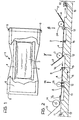
- Figure 1 illustrates schematically a disposable diaper for infants or incontinent adults, which can be manufactured by the method and apparatus according to the invention,
- Figure 2 illustrates schematically the method of the invention
- Figure 3 illustrates the basic elements of the apparatus of the invention,
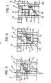
- Figure 4 is a section taken on the line IV-IV of Figure 4, and
- Figures 5 to 7 illustrate schematically the criteria which govern the operation of several of the elements illustrated in Figures 3 and 4.
- In Figure 1, a disposable absorbent diaper for infants or incontinent adults is generally indicated 1.
- The
diaper 1 is constituted essentially by asheet 2 of impermeable plastics material, for example a polyethylene film having a thickness of 25 - 30 microns. - To the
sheet 2, which is approximately rectangular, is applied anabsorbent body 3 of elongate form constituted by a wad of dry ground cellulose or like material. - Although retaining a generally elongate form, the-
absorbent body 3 may however have different shapes from that shown in Figure 1, for example an anatomical shape with end parts which are wider than the central area. - Two
elastic strip elements 4 are glued to thesheet 2 along the longer edges of theabsorbent body 3. - The longer sides of the
impermeable sheet 2 have central parts which are curved inwardly and define the so-called leg portions of the-diaper,that is, the portions of the edge which will surround a user's legs. - The
elastic elements 4 are supplied to theimpermeable sheet 2 in a state of tension; the resilient contraction force they exert causes thediaper 1 to curve into an anatomical bowl shape which helps the flow of physiological liquids to theabsorbent body 3. - The diaper is secured around the user's waist by interconnecting the shorter sides of the
impermeable sheet 2 constituting the outer covering of the diaper at their ends by means of the usual adhesive tabs, indicated 5. - The
absorbent body 3 is normally fixed to theimpermeable sheet 2 by a further fluid-permeable covering sheet, indicated 6. The coveringsheet 6, which is intended to come into contact with the user's skin, is preferably made from a nonwoven fabric so as to minimise the irritation resulting from chafing against the user's skin. - The
elastic elements 4 are fixed to theimpermeable body 2 by an adhesive strip of hot-melt material, the setting time of which is quick enough to allow theelastic elements 4 to be applied to theimpermeable sheet 2 at the high rate used in industrial production. - Figures 2 to 7 illustrate schematically apparatus for use in the formation of
elastic elements 4 in the method of manufacture of the diaper of Figure 1. - More particularly, in Figure 3,a drum, generally indicated 10, is rotated in a clockwise sense by drive means, not illustrated. The outer surface of the
drum 10, indicated 11, is illustrated schematically in a rectilinear development in Figure 2. -
First jaws 12 for clamping aweb 13 of rubber or similar elastic material to the outer surface of the drum are mounted in equiangularly distributed positions on theouter surface 11 of thedrum 10. Theweb 13 is supplied continuously to the drum from a supply source illustrated schematically as a group of motor-driven pulleys or rollers, generally indicated 14. - The velocity at which the
web 13 is supplied from thesource 14 may be controlled precisely,in the manner which will be explained in greater detail below. - The
jaws 12, of which there are four, are located at 90° to each other around the perimeter of thedrum 10 and may be of any known type, for example of the type illustrated in the U.S. Patent No. 4,297,157 mentioned above. - Four further jaws for clamping the
web 13, indicated 15, are mounted on the outer surface of thedrum 10 in alternation with thejaws 12. - With regard to the manner of operation and particularly the clamping of the
web 13, thejaws 15 are substantially similar to thejaws 12. - However, while the
jaws 12 are fixed to thedrum 10, each of the jaws 15 (Figures 4 to 7) is mounted on asupport carriage 16 which can effect a translational movement along thesurface 11 of thedrum 10 on profiled slidingguides 17 which are typically arcuate and extend tangentially relative to thedrum 10 in planes perpendicular to the axis of thedrum 10 itself. - As a result of the sliding of the
support carriages 16 along theguides 17, eachjaw 15 can effect a translational movement along thesurface 11 of thedrum 10 between two extreme positions indicated A and B respectively in Figures 2 and 3. - More particularly, in Figure 3, only one
jaw 15 is illustrated in the first position A while the other threejaws 15 are illustrated in the second position B. - In Figure 2, which, as mentioned above, shows an ideal linear development of the surface of the
drum 10, ajaw 15 in the first position A is shown on the left-hand side, twojaws 15 in the second position B are shown in the centre, and ajaw 15 which is returning to the first position A from the position B is shown on the right-hand-side. - In the first position, each jaw 15 (movable jaw) is immediately behind the jaw 12 (fixed jaw) preceding it in the direction of movement of the
surface 11 of thedrum 10. - In the rectilinear development of Figure 2, this movement is shown as developing from left to right.
- In the second position B, each
movable jaw 15 is in a position intermediate the fixedjaws 12 between which it is positioned. - The length of the
guides 17, that is,the amplitude of the movement of themovable jaws 15 between the first position A and the second position B, is selected so that, in the second position B, the distance between eachmovable jaw 15 and the fixedjaw 12 which it follows in the direction of movement of theouter surface 11 of thedrum 10 is substantially identical to the length of the tensioned elastic elements to be formed. - In the present description and in the following claims, the terms "upstream" and "downstream" are used for the relative positions of the
jaws surface 11 of thedrum 10, with reference to the direction of movement of the surface acting as a support for the formation of theelastic elements 4. More particularly, of two adjacent jaws which pass successively in front of the group ofpulleys 14 which supply theweb 13, the first jaw is termed the "upstream" jaw while the other jaw is termed the "downstream" jaw. Hence,with reference to the development of Figure 2, each jaw illustrated in this drawing is "upstream" of the jaws to its left and "downstream" of the jaws to its right. - Each
support carriage 16 has a pair of rollers orbearings 18 beneath it which cooperate with the opposite faces of a rib provided on the radially outer face of adrive carriage 19 underlying it (in a radial direction relative to the drum 10). - This rib , indicated 20 in the drawings, has a generally arcuate course which follows the curvature of the
drum 10 and extends in a plane inclined at about 45° to the planes containing theguides 17. Therib 20 constitutes a ramp part for causing the translational movement of thesupport carriage 16 along theguides 17 as a result of the translation of thedrive carriage 19 axially relative to thedrum 10. - In a structurally similar disposition to that of the
support carriages 16, each drivecarriage 19 is movable alongstraight guides 21 which extend axially relative to thedrum 10. - In the embodiment illustrated, there are eight guides 21 (two for each drive carriage 20) and these are mounted on the
drum 21 in angular positions intermediate the ends of the path of movement of thesupport carriage 16 on theguides 17. - The internal structure of the
drum 10 is illustrated in greater detail in Figure 4. In this drawing, thereference 22 indicates a horizontal-axis drive shaft on which is rigidly keyed a disc 23(or functionally equivalent element such as a ring) supporting theouter surface 11 of thedrum 10 on its free edge. This surface is normally constituted by a curved sheet-metal plate possibly treated with a non-stick material, such as a silicone rubber, for reasons which will be better explained below. - The
guides 21 extend between the disc or ring (rotor) 23 and the front surface of thedrum 10 in correspondence with which themovable jaws 15 and the fixedjaws 12 aligned therewith act. - At their ends opposite the
rotor 23, theguides 21 are connected by a stiffeningelement 24 which is also rotated by theshaft 22. - Two annular elements, indicated 25 and 26, are fitted onto the
drive shaft 22 with the interposition ofbearings shaft 22 itself. - More particularly, the
annular elements drum 10, schematically indicated H in Figure 3. These are therefore stationary relative to thedrum 10 and may act easily as support elements for theshaft 22. - The
annular elements jaws carriages 16 supporting themovable jaws 15. - In the embodiment illustrated, the operation (opening-closing) of the
jaws movable units 29, one of which is illustrated schematically in Figure 4 and each of which has afeeler roller 30 which rolls on the peripheral edge of theannular element 21 against which it is urged by aspring 31. - More particularly, when the
roller 30 is thrust outwardly of thedrum 10, the correspondingjaw movable jaw 15. In its open position, eachjaw web 13 supplied from thesupply station 14 or, as will be better seen below, allow the removal of a web piece constituting one of the tensioned elastic elements to be formed from the surface of thedrum 10. When the feeler roller is returned to thedrum 10 under the action of thespring 31, the correspondingjaw web 13 onto the surface of thedrum 10. - As schematically illustrated in Figure 3, the peripheral edge of the
annular element 25 comprises two consecutive semicircular portions concentric with thedrum 10. One of these portions, indicated 25a, has a larger radius and extends in correspondence with the lower half of the circular path of movement of the outer surface of thedrum 11 between two angular positions schematically indicated o( and β in Figure 3. - The other edge portion of the
element 25, indicated 25b,extends between the angular positions 0( and β in correspondence with the upper half of the circular path of movement of the surface of thedrum 10. Thus, the arrangement is such that, during the rotation of thedrum 10, thejaws surface 11 are in a clamped or closed position, while thejaws - For an easier understanding of the invention, references indicative of the developed relative locations of the angular positions α and β are given in Figure 2.
- From the peripheral edge of the
annular element 26 projects a profiled rib the opposite sides of which constitute rolling surfaces for a pair ofbearings 33 mounted on the radially inner face of eachdrive carriage 19 in a disposition substantially similar to that adopted by thebearings 18 of thesupport carriage 16. - As is partially visible in Figure 4, the
rib 32, which extend in continuity with the outer edges of theannular element 26, includes portions disposed in different orthogonal planes to thedrive shaft 22 and inclined portions which connect these portions orthogonal to theshaft 22. - The
rib 32 thus constitutes a cam which controls the axial translational movement of thedrive carriages 19 along theguides 21,and consequently the translational movement of thecarriages 16 supporting the movable jaws l5,between the positions A and B defined above. - The action fulfilled by the
rib 32 is illustrated schematically in Figures 5 to 7. - In the position illustrated in Figure 5, which relates to a possible relative disposition assumed by a
support carriage 16 and itsdrive carriage 19 in a portion of the path of rotation of thesurface 11 of thedrum 10, therollers 33 of thedrive carriage 19 engage aportion 32a of therib 32,which lies in a plane normal to the axis of rotation of thedrum 10. The axial position of this plane relative to the drum is such that thedrive carriage 19 is in the position of maximum advancement towards the front surface of the drum itself,and thecorresponding support carriage 17 is in a position which, purely by way of example, has been made to correspond with the location of thejaw 15 supported by the carriage in the first position A. - Figure 6 illustrates a situation in which, as a result of the rotation of the
drum 10, the rollers: 33,which are only partially visible in the drawing since they are shown in broken outline engage an inclined portion 32b of therib 32, that is, a portion of therib 32 which is moving gradually away from the frontal face of thedrum 10. Under these conditions, thedrive carriage 19 also moves away from the front surface, while therollers 18 of thesupport carriage 16 slide along therib 20 , gradually drawing thesupport carriage 16 towards the other end position of its translational movement along theguides 17. - Finally ,Figure 7 illustrates a situation in which, as a result of the further rotation of the
drum 10, therollers 33 slidingly engage a further portion of therib 32, 'indicated 32c, which lies in a plane normal to the axis of rotation of the drum. In this case, the axial position of this plane relative to thedrum 10 is such that thedrive carriage 19 driven by therollers 33 is in the position of maximum withdrawal relative to the frontal face of thedrum 10. - Under these conditions, the
rollers 18 have completed their course of sliding movement along therib 20, carrying thesupport carriage 10 and themovable jaw 15 mounted thereon into the travel limit position indicated B. - From what has been described in outline with reference to Figures 5 to 7,one may easily understand how the
rib 32 may be profiled so as to obtain any law of movement of thecarriages 16 along thesurface 11 of thedrum 10. - In Figure 3, α and δ indicate two further angular positions of the path of rotation of the surface of the
drum 10. These angular positions are diametrally opposed in a direction perpendicular to the direction of alignment of the angular positions α and β previously defined. - Figure 2 shows approximately the location of the angular position α in the rectilinear development of the surface of the
drum 10. - In the embodiment illustrated, the
rib 32 provided on the peripheral edge of thetubular element 26 has a profile such that all thesupport carriages 16 and theirmovable jaws 15 are in the first position A in correspondence with the angular position α, and move gradually towards the second position B during the advance from the angular position α to the angular position o caused by the rotation of thedrum 10. - In the portion of the path of movement of the surface of the
drum 10 between the angular positions α and β, thesupport carriages 16 and theirmovable jaws 15 are held in the second position B. - Two rollers, indicated 34, are located in positions substantially tangential to the
roller 20 in correspondence with this path portion. A continuous sheet of impermeable plastics material indicated 2 by analogy with Figure l,unwinds between therollers 34. - The
sheet portion 2 between therollers 34 adheres to theouter surface 11 of thedrum 10 and is drawn thereby as a result of the rotation of the drum itself. - Before its supply to the
drum 10, an adhesive, for example a hot-melt adhesive,is applied to thesheet 2 so as to form a firm connection between thesheet 2 and theelastic web pieces 13 which are brought into contact therewith in the manner which will be described more fully below. - The application of the hot-melt adhesive to the sheet is carried out at a spreading station,not shown in the drawings. As a possible alternative, the hot-melt adhesive may be applied to the
elastic web 13 by a spreading device which acts on theelastic web 13 adjacent to the angular position - This spreading device is illustrated schematically in broken outline and indicated S in Figure 3.
- Since, as illustrated in Figure 1, each
diaper 1 has twoelastic elements 4 disposed parallel to each other on opposite sides of theabsorbent body 3, in its application to the manufacture of these products the apparatus according to the invention includes two structures for forming elastic elements which are identical to each other and operate in parallel. For example, it is possible to provide a configuration of fixedjaws 12 and movable jaws 15 (with their drive means and the feed for the web) similar to that described above on both frontal faces of therotary drum 10. - For obvious reasons of simplicity in the present description , only the members which effect the application of one of the
elastic elements 4 are shown, since the application of the other elastic element is achieved in exactly the same way. - Downstream of the angular position β in the direction of movement of the surface of the
drum 10, thesupport carriages 16 and themovable jaws 15 mounted thereon are carried gradually towards the first position A. - In the embodiment illustrated, the
rib 32, acting as an operating cam for thecarriages carriages 16 and thejaws 15 remain in the position B until the angular position d is reached, and then turn to the first position A during the advance along the arc of the path of movement of the surface of the drum between the angular position or and the angular position α , returning to the initial conditions described above. - It should be stressed that the relative disposition of the angular positions indicated α, β, α and δ illustrated in Figure 3 (a uniform angular distribution with a spacing of 90°) is purely by way of example as a proposed solution which is of particular advantage when four fixed
jaws 12 and fourmovable jaws 15 project from the surface of thedrum 10. Depending on the application or requirements, a different disposition may of course be used, particularly when there is a different number of fixed and movable jaws on the outer surface of thedrum 10. - Finally, a cutting
element 35,for example a rotary blade, is shown which acts on theelastic web 13 applied to the surface of thedrum 10 in correspondence with the angular position α. More specifically, the cuttingelement 35 can act on theweb portion 13 between eachfixed jaw 12 and themovable jaw 15 downstream of this fixedjaw 12, when the two jaws pass through the angular position 0( as a result of the rotation of thedrum 10. As indicated above, under these conditions,themovable jaw 15 is in the first position A. - The cutting
member 35 is intended to section thecontinuous web 13, cutting tensioned web pieces constituting theelastic elements 4 to be applied to theplastics sheet 2 from the continuous body of theweb 13. - The operation of the apparatus according to the invention is effected by rotating of the
drum 10 and operating of the supply source for the web 13 (shown schematically as the rollers 14) and the cuttingmember 35 simultaneously and continuously. As a result of the presence of theannular elements drum 10 drives the closing and opening of thejaws jaws 15 between the first position A and the second position B, as explained above. - The values chosen for the translational velocity of the
movable jaws 15 and the supply velocity of theelastic web 13 from the source l4,in dependence on the velocity of rotation of thedrum 10,are of paramount importance for the carrying out of the invention. - By way of example, it is assumed that the
drum 10 has a rotational velocity ω1 such that theouter surface 11 of thedrum 10 moves in a clockwise sense with a tangential velocity V 1. - The portion of the
rib 32 between the angular positions α and β, which acts as a drive cam for thecarriages 16 on which thejaws 15 are mounted, has a profile such that the translational movement of thejaws 15 between the position A and the positionB is effected at a velocity V2 (relative to thesurface 11 of the drum 10) which is less than the velocity V1 of advance imparted to the surface itself as a result of the rotation of thedrum 10. - The translational velocity of the
jaws 15 from the first position A to the second position B is in the opposite direction from that of the velocity V1, as shown schematically by the respective arrows in Figure 2. - The superposition of the rotational movement of the
drum 10 on the movement of thejaws 15 from the first position A to the second position B means that, while thesurface 11 of thedrum 10 travels with a tangential velocity V1 through the arc between the angular position α and the angular position α, thejaws 15 mounted thereon have a tangential velocity equal to V1 - V2 and thus travel only through a part of this arc. - More particularly, the value of the velocity V2 is chosen so that (see Figure 3) each
movable jaw 15 reaches the second position B having left the first position A exactly when the fixedjaw 12 located downstream in the direction of advance of the surface of the drum reaches the angular position in which the cuttingmember 35 acts. - With reference to the embodiment illustrated, the second position B of the
movable jaws 15 is chosen so that, in this second position, eachmovable jaw 15 is in a median position relative to the fixedjaws 12 between which it is positioned. The profile of therib 32 is thus selected so that the value of the velocity V2 is equal to half the value of the tangential velocity V1 of the surface of thedrum 10. - Thus, it is possible, while the surface of the
drum 10 advances through an arc of 90° between the angular positions 0< and α, to make themovable jaw 15 mounted thereon advance through an arc of only 45°, that is, an arc equal to half the arc travelled by the surface of thedrum 10. - Naturally, after reaching the second position B halfway between the angular positions α and α, each
movable jaw 15 stops moving translationally relative to thedrum 10 and is drawn thereby at the velocity V 1. - With regard to the supply velocity of the
web 13 from thesource 14, the velocity indicated V3, this is chosen so as to be less than the difference between the tangential velocity V1 of thesurface 11 of thedrum 10 and the translational velocity V2 of thejaws 15 from the first position A to the position B. This difference (V1 - V2) determines the velocity at which eachmovable jaw 12 passes through the initial portion of the arc between the angular positiondand the angular position intermediate the positions α and α at which thejaw 15 itself reaches the second position B. With reference to the choice of values indicated above, V2 is equal to half V1 whereby this difference is also equal to half V1. - The fact that a value of the web supply velocity is chosen to be less than the velocity difference means that the
web 13 is applied to the surface of thedrum 10 under tension. - The degree of this tension is determined by the ratio between the velocity difference V1 - V2 = 2 V1 and the web supply velocity V3. More particularly, in the currently preferred embodiment, by selecting a supply velocity value V3 for the web which is equal to 1 4 V1, it is possible for the
web 13 to be applied to the surface of thedrum 10 in a state of tension equal to 100%, that is,a state in which a unitary element of the tensioned web has a length equal to twice its rest length. - The sequence of operations of the apparatus according to the invention will now be explained with specific reference to Figure 2. This drawing may be interpreted as a linear development of the disposition assumed at a predetermined instant by the
jaws drum 10, and as an illustration of a chronological sequence of the positions reached successively by a single fixed jaw-movable jaw unit. At its left- hand side, Figure 2 illustrates the relative positions assumed by amovable jaw 15 and the fixedjaw 12 located downstream thereof in the direction of advance of thesurface 11 of the drum when theweb 13 is clamped in themovable jaw 15 which is located in the first position A in correspondence with the position α. - The
web piece 13 which is clamped in themovable jaw 15 corresponds,in fact,to the free end of theweb 13 itself in that, immediately upstream of thejaw 15, the cuttingmember 35 cuts theweb 13 to separate a piece of web formed previously in the manner which will now be described. - Immediately the
surface 11 of the drum passes through the angular position α at a tangential velocity Vl, themovable jaw 15 starts to move on thesurface 11 towards the second position B at a velocity V2 the value of which, as indicated above, is equal to half the value of the tangential velocity V1. - Under these conditions, the end of the
web 13 clamped in thejaw 15 advances relative to thesource 14, which is stationary, at a velocity equal to the difference V1 - V2, that is, at a velocity equal to half V1. - The
web 13 is supplied at a velocity equal to a quarter of V1, that is, at a velocity less than the difference V1 - V2. Theweb portion 13 between themovable jaw 15 and thesource 14 is thus stretched longitudinally, which puts it under tension. With the velocity values indicated above (V1 - V2 = 2V3) theweb 13 is stretched by 100% and, being under tension, has a length equal to twice the relaxed length. As illustrated schematically in the central part of Figure 2, themovable jaw 15 reaches the position B at half the arc of the path between the angular positions α and γ exactly when the fixedjaw 12 located downstream. thereof reaches the angular position α together with a furthermovable jaw 15 which has just returned to the first position A. Under the action of thecam 25,the fixedjaw 12 and the furthermovable jaw 15 close on the web supplied by thesource 14. Between the fixedjaw 12 and themovable jaws 15 located upstream in positions intermediate the positions α and there is thus formed a tensioned web piece which can be applied to thesheet 2. This piece is separated from the main body of theweb 13 by the cuttingmember 35 which actson the web portion between the fixedjaw 12 and the further movable jaw located immediately downstream. - The cutting
member 35 thus forms a new free end of theweb 13 destined to be drawn at the velocity V1 - V2 by the further movable jaw during the cycle of formation of a new tensioned elastic piece. - The tensioned elastic piece which has just been formed, of which the ends are clamped between the
movable jaw 15 and the fixedjaw 12, advances towards the angular position at a tangential velocity V1. - In the manner briefly described above, in the arc between the angular positions α and β, the piece is stuck to the
plastics sheets 2 as anelastic element 4 which can confer elasticity and greater adherence to the diaper. - When the adhesive has set (typically around the angular position indicated Z ),the
jaws plastics sheet 2 is removed from thesurface 11 of thedrum 10, drawing with it theelastic elements 4 applied thereto. - As indicated above, at least those portions of the
surface 11 of thedrum 10 for conveying theweb pieces 13 are preferably coated with a resilient material, such as a silicone rubber, in order to facilitate the detachment of thesheet 2 carrying the appliedelastic elements 4 from thedrum 10 itself. - In the end part of the path of movement of the
surface 11, between the angular position δ and α, themovable jaw 15 returns to the first position A to receive theweb 13 again and to start a new cycle of formation of anelastic element 4. - In the embodiment illustrated in Figure 3, four equiangularly spaced-apart fixed jaw-movable jaw units are provided on the surface of the drum. In the development of the surface of the
drum 10 between the angular position α and the angular position2f, it is thus possible to see a unit in which a tensioned elastic piece has just been formed. The rear end (in the direction of translational movement of the surface of the drum) of the piece is separated from the main body of theweb 13 by the cuttingmember 35. - Between the angular positions α and β however, there can be seen the other unit which pulls a tensioned elastic piece causing it to stick to the
plastics sheet 2 unwinding from therollers 34. - Between the angular positions β and δ ,there can be seen a unit in which the fixed
jaw 12 is open, as is themovable jaw 15 preceding it, to allow anelastic piece 4 firmly applied to thesheet 2 to move away from the drum. - Finally, between the angular positions δ and α, there can be seen a unit in which the
movable jaw 15 has returned to the first position A to receive the new free end of theweb 13. This new free end is formed by theelement 35 during the cutting operation which separates the tensioned the elastic piece just formed in the unit located between the angular positions α and a from the main body of theweb 13. - A method and apparatus are thus described which allow the rapid formation of tensioned elastic elements, in a manner which can be achieved practically and economically on an industrial scale, it being possible to stick these tensioned elastic elements to a support such as a sheet of impermeable plastics material forming the outer covering of a sanitary product such as a disposable diaper.
- More particularly, it may be seen that the invention allows the formation of tensioned elastic elements while avoiding the disadvantages typical of the prior art.
- More particularly, the elastic elements formed according to the invention can be stuck to an inelastic support avoiding the wastage of material resulting from the formation of tails which will return to the rest condition after application.
- Furthermore, in no stage of the method for the formation of the elastic elements is the material of the web subjected to tensions greater than that needed for application to the final product. Thus, the typical disadvantages resulting from over-stretching of the elastic web during working are avoided.
- Naturally, the principle of the invention remaining the same, the constructional details and forms of embodiments may be varied widely with respect to that described and illustrated,without thereby departing from the scope of the present invention.
Claims (11)
Priority Applications (1)
| Application Number | Priority Date | Filing Date | Title |
|---|---|---|---|
| AT84830272T ATE35608T1 (en) | 1983-10-12 | 1984-10-11 | METHOD AND DEVICE FOR FORMING STRETCHED ELASTIC ELEMENTS FROM A CONTINUOUS ELASTIC TAPE, ESPECIALLY FOR THE MANUFACTURE OF HYGIENE ARTICLES SUCH AS DISPOSABLE NAPPIES OR THE LIKE. |
Applications Claiming Priority (2)
| Application Number | Priority Date | Filing Date | Title |
|---|---|---|---|
| IT68052/83A IT1161511B (en) | 1983-10-12 | 1983-10-12 | PROCESS AND EQUIPMENT FOR THE FORMATION OF ELASTIC ELEMENTS IN VOLTAGE STARTING FROM A CONTINUOUS ELASTIC TAPE, PARTICULARLY FOR THE MANUFACTURE OF SANITARY PRODUCTS SUCH AS SINGLE USE AND SIMILAR PANELS |
| IT6805283 | 1983-10-12 |
Publications (3)
| Publication Number | Publication Date |
|---|---|
| EP0139620A2 true EP0139620A2 (en) | 1985-05-02 |
| EP0139620A3 EP0139620A3 (en) | 1986-09-03 |
| EP0139620B1 EP0139620B1 (en) | 1988-07-13 |
Family
ID=11307489
Family Applications (1)
| Application Number | Title | Priority Date | Filing Date |
|---|---|---|---|
| EP84830272A Expired EP0139620B1 (en) | 1983-10-12 | 1984-10-11 | Method and apparatus for forming elastic elements under tension from a continuous elastic web, particularly for manufacturing sanitary products such as disposable diapers and the like |
Country Status (6)
| Country | Link |
|---|---|
| US (1) | US4572043A (en) |
| EP (1) | EP0139620B1 (en) |
| AT (1) | ATE35608T1 (en) |
| DE (1) | DE3472618D1 (en) |
| ES (1) | ES536971A0 (en) |
| IT (1) | IT1161511B (en) |
Cited By (9)
| Publication number | Priority date | Publication date | Assignee | Title |
|---|---|---|---|---|
| EP0183668A2 (en) * | 1984-11-30 | 1986-06-04 | Mölnlycke AB | Absorption article such as a diaper or a sanitary napkin, and a method for the manufacture thereof |
| FR2594651A1 (en) * | 1986-02-21 | 1987-08-28 | Colgate Palmolive Co | MACHINE FOR FASTENING ON A CONTINUOUSLY FLOORING PATCH OF THE ELASTIC BAND TENSIONED STRINGS AND INSTALLATION FOR THE PRODUCTION OF CULOT LAYERS COMPRISING THE APPLICATION |
| EP0304044A1 (en) * | 1987-08-18 | 1989-02-22 | Uni-Charm Corporation | Apparatus for applying elastic band onto moving web |
| EP0338662A2 (en) * | 1988-04-19 | 1989-10-25 | Paper Converting Machine Company | Method and apparatus for applying an elastic waistband to a disposable diaper |
| US5000806A (en) * | 1988-04-19 | 1991-03-19 | Paper Converting Machine Company | Method and apparatus for applying an elastic strand to a disposable diaper |
| EP0464865A2 (en) * | 1985-10-28 | 1992-01-08 | Kimberly-Clark Corporation | Method and apparatus for applying contoured elastic to a substrate |
| GB2260906A (en) * | 1991-10-31 | 1993-05-05 | Ardfert Ltd | Process for the manufacture of disposable nappies |
| WO1995011650A1 (en) * | 1993-10-25 | 1995-05-04 | The Procter & Gamble Company | Method and apparatus for combining a tensioned elastic member with a moving substrate web |
| US5660665A (en) * | 1995-12-15 | 1997-08-26 | Kimberly-Clark Corporation | Rotating transfer roll with rotating extensible platen |
Families Citing this family (8)
| Publication number | Priority date | Publication date | Assignee | Title |
|---|---|---|---|---|
| DE3444331A1 (en) * | 1984-12-05 | 1986-06-05 | Winkler & Dünnebier, Maschinenfabrik und Eisengießerei GmbH & Co KG, 5450 Neuwied | METHOD AND DEVICE FOR APPLYING ELASTIC TAPES ON A MATERIAL RAIL |
| DE3637110C1 (en) * | 1986-10-31 | 1988-05-19 | Heidelberger Druckmasch Ag | Device for cutting and dividing a continuous flow of printed products |
| US5716478A (en) * | 1995-10-17 | 1998-02-10 | Kimberly-Clark Worldwide, Inc. | Apparatus and method for applying discrete parts onto a moving web |
| US6165306A (en) | 1998-06-01 | 2000-12-26 | Kimberly-Clark Worldwide, Inc. | Process and apparatus for cutting of discrete components of a multi-component workpiece and depositing them with registration on a moving web of material |
| US6074333A (en) * | 1998-12-24 | 2000-06-13 | Kimberly-Clark Worldwide, Inc. | Machine for cutting discrete components of a multi-component workpiece and depositing them with registration on a moving web of material |
| US6059710A (en) * | 1998-12-24 | 2000-05-09 | Kimberly-Clark Worldwide, Inc. | Process for cutting of discrete components of a multi-component workpiece and depositing them with registration on a moving web of material |
| CN101173490B (en) * | 2007-11-01 | 2010-04-14 | 安庆市恒昌机械制造有限责任公司 | Full peripheral high air permeability wood pulp cellulose solid shaping wheel hub |
| US7901534B2 (en) * | 2008-09-25 | 2011-03-08 | Attends Healthcare Products, Inc. | Method of making diapers with substantially reduced production of discarded waste material |
Citations (4)
| Publication number | Priority date | Publication date | Assignee | Title |
|---|---|---|---|---|
| DE2630878A1 (en) * | 1975-07-11 | 1977-01-20 | Procter & Gamble | METHOD AND DEVICE FOR FOLDING AND SEPARATING DISPOSABLE DIAPERS OR THE SAME WITH STRETCHED ELASTIC TAPE ATTACHED TO A WEB |
| US4081301A (en) * | 1975-10-30 | 1978-03-28 | The Procter & Gamble Company | Method and apparatus for continuously attaching discrete, stretched elastic strands to predetermined isolated portions of disposable abosrbent products |
| US4297157A (en) * | 1980-06-23 | 1981-10-27 | Weyerhaeuser Company | Method for application of elastic to articles |
| DE3136643A1 (en) * | 1981-09-16 | 1983-04-21 | Albert 2800 Bremen Stichhan | Process and devices for applying individual elastic tapes to travelling webs |
Family Cites Families (4)
| Publication number | Priority date | Publication date | Assignee | Title |
|---|---|---|---|---|
| CA1146129A (en) * | 1980-08-22 | 1983-05-10 | Edmund Radzins | Apparatus for applying elastic ribbon segments to diapers |
| US4397704A (en) * | 1980-10-20 | 1983-08-09 | Kimberly-Clark Corporation | Method and apparatus for applying discrete lengths of elastic strip material to a continuously moving web |
| JPS59112010A (en) * | 1982-12-15 | 1984-06-28 | ユニ・チャ−ム株式会社 | Disposable sanitary article and attachment of elastic memberthereto |
| US4523969A (en) * | 1984-01-09 | 1985-06-18 | Paper Converting Machine Company | Method and apparatus for manufacturing a product having elastic means disposed in a direction transverse to product movement |
-
1983
- 1983-10-12 IT IT68052/83A patent/IT1161511B/en active
-
1984
- 1984-10-11 EP EP84830272A patent/EP0139620B1/en not_active Expired
- 1984-10-11 ES ES536971A patent/ES536971A0/en active Granted
- 1984-10-11 DE DE8484830272T patent/DE3472618D1/en not_active Expired
- 1984-10-11 AT AT84830272T patent/ATE35608T1/en not_active IP Right Cessation
- 1984-10-12 US US06/660,193 patent/US4572043A/en not_active Expired - Lifetime
Patent Citations (4)
| Publication number | Priority date | Publication date | Assignee | Title |
|---|---|---|---|---|
| DE2630878A1 (en) * | 1975-07-11 | 1977-01-20 | Procter & Gamble | METHOD AND DEVICE FOR FOLDING AND SEPARATING DISPOSABLE DIAPERS OR THE SAME WITH STRETCHED ELASTIC TAPE ATTACHED TO A WEB |
| US4081301A (en) * | 1975-10-30 | 1978-03-28 | The Procter & Gamble Company | Method and apparatus for continuously attaching discrete, stretched elastic strands to predetermined isolated portions of disposable abosrbent products |
| US4297157A (en) * | 1980-06-23 | 1981-10-27 | Weyerhaeuser Company | Method for application of elastic to articles |
| DE3136643A1 (en) * | 1981-09-16 | 1983-04-21 | Albert 2800 Bremen Stichhan | Process and devices for applying individual elastic tapes to travelling webs |
Cited By (16)
| Publication number | Priority date | Publication date | Assignee | Title |
|---|---|---|---|---|
| EP0183668A2 (en) * | 1984-11-30 | 1986-06-04 | Mölnlycke AB | Absorption article such as a diaper or a sanitary napkin, and a method for the manufacture thereof |
| EP0183668A3 (en) * | 1984-11-30 | 1987-09-16 | Molnlycke Ab | Absorption article such as a diaper or a sanitary napkin, and a method for the manufacture thereof |
| EP0464865A3 (en) * | 1985-10-28 | 1992-08-26 | Kimberly-Clark Corporation | Method and apparatus for applying contoured elastic to a substrate |
| EP0464865A2 (en) * | 1985-10-28 | 1992-01-08 | Kimberly-Clark Corporation | Method and apparatus for applying contoured elastic to a substrate |
| FR2594651A1 (en) * | 1986-02-21 | 1987-08-28 | Colgate Palmolive Co | MACHINE FOR FASTENING ON A CONTINUOUSLY FLOORING PATCH OF THE ELASTIC BAND TENSIONED STRINGS AND INSTALLATION FOR THE PRODUCTION OF CULOT LAYERS COMPRISING THE APPLICATION |
| EP0236032A2 (en) * | 1986-02-21 | 1987-09-09 | PTM, Inc. | Machine for fastening stretched pieces of elastic band to a continuously moving sheet and apparatus for the production of diapers involving its use |
| EP0236032A3 (en) * | 1986-02-21 | 1988-11-30 | Colgate-Palmolive Company | Machine for fastening stretched pieces of elastic band to a continuously moving sheet and apparatus for the production of diapers involving its use |
| EP0304044A1 (en) * | 1987-08-18 | 1989-02-22 | Uni-Charm Corporation | Apparatus for applying elastic band onto moving web |
| US5000806A (en) * | 1988-04-19 | 1991-03-19 | Paper Converting Machine Company | Method and apparatus for applying an elastic strand to a disposable diaper |
| EP0338662A3 (en) * | 1988-04-19 | 1990-04-04 | Paper Converting Machine Company | Method and apparatus for applying an elastic waistband to a disposable diaper |
| EP0338662A2 (en) * | 1988-04-19 | 1989-10-25 | Paper Converting Machine Company | Method and apparatus for applying an elastic waistband to a disposable diaper |
| US5296080A (en) * | 1988-04-19 | 1994-03-22 | Paper Converting Machine Company | Apparatus for applying an elastic waistband to a disposable diaper |
| GB2260906A (en) * | 1991-10-31 | 1993-05-05 | Ardfert Ltd | Process for the manufacture of disposable nappies |
| GB2260906B (en) * | 1991-10-31 | 1995-11-15 | Ardfert Ltd | Disposable nappy manufacturing process |
| WO1995011650A1 (en) * | 1993-10-25 | 1995-05-04 | The Procter & Gamble Company | Method and apparatus for combining a tensioned elastic member with a moving substrate web |
| US5660665A (en) * | 1995-12-15 | 1997-08-26 | Kimberly-Clark Corporation | Rotating transfer roll with rotating extensible platen |
Also Published As
| Publication number | Publication date |
|---|---|
| DE3472618D1 (en) | 1988-08-18 |
| US4572043A (en) | 1986-02-25 |
| ATE35608T1 (en) | 1988-07-15 |
| ES8600612A1 (en) | 1985-10-16 |
| IT1161511B (en) | 1987-03-18 |
| EP0139620B1 (en) | 1988-07-13 |
| EP0139620A3 (en) | 1986-09-03 |
| IT8368052A0 (en) | 1983-10-12 |
| ES536971A0 (en) | 1985-10-16 |
Similar Documents
| Publication | Publication Date | Title |
|---|---|---|
| EP0139620B1 (en) | Method and apparatus for forming elastic elements under tension from a continuous elastic web, particularly for manufacturing sanitary products such as disposable diapers and the like | |
| US4525229A (en) | Method for attaching elastic band to sanitary articles | |
| EP0047106B1 (en) | Method of and apparatus for fixing elastic ribbon between interfacing nominally inelastic flexible sheets | |
| EP0209207B1 (en) | Method and apparatus for securing elastic strands to disposable absorbent articles | |
| US4081301A (en) | Method and apparatus for continuously attaching discrete, stretched elastic strands to predetermined isolated portions of disposable abosrbent products | |
| US4801345A (en) | Process for manufacturing disposable diapers and diaper briefs, and disposable diapers and diaper briefs obtained by application of this process | |
| US5000806A (en) | Method and apparatus for applying an elastic strand to a disposable diaper | |
| US4479836A (en) | Method for effecting securement of alternating stretched and unstretched elastic ribbon to a moving web | |
| US4666542A (en) | Process for the production of disposable diaper panties | |
| US5296080A (en) | Apparatus for applying an elastic waistband to a disposable diaper | |
| US4293367A (en) | Apparatus for effecting securement of a transversely moved elastic ribbon to a moving web | |
| US4409049A (en) | Method and apparatus for effecting intermittent securement of a stretched elastic member to a moving web | |
| US4360398A (en) | Method for applying elastic bands to webs | |
| EP0409876B1 (en) | Apparatus for laying elastic thread on a web of material | |
| EP2260813B1 (en) | A device and method for forming tensioned elastication strips, for instance for sanitary articles and corresponding computer program product | |
| US4412881A (en) | Method and apparatus for manufacturing elastic leg disposable diapers | |
| JPH0333201A (en) | Production of disposable brief | |
| KR20100024428A (en) | A machine and a method for manufacturing absorbent articles | |
| CA2547464A1 (en) | High speed vacuum porting | |
| GB2113983A (en) | Apparatus and method for applying elastic strip material to a moving web | |
| US4432823A (en) | Method and apparatus for manufacturing elastic leg disposable diapers | |
| US4488923A (en) | Method for producing a fabric having unsecured elastic in areas intermittently disposed along an edge thereof | |
| US3557156A (en) | Sectional drive apparatus for continuously feeding an elastic material | |
| JPS648082B2 (en) | ||
| CA1211745A (en) | Method and apparatus for forming tensioned elastic elements |
Legal Events
| Date | Code | Title | Description |
|---|---|---|---|
| PUAI | Public reference made under article 153(3) epc to a published international application that has entered the european phase |
Free format text: ORIGINAL CODE: 0009012 |
|
| AK | Designated contracting states |
Designated state(s): AT BE CH DE FR GB LI LU NL SE |
|
| PUAL | Search report despatched |
Free format text: ORIGINAL CODE: 0009013 |
|
| AK | Designated contracting states |
Kind code of ref document: A3 Designated state(s): AT BE CH DE FR GB LI LU NL SE |
|
| 17P | Request for examination filed |
Effective date: 19870221 |
|
| 17Q | First examination report despatched |
Effective date: 19870915 |
|
| GRAA | (expected) grant |
Free format text: ORIGINAL CODE: 0009210 |
|
| AK | Designated contracting states |
Kind code of ref document: B1 Designated state(s): AT BE CH DE FR GB LI LU NL SE |
|
| PG25 | Lapsed in a contracting state [announced via postgrant information from national office to epo] |
Ref country code: SE Effective date: 19880713 Ref country code: NL Effective date: 19880713 Ref country code: AT Effective date: 19880713 |
|
| REF | Corresponds to: |
Ref document number: 35608 Country of ref document: AT Date of ref document: 19880715 Kind code of ref document: T |
|
| REF | Corresponds to: |
Ref document number: 3472618 Country of ref document: DE Date of ref document: 19880818 |
|
| ET | Fr: translation filed | ||
| PG25 | Lapsed in a contracting state [announced via postgrant information from national office to epo] |
Ref country code: LU Free format text: LAPSE BECAUSE OF NON-PAYMENT OF DUE FEES Effective date: 19881031 |
|
| NLV1 | Nl: lapsed or annulled due to failure to fulfill the requirements of art. 29p and 29m of the patents act | ||
| PLBE | No opposition filed within time limit |
Free format text: ORIGINAL CODE: 0009261 |
|
| STAA | Information on the status of an ep patent application or granted ep patent |
Free format text: STATUS: NO OPPOSITION FILED WITHIN TIME LIMIT |
|
| RAP4 | Party data changed (patent owner data changed or rights of a patent transferred) |
Owner name: FAMECCANICA S.P.A. |
|
| 26N | No opposition filed | ||
| PGFP | Annual fee paid to national office [announced via postgrant information from national office to epo] |
Ref country code: CH Payment date: 19960919 Year of fee payment: 13 Ref country code: BE Payment date: 19960919 Year of fee payment: 13 |
|
| PGFP | Annual fee paid to national office [announced via postgrant information from national office to epo] |
Ref country code: DE Payment date: 19960923 Year of fee payment: 13 |
|
| PGFP | Annual fee paid to national office [announced via postgrant information from national office to epo] |
Ref country code: FR Payment date: 19961030 Year of fee payment: 13 |
|
| PG25 | Lapsed in a contracting state [announced via postgrant information from national office to epo] |
Ref country code: LI Free format text: LAPSE BECAUSE OF NON-PAYMENT OF DUE FEES Effective date: 19971031 Ref country code: FR Free format text: THE PATENT HAS BEEN ANNULLED BY A DECISION OF A NATIONAL AUTHORITY Effective date: 19971031 Ref country code: CH Free format text: LAPSE BECAUSE OF NON-PAYMENT OF DUE FEES Effective date: 19971031 Ref country code: BE Free format text: LAPSE BECAUSE OF NON-PAYMENT OF DUE FEES Effective date: 19971031 |
|
| REG | Reference to a national code |
Ref country code: GB Ref legal event code: 732E |
|
| BERE | Be: lapsed |
Owner name: FAMECCANICA S.P.A. Effective date: 19971031 |
|
| REG | Reference to a national code |
Ref country code: CH Ref legal event code: PL |
|
| PG25 | Lapsed in a contracting state [announced via postgrant information from national office to epo] |
Ref country code: DE Free format text: LAPSE BECAUSE OF NON-PAYMENT OF DUE FEES Effective date: 19980701 |
|
| REG | Reference to a national code |
Ref country code: FR Ref legal event code: ST |
|
| PGFP | Annual fee paid to national office [announced via postgrant information from national office to epo] |
Ref country code: GB Payment date: 20010914 Year of fee payment: 18 |
|
| REG | Reference to a national code |
Ref country code: GB Ref legal event code: IF02 |
|
| PG25 | Lapsed in a contracting state [announced via postgrant information from national office to epo] |
Ref country code: GB Free format text: LAPSE BECAUSE OF NON-PAYMENT OF DUE FEES Effective date: 20021011 |
|
| GBPC | Gb: european patent ceased through non-payment of renewal fee |
Effective date: 20021011 |