EP0136769A2 - Metal-gas cell with electrolyte reservoir - Google Patents
Metal-gas cell with electrolyte reservoir Download PDFInfo
- Publication number
- EP0136769A2 EP0136769A2 EP84302828A EP84302828A EP0136769A2 EP 0136769 A2 EP0136769 A2 EP 0136769A2 EP 84302828 A EP84302828 A EP 84302828A EP 84302828 A EP84302828 A EP 84302828A EP 0136769 A2 EP0136769 A2 EP 0136769A2
- Authority
- EP
- European Patent Office
- Prior art keywords
- electrolyte
- plate
- plate stack
- stack
- bladder
- Prior art date
- Legal status (The legal status is an assumption and is not a legal conclusion. Google has not performed a legal analysis and makes no representation as to the accuracy of the status listed.)
- Withdrawn
Links
Images

Classifications
-
- H—ELECTRICITY
- H01—ELECTRIC ELEMENTS
- H01M—PROCESSES OR MEANS, e.g. BATTERIES, FOR THE DIRECT CONVERSION OF CHEMICAL ENERGY INTO ELECTRICAL ENERGY
- H01M10/00—Secondary cells; Manufacture thereof
- H01M10/34—Gastight accumulators
- H01M10/345—Gastight metal hydride accumulators
-
- H—ELECTRICITY
- H01—ELECTRIC ELEMENTS
- H01M—PROCESSES OR MEANS, e.g. BATTERIES, FOR THE DIRECT CONVERSION OF CHEMICAL ENERGY INTO ELECTRICAL ENERGY
- H01M50/00—Constructional details or processes of manufacture of the non-active parts of electrochemical cells other than fuel cells, e.g. hybrid cells
- H01M50/70—Arrangements for stirring or circulating the electrolyte
-
- Y—GENERAL TAGGING OF NEW TECHNOLOGICAL DEVELOPMENTS; GENERAL TAGGING OF CROSS-SECTIONAL TECHNOLOGIES SPANNING OVER SEVERAL SECTIONS OF THE IPC; TECHNICAL SUBJECTS COVERED BY FORMER USPC CROSS-REFERENCE ART COLLECTIONS [XRACs] AND DIGESTS
- Y02—TECHNOLOGIES OR APPLICATIONS FOR MITIGATION OR ADAPTATION AGAINST CLIMATE CHANGE
- Y02E—REDUCTION OF GREENHOUSE GAS [GHG] EMISSIONS, RELATED TO ENERGY GENERATION, TRANSMISSION OR DISTRIBUTION
- Y02E60/00—Enabling technologies; Technologies with a potential or indirect contribution to GHG emissions mitigation
- Y02E60/10—Energy storage using batteries
Definitions
- the present invention relates to an electrolyte "starved" electrochemical cell particularly a metal-gas electrochemical cell.
- Metal-gas cells particularly nickel-hydrogen cells
- These cells are contained in a sealed vessel or casing which contains hydrogen gas under high pressure.
- Each cell has at least one nickel-containing positive electrode which is spaced from a catalytic negative electrode.
- Electrodes are generally in the form of plates which are stacked together to form a plate stack.
- the plate stack includes gas access plates and separators which prevent short circuiting contact between the electrodes and which are saturated with a liquid electrolyte to provide desired cell performance.
- the electrolyte is typically an alkaline medium such as an aqueous solution of alkali metal hydroxide, such as an approximately 30% potassium hydroxide solution.
- the negative catalytic electrode is a metal powder bonded within a plastic matrix.
- the metal powder is preferably one such as platinum or palladium black which will catalyze the oxidation or dissociation of hydrogen gas in an aqueous electrolyte.
- the plastic matrix is desirably tetrafluoroethylene such as "Teflon" brand material made by duPont.
- the active nickel-containing positive electrode is generally a nickel-oxy-hydroxide.
- metal-gas cells are, by preference, electrolyte starved cells. This refers to the quantity of electrolyte within the cell.
- the plate stack including the electrodes and separators, will approach saturation with electrolyte and there may be a slight excess of electrolyte added.
- the majority of the interior of the cell casing which.is not occupied by the plate stack is filled with gaseous hydrogen. This is required to provide sufficient hydrogen to react and to provide a gas-filled space to accommodate gases that are generated during the charging or discharging of the cell.
- the pressure vessel or casing generally achieves superatomspheric pressure, for example, 20-50 atmospheres.
- Hydrogen in the vessel passes through an access plate to reach a catalytic negative electrode.
- the negative electrode causes molecular hydrogen to dissociate into atomic hydrogen which in turn reacts with free hydroxyl groups in the electrolyte to form water plus free electrons.
- the water and free electrons react with the nickel-oxy-hydroxide positive electrode to form nickel-hydroxide plus free hydroxyl ions.
- the active faces of the electrodes may tend to increase in volume, or "grow". Since these cells are electrolyte starved, this causes a substantial problem.
- This growth of the active faces of the positive electrodes compresses the separators, forcing out electrolyte from the separators.
- the expanded plates are of increased porosity; and they capture the electrolyte. .
- the separators become denser and less conductive. Therefore, the plate stack is no longer electrolyte balanced and overall cell efficiency decreases. This eventually contributes to cell failure.
- Nickel-hydrogen batteries are quickly becoming the preferred electrical storage system for earth-orbiting satellites. The reasons for this are the long life of the nickel-hydrogen cell, its wide operating range and most importantly, its high energy density. Since these are used in satellites, it is extremely important that the longevity of the cell is maximized. As such, it is critical that some means is provided to compensate for the growth of the plate stack, and preventing effective depletion of electrolyte by providing additional electrolyte to the plate stack progressively as needed.
- an electrochemical cell includes a plate stack attached to or bearing against at least one electrolyte reservoir.
- the electrolyte reservoir has a compressible bladder which, as the plate stack grows, is compressed, and which thereby forces electrolyte from the bladder into the plate stack.
- the cell utilizes the force created by its electrode growth to dispense additional electrolyte to the plate stack from an electrolyte reservoir.
- a metal-gas cell hereinafter described as a nickel-hydrogen cell, includes a cell or plate stack which is a plurality of alternating negative and positive electrodes connected to negative and positive bus bars, respectively.
- the bus bars in turn are connected to terminals which extend through the cell casing which contains the pressurized operating gas within the cell.
- a nickel-hydrogen cell 10 including an external casing 11.
- the casing is preferably made from a hard metal such as Inconel 718, an alloy principally composed of 52% nickel, 19% chromium and 18.5% iron, and which is produced by the International Nickel Company.
- the casing is a two-section casing. One section 12 comprises a cylindrical center portion 12a and a domed end portion 12b. The second section of the casing is an opposing domed end portion 13. The two sections 12 and 13 are welded together at and through an Inconel weld ring 14.
- a plate stack 16 formed from a plurality of alternating negative electrodes 18 and positive electrodes 20.
- the electrodes are in turn electrically connected to negative and positive bus bars 22 and 24, respectively, which lead to negative and positive terminals 26 and 28.
- the plate stack is formed from a plurality of layers as shown in detail in Fig. 2.
- the cell stack begins with a positive end plate 30 adjacent a gas spacer 32 such as a polypropylene mesh material which in turn contacts the laminated negative electrode 18 formed from a support lamina of Teflon backing material 34 and a platinum active lamina or face 36.
- the negative electrode 18 is separated from a positive electrode 20 by an asbestos separator 38.
- Adjacent the positive electrode 20 is a second positive electrode 20a, separated from a second negative electrode 19 by another asbestos separator 38.
- This configuration is repeated throughout the cell stack providing as many negative and positive electrodes as desired.
- such a plate stack would include 14 pairs of positive electrodes and 28 individual negative electrodes.
- the plate stack ends with a negative end plate 40 (see Fig. 1); The individual layers of the plate stack are maintained in facial contact with one another between the positive and negative end plates 30 and 40, respectively.
- the bus bars provide a complete electrical path from the negative to the positive terminal of the battery, preferably through the plate stack.
- the bent portions 42 and 43 of the bus bars 22 and 24 are connected to inner ends 46 and 48 of terminals 26 and 28.
- the terminals extend through openings in the respective domed ends 13 and 12b and are sealed by sealing stucture positioned on c the inside of the domed ends.
- Each terminal has a conical portion 50 which as the terminal is drawn up by nuts 52 compresses correspondingly tapered plastic "Teflon" primary seals 55 and secondary seals 54.
- the seals 55 and 54 are captured in a surrounding Inconel sleeve 58 which is welded to the domed ends.
- the negative end plate 40 rests against weld ring 14.
- the weld ring is an annular ring including a central hub 14a and axially extending spokes 14b. Hub 14a further includes a central aperture 14c to allow the core 62 to pass through.
- the positive end plate 30 is positioned at the end of the cell stack opposite the negative end plate 40 with the core 62 extending through the plate stack 16 through the negative end plate 40 and central aperture 14c of weld ring 14.
- the core finally extends through a Belleville washer 68.
- Nut 70 screwed onto the threaded end 64 of the core 62 holds the cell stack compressed against the weld ring.
- the Belleville washer acts as a spring maintaining a compressing force on the cell stack which permits the cell stack to grow or expand during charging and discharging.
- the battery includes an electrolyte reservoir 72.
- the reservoir is a flexible sealed chamber or bladder having an externally threaded port 74 which threads into the internally threaded opening 67 of the positive end plate 30.
- the opposite end of the reservoir is a flat planar disc 76 which abuts the cell casing at an annular indent 78.
- the reservoir 72 is a flexible material, preferably thin flexible stainless steel.
- the electrolyte reservoir 72 is positioned and is held in the battery casing with its end plate 76 resting against indent 78. Threaded port 74 is screwed into internally threaded opening 67 in the positive end plate. Preferably, an O-ring 79 is used to maintain a seal between the reservoir and the positive end plate.
- the core 62 of the positive end plate 30 then extends through the plate stack 16 through the negative end plate 40, the weld ring 14 and Belleville washer 68 to which it is secured by a nut 70. Since the weld ring 14 is welded to the casing, both the negative end plate 40 and the Belleville washer 68 are held in a fixed or immovable position relative to the casing.
- the repeated charging and discharging of the cell will cause the plate stack to grow or expand in volume. Due to the construction of the battery with the plate stack held compressed by a Belleville washer which yieldably biases the positive end plate toward the negative end plate, the plate stack is permitted to expand and grow. As the plate stack grows in length, the positive end plate 30 will move towards the plate 76 of the reservoir 72 as shown by ⁇ X in Figure 1. This in turn will compress the reservoir, forcing electrolyte stored in the reservoir through the positive end plate into the hollow interior of the core 62. This electrolyte will then pass through the core to the cell stack through individual ports 66.
- core 62 is an electrolyte distribution tube or means.
- the ports 66 should be located in the area of the positive electrodes 20. Accordingly, as the plate stack grows, additional electrolyte is provided at the positive electrodes maintaining the plate stack properly wetted with electrolyte even though the volume increases.
- the preceding was a disclosure of the preferred embodiment of the present invention.
- the disclosed cell can be modified and yet still incorporate the present invention.
- two reservoirs could be used, one positioned at each end of the plate stack, or the reservoir could be positioned within the plate stack.
- the electrolyte reservoir can alternately be a large spongelike or felt disc encased in plastic. This construction would be lighter than using a stainless steel bladder.
Landscapes
- Chemical & Material Sciences (AREA)
- Chemical Kinetics & Catalysis (AREA)
- Electrochemistry (AREA)
- General Chemical & Material Sciences (AREA)
- Engineering & Computer Science (AREA)
- Manufacturing & Machinery (AREA)
- Hybrid Cells (AREA)
- Secondary Cells (AREA)
- Fuel Cell (AREA)
Abstract
Description
- The present invention relates to an electrolyte "starved" electrochemical cell particularly a metal-gas electrochemical cell.
- Metal-gas cells, particularly nickel-hydrogen cells, are known. These cells are contained in a sealed vessel or casing which contains hydrogen gas under high pressure. Each cell has at least one nickel-containing positive electrode which is spaced from a catalytic negative electrode. Electrodes are generally in the form of plates which are stacked together to form a plate stack. The plate stack includes gas access plates and separators which prevent short circuiting contact between the electrodes and which are saturated with a liquid electrolyte to provide desired cell performance.
- The electrolyte is typically an alkaline medium such as an aqueous solution of alkali metal hydroxide, such as an approximately 30% potassium hydroxide solution. The negative catalytic electrode is a metal powder bonded within a plastic matrix. The metal powder is preferably one such as platinum or palladium black which will catalyze the oxidation or dissociation of hydrogen gas in an aqueous electrolyte. The plastic matrix is desirably tetrafluoroethylene such as "Teflon" brand material made by duPont. The active nickel-containing positive electrode is generally a nickel-oxy-hydroxide.
- These metal-gas cells are, by preference, electrolyte starved cells. This refers to the quantity of electrolyte within the cell. Generally, the plate stack, including the electrodes and separators, will approach saturation with electrolyte and there may be a slight excess of electrolyte added. However, the majority of the interior of the cell casing which.is not occupied by the plate stack is filled with gaseous hydrogen. This is required to provide sufficient hydrogen to react and to provide a gas-filled space to accommodate gases that are generated during the charging or discharging of the cell.
- The pressure vessel or casing generally achieves superatomspheric pressure, for example, 20-50 atmospheres. Hydrogen in the vessel passes through an access plate to reach a catalytic negative electrode. The negative electrode causes molecular hydrogen to dissociate into atomic hydrogen which in turn reacts with free hydroxyl groups in the electrolyte to form water plus free electrons. The water and free electrons react with the nickel-oxy-hydroxide positive electrode to form nickel-hydroxide plus free hydroxyl ions.
- During charging, opposite reactions occur so that the nickel-hydroxide forms nickel-oxy-hydroxide, water, and free electrons. The reformed active materials tend to be more amorphous than the active materials originally present on the positive electrode. Thus, during repeated charging and discharging cycles, the active faces of the electrodes may tend to increase in volume, or "grow". Since these cells are electrolyte starved, this causes a substantial problem. This growth of the active faces of the positive electrodes compresses the separators, forcing out electrolyte from the separators. The expanded plates are of increased porosity; and they capture the electrolyte..The separators become denser and less conductive. Therefore, the plate stack is no longer electrolyte balanced and overall cell efficiency decreases. This eventually contributes to cell failure.
- Nickel-hydrogen batteries are quickly becoming the preferred electrical storage system for earth-orbiting satellites. The reasons for this are the long life of the nickel-hydrogen cell, its wide operating range and most importantly, its high energy density. Since these are used in satellites, it is extremely important that the longevity of the cell is maximized. As such, it is critical that some means is provided to compensate for the growth of the plate stack, and preventing effective depletion of electrolyte by providing additional electrolyte to the plate stack progressively as needed.
- Accordingly, it is an object of the present invention to provide an improved structure for a metal-gas electrochemical cell, particularly a nickel-hydrogen cell.
- In accordance with the invention, an electrochemical cell includes a plate stack attached to or bearing against at least one electrolyte reservoir. The electrolyte reservoir has a compressible bladder which, as the plate stack grows, is compressed, and which thereby forces electrolyte from the bladder into the plate stack.
- Thus the cell utilizes the force created by its electrode growth to dispense additional electrolyte to the plate stack from an electrolyte reservoir.
- The invention will now be further described by way of example with reference to the accompanying drawings in which:
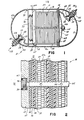
- Fig. 1 is an axial section of a preferred form of metal-gas battery according to the present invention;
- Fig. 2 is a detailed cross section of a portion of the cell stack of a battery in accordance with the present invention;
- Fig. 3 is a plan view of a weld ring for use in the battery of the present invention; and
- Fig. 4 is a disassembled side view of the positive end plate and reservoir of the plate stack.
- A metal-gas cell, hereinafter described as a nickel-hydrogen cell, includes a cell or plate stack which is a plurality of alternating negative and positive electrodes connected to negative and positive bus bars, respectively. The bus bars in turn are connected to terminals which extend through the cell casing which contains the pressurized operating gas within the cell.
- In Fig. 1 there is shown a nickel-
hydrogen cell 10 including anexternal casing 11. The casing is preferably made from a hard metal such as Inconel 718, an alloy principally composed of 52% nickel, 19% chromium and 18.5% iron, and which is produced by the International Nickel Company. The casing is a two-section casing. One section 12 comprises acylindrical center portion 12a and adomed end portion 12b. The second section of the casing is an opposingdomed end portion 13. The twosections 12 and 13 are welded together at and through anInconel weld ring 14. - Within the cell casing is a
plate stack 16 formed from a plurality of alternatingnegative electrodes 18 andpositive electrodes 20. The electrodes are in turn electrically connected to negative andpositive bus bars - More particularly, the plate stack is formed from a plurality of layers as shown in detail in Fig. 2. The cell stack begins with a
positive end plate 30 adjacent agas spacer 32 such as a polypropylene mesh material which in turn contacts the laminatednegative electrode 18 formed from a support lamina of Teflonbacking material 34 and a platinum active lamina orface 36. Thenegative electrode 18 is separated from apositive electrode 20 by anasbestos separator 38. Adjacent thepositive electrode 20 is a second positive electrode 20a, separated from a secondnegative electrode 19 by anotherasbestos separator 38. This configuration is repeated throughout the cell stack providing as many negative and positive electrodes as desired. Typically, such a plate stack would include 14 pairs of positive electrodes and 28 individual negative electrodes. The plate stack ends with a negative end plate 40 (see Fig. 1); The individual layers of the plate stack are maintained in facial contact with one another between the positive andnegative end plates 30 and 40, respectively. - The bus bars provide a complete electrical path from the negative to the positive terminal of the battery, preferably through the plate stack. As shown in Fig. 1, the
bent portions bus bars inner ends 46 and 48 of terminals 26 and 28. The terminals extend through openings in therespective domed ends conical portion 50 which as the terminal is drawn up bynuts 52 compresses correspondingly tapered plastic "Teflon"primary seals 55 andsecondary seals 54. Theseals Inconel sleeve 58 which is welded to the domed ends. - The
plate stack 16 is maintained under compression by means supported by the cell casing. As shown more particularly in Fig. 1, the plate stack is held compressed between thepositive end plate 30 and the negative end plate 40. The positive end plate as shown in Fig. 4 includes aplanar plate section 60 and an axially extending tubular section orcore 62. Thecore 62 is hollow throughout its entire length in the stack, except at threadedend 64. A plurality oftransverse ports 66 extend from the core to the hollow interior. Theplanar plate section 60 of the positive end plate includes a central internally threadedopening 67 communicating with the hollow interior ofthe.core 62 so as to provide a fluid path from the positive end plate through the core and through theports 66. - The negative end plate 40 rests against
weld ring 14. As shown in Fig. 3, the weld ring is an annular ring including acentral hub 14a and axially extending spokes 14b.Hub 14a further includes acentral aperture 14c to allow the core 62 to pass through. Thepositive end plate 30 is positioned at the end of the cell stack opposite the negative end plate 40 with the core 62 extending through theplate stack 16 through the negative end plate 40 andcentral aperture 14c ofweld ring 14. The core finally extends through a Belleville washer 68.Nut 70 screwed onto the threadedend 64 of thecore 62 holds the cell stack compressed against the weld ring. The Belleville washer acts as a spring maintaining a compressing force on the cell stack which permits the cell stack to grow or expand during charging and discharging. - Further as shown in Fig. 1, the battery includes an
electrolyte reservoir 72. The reservoir is a flexible sealed chamber or bladder having an externally threadedport 74 which threads into the internally threadedopening 67 of thepositive end plate 30. The opposite end of the reservoir is a flatplanar disc 76 which abuts the cell casing at anannular indent 78. Thereservoir 72 is a flexible material, preferably thin flexible stainless steel. - As constructed, the
electrolyte reservoir 72 is positioned and is held in the battery casing with itsend plate 76 resting againstindent 78. Threadedport 74 is screwed into internally threadedopening 67 in the positive end plate. Preferably, an O-ring 79 is used to maintain a seal between the reservoir and the positive end plate. Thecore 62 of thepositive end plate 30 then extends through theplate stack 16 through the negative end plate 40, theweld ring 14 and Belleville washer 68 to which it is secured by anut 70. Since theweld ring 14 is welded to the casing, both the negative end plate 40 and the Belleville washer 68 are held in a fixed or immovable position relative to the casing. - During operation or use, the repeated charging and discharging of the cell will cause the plate stack to grow or expand in volume. Due to the construction of the battery with the plate stack held compressed by a Belleville washer which yieldably biases the positive end plate toward the negative end plate, the plate stack is permitted to expand and grow. As the plate stack grows in length, the
positive end plate 30 will move towards theplate 76 of thereservoir 72 as shown by ΔX in Figure 1. This in turn will compress the reservoir, forcing electrolyte stored in the reservoir through the positive end plate into the hollow interior of thecore 62. This electrolyte will then pass through the core to the cell stack throughindividual ports 66. Thus,core 62 is an electrolyte distribution tube or means. Preferably, theports 66 should be located in the area of thepositive electrodes 20. Accordingly, as the plate stack grows, additional electrolyte is provided at the positive electrodes maintaining the plate stack properly wetted with electrolyte even though the volume increases. - The preceding was a disclosure of the preferred embodiment of the present invention. The disclosed cell can be modified and yet still incorporate the present invention. For example, two reservoirs could be used, one positioned at each end of the plate stack, or the reservoir could be positioned within the plate stack. Instead of compressible bladder, the electrolyte reservoir can alternately be a large spongelike or felt disc encased in plastic. This construction would be lighter than using a stainless steel bladder.
Claims (8)
Applications Claiming Priority (2)
| Application Number | Priority Date | Filing Date | Title |
|---|---|---|---|
| US06/538,088 US4477540A (en) | 1983-10-03 | 1983-10-03 | Metal-gas cell with electrolyte reservoir |
| US538088 | 1983-10-03 |
Publications (2)
| Publication Number | Publication Date |
|---|---|
| EP0136769A2 true EP0136769A2 (en) | 1985-04-10 |
| EP0136769A3 EP0136769A3 (en) | 1986-10-08 |
Family
ID=24145437
Family Applications (1)
| Application Number | Title | Priority Date | Filing Date |
|---|---|---|---|
| EP84302828A Withdrawn EP0136769A3 (en) | 1983-10-03 | 1984-04-26 | Metal-gas cell with electrolyte reservoir |
Country Status (4)
| Country | Link |
|---|---|
| US (1) | US4477540A (en) |
| EP (1) | EP0136769A3 (en) |
| JP (1) | JPS6081780A (en) |
| CA (1) | CA1215111A (en) |
Cited By (3)
| Publication number | Priority date | Publication date | Assignee | Title |
|---|---|---|---|---|
| EP0340963A2 (en) * | 1988-05-02 | 1989-11-08 | Saft America Inc. | Metal gas cell |
| EP0449511A2 (en) * | 1990-03-30 | 1991-10-02 | Communications Satellite Corporation | Battery |
| US5354630A (en) * | 1992-12-10 | 1994-10-11 | Comsat | Ni-H2 battery having improved thermal properties |
Families Citing this family (18)
| Publication number | Priority date | Publication date | Assignee | Title |
|---|---|---|---|---|
| US4546054A (en) * | 1985-02-22 | 1985-10-08 | Eagle-Picher Industries, Inc. | Support assembly for cells of a secondary battery |
| US5002842A (en) * | 1988-05-02 | 1991-03-26 | Gates Energy Products, Inc. | End plate for a metal gas cell |
| US5030524A (en) * | 1989-01-19 | 1991-07-09 | Hughes Aircraft Company | Battery cell stack having extended life |
| US4950565A (en) * | 1989-11-09 | 1990-08-21 | Honeywell Inc. | Reserve activated electrochemical cell |
| US5082754A (en) * | 1990-05-24 | 1992-01-21 | Globe-Union Inc. | Pressure vessel construction for a metal oxide-hydrogen battery |
| US5162171A (en) * | 1991-10-28 | 1992-11-10 | Globe-Union Inc. | Metal oxide-hydrogen battery having modules extending longitudinally of the pressure vessel |
| US5168017A (en) * | 1991-10-28 | 1992-12-01 | Globe-Union Inc. | Metal oxide-hydrogen battery having rectangular modules in a cylindrical pressure vessel |
| US5173377A (en) * | 1991-10-28 | 1992-12-22 | Globe-Union Inc. | Apparatus for electrically connecting cell modules of a metal oxide-hydrogen battery |
| US5173376A (en) * | 1991-10-28 | 1992-12-22 | Globe-Union Inc. | Metal oxide hydrogen battery having sealed cell modules with electrolyte containment and hydrogen venting |
| US5306579A (en) * | 1992-10-30 | 1994-04-26 | Aer Energy Resources, Inc. | Bifunctional metal-air electrode |
| IL105688A (en) * | 1993-05-13 | 1996-09-12 | Erez Mordechai | Electrochemical cell |
| US6200698B1 (en) * | 1999-08-11 | 2001-03-13 | Plug Power Inc. | End plate assembly having a two-phase fluid-filled bladder and method for compressing a fuel cell stack |
| US20030008192A1 (en) * | 2001-04-10 | 2003-01-09 | Freund Michael S. | Actuatable and reversible pressure generation based on fuel cell operation |
| DE102008043808A1 (en) * | 2008-11-18 | 2010-05-20 | Robert Bosch Gmbh | battery |
| US8808914B2 (en) | 2012-01-13 | 2014-08-19 | Energy Power Systems, LLC | Lead-acid battery design having versatile form factor |
| US9595360B2 (en) | 2012-01-13 | 2017-03-14 | Energy Power Systems LLC | Metallic alloys having amorphous, nano-crystalline, or microcrystalline structure |
| US9263721B2 (en) | 2012-01-13 | 2016-02-16 | Energy Power Systems LLC | Lead-acid battery design having versatile form factor |
| DE102022001427B3 (en) | 2022-04-25 | 2023-06-29 | Mercedes-Benz Group AG | Method of introducing electrolyte |
Citations (5)
| Publication number | Priority date | Publication date | Assignee | Title |
|---|---|---|---|---|
| FR1211799A (en) * | 1957-10-09 | 1960-03-18 | Union Carbide Corp | Dry battery |
| FR2115211A1 (en) * | 1970-11-19 | 1972-07-07 | Honeywell Inc | |
| US4038461A (en) * | 1976-01-28 | 1977-07-26 | The United States Of America As Represented By The Secretary Of The Air Force | Electrochemical cell having balanced distribution of oxygen and electrolyte |
| US4098962A (en) * | 1977-04-14 | 1978-07-04 | Yardney Electric Corporation | Metal-hydrogen secondary battery system |
| US4327158A (en) * | 1980-08-15 | 1982-04-27 | Eic Laboratories, Inc. | Metal/gas battery |
Family Cites Families (7)
| Publication number | Priority date | Publication date | Assignee | Title |
|---|---|---|---|---|
| US3716708A (en) * | 1970-08-17 | 1973-02-13 | Mallory & Co Inc P R | Flashlight with reserve cell |
| US3867199A (en) * | 1972-06-05 | 1975-02-18 | Communications Satellite Corp | Nickel hydrogen cell |
| US3975210A (en) * | 1975-03-27 | 1976-08-17 | The United States Of America As Represented By The Secretary Of The Air Force | Metal-gas battery with axial reactant gas storage cavity |
| US4115630A (en) * | 1977-03-17 | 1978-09-19 | Communications Satellite Corporation | Metal-hydrogen battery |
| US4188462A (en) * | 1978-10-30 | 1980-02-12 | The Continental Group, Inc. | Power module assembly with monopolar cells |
| US4177328A (en) * | 1978-12-19 | 1979-12-04 | The United States Of America As Represented By The Secretary Of The Air Force | Wall wick for nickel-hydrogen cell |
| US4389466A (en) * | 1981-06-03 | 1983-06-21 | The United States Of America As Represented By The United States Department Of Energy | Rapidly refuelable fuel cell |
-
1983
- 1983-10-03 US US06/538,088 patent/US4477540A/en not_active Expired - Lifetime
-
1984
- 1984-04-13 CA CA000451938A patent/CA1215111A/en not_active Expired
- 1984-04-26 EP EP84302828A patent/EP0136769A3/en not_active Withdrawn
- 1984-06-14 JP JP59122875A patent/JPS6081780A/en active Pending
Patent Citations (5)
| Publication number | Priority date | Publication date | Assignee | Title |
|---|---|---|---|---|
| FR1211799A (en) * | 1957-10-09 | 1960-03-18 | Union Carbide Corp | Dry battery |
| FR2115211A1 (en) * | 1970-11-19 | 1972-07-07 | Honeywell Inc | |
| US4038461A (en) * | 1976-01-28 | 1977-07-26 | The United States Of America As Represented By The Secretary Of The Air Force | Electrochemical cell having balanced distribution of oxygen and electrolyte |
| US4098962A (en) * | 1977-04-14 | 1978-07-04 | Yardney Electric Corporation | Metal-hydrogen secondary battery system |
| US4327158A (en) * | 1980-08-15 | 1982-04-27 | Eic Laboratories, Inc. | Metal/gas battery |
Cited By (5)
| Publication number | Priority date | Publication date | Assignee | Title |
|---|---|---|---|---|
| EP0340963A2 (en) * | 1988-05-02 | 1989-11-08 | Saft America Inc. | Metal gas cell |
| EP0340963A3 (en) * | 1988-05-02 | 1991-07-03 | Saft America Inc. | Metal gas cell |
| EP0449511A2 (en) * | 1990-03-30 | 1991-10-02 | Communications Satellite Corporation | Battery |
| EP0449511A3 (en) * | 1990-03-30 | 1992-05-27 | Communications Satellite Corporation | Battery |
| US5354630A (en) * | 1992-12-10 | 1994-10-11 | Comsat | Ni-H2 battery having improved thermal properties |
Also Published As
| Publication number | Publication date |
|---|---|
| EP0136769A3 (en) | 1986-10-08 |
| US4477540A (en) | 1984-10-16 |
| CA1215111A (en) | 1986-12-09 |
| JPS6081780A (en) | 1985-05-09 |
Similar Documents
| Publication | Publication Date | Title |
|---|---|---|
| US4477540A (en) | Metal-gas cell with electrolyte reservoir | |
| EP0039557B1 (en) | Electrochemical cell | |
| EP0187145B1 (en) | Nickel-hydrogen bipolar battery | |
| US6080501A (en) | Fuel cell with integral fuel storage | |
| US3867199A (en) | Nickel hydrogen cell | |
| US4112199A (en) | Lanthanum nickel hydride-hydrogen/metal oxide cell | |
| US5532074A (en) | Segmented hydride battery | |
| US3850694A (en) | Low pressure nickel hydrogen cell | |
| US4127703A (en) | Nickel-hydrogen secondary battery | |
| EP0290764B1 (en) | Cylindrical bipolar electrode battery | |
| RU2075139C1 (en) | Sealed galvanic one-time or re-usable element | |
| US3959018A (en) | Low pressure nickel hydrogen cell | |
| US3650837A (en) | Secondary metal/air cell | |
| EP0188873B1 (en) | Lightweight bipolar metal-gas battery | |
| US5047301A (en) | High temperature battery and system utilizing same | |
| US4517264A (en) | Lightweight metal-hydrogen cell with improved plate stack supporting means | |
| US4546054A (en) | Support assembly for cells of a secondary battery | |
| US4467020A (en) | Rechargeable lead-hydrogen electrochemical cell | |
| US3713892A (en) | Method of charging secondary metal-air cell | |
| US3759748A (en) | Electrically recharged metal air cell | |
| US4031296A (en) | Electrochemical energy cell | |
| US4283468A (en) | Electrochemical cell insensitive to physical orientation | |
| US5389459A (en) | Distributed energy system | |
| US4142025A (en) | Sealed nickel cadmium battery capable of withstanding high rate overdischarge | |
| US4074018A (en) | Secondary fuel cell |
Legal Events
| Date | Code | Title | Description |
|---|---|---|---|
| PUAI | Public reference made under article 153(3) epc to a published international application that has entered the european phase |
Free format text: ORIGINAL CODE: 0009012 |
|
| AK | Designated contracting states |
Designated state(s): BE DE FR GB IT LU NL SE |
|
| PUAL | Search report despatched |
Free format text: ORIGINAL CODE: 0009013 |
|
| AK | Designated contracting states |
Kind code of ref document: A3 Designated state(s): BE DE FR GB IT LU NL SE |
|
| 17P | Request for examination filed |
Effective date: 19861215 |
|
| 17Q | First examination report despatched |
Effective date: 19880603 |
|
| STAA | Information on the status of an ep patent application or granted ep patent |
Free format text: STATUS: THE APPLICATION HAS BEEN WITHDRAWN |
|
| 18W | Application withdrawn |
Withdrawal date: 19880810 |
|
| ITF | It: translation for a ep patent filed |
Owner name: STUDIO JAUMANN |
|
| RIN1 | Information on inventor provided before grant (corrected) |
Inventor name: MILLER, LEE E. Inventor name: CARR, DENNIS D. |