EP0136212A1 - Apparatus and method for the indirect measurement of arterial blood pressure - Google Patents
Apparatus and method for the indirect measurement of arterial blood pressure Download PDFInfo
- Publication number
- EP0136212A1 EP0136212A1 EP84401631A EP84401631A EP0136212A1 EP 0136212 A1 EP0136212 A1 EP 0136212A1 EP 84401631 A EP84401631 A EP 84401631A EP 84401631 A EP84401631 A EP 84401631A EP 0136212 A1 EP0136212 A1 EP 0136212A1
- Authority
- EP
- European Patent Office
- Prior art keywords
- pressure
- value
- force
- average
- calculation means
- Prior art date
- Legal status (The legal status is an assumption and is not a legal conclusion. Google has not performed a legal analysis and makes no representation as to the accuracy of the status listed.)
- Ceased
Links
Images


Classifications
-
- A—HUMAN NECESSITIES
- A61—MEDICAL OR VETERINARY SCIENCE; HYGIENE
- A61B—DIAGNOSIS; SURGERY; IDENTIFICATION
- A61B5/00—Measuring for diagnostic purposes; Identification of persons
- A61B5/02—Detecting, measuring or recording pulse, heart rate, blood pressure or blood flow; Combined pulse/heart-rate/blood pressure determination; Evaluating a cardiovascular condition not otherwise provided for, e.g. using combinations of techniques provided for in this group with electrocardiography or electroauscultation; Heart catheters for measuring blood pressure
- A61B5/021—Measuring pressure in heart or blood vessels
- A61B5/02108—Measuring pressure in heart or blood vessels from analysis of pulse wave characteristics
- A61B5/02116—Measuring pressure in heart or blood vessels from analysis of pulse wave characteristics of pulse wave amplitude
-
- A—HUMAN NECESSITIES
- A61—MEDICAL OR VETERINARY SCIENCE; HYGIENE
- A61B—DIAGNOSIS; SURGERY; IDENTIFICATION
- A61B5/00—Measuring for diagnostic purposes; Identification of persons
- A61B5/68—Arrangements of detecting, measuring or recording means, e.g. sensors, in relation to patient
- A61B5/6801—Arrangements of detecting, measuring or recording means, e.g. sensors, in relation to patient specially adapted to be attached to or worn on the body surface
- A61B5/6843—Monitoring or controlling sensor contact pressure
-
- A—HUMAN NECESSITIES
- A61—MEDICAL OR VETERINARY SCIENCE; HYGIENE
- A61B—DIAGNOSIS; SURGERY; IDENTIFICATION
- A61B2560/00—Constructional details of operational features of apparatus; Accessories for medical measuring apparatus
- A61B2560/04—Constructional details of apparatus
- A61B2560/0406—Constructional details of apparatus specially shaped apparatus housings
- A61B2560/0418—Pen-shaped housings
Definitions
- the present invention relates to an apparatus and method for measuring blood pressure by an indirect, non-bloody method (i.e., without the introduction of a catheter).
- the classic procedure for determining blood pressure known as RIVA-ROCCI, consists of blocking part of the patient's circulatory system by exerting pressure on his arm greater than the systolic pressure in order to prevent blood from flowing to forearm, then release this pressure very slowly by reading the two values for which the KOROTKOV noises appear, become muffled, then disappear on a manometer.
- a first drawback of this method is that it requires, in addition to a stethoscope, a bulky inflatable cuff whose dimensions must be adapted to the size of the arm.
- a second drawback of this method is that the relationship between diastolic pressure, which is however the most representative of the patient's circulatory state, and the deafening or total disappearance of KOROTKOV noises is very controversial in the medical community.
- a third drawback of this method is that the parasitic noises emitted in the room or caused by a movement of the patient make listening to KOROTKOV noises very delicate and require an operator experimented.
- the main object of the invention is to eliminate all these drawbacks as far as possible and to allow everyone to measure diastolic and systolic pressures on themselves as easily as on someone else, and incidentally the average pressure and heart rate, with reliability hitherto reserved for experienced specialists, and this without ever interrupting blood flow, unlike all existing devices and methods that interrupt blood flow completely, then partially for many seconds.
- the device also comprises or be associated with it means of analysis of the shape of the instantaneous variation of the arterial pressure, these means of analysis having their output connected to a control input of the second storage means so as to control the storage of the force F exerted by the force sensor.
- the device object of the present invention can. when it is pressed on said artery with a force greater than that exerted by the systolic pressure of the blood flow and when this bearing force is then progressively reduced until it is canceled. analyze the amplitude of the oscillations to determine the systolic pressure and the diastolic pressure of the blood flow using the well-known method of oscillometry.
- the device can be provided with one of the gripping and suspension devices well known to those skilled in the art and not shown here, allowing the two sensors to be pressed with the same progressively increasing or gradually decreasing force. while 1 user of the device exerts a constant or zero force.
- the apparatus of the invention can therefore be used by anyone. even inexperienced.
- At least two force sensors are used which are arranged one after the other in the pulse gutter along the radial artery, and the signals supplied by these two sensors to determine that the support force is less than or respectively at least equal to the force created by the diastolic pressure of the blood flow of the radial artery depending on whether the signals supplied are identical or respectively different.
- the invention is based on the measurement of the force exerted on the membranes of two dynamometers, on the one hand, by the user of the device pressing it on the radial artery in the gutter of the pulse, on the other part, by the pulsatile wave of the arterial flow through the wall of said artery; more precisely, it is based on the analysis of the shape of the two measurements of these forces at two neighboring points as do the two fingers of the practitioner palpating the radial artery in the groove of the pulse, but this statistically from the sampled values of the measurement provided by the dynamometers.
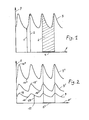
- FIG. 1 represents the evolution, as a function of the current time along axis 6, of an example of four arterial pressure cycles 3 carried along axis 7.
- Amplitude 1 represents the minimum pressure or diastolic pressure P D.
- amplitude 2 represents the maximum pressure or systolic pressure P S.
- the segment 5 represents the magnitude T of a period of the cardiac cycle.
- the average pressure P is obtained by dividing 1 area 4 by the segment 5. In the rest of this description. we will call M the PM / PD ratio.
- Figure 2 shows the evolution. as a function of the current time along axis 6 ; . of an example of the tensions (expressed in volts) carried along 1 axis 8 supplied by one of the dynamometers used to detect the arterial pressure.
- the tension 9 is obtained for a very weak force of support.
- the tension 9 ' is obtained for a pressing force double the previous one.
- the tension 9 " is obtained for a support force four times the first.
- the voltages supplied by the second dynamometer do not are not shown. but they are exactly identical to the voltages 9. 9 'and 9 "with an offset near n ⁇ along the axis 6' of a few sampling periods ⁇ which are taken into account by the electronics.
- segment 5 ′ is identical to the segment 5 of FIG. 1 and that it has a magnitude equal to T.
- FIG. 3 represents a side view of a preferred embodiment of the apparatus according to the invention which has the shape of a parallelepided 15 with rounded edges which may for example be about 8 cm long and a section 1 cm by 2 cm.
- the end 18 is slightly curved and comprises, aligned one in the extension of the other a few millimeters apart, two keys 19 and 20 of about 1 cm in diameter, only revealing the membranes of two dynamometers through with a rectangular opening of 0.4 cm by 0.8 cm approximately.
- the other end is constituted by a display 17 of at least five alphanumeric characters. a display 17 and a display 17 "of at least 1 character each.
- the body 16 of the device contains an electric battery. a switch energizing 1 device when it is clamped between the thumb and 1 user's index finger. and the electronics required for operation
- Figure 4 shows the display 17. and the 17 'and 17 "displays viewed from the front.
- the + 00 / MN + display shown here is the one it provides when the device is switched on before it is supported on the radial artery.
- FIG. 1 represents the evolution, as a function of the current time along axis 6, of an example of four arterial pressure cycles 3 carried along axis 7.
- Amplitude 1 represents the minimum pressure or diastolic pressure P D.
- amplitude 2 represents the maximum pressure or systolic pressure P S.
- the segment 5 represents the magnitude T of a period of the cardiac cycle.
- the average pressure P m is obtained by dividing 1 area 4 by the segment 5. In the remainder of this description, M will be called the ratio P M / P D.
- Figure 2 shows the evolution. as a function of the current time along axis 6 '. of an example of the voltages (expressed in volts) carried along 1 axis 8 supplied by one of the dynamometers used to detect the arterial pressure.
- the tension 9 is obtained for a very low pressing force.
- the tension 9 ' is obtained for a double pressing force of the previous one.
- the 9 "tension is obtained for a quadruple pressing force of the first.
- the voltages supplied by the second dynamometer do not are not shown, but they are exactly identical to the voltages 9. 9 'and 9 "with an offset near n ⁇ along the axis 6' of some sampling periods ⁇ which are taken into account by the electronics.
- segment 5 ′ is identical to the segment 5 of FIG. 1 and that it has a magnitude equal to T.
- FIGS. 1 and 2 which is the basis of the present invention. that the ratio of the amplitudes 2 and 1. that is to say P S / P D of FIG. 1 and which will be designated by R in the rest of this description. is practically equal to the ratios of the amplitudes 12/10. 12 '/ 10' and 12 "/ 10" from the maxima to the minima of the tensions 9. 9 'and 9 ".
- FIG. 3 represents a side view of a preferred embodiment of the apparatus according to the invention which has the shape of a parallelepided 15 with rounded edges which may for example be about 8 cm long and a section 1 cm by 2 cm.
- the end 18 is slightly curved and comprises, aligned one in the extension of the other a few millimeters apart, two keys 19 and 20 of about 1 cm in diameter, only revealing the membranes of two dynamometers through with a rectangular opening of 0.4 cm by 0.8 cm approximately.
- the other end is constituted by a display 17 of at least five alphanumeric characters, a display 17 'and a display 17 "of at least 1 character each.
- the body 16 of the device contains an electric battery, a switch putting 1 device on when it is clamped between the thumb and 1 index finger of the user. and the electronics required for operation
- Figure 4 shows the display 17. and the 17 'and 17 "displays viewed from the front.
- the + 00 / MN + display shown here is the one it provides when the device is switched on before it is supported on the radial artery.
- Figure 5 shows the device seen from below showing the body 18 containing the dynamometers and their two keys 19 and 20.
- FIG. 6 shows an example, in the form of a block diagram, of the general structure of a preferred embodiment of the apparatus of the invention and of the sequence of operations carried out on the voltages V1 and V2 supplied by the dynamometers assuming that the latter give a continuous analog voltage, under the control of the clock H, before reaching the display 17.
- the voltage V1 of the first dynamometer provided with the key 19 is sampled and digitized, and sent to an input of the comparator 24 and to an input of the adder 25.
- the voltage V2 of the second dynamometer provided with the key 20 is, thanks to block 22, sampled and digitized, and sent to the other input of comparator 24 and to the other input of adder 25.
- the output of block 24 represents the likelihood test which controls, on the one hand, the memorization of the force F in block 26 whose output is the diastolic pressure PD, on the other hand, the control logic 42 of the display 17 and. on the other hand. the 17 'and 17 "displays.
- the output of block 25 represents, to the nearest digit, the average of V1 and V2, that is to say Vm.
- Block 27 performs the search for the maxima of Vm which are stored in block 28, and totalized in block 29 which performs the operation N ⁇ 1 Vmax, the result of which is sent to the divider 33.
- Block 30 performs the search for minima of Vm which are stored in block 31, and totalized in block 32 which performs the operation N ⁇ 1 Vmin, the result is also sent to divisor 33.
- This block 33 performs the division of N ⁇ 1 Vmax by N ⁇ 1 Vmin whose result, Rmoyen, is sent to the multiplier 34.
- Block 35 accumulates the increments of the clock H under the control of the Vmax identified by block 27; it therefore provides the period T which, thanks to block 41, is inverted and multiplied by 60 to give the heart rate XX / MN which is sent to the control logic 42 of the display 17.
- Block 36 totals the values of Vm for a whole period T, which represents the value of the hatched area 4 of FIG. 1.
- the value of the hatched area 4 is divided in block 37 by the value of the Vmin of the period considered and by the period T itself, and the result, which is the ratio M, is stored in block 38 .
- Block 39 calculates the average coefficient by performing the 1N N ⁇ 1 operation and block 40 performs the multiplication of Average by the output of block 26 which is the diastolic pressure P D , which gives the average pressure P M which is sent to the control logic 42 of the display 17.
- Block 34 which performs the multiplication of R mean from block 33 by the diastolic pressure P D supplies the systolic pressure P s to the control logic 42.
- control logic 42 under the control of the likelihood test coming from block 24, sends to the display 17 either the heart rate, or P S and PD, or the average pressure P M.
- the display shows + 00 / MN + (see figure 4).
- the equipment then detects a third maximum and calculates a second period T2. a second report R2 and a second report M2.
- the device then detects a fourth maximum and calculates a third period T3, a third report R3 and a third report M3. and so on for N cardiac cycles without interfering in any way with the passage of blood flow.
- the two + signs continue to be displayed. Otherwise, one of the + turns into -. prompting the user to press less on this side of the device.
- T2 is used to calculate the new heart rate transmitted to the display for half a period.
- T3 which is used to calculate the new heart rate transmitted to the display for half a period.
- the ratio R is identical to the ratio existing between the systolic and diastolic pressures as long as the compressive force applied to the external wall of the artery is less than the diastolic pressure.
- the dynamometers used will preferably provide digital information and that this will advantageously be processed by semiconductor circuits of the microprocessor type of current use today.
- the apparatus which is the subject of the present invention can receive numerous modifications both in the number of dynamometers and in their type and in the way of processing and presenting their signals, that in the presentation of the device whose displays 17. 17. and 17 "or the body 16 can be offset at the end of a cord, be connected to the end 18 by an elastic or articulated device, remotely transmit the measure or be replaced by a voice device, or take the average of the measurements made over a given period of time, for example a day, in order to monitor hypertensive patients and adjust their anti-hypertensive treatment. 'invention.
- the apparatus of the invention can be adapted for the implementation of a measurement method called the oscillometric method.
- the device is arranged as shown in Figure 7 in which the elements identical to those of Figure 6 are designated using the same reference numerals.
- Block 43 subtracts from each cycle the last MIN from the last MAX and therefore gives the amplitude of the pulsation.
- Block 44 calculates the slope of the variation of this amplitude and controls blocks 45. 46 and 47. which memorize the forces corresponding respectively to the systolic pressure P S , at the diastolic pressure P D , and at the average pressure P M '
Abstract
L'invention vise à mesurer par voie externe la pression artérielle d'un patient en utilisant au moins un capteur de force (19) destiné à être tenu en appui dans la gouttière du pouls avec une force constante inférieure à celle créée par la pression diastolique du flux sanguin de l'artère radiale, en détectant (21, 25, 27, 30) les maxima et les minima des signaux de pression, en calculant (29, 32, 33) la moyenne des rapaports R de ces maxima et minima, en augmentant la force d'appui jusqu'à perturber le flux sanguin (pression diastolique PD), en calculant la pression systolique PS = PD x Rm et en affichant (17) les valeurs PS et PD.The invention aims to measure the arterial pressure of a patient externally by using at least one force sensor (19) intended to be held in abutment in the pulse channel with a constant force less than that created by the diastolic pressure. of the radial artery blood flow, by detecting (21, 25, 27, 30) the maxima and minima of the pressure signals, by calculating (29, 32, 33) the average of the ratios R of these maxima and minima, by increasing the pressing force until disturbing the blood flow (diastolic pressure PD), by calculating the systolic pressure PS = PD x Rm and by displaying (17) the values PS and PD.
Description
La présente invention concerne un appareil et un procédé de mesure de la tension artérielle suivant une méthode indirecte, non sanglante (c'est-à-dire, par exemple, sans introduction de cathéter). Le mode opératoire classique de détermination de la tension artérielle, dit de RIVA-ROCCI, consiste à bloquer une partie du système circulatoire du malade en exerçant sur son bras une pression supérieure à la pression systolique afin d'empêcher le sang de s'écouler vers l'avant-bras, puis à relâcher très lentement cette pression en relevant sur un manomètre les deux valeurs pour lesquelles les bruits de KOROTKOV apparaissent, s'assourdissent, puis disparaissent.The present invention relates to an apparatus and method for measuring blood pressure by an indirect, non-bloody method (i.e., without the introduction of a catheter). The classic procedure for determining blood pressure, known as RIVA-ROCCI, consists of blocking part of the patient's circulatory system by exerting pressure on his arm greater than the systolic pressure in order to prevent blood from flowing to forearm, then release this pressure very slowly by reading the two values for which the KOROTKOV noises appear, become muffled, then disappear on a manometer.
Lorsque les bruits apparaissent, on note la pression de crête ou pression systolique ; lorsque les bruits dispa- raissent, on note la pression minimale ou pression diastolique.When the noises appear, we note the peak pressure or systolic pressure; when the noise disap - raissent, there is the minimum or diastolic pressure.
Un premier inconvénient de cette méthode est qu'elle nécessite, en plus d'un stéthoscope, un brassard gonflable encombrant dont les dimensions doivent être adaptées à la grosseur du bras.A first drawback of this method is that it requires, in addition to a stethoscope, a bulky inflatable cuff whose dimensions must be adapted to the size of the arm.
Un deuxième inconvénient de cette méthode est que la relation entre la pression diastolique, qui est pourtant la plus représentative de l'état circulatoire du malade, et l'assourdissement ou la disparition totale des bruits de KOROTKOV est très controversée dans le milieu médical.A second drawback of this method is that the relationship between diastolic pressure, which is however the most representative of the patient's circulatory state, and the deafening or total disappearance of KOROTKOV noises is very controversial in the medical community.
Un troisième inconvénient de cette méthode est que les bruits parasites émis dans la pièce ou provoqués par un mouvement du patient rendent l'écoute des bruits de KOROTKOV très délicate et nécessitent un opérateur expérimenté.A third drawback of this method is that the parasitic noises emitted in the room or caused by a movement of the patient make listening to KOROTKOV noises very delicate and require an operator experimented.
De nombreux perfectionnements ont été proposés, consistant essentiellement à rendre automatiques le gonflage du brassard, ta mesure de la pression, ou l'analyse des bruits, comme par exemple le brevet FR 75 05046 (publié sous le n° 2.260.975), mais ils conduisent généralement à un appareillage lourd, encombrant, et aléatoire.Numerous improvements have been proposed, essentially consisting in making automatic the inflation of the cuff, the measurement of the pressure, or the analysis of the noises, such as for example the patent FR 75 05046 (published under the number 2.260.975), but they generally lead to heavy, bulky and random equipment.
L'invention a essentiellement pour but de supprimer tous ces inconvénients dans toute la mesure du possible et de permettre à tout un chacun de mesurer sur lui-même aussi facilement que sur quelqu'un d'autre les pressions diastolique et systolique, et accessoirement la pression moyenne et le rythme cardiaque, avec une fiabilité réservée jusqu'ici aux spécialistes expérimentés, et cela sans jamais interrompre le flux sanguin, contrairement à tous les appareils et procédés existants qui interrompent le flux sanguin totalement, puis partiellement pendant de nombreuses secondes.The main object of the invention is to eliminate all these drawbacks as far as possible and to allow everyone to measure diastolic and systolic pressures on themselves as easily as on someone else, and incidentally the average pressure and heart rate, with reliability hitherto reserved for experienced specialists, and this without ever interrupting blood flow, unlike all existing devices and methods that interrupt blood flow completely, then partially for many seconds.
A ces fins, selon un premier de ses aspects qui est relatif à un appareil pour mesurer la tension artérielle, l'invention prévoit que ledit appareil comprend :
- - au moins un capteur de force destiné, en fonctionnement, à être tenu en appui dans la gouttière du pouls avec une force sensiblement constante inférieure à celle créée par la pression diastolique du flux sanguin de l'artère radiale,
- - des moyens de détection connectés au susdit capteur de force et agencés pour détecter les maxima et les minima des signaux de sortie du capteur de force,
- - des premiers moyens de mémorisation connectés auxdits moyens de détection et agencés pour mémoriser lesdits maxima et lesdits minima,
- - des premiers moyens de calcul connectés auxdits premiers moyens de mémorisation et agencés pour calculer respectivement la somme des maxima du signal de pression et la somme des minima du signal de pression,
- - des deuxièmes moyens de calcul connectés aux premiers moyens de calcul et agencés pour calculer la valeur moyenne Rm du rapport de la somme des maxima du signal de pression à la somme des minima du signal de pression,
- - des deuxièmes moyens de mémorisation connectés au capteur de force et agencés pour mémoriser la valeur de la force d'appui correspondant à l'amorce de la perturbation du flux sanguin, cette force étant considérée comme la pression diastolique PD,
- - des troisièmes moyens de calcul connectés aux deuxièmes moyens de mémorisation et aux deuxièmes moyens de calcul et agencés pour calculer la valeur Ps du produit de la susdite valeur PD par la susdite valeur Rm,
- - et des moyens d'affichage connectés auxdits troisièmes moyens de calcul et aux deuxièmes moyens de mémorisation et agencés pour afficher, simultanément et dans l'ordre, les valeurs Ps et P D.
- - at least one force sensor intended, in operation, to be held in abutment in the pulse gutter with a substantially constant force less than that created by the diastolic pressure of the blood flow of the radial artery,
- - detection means connected to the above force sensor and arranged to detect the maximums and minimums of the output signals from the force sensor,
- first storage means connected to said detection means and arranged to store said maxima and said minima,
- first calculation means connected to said first storage means and arranged to respectively calculate the sum of the maxima of the pressure signal and the sum of the minima of the pressure signal,
- second calculation means connected to the first calculation means and arranged to calculate the average value R m of the ratio of the sum of the maxima of the pressure signal to the sum of the minima of the pressure signal,
- second storage means connected to the force sensor and arranged to store the value of the support force corresponding to the onset of the disturbance of the blood flow, this force being considered as the diastolic pressure P D ,
- - third calculation means connected to the second storage means and to the second calculation means and arranged to calculate the value P s of the product of the above value P D by the above value R m ,
- - And display means connected to said third calculation means and to the second storage means and arranged to display, simultaneously and in order, the values P s and P D.
Il peut être avantageux d'agencer l'appareil de l'invention de manière à lui faire mesurer, en outre, la pression artérielle moyenne dont la connaissance peut être souhaitée en complément des pressions systolique et diastolique, par exemple pour déceler des problèmes cardiaques que la connaissance des seules pressions systolique et diastolique ne permet pas de déterminer. A cette fin, l'appareil de l'invention comprend en outre :
- - des quatrièmes moyens de calcul connectés aux moyens de détection et agencés pour calculer la valeur intégrale du signal au cours d'un cycle,
- - des cinquièmes moyens de calcul connectés aux quatrièmes moyens de calcul et aux moyens de détection des minima et agencés pour effectuer le quotient M de la susdite valeur intégrale par la durée du cycle (temps séparant deux maxima consécutifs) et par le minimum du cycle considéré,
- - des troisièmes moyens de mémorisation connectés aux cinquièmes moyens de calcul et agencés pour mémoriser les rapports M calculés par lesdits cinquièmes moyens de calcul,
- - des sixièmes moyens de calcul connectés aux troisièmes moyens de mémorisation et agencés pour calculer la valeur moyenne des rapports M mémorisés dans lesdits troisièmes moyens de mémorisation,
- - des septièmes moyens de calcul connectés aux deuxièmes moyens de mémorisation et aux sixièmes moyens de calcul et agencés pour calculer le produit, considéré comme étant la valeur de la pression moyenne PM, de la valeur de la pression diastolique PD par la valeur de la moyenne des rapports M, lesdits septièmes moyens de calcul ayant leur sortie connectée auxdits moyens d'affichage pour l'affichage de la pression moyenne PM.
- - fourth calculation means connected to the detection means and arranged to calculate the integral value of the signal during a cycle,
- - fifth calculation means connected to the fourth calculation means and to the means for detecting minima and arranged to perform the quotient M of the above integral value by the duration of the cycle (time separating two consecutive maxima) and by the minimum of the cycle considered ,
- - third storage means connected to the fifth calculation means and arranged to store the reports M calculated by said fifth means of calculation,
- - sixth calculation means connected to the third storage means and arranged to calculate the average value of the reports M stored in said third storage means,
- - seventh calculation means connected to the second storage means and to the sixth calculation means and arranged to calculate the product, considered to be the value of the mean pressure P M , of the value of the diastolic pressure P D by the value of the average of the ratios M, said seventh calculation means having their output connected to said display means for displaying the average pressure P M.
Il peut également être avantageux d'agencer l'appareil de l'invention de manière à lui faire mesurer en outre le rythme cardiaque, afin, par exemple, de déceler une éventuelle arythmie. A cette fin, l'appareil de l'invention comprend en outre :
- - des huitièmes moyens de calcul connectés aux quatrièmes moyens de calcul et agencés pour calculer l'inverse de la valeur de la période T fournie par les quatrièmes moyens de calcul et la multiplier par 60, ces huitièmes moyens de calcul ayant leur sortie connectée aux moyens d'affichage en vue de l'affichage, au cours de chaque cycle cardiaque, du rythme cardiaque.
- - eighth calculation means connected to the fourth calculation means and arranged to calculate the inverse of the value of the period T supplied by the fourth calculation means and multiply it by 60, these eighth calculation means having their output connected to the means display for the display, during each cardiac cycle, of the heart rate.
Pour faciliter la détection de la pression diastolique, il est souhaitable que l'appareil comporte en outre ou qu'il lui soit associé des moyens d'analyse de la forme de la variation instantanée de la pression artérielle, ces moyens d'analyse ayant leur sortie connectée à une entrée de commande des seconds moyens de mémorisation de manière à commander la mise en mémoire de la force F exercée par le capteur de force.To facilitate the detection of diastolic pressure, it is desirable that the device also comprises or be associated with it means of analysis of the shape of the instantaneous variation of the arterial pressure, these means of analysis having their output connected to a control input of the second storage means so as to control the storage of the force F exerted by the force sensor.
Dans ce cas, un mode de réalisation préféré de l'appareil de l'invention se caractérise en ce que les moyens d'analyse comprennent au moins un second capteur de force, les deux capteurs étant destinés, dans la position de fonctionnement de l'appareil, à être disposés l'un à la suite de l'autre dans la gouttière du pouls le long de l'artère radiale, et en ce que sont en outre prévus :
- - deux groupes de moyens de détection connectés respectivement aux deux capteurs, et
- - des moyens comparateurs dont deux entrées sont connectées respectivement aux deux groupes de moyens de détection et dont la sortie est connectée à des moyens de signalisation du positionnement de l'appareil.
- two groups of detection means connected respectively to the two sensors, and
- - Comparator means, two inputs of which are connected respectively to the two groups of detection means and the output of which is connected to means for signaling the positioning of the device.
Le recours à deux capteurs de pression, destinés à être disposés l'un à la suite de l'autre le long de l'artère radiale tout en étant connectés en parallèle dans le circuit de traitement d'information (avec unité soustractrice et unité sommatrice pour comparer les signaux de sortie de ces deux capteurs), offre en outre l'avantage supplémentaire important que, avec un circuit de signalisation approprié. l'appareil ne sera en état de fournir des indications valables que si les deux capteurs sont exactement situés le long de l'artère radiale et s'ils exercent sur celle-ci une même force ; dans le cas contraire, l'affichage d'information peut par exemple être bloqué sous la commande du circuit de signalisation, et l'utilisateur est ainsi informé que l'appareil est mal positionné.The use of two pressure sensors, intended to be placed one after the other along the radial artery while being connected in parallel in the information processing circuit (with subtracting unit and summing unit to compare the output signals of these two sensors), also offers the important additional advantage that with an appropriate signaling circuit. the device will only be able to provide valid indications if the two sensors are exactly located along the radial artery and if they exert on the same force; otherwise, the information display can for example be blocked under the control of the signaling circuit, and the user is thus informed that the device is incorrectly positioned.
Un antre avantage supplémentaire importantoffert par le recours à deux capteurs de force disposés l'un à la suite de l'autre le long de l'artère radiale est que l'appareil objet de la présente invention peut. lorsqu'il est appuyé sur ladite artère avec une force supérieure à celle exercée par la pression systolique du flux sanguin et que cette force d'appui est ensuite progressivement diminuée jusqu'à être annulée. analyser l'amplitude des oscillations pour déterminer la pression systolique et la pression diastolique du flux sanguin en utilisant la méthode bien connue de l'oscillométrie.Another important additional advantage offered by the use of two force sensors arranged one after the other along the radial artery is that the device object of the present invention can. when it is pressed on said artery with a force greater than that exerted by the systolic pressure of the blood flow and when this bearing force is then progressively reduced until it is canceled. analyze the amplitude of the oscillations to determine the systolic pressure and the diastolic pressure of the blood flow using the well-known method of oscillometry.
Afin de faciliter son utilisation l'appareil peut être muni d'un des dispositifs de préhension et de suspension bien connus des hommes de l'art et non représentés ici permettant aux deux capteurs d'être appuyés avec une même force progressivement croissante ou progressivement décroissante alors que 1 utilisateur de l'appareil exerce une force constante ou nulle.In order to facilitate its use, the device can be provided with one of the gripping and suspension devices well known to those skilled in the art and not shown here, allowing the two sensors to be pressed with the same progressively increasing or gradually decreasing force. while 1 user of the device exerts a constant or zero force.
L'appareil de 1 invention peut par conséquent être utilisé par toute personne. même non expérimentée.The apparatus of the invention can therefore be used by anyone. even inexperienced.
Selon un second des aspects de l'invention qui est relatif à un procédé pour mesurer la tension artérielle, l'invention prévoit que ledit procédé comprend les étapes suivantes :
- - on appuie au moins un capteur de force dans la gouttière du pouls avec une force sensiblement constante inférieure à celle créée par la pression diastolique du flux sanguin de l'artère radiale,
- - on détecte les maxima et les minima des signaux fournis par le capteur et représentatifs de la forme de la pression artérielle, pendant une durée de temps correspondant à plusieurs cycles cardiaques,
- - on détermine, pour chaque cycle cardiaque, le rapport R du maximum du signal de pression au minimum du signal de pression mesurés au cours de chaque cycle cardiaque,
- - on augmente progressivement la force d'appui du capteur jusqu'à perturber le flux sanguin, on détecte la déformation du signal de pression et on considère la force d'appui correspondant à l'amorce de la perturbation comme étant la pression diastolique PD'
- - on détermine, à la fin de la susdite durée de temps, la moyenne des rapports R précédemment calculés,
- - on détermine le produit de la valeur de la pression diastolique PD par la moyenne des rapports R, ce produit étant considéré comme étant la valeur de la pression systolique PS, et
- - on affiche les valeurs PS et PD.
- - at least one force sensor is pressed into the pulse channel with a substantially constant force less than that created by the diastolic pressure of the blood flow from the radial artery,
- - the maxima and minima of the signals supplied by the sensor and representative of the shape of the blood pressure, for a period of time corresponding to several cardiac cycles,
- the ratio R of the maximum of the pressure signal to the minimum of the pressure signal measured during each cardiac cycle is determined for each cardiac cycle,
- - the support force of the sensor is gradually increased until disturbing the blood flow, the pressure signal is deformed and the support force corresponding to the start of the disturbance is considered to be the diastolic pressure PD '
- - the average of the previously calculated ratios R is determined at the end of the above time period,
- the product of the value of the diastolic pressure P D is determined by the average of the ratios R, this product being considered to be the value of the systolic pressure P S , and
- - the values P S and P D are displayed.
Si l'on souhaite en outre déterminer la pression artérielle moyenne, on prévoit les étapes suivantes :
- - on détermine, pour chaque cycle cardiaque, le rapport M de la pression moyenne, intégrale du signal fourni par le capteur pour ledit cycle divisé par la durée du cycle, au minimum mesuré au cours du cycle considéré,
- - on détermine, à la fin de la susdite durée de temps, la valeur moyenne des rapports M,
- - on détermine alors le produit de la valeur de la pression diastolique PD par la moyenne des rapports M, ce produit étant considéré comme étant la valeur de la pression artérielle moyenne PM, et
- - on affiche la valeur PM.
- the ratio M of the average, integral pressure of the signal supplied by the sensor for said cycle divided by the duration of the cycle, at least measured during the cycle considered, is determined for each cardiac cycle,
- - the mean value of the ratios M is determined at the end of the above time period,
- the product of the value of the diastolic pressure P D is then determined by the average of the ratios M, this product being considered to be the value of the average arterial pressure P M , and
- - the value P M is displayed.
Enfin, si l'on souhaite encore en outre déterminer le rythme cardiaque, on prévoit les étapes suivantes :
- - on détecte la période de chaque cycle cardiaque,
- - on détermine l'inverse de cette période du cycle cardiaque et on multiplie par 60 cette valeur inverse, et
- - on affiche la valeur du rythme cardiaque.
- - the period of each cardiac cycle is detected,
- the inverse of this period of the cardiac cycle is determined and this inverse value is multiplied by 60, and
- - the heart rate value is displayed.
Dans un aspect préféré du procédé de l'invention, on utilise au moins deux capteurs de force disposés l'un à la suite de l'autre dans la gouttière du pouls le long de l'artère radiale, et on compare les signaux fournis par ces deux capteurs pour déterminer que la force d'appui est inférieure ou respectivement au moins égale à la force créée par la pression diastolique du flux sanguin de l'artère radiale selon que les signaux fournis sont identiques ou respectivement différents.In a preferred aspect of the method of the invention, at least two force sensors are used which are arranged one after the other in the pulse gutter along the radial artery, and the signals supplied by these two sensors to determine that the support force is less than or respectively at least equal to the force created by the diastolic pressure of the blood flow of the radial artery depending on whether the signals supplied are identical or respectively different.
D'une façon générale, on notera que l'invention, contrairement à tous les appareils et procédés connus à ce jour y compris celui décrit dans le brevet FR 70 07315 (numéro de publication 2.063.833), est la seule qui procède par analyse de la forme du flux artériel pour des forces appliquées à la paroi extérieure d'une artère qui sont inférieures à la force exercée sur la paroi intérieure de ladite artère par la pression diastolique du flux artériel. L'invention est basée sur la mesure de la force exercée sur les membranes de deux dynamomètres, d'une part, par l'utilisateur de l'appareil appuyant celui-ci sur l'artère radiale dans la gouttière du pouls, d'autre part, par l'onde pulsatile du flux artériel à travers la paroi de ladite artère; plus précisément, elle est basée sur l'analyse de la forme des deux mesures de ces forces en deux points voisins comme le font les deux doigts du praticien palpant l'artère radiale dans la gouttière du pouls, mais cela statistiquement à partir des valeurs échantillonnées de la mesure fournie par les dynamomètres.In general, it will be noted that the invention, unlike all the devices and methods known to date including that described in patent FR 70 07315 (publication number 2.063.833), is the only one which proceeds by analysis of the shape of the arterial flow for forces applied to the external wall of an artery which are less than the force exerted on the internal wall of said artery by the diastolic pressure of the arterial flow. The invention is based on the measurement of the force exerted on the membranes of two dynamometers, on the one hand, by the user of the device pressing it on the radial artery in the gutter of the pulse, on the other part, by the pulsatile wave of the arterial flow through the wall of said artery; more precisely, it is based on the analysis of the shape of the two measurements of these forces at two neighboring points as do the two fingers of the practitioner palpating the radial artery in the groove of the pulse, but this statistically from the sampled values of the measurement provided by the dynamometers.
L'invention sera mieux comprise à la lecture de la description détaillée qui suit de la structure et de l'utilisation d'un mode de réalisation préféré d'un appareil agencé conformément à l'invention, lequel mode de réalisation préféré n'est donné qu'à titre illustratif sans aucun caractère limitatif. Dans cette description, on se réfère aux dessins 1 à 6 ci-annexés sur lesquels :
- - la figure 1 est un graphique donnant un exemple d'évolution de la pression artérielle en fonction du temps ;
- - la figure 2 est un graphique donnant des exemples des tensions fournies par le premier des deux dynamomètres en fonction du temps pour trois valeurs de la force exercée par l'utilisateur de l'appareil ;
- - la figure 3 est une vue de profil d'un mode de réalisation préféré de l'appareil suivant l'invention ;
- - la figure 4 est une vue de face de l'afficheur de l'appareil (vue suivant la flèche IV sur la figure 3) ;
- - la figure 5 donne une vue de face de la partie de l'appareil que l'utilisateur appuie dans la gouttière du pouls (vue suivant la flèche V sur la figure 3) ;
- - la figure 6 est un schéma-bloc illustrant la structure de l'appareil des figures 3 a 5; et
- - la figure 7 est un schéma-bloc illustrant une autrestricture d'un appeil conforme à l'invention.
- - Figure 1 is a graph giving an example changes in blood pressure over time;
- FIG. 2 is a graph giving examples of the voltages supplied by the first of the two dynamometers as a function of time for three values of the force exerted by the user of the device;
- - Figure 3 is a side view of a preferred embodiment of the apparatus according to the invention;
- - Figure 4 is a front view of the display of the device (view along arrow IV in Figure 3);
- - Figure 5 gives a front view of the part of the device that the user presses in the pulse gutter (view along arrow V in Figure 3);
- - Figure 6 is a block diagram illustrating the structure of the apparatus of Figures 3 to 5; and
- - Figure 7 is a block diagram illustrating an autrestricture of an appeil according to the invention.
La figure 1 représente l'évolution, en foction du temps courant suivant l'axe 6. d'un exemple de quatre cycles de pression artérielle 3 portée suivant l'axe 7.FIG. 1 represents the evolution, as a function of the current time along axis 6, of an example of four arterial pressure cycles 3 carried along
L'amplitude 1 représente la pression minimum ou pression diastolique PD. l'amplitude 2 représente la pression maximum ou pression systolique PS. Le segment 5 représente la grandeur T d'une période du cycle cardiaque. La pression moyenne P est obtenue en divisant 1 aire 4 par le segment 5. Dans la suite de cette description. on appellera M le rapport PM/PD.Amplitude 1 represents the minimum pressure or diastolic pressure P D. amplitude 2 represents the maximum pressure or systolic pressure P S. The
La figure 2 représente l'évolution. en fonction du temps courant suivant l'axe 6;. d'un exemple des tensions (exprimées en volts) portées suivant 1 axe 8 fournies par l'un des dynamomètres utilisés pour détecter la pression artérielle.La tension 9 est obtenue pour une force d'appui très faible. la tension 9' est obtenue pour une force d appui double de la précédente. et la tension 9" est obtenue pour une force d'appui quadruple de la première. Ces tensions sont pratiquement proportionnelles à la force d'appui exercée sur l'artère.Figure 2 shows the evolution. as a function of the current time along axis 6 ; . of an example of the tensions (expressed in volts) carried along 1 axis 8 supplied by one of the dynamometers used to detect the arterial pressure. The
Les tensions fournies par le second dynamomètre ne sont pas représentées. mais elles sont exactement identiques aux tensions 9. 9' et 9" à un décalage près n τ suivant l'axe 6' de quelques périodes d'échantillonnageτ dont il est tenu compte par l'électronique.The voltages supplied by the second dynamometer do not are not shown. but they are exactly identical to the
On remarquera sur cette figure 2 que le segment 5' est identique au segment 5 de la figure 1 et qu'il a une grandeur égale à T.It will be noted in this FIG. 2 that the
On remarquera également l'échantillonnage 13 de la tension 9 effectué à l'instant 11.Note also the
On remarquera surtout en comparant les figures 1 et 2. ce qui est le fondement de la présente invention, que le rapport des amplitudes 2 et 1. c'est-à-dire PS/PD de la figure 1 et qui sera désigné par R dans la suite de cette description. est pratiquement égal aux rapports des amplitudes 12/10. 12'/10' et 12"/10" des maxima aux minima des tensions 9. 9' et 9".It will be noted above all by comparing FIGS. 1 and 2. which is the basis of the present invention, that the ratio of the
La figure 3 représente une vue de profil d'un mode de réalisation préféré de l'appareil suivant l'invention qui a la forme d'un parallélé- pidède 15 aux arêtes arrondies qui peut avoir par exemple environ 8 cm de long et une section de 1 cm sur 2 cm. L'extrémité 18 est légèrement bombée et comporte, alignées l'une dans le prolongement de l'autre à quelques millimètres de distance, deux touches 19 et 20 de 1 cm de diamètre environ ne laissant apparaître les membranes de deux dynamomètres qu'au travers d'une ouverture rectangulaire de 0.4 cm sur 0.8 cm environ.FIG. 3 represents a side view of a preferred embodiment of the apparatus according to the invention which has the shape of a parallelepided 15 with rounded edges which may for example be about 8 cm long and a section 1 cm by 2 cm. The
L'autre extrémité est constiuée par un afficheur 17 d'au moins cinq caractères alphanumériques. une afficheur 17 et un afficheur 17" d'au moins 1 caractère chacun.The other end is constituted by a
Le corps 16 de l'appareil contient une pile électrique. un interrupteur mettant 1 appareil sous tension lorsqu il est serré entre le pouce et 1 index de l'utilisateur. et l'électronique nécessaire au fonctionnementThe
La figure 4 montre l'afficheur 17. et les afficheurs 17' et 17" vus de face. L'affichage +00/MN+ montré ici est celui qu'il fournit à la mise sous tension de l'appareil avant que celui-ci ne soit appuyé sur l'artère radiale.Figure 4 shows the
La figure 5 représente l'appareil vu de dessous d'évolution de la pression artérielle en fonction du temps ;
- - la figure 2 est un graphique donnant des exemples des tensions fournies par le premier des deux dynamomètres en fonction du temps pour trois valeurs de la force exercée par l'utilisateur de l'appareil ;
- - la figure 3 est une vue de profil d'un mode de réalisation préféré de l'appareil suivant l'invention ;
- - la figure 4 est une vue de face de l'afficheur de l'appareil (vue suivant la flèche IV sur la figure 3) ;
- - la figure 5 donne une vue de face de la partie de l'appareil que l'utilisateur appuie dans la gouttière du pouls (vue suivant la flèche V sur la figure 3) ;
- - la figure 6 est un schéma-bloc illustrant la structure de l'appareil des figures 3 à 5; et
- - la figure 7 est un schéma-bloc illustrant une autre structure d'un appareil conforma à l'invention.
- FIG. 2 is a graph giving examples of the voltages supplied by the first of the two dynamometers as a function of time for three values of the force exerted by the user of the device;
- - Figure 3 is a side view of a preferred embodiment of the apparatus according to the invention;
- - Figure 4 is a front view of the display of the device (view along arrow IV in Figure 3);
- - Figure 5 gives a front view of the part of the device that the user presses in the pulse gutter (view along arrow V in Figure 3);
- - Figure 6 is a block diagram illustrating the structure of the apparatus of Figures 3 to 5; and
- - Figure 7 is a block diagram illustrating another structure of an apparatus according to the invention.
La figure 1 représente l'évolution, en foction du temps courant suivant l'axe 6, d'un exemple de quatre cycles de pression artérielle 3 portée suivant l'axe 7.FIG. 1 represents the evolution, as a function of the current time along axis 6, of an example of four arterial pressure cycles 3 carried along
L'amplitude 1 représente la pression minimum ou pression diastolique PD. l'amplitude 2 représente la pression maximum ou pression systolique PS. Le segment 5 représente la grandeur T d'une période du cycle cardiaque. La pression moyenne Pm est obtenue en divisant 1 aire 4 par le segment 5. Dans la suite de cette description, on appellera M le rapport PM/PD.Amplitude 1 represents the minimum pressure or diastolic pressure P D. amplitude 2 represents the maximum pressure or systolic pressure P S. The
La figure 2 représente l'évolution. en fonction du temps courant suivant l'axe 6'. d'un exemple des tensions (exprimées en volts) portées suivant 1 axe 8 fournies par l'un des dynamomètres utilisés pour détecter la pression artérielle.La tension 9 est obtenue pour une force d"appui très faible. la tension 9' est obtenue pour une force d appui double de la précédente. et la tension 9" est obtenue pour une force d'appui quadruple de la première. Ces tensions sont pratiquement proportionnelles à la force d'appui exercée sur l'artère.Figure 2 shows the evolution. as a function of the current time along axis 6 '. of an example of the voltages (expressed in volts) carried along 1 axis 8 supplied by one of the dynamometers used to detect the arterial pressure. The
Les tensions fournies par le second dynamomètre ne sont pas représentées, mais elles sont exactement identiques aux tensions 9. 9' et 9" à un décalage près n τ suivant l'axe 6' de quelques périodes d'échantillonnage τ dont il est tenu compte par l'électronique.The voltages supplied by the second dynamometer do not are not shown, but they are exactly identical to the
On remarquera sur cette figure 2 que le segment 5' est identique au segment 5 de la figure 1 et qu'il a une grandeur égale à T.It will be noted in this FIG. 2 that the
On remarquera également l'échantillonnage 13 de la tension 9 effectué à l'instant 11.Note also the
On remarquera surtout en comparant les figures 1 et 2. ce qui est le fondement de la présente invention. que le rapport des amplitudes 2 et 1. c'est-à-dire PS/PD de la figure 1 et qui sera désigné par R dans la suite de cette description. est pratiquement égal aux rapports des amplitudes 12/10. 12'/10' et 12"/10" des maxima aux minima des tensions 9. 9' et 9".Above all, it will be noted by comparing FIGS. 1 and 2, which is the basis of the present invention. that the ratio of the
La figure 3 représente une vue de profil d'un mode de réalisation préféré de l'appareil suivant l'invention qui a la forme d'un parallélé- pidède 15 aux arêtes arrondies qui peut avoir par exemple environ 8 cm de long et une section de 1 cm sur 2 cm. L'extrémité 18 est légèrement bombée et comporte, alignées l'une dans le prolongement de l'autre à quelques millimètres de distance, deux touches 19 et 20 de 1 cm de diamètre environ ne laissant apparaître les membranes de deux dynamomètres qu'au travers d'une ouverture rectangulaire de 0.4 cm sur 0.8 cm environ.FIG. 3 represents a side view of a preferred embodiment of the apparatus according to the invention which has the shape of a parallelepided 15 with rounded edges which may for example be about 8 cm long and a section 1 cm by 2 cm. The
L'autre extrémité est constiuée par un afficheur 17 d'au moins cinq caractères alphanumériques, une afficheur 17' et un afficheur 17" d'au moins 1 caractère chacun.The other end is constituted by a
Le corps 16 de l'appareil contient une pile électrique, un interrupteur mettant 1 appareil sous tension lorsqu il est serré entre le pouce et 1 index de l'utilisateur. et l'électronique nécessaire au fonctionnementThe
La figure 4 montre l'afficheur 17. et les afficheurs 17' et 17" vus de face. L'affichage +00/MN+ montré ici est celui qu'il fournit à la mise sous tension de l'appareil avant que celui-ci ne soit appuyé sur l'artère radiale.Figure 4 shows the
La gigure 5 représente l'appareil vu de dessous montrant le corps 18 contenant les dynamomètres et leurs deux touches 19 et 20.Figure 5 shows the device seen from below showing the
La figure 6 montre un exemple, sous forme de schéma-bloc, de la structure générale d'un mode de réalisation préféré de l'appareil de l'invention et de la suite des opérations effectuées sur les tensions V1 et V2 fournies par les dynamomètres dans l'hypothèse où ces derniers donnent une tension analogique continue, sous le contrôle de l'horloge H, avant de parvenir à l'afficheur 17.FIG. 6 shows an example, in the form of a block diagram, of the general structure of a preferred embodiment of the apparatus of the invention and of the sequence of operations carried out on the voltages V1 and V2 supplied by the dynamometers assuming that the latter give a continuous analog voltage, under the control of the clock H, before reaching the
A l'instant t, grâce au bloc 21, la tension V1 du premier dynamomètre muni de la touche 19 est échantillonnée et numérisée, et envoyée à une entrée du comparateur 24 et à une entrée de l'additionneur 25.At time t, thanks to block 21, the voltage V1 of the first dynamometer provided with the key 19 is sampled and digitized, and sent to an input of the comparator 24 and to an input of the
A l'instant t + nτ , τ étant la durée séparant deux échantillonnages consécutifs et le bloc 23 créant le décalage n τ égal à la durée du parcours du flux artériel entre les touches 19 et 20, la tension V2 du second dynamomètre muni de la touche 20 est, grâce au bloc 22, échantillonnée et numérisée,et envoyée à l'autre entrée du comparateur 24 et à l'autre entrée de l'additionneur 25.At time t + nτ, τ being the duration separating two consecutive samplings and the
La sortie du bloc 24 représente le test de vraisemblance qui contrôle, d'une part, la mémorisation de la force F dans le bloc 26 dont la sortie est la pression diastolique PD, d'autre part, la logique de commande 42 de l'afficheur 17 et. d'autre part. les afficheurs 17' et 17".The output of block 24 represents the likelihood test which controls, on the one hand, the memorization of the force F in
La sortie du bloc 25 représente, à un digit près, la moyenne de V1 et de V2, c'est-à-dire Vm.The output of
Le bloc 27 effectue la recherche des maxima de Vm qui sont mis en mémoire dans le bloc 28, et totalisés dans le bloc 29 qui effectue l'opération NΣ1 Vmax dont le résultat est envoyé au diviseur 33.
Le bloc 30 effectue, lui, la recherche des minima de Vm qui sont mis en mémoire dans le bloc 31, et totalisés dans le bloc 32 qui effectue l'opération NΣ1 Vmin dont le résultat est lui aussi envoyé au diviseur 33.Block 30 performs the search for minima of Vm which are stored in
Ce bloc 33 effectue la division de NΣ1 Vmax par NΣ1 Vmin dont le résultat, Rmoyen, est envoyé au multiplicateur 34. Le bloc 35 accumule les incréments de l'horloge H sous le contrôle des Vmax repérés par le bloc 27 ; il fournit donc la période T qui est, grâce au bloc 41, inversée et multipliée par 60 pour donner le rythme cardiaque XX/MN qui est envoyé à la logique de commande 42 de l'afficheur 17.This
Le bloc 36 totalise pendant toute une période T les valeurs de Vm, ce qui représente la valeur de l'aire hachurée 4 de la figure 1.
La valeur de l'aire hachurée 4 est divisée dans le bloc 37 par la valeur du Vmin de la période considérée et par la période T elle-même, et le résultat, qui est le rapport M, est mis en mémoire dans le bloc 38.The value of the hatched area 4 is divided in
Le bloc 39 calcule le coefficient Mmoyen en effectuant l'opération 1N NΣ1 et le bloc 40 effectue la multiplication de Mmoyen par la sortie du bloc 26 qui est la pression diastolique PD, ce qui donne la pression moyenne PM qui est envoyée à la logique de commande 42 de l'afficheur 17.
Le bloc 34 qui effectue la multiplication de Rmoyen venant du bloc 33 par la pression diastolique PD fournit la pression systolique Ps à la logique de commande 42.
Finalement, la logique de commande 42, sous le contrôle du test de vraisemblance venant du bloc 24, envoie à l'afficheur 17 soit le rythme cardiaque, soit PS et PD, soit la pression moyenne PM.Finally, the
Le fonctionnement de l'appareil objet de l'invention sera aisément compris par la description qui suit de son utilisation.The operation of the device which is the subject of the invention will be easily understood from the following description of its use.
Dès que l'appareil est mis sous tension et alors qu'aucune force n'est exercée sur les touches de mesure 19 et 20, l'afficheur indique+00/MN+(voir figure 4).As soon as the device is switched on and no force is exerted on the
En effet, cinq opérations sont effectuées en permanence sur les signaux fournis par les dynamomètres :
- 1°) un test de vraisemblance qui consiste à vérifier que les deux mesures fournies par les deux dynamomètres respectivement sont bien identiques avec une certaine tolérance prédéterminée, montrant ainsi que les deux dynamomètres exercent une même force sur l'artère et subissent une même modulation de cette force par le flux artériel ;
- 2°) la détection et le classement par ordre d'amplitude, puis la mise en mémoire dans une table de chaque maximum et de chaque minimum de ces mesures ;
- 3°) la mesure du temps qui sépare deux maxima consécutifs, c'est-à-dire la période du rythme cardiaque ;
- 4°) le calcul et la mise en mémoire du rapport R de chaque maximum au minimum de la période considérée ;
- 5°) le calcul du rapport M de la pression moyenne PM' somme des échantillonnages effectués pendant la période considérée divisée par T, au minimum de ladite période.
- 1) a plausibility test which consists in verifying that the two measurements provided by the two dynamometers respectively are indeed identical with a certain predetermined tolerance, thus showing that the two dynamometers exert the same force on the artery and undergo the same modulation of this force through arterial flow;
- 2) detection and classification in order of amplitude, then storing in a table each maximum and each minimum of these measurements;
- 3) the measurement of the time which separates two consecutive maxima, that is to say the period of the cardiac rhythm;
- 4) the calculation and storage of the ratio R of each maximum at least for the period considered;
- 5) the calculation of the ratio M of the average pressure P M ' sum of the samplings carried out during the period considered divided by T, at least of said period.
Lorsque l'appareil est mis sous tension mais n'est pas appuyé sur l'artère radiale, les signaux des dynamomètres sont nuls et il n'y a ni maximum ni minimum. Puisqu'ils sont égaux, le test de vraisemblance est positif : c'est pour cela que l'affichage se termine par /MN, mais puisqu'il n'y a ni maximum ni minimum l'affichage commence par 00. Les deux signes + à gauche et à droite dp 00/MN invitant l'utilisateur à accroître sur chacun des capteurs la pres sion qu'il exerce. L'afficheur indique donc +00/MN+When the device is switched on but is not pressed on the radial artery, the dynamometer signals are zero and there is neither maximum nor minimum. Since they are equal, the likelihood test is positive: this is why the display ends with / MN, but since there is neither maximum nor minimum the display begins with 00. The two signs + left and
Lorsque l'appareil est appuyé sur l'artère radiale avec une force légère et à peu près constante. il y a détection d un premier maximum. puis d'un deuxième maximum, calcul d'une première période T1. calcul d'un premier rapport R1. calcul d'un premier rapport M1.When the device is pressed on the radial artery with a light and almost constant force. there is detection of a first maximum. then a second maximum, calculation of a first period T1. calculation of a first report R1. calculation of a first report M1.
L'apparail détecte ensuite un troisième maximum et calcule une deuxième période T2. un deuxième rapport R2 et un deuxième rapport M2.The equipment then detects a third maximum and calculates a second period T2. a second report R2 and a second report M2.
L'appareil détecte ensuite un quatrième maximum et calcule une troisième période T3, un troisième rapport R3 et un troisième rapport M3. et ainsi de suite pendant N cycles cardiaques sans gêner en rien le passage du flux sanguin.The device then detects a fourth maximum and calculates a third period T3, a third report R3 and a third report M3. and so on for N cardiac cycles without interfering in any way with the passage of blood flow.
Dès la première mesure de T1. son inverse 1/T1 est calculé et ce résultat multiplié par 60 et arrondi à l'unité la plus proche est transmis pendant un temps égal à T1/2 à l'afficheur. C'est le rythme cardiaque. Lorsque plus de deux chiffres sont nécessaires, le signe / disparait pour devenir le chiffre des unités.From the first measurement of T1. its inverse 1 / T1 is calculated and this result multiplied by 60 and rounded to the nearest unit is transmitted for a time equal to T1 / 2 on the display. It's the heart rate. When more than two digits are required, the / sign disappears to become the unit digit.
Si l'appareil est placé bien perpendiculairement à l'artère. les deux signes + continuent à être affichés. Dans le cas contraire, l'un des + se transforme en -. invitant l'utilisateur à appuyer moins fort de ce côté de l'appareil.If the device is placed well perpendicular to the artery. the two + signs continue to be displayed. Otherwise, one of the + turns into -. prompting the user to press less on this side of the device.
Dès la deuxième mesure de T2, c'est T2 qui sert à calculer le nouveau rythme cardiaque transmis à l'afficheur pendant une demi-période.As of the second measurement of T2, T2 is used to calculate the new heart rate transmitted to the display for half a period.
A la troisième mesure, c'est T3 qui sert à calculer le nouveau rythme cardiaque transmis à l'afficheur pendant une demi-période.At the third measurement, it is T3 which is used to calculate the new heart rate transmitted to the display for half a period.
Ainsi, pendant tout le temps que l'utilisateur exerce une force légère plus ou moins constante et qu'il observe le rythme cardiaque clignotant de son patient ou de lui-même, ce qui lui permet de compter.le nombre de périodes et de détecter une éventuelle arythmie, il est sûr que les deux détecteurs de force de son appareil sont bien positionnés le long de l'artère radiale. Il sait que pendant tout ce temps les constantes R et M mises en mémoire continuent à être calculées et que leur moyenne sera de plus en plus proche du rapport PS/PD des pressions systolique et diastolique, d'une part, et du rapport M de la pression moyenne PM à la pression diastolique PD' d'autre part.Thus, during all the time that the user exerts a more or less constant light force and that he observes the blinking heart rate of his patient or himself, which allows him to count the number of periods and to detect a possible arrhythmia, it is sure that the two force detectors of his device are well positioned along the radial artery. He knows that during all this time the constants R and M stored continue to be calculated and that their average will be closer and closer to the P S / P D ratio of systolic and diastolic pressures, on the one hand, and the ratio M from the mean pressure P M to the diastolic pressure P D ' on the other hand.
Il est en effet facile de constater que le rapport R est identique au rapport existant entre les pressions systolique et diastolique tant que la force de compression appliquée sur la paroi extérieure de l'artère est inférieure à la pression diastolique.It is indeed easy to see that the ratio R is identical to the ratio existing between the systolic and diastolic pressures as long as the compressive force applied to the external wall of the artery is less than the diastolic pressure.
Au bout d'une dizaine de cycles cardiaques, l'utilisateur augmente aussi lentement que possible la force qu'il exerce sur l'artère radiale et, pour une certaine valeur F de cette force, la circulation est perturbée sous l'un ou sous l'autre des dynamomètres, ou sous les deux dynamomètres à la fois mais de façons différentes, ce qui rend différentes les formes des signaux fournis par les dynamomètres et ce qui rend négatif le test de vraisemblance. Il est en effet connu que, lorsque la force de compression appliquée sur la paroi extérieure de l'artère augmente jusqu'à être égale à l'effet de la pression diastolique sur la paroi intérieure de l'artère, le débit sanguin commence à être perturbé. C'est la détection de cette perturbation qui est la raison d'être du second dynamomètre disposé en série avec le premier dynamomètre, mais il est évident qu'un seul dynamomètre suffirait à l'analyse des forces en présence si l'utilisateur était capable d'exercer une force très lentement et régulièrement croissante après avoir placé son appareil exactement sur l'axe de l'artère radiale. On comprend également l'aide apportée par la présence d'un second dynamomètre, cet agencement permettant, par comparaison des signaux fournis par les deux dynamomètres, de déceler le bon ou le mauvais positionnement de l'appareil sur l'artère radiale, cette aide étant particulièrement appréciable pour un utilisateur ne possédant aucune compétence spéciale dans ce domaine. Donc, pour une certaine valeur de la force exercée sur l'artère radiale par l'utilisateur de l'appareil, au Nième cycle cardiaque, le test de vraisemblance disparaît, ce qui déclenche les opérations suivantes :
- 1°) la moyenne arithmétique des forces mesurées par les dynamomètres à cet instant est mise en mémoire comme étant la pression diastolique PD ;
- 2°) la pression systolique Ps est calculée en multipliant PD par la moyenne des R mis en mémoire ;
- 3°) la pression moyenne PM est calculée en multipliant PD par la moyenne des M mis en mémoire ;
- 4°) l'afficheur n'affiche plus le rythme cardiaque mais les pressions systolique et diastolique ; on lit
par exemple 13/08 si la pression systolique est de 130 mm de mercure et si la pression diastolique est de 80 mm de mercure, unité de pression couramment utilisée dans le milieu médical.
- 1) the arithmetic mean of the forces measured by the dynamometers at this instant is stored as the diastolic pressure P D ;
- 2) the systolic pressure P s is calculated by multiplying P D by the average of the Rs stored;
- 3) the average pressure P M is calculated by multiplying P D by the average of the M stored;
- 4 °) the display no longer displays the heart rate but the systolic and diastolic pressures; we read for example 08/13 if the systolic pressure is 130 mm of mercury and if the diastolic pressure is 80 mm of mercury, pressure unit commonly used in the medical environment.
Après avoir pris connaissance de Ps et de PD, l'utilisateur éloigne l'appareil de l'artère radiale, et le test de vraisemblance, qui réapparaît puisque les signaux des deux dynamomètres redeviennent égaux, fait adresser à l'afficheur non plus les valeurs de Ps et de PD mais celles de PM. On peut lire alors, par exemple M09,3 si la pression artérielle moyenne est de 98 mm de mercure, et ceci jusqu'à ce que l'appareil soit mis hors tension.After knowing P s and P D , the user moves the device away from the radial artery, and the test likelihood, which reappears since the signals of the two dynamometers become equal again, causes the values of P s and P D to be sent to the display no longer but those of P M. We can then read, for example M09.3 if the average blood pressure is 98 mm of mercury, and this until the device is switched off.
Il est évident pour l'homme de l'art que les dynamomètres utilisés fourniront de préférence des informations digitales et que celles-ci seront avantageusement traitées par des circuits à semi-conducteur du type micro-processeur d'un usage courant aujourd'hui.It is obvious to those skilled in the art that the dynamometers used will preferably provide digital information and that this will advantageously be processed by semiconductor circuits of the microprocessor type of current use today.
Il est également évident pour l'homme de l'art que l'appareil objet de la présente invention peut recevoir de nombreuses modifications tant dans le nombre des dynamomètres que dans leur type et que dans la façon de traiter -t de présenter leurs signaux, que dans la présentation de l'appareil dont les afficheurs 17. 17. et 17" ou le corps 16 peuvent être déportés au bout d'un cordon, être reliés à l'extrémité 18 par un dispositif élastique ou articulé, émettre à distance la mesure ou être remplacéspar un dispositif vocal, ou effectuer la moyenne des mesures effectuées au cours d'une période de temps donnée, par exemple une journée. afin de surveiller les malades hypertendus et ajuster leur traitement anti-hypertensif. sans sortir du cadre de l'invention.It is also obvious to a person skilled in the art that the apparatus which is the subject of the present invention can receive numerous modifications both in the number of dynamometers and in their type and in the way of processing and presenting their signals, that in the presentation of the device whose displays 17. 17. and 17 "or the
Par exemple l'appareil de 1 invention peut être adapté pour la mise en oeuvre d'une méthode de mesure dite méthode oscillométrique. A cet effet l'appareil est agencé comme représenté à la figure 7 sur laquelle les éléments identiques à ceux de la figure 6 sont désignés à l'aide des mêmes références numériques.For example, the apparatus of the invention can be adapted for the implementation of a measurement method called the oscillometric method. For this purpose the device is arranged as shown in Figure 7 in which the elements identical to those of Figure 6 are designated using the same reference numerals.
Le bloc 43 soustrait à chaque cycle le dernier MIN du dernier MAX et donne donc l'amplitude de la pulsation.
Le bloc 44 calcule la pente de la variation de cette amplitude et contrôle les blocs 45. 46 et 47. qui mémorisent les forces correspondant respectivement à la pression systolique PS, à la pression diastolique PD, et à la pression moyenne PM'
En conséquence, l'invention ne doit pas être interprétée comme étant limitée au mode de réalisation particulier ici décrit, elle en englobe au contraire toutes les variantes.Consequently, the invention should not be interpreted as being limited to the particular embodiment described here, on the contrary it encompasses all variants thereof.
Claims (19)
Applications Claiming Priority (2)
| Application Number | Priority Date | Filing Date | Title |
|---|---|---|---|
| FR8312822A FR2550083B1 (en) | 1983-08-03 | 1983-08-03 | APPARATUS AND METHOD FOR MEASURING BLOOD PRESSURE USING AN INDIRECT METHOD |
| FR8312822 | 1983-08-03 |
Publications (1)
| Publication Number | Publication Date |
|---|---|
| EP0136212A1 true EP0136212A1 (en) | 1985-04-03 |
Family
ID=9291378
Family Applications (1)
| Application Number | Title | Priority Date | Filing Date |
|---|---|---|---|
| EP84401631A Ceased EP0136212A1 (en) | 1983-08-03 | 1984-08-03 | Apparatus and method for the indirect measurement of arterial blood pressure |
Country Status (4)
| Country | Link |
|---|---|
| US (1) | US4646749A (en) |
| EP (1) | EP0136212A1 (en) |
| JP (1) | JPS6068828A (en) |
| FR (1) | FR2550083B1 (en) |
Cited By (1)
| Publication number | Priority date | Publication date | Assignee | Title |
|---|---|---|---|---|
| EP0290770A2 (en) * | 1987-05-14 | 1988-11-17 | Ace Medical Company | Pressure sensor |
Families Citing this family (6)
| Publication number | Priority date | Publication date | Assignee | Title |
|---|---|---|---|---|
| US4747296A (en) * | 1985-09-27 | 1988-05-31 | Design Team Partners | Electronic tonometer with baseline nulling system |
| US4799491A (en) * | 1986-11-06 | 1989-01-24 | Sri International | Blood pressure monitoring method and apparatus |
| US5243992A (en) * | 1990-03-30 | 1993-09-14 | Colin Electronics Co., Ltd. | Pulse rate sensor system |
| US7007561B1 (en) * | 2002-12-31 | 2006-03-07 | Holland L.P. | Gauge restraint measurement system |
| KR100929859B1 (en) | 2007-09-12 | 2009-12-04 | 서강대학교산학협력단 | Portable pulse measuring device using force sensor |
| CN114403826B (en) * | 2020-10-28 | 2024-02-23 | 深圳市科瑞康实业有限公司 | Blood pressure measurement method and device |
Citations (8)
| Publication number | Priority date | Publication date | Assignee | Title |
|---|---|---|---|---|
| FR1586707A (en) * | 1968-09-20 | 1970-02-27 | ||
| US3769964A (en) * | 1970-08-28 | 1973-11-06 | Rieke Corp | System and method for accurately measuring arterial blood pressure |
| US3880145A (en) * | 1972-10-02 | 1975-04-29 | Stein Paul D | Method and apparatus for continuously monitoring blood pressure |
| US3926179A (en) * | 1974-04-03 | 1975-12-16 | Wisconsin Alumni Res Found | Blood pressure measuring apparatus |
| US4245648A (en) * | 1978-09-20 | 1981-01-20 | Trimmer Gordon A | Method and apparatus for measuring blood pressure and pulse rate |
| EP0041222A1 (en) * | 1980-05-30 | 1981-12-09 | Jutta Geb. Federlein Rieckmann | Method and device for non-invasive blood pressure measurement |
| US4331154A (en) * | 1979-10-15 | 1982-05-25 | Tech Engineering & Design | Blood pressure and heart rate measuring watch |
| GB2118719A (en) * | 1982-04-08 | 1983-11-02 | Ronald L Broadwater | Blood pressure and heart rate measuring watch |
Family Cites Families (6)
| Publication number | Priority date | Publication date | Assignee | Title |
|---|---|---|---|---|
| US3905354A (en) * | 1974-02-19 | 1975-09-16 | Medical Monitors Inc | Blood pressure measuring system |
| US3903873A (en) * | 1974-05-13 | 1975-09-09 | Douglas E Royal | Pulse contour measuring instrument |
| US3908640A (en) * | 1974-11-25 | 1975-09-30 | Robert E Page | Cardiovascular instrument |
| US4068654A (en) * | 1975-02-19 | 1978-01-17 | Oiva A. Paavola | Blood pressure measuring apparatus and method |
| US4378807A (en) * | 1980-12-03 | 1983-04-05 | Clinical Data, Inc. | Blood pressure measurement apparatus |
| IL68115A (en) * | 1983-03-14 | 1987-03-31 | Rosenberg Lior | Fluid flow detector particularly useful for microvascular monitoring |
-
1983
- 1983-08-03 FR FR8312822A patent/FR2550083B1/en not_active Expired
-
1984
- 1984-07-26 US US06/634,581 patent/US4646749A/en not_active Expired - Fee Related
- 1984-08-03 JP JP59163015A patent/JPS6068828A/en active Pending
- 1984-08-03 EP EP84401631A patent/EP0136212A1/en not_active Ceased
Patent Citations (8)
| Publication number | Priority date | Publication date | Assignee | Title |
|---|---|---|---|---|
| FR1586707A (en) * | 1968-09-20 | 1970-02-27 | ||
| US3769964A (en) * | 1970-08-28 | 1973-11-06 | Rieke Corp | System and method for accurately measuring arterial blood pressure |
| US3880145A (en) * | 1972-10-02 | 1975-04-29 | Stein Paul D | Method and apparatus for continuously monitoring blood pressure |
| US3926179A (en) * | 1974-04-03 | 1975-12-16 | Wisconsin Alumni Res Found | Blood pressure measuring apparatus |
| US4245648A (en) * | 1978-09-20 | 1981-01-20 | Trimmer Gordon A | Method and apparatus for measuring blood pressure and pulse rate |
| US4331154A (en) * | 1979-10-15 | 1982-05-25 | Tech Engineering & Design | Blood pressure and heart rate measuring watch |
| EP0041222A1 (en) * | 1980-05-30 | 1981-12-09 | Jutta Geb. Federlein Rieckmann | Method and device for non-invasive blood pressure measurement |
| GB2118719A (en) * | 1982-04-08 | 1983-11-02 | Ronald L Broadwater | Blood pressure and heart rate measuring watch |
Non-Patent Citations (1)
| Title |
|---|
| IEEE TRANSACTIONS ON BIO-MEDICAL ELECTRONICS, vol. BME-10, no. 2, avril 1963, pages 73-83; G.L. PRESSMAN et al.: "A transducer for the continuous external measurement of arterial blood pressure" * |
Cited By (2)
| Publication number | Priority date | Publication date | Assignee | Title |
|---|---|---|---|---|
| EP0290770A2 (en) * | 1987-05-14 | 1988-11-17 | Ace Medical Company | Pressure sensor |
| EP0290770A3 (en) * | 1987-05-14 | 1989-02-08 | Ace Medical Company | Pressure sensor |
Also Published As
| Publication number | Publication date |
|---|---|
| US4646749A (en) | 1987-03-03 |
| FR2550083B1 (en) | 1985-11-29 |
| FR2550083A1 (en) | 1985-02-08 |
| JPS6068828A (en) | 1985-04-19 |
Similar Documents
| Publication | Publication Date | Title |
|---|---|---|
| EP2941627B1 (en) | Multipurpose weighing device | |
| EP2994043B1 (en) | Apparatus and method for determining the propagation speed of a pulse wave | |
| CH619854A5 (en) | ||
| FR2679123A1 (en) | DEVICE FOR MEASURING BLOOD PRESSURE, OF THE OSCILLOMETRIC TYPE. | |
| FR2669450A1 (en) | Instrument for measuring stress level | |
| FR2677535A1 (en) | SYSTEM FOR CONTROLLING ARTERIAL PRESSURE. | |
| EP0064475B1 (en) | Process for measuring blood pressure and sphygmomanometer applied thereto | |
| FR2984720A1 (en) | METHOD AND DEVICE FOR MONITORING THE MEASUREMENT OF ARTERIAL PRESSURE BY ARTERIAL CATHETERISM OF A PATIENT | |
| EP3305186A1 (en) | Method and system for monitoring stress in a user | |
| EP0136212A1 (en) | Apparatus and method for the indirect measurement of arterial blood pressure | |
| EP0551043B1 (en) | Method and apparatus for monitoring the progress of hemodialysis | |
| EP0079305B1 (en) | Blood pressuremeasuring apparatus | |
| EP1511540B1 (en) | Posture detector | |
| EP0143717A1 (en) | Apparatus and method for rapidly measuring the cardiac frequency | |
| FR2700683A1 (en) | Sleep phase recognition device, and corresponding application. | |
| EP3110322B1 (en) | Method and device for automatically checking the quality of an rr series obtained from a cardiac signal | |
| FR2475881A1 (en) | BLOOD PRESSURE MEASURING DEVICE WITH MICROPHONE OR SENSOR OF EQUIVALENT SOUND | |
| FR2514633A1 (en) | Combined sphygmomanometer and electrocardiograph mounted on bracelet - has electrode in casing and second electrode in form of conductive pushbutton pressed by hand of other wrist of patient | |
| EP0681448B1 (en) | Method and device for continuously measuring blood pressure | |
| JPS62253032A (en) | Relax degree detector | |
| EP0386619B1 (en) | Method and device for determining arterial pressure non-invasively | |
| FR2656209A1 (en) | Apparatus and method for measuring a time interval, called a "diastolic" time interval, which is characteristic of the condition of a patient | |
| EP0219395A1 (en) | Heart rate monitor provided with a plethysmographic detector | |
| FR2790379A1 (en) | Probe for measuring forces exerted by perineum muscles, comprises watertight chamber with deformable walls in contact with muscles such that internal liquid transmits pressure to a transductor | |
| FR2657004A1 (en) | Manual and portable device for counting heartbeats |
Legal Events
| Date | Code | Title | Description |
|---|---|---|---|
| PUAI | Public reference made under article 153(3) epc to a published international application that has entered the european phase |
Free format text: ORIGINAL CODE: 0009012 |
|
| AK | Designated contracting states |
Designated state(s): AT BE CH DE GB IT LI LU NL SE |
|
| 17P | Request for examination filed |
Effective date: 19850913 |
|
| 17Q | First examination report despatched |
Effective date: 19861015 |
|
| STAA | Information on the status of an ep patent application or granted ep patent |
Free format text: STATUS: THE APPLICATION HAS BEEN REFUSED |
|
| 18R | Application refused |
Effective date: 19880520 |
|
| RIN1 | Information on inventor provided before grant (corrected) |
Inventor name: BERGER, HENRI Inventor name: LAPEYRE, DIDIER |