EP0135197A1 - Droplets generating device for ink-printer units - Google Patents
Droplets generating device for ink-printer units Download PDFInfo
- Publication number
- EP0135197A1 EP0135197A1 EP84111071A EP84111071A EP0135197A1 EP 0135197 A1 EP0135197 A1 EP 0135197A1 EP 84111071 A EP84111071 A EP 84111071A EP 84111071 A EP84111071 A EP 84111071A EP 0135197 A1 EP0135197 A1 EP 0135197A1
- Authority
- EP
- European Patent Office
- Prior art keywords
- drive elements
- ink
- ink channel
- magnet system
- magnetic
- Prior art date
- Legal status (The legal status is an assumption and is not a legal conclusion. Google has not performed a legal analysis and makes no representation as to the accuracy of the status listed.)
- Withdrawn
Links
Images


Classifications
-
- B—PERFORMING OPERATIONS; TRANSPORTING
- B41—PRINTING; LINING MACHINES; TYPEWRITERS; STAMPS
- B41J—TYPEWRITERS; SELECTIVE PRINTING MECHANISMS, i.e. MECHANISMS PRINTING OTHERWISE THAN FROM A FORME; CORRECTION OF TYPOGRAPHICAL ERRORS
- B41J2/00—Typewriters or selective printing mechanisms characterised by the printing or marking process for which they are designed
- B41J2/005—Typewriters or selective printing mechanisms characterised by the printing or marking process for which they are designed characterised by bringing liquid or particles selectively into contact with a printing material
- B41J2/01—Ink jet
- B41J2/015—Ink jet characterised by the jet generation process
- B41J2/04—Ink jet characterised by the jet generation process generating single droplets or particles on demand
- B41J2002/041—Electromagnetic transducer
Abstract
Die Erfindung betrifft eine Anordnung zum Ausstoß von Einzeltröpfchen in Tintenschreibeinrichtungen. Die Antriebselemente sind in Form von Leiterschleifen 5 ausgebildet, die beidseits eines Tintenkanals 12 befestigt sind; die Antriebselemente 5 weisen jeweils pfeilartig abgewinkelte, bewegliche Mittelteile 6 auf, die im Tintenkanal 12 verlaufend angeordnet sind; ein sich über die gesamte Länge des Tintenkanals 12 erstreckendes Magnetsystem 1,2 ist derart ausgebildet, daß im Bereich der Mittelteile 6 der Antriebselemente 5 die Dichte der magnetischen Feldlinien ein Maximum aufweist; durch eine Änderung des Stromflusses I in einem Antriebselement 5 wird eine auf dem Mittelteil 6 einwirkende Kraft erzeugt, die den Mittelteil 6 in Richtung auf eine diesem Antriebselement 5 zugeordnete Austrittsöffnung 8 bewegt und zum Ausstoß eines Tröpfchens führt.The invention relates to an arrangement for ejecting individual droplets in ink writing devices. The drive elements are designed in the form of conductor loops 5 which are fastened on both sides of an ink channel 12; the drive elements 5 each have arrow-shaped, movable middle parts 6, which are arranged in the ink channel 12; a magnet system 1, 2 extending over the entire length of the ink channel 12 is designed such that the density of the magnetic field lines has a maximum in the region of the central parts 6 of the drive elements 5; a change in the current flow I in a drive element 5 generates a force acting on the central part 6, which moves the central part 6 in the direction of an outlet opening 8 assigned to this drive element 5 and leads to the ejection of a droplet.
Description
Die Erfindung betrifft eine Anordnung zur Erzeugung von Einzeltröpfchen in einer Tintenschreibeinrichtung gemäß dem Oberbegriff des Patentanspruches 1.The invention relates to an arrangement for producing individual droplets in an ink writing device according to the preamble of patent claim 1.
Als Antriebselemente für den Ausstoß von Einzeltröpfchen in Tintenschreibeinrichtungen finden in großem Umfange piezokeramische Elemente Verwendung. Derartige Antriebselemente werden vorwiegend in Form von Piezoplatten oder in Form von Piezoröhrchen eingesetzt. Im ersten Falle bildet eine Piezoplatte die Wand einer Tintenkammer, die auf der einen Seite über einen Tintenzulaufkanal mit einem Tintenvorratsbehälter, und auf der anderen Seite mit einer Austrittsdüse verbunden ist. Bei Ansteuerung der Piezoplatte entsteht auf Grund der Durchbiegung der Platte eine Volumenänderung in der Tintenkammer, was zum Ausstoß eines Tröpfchens führt (DE-OS 21 32 082). Im zweiten Falle umschließt das Piezoröhrchen einen Teil eines röhrenförmigen Tintenkanals, der an seinem einen Ende über ein Versorgungssystem mit dem Tintenvorratsbehälter verbunden ist, und der an seinem anderen Ende in eine Austrittsdüse mündet. Bei Ansteuerung des Piezoröhrchens wird im Inneren des Tintenkanals eine Druckwelle erzeugt, die den Tröpfchenausstoß bewirkt (DE- AS 25 43 451).Piezoceramic elements are widely used as drive elements for ejecting individual droplets in ink writing devices. Such drive elements are mainly used in the form of piezo plates or in the form of piezo tubes. In the first case, a piezo plate forms the wall of an ink chamber, which is connected on one side to an ink reservoir via an ink supply channel and on the other side to an outlet nozzle. When the piezo plate is actuated, a change in volume occurs in the ink chamber due to the deflection of the plate, which leads to the ejection of a droplet (DE-OS 21 32 082). In the second case, the piezotube encloses part of a tubular ink channel, which is connected at one end to the ink reservoir via a supply system and which, at the other end, opens into an outlet nozzle. When the piezo tube is activated, a pressure wave is generated in the interior of the ink channel, which causes the droplet to be ejected (DE-AS 25 43 451).
Es ist weiterhin bekannt (DE-AS 25 27 647), die piezoelektrischen Antriebselemente in Form eines sogenannten Piezokammes auszubilden. Die freien Enden der an ihrem anderen Ende über einen Steg zusammenhängenden Piezoelemente sind dabei derart an den Austrittsöffnungen zugeordnet, daß bei einer durch eine Ansteuerung bewirkten Biegeschwingung eines Piezoelements ein Tröpfchen aus der zugeordneten'Austrittsöffnung ausgestoßen wird.It is also known (DE-AS 25 27 647) to design the piezoelectric drive elements in the form of a so-called piezo comb. The free ends of yours Piezo elements connected at the other end via a web are assigned to the outlet openings in such a way that a droplet is ejected from the assigned outlet opening when a piezo element is subjected to bending vibration.
Die Antriebsvorrichtungen nach dem Stande der Technik beruhen jeweils auf der Verwendung von piezokeramischen Werkstoffen. Die Be- und Verarbeitung dieses Werkstoffes ist jedoch nicht einfach und sehr arbeitsaufwendig. Weiterhin erfordert der Einsatz entsprechend geformter Piezoantriebselemente in einem Schreibkopf mit mehreren Düsen einen erheblichen Fertigungsaufwand, da die Positionierung der Antriebselemente zueinander mit höchster Genauigkeit erfolgen muß. Weitere Probleme treten bei der Ansteuerung der einzelnen Antriebselemente auf. So erfordert bereits eine geringfügige Änderung der Struktur einzelner Piezoelemente, Änderungen der Umgebungstemperatur oder Änderungen in der Tintenzusammensetzung, einen individuellen Abgleich jedes einzelnen Antriebselements.The drive devices according to the prior art are each based on the use of piezoceramic materials. The machining and processing of this material is not easy and very labor intensive. Furthermore, the use of appropriately shaped piezo drive elements in a write head with a plurality of nozzles requires considerable manufacturing effort, since the positioning of the drive elements relative to one another must be carried out with the greatest accuracy. Further problems arise when controlling the individual drive elements. Even a slight change in the structure of individual piezo elements, changes in the ambient temperature or changes in the ink composition require an individual adjustment of each individual drive element.
Aufgabe der Erfindung ist es, eine Vorrichtung für den Ausstoß von Einzeltröpfchen in einer Tintenschreibeinrichtung anzugeben, die ohne die Verwendung eines schwer zu bearbeitenden Werkstoffes auskommt, und die in ihrem Aufbau und damit auch hinsichtlich der Fertigung einfacher und problemloser beherrschbar ist.The object of the invention is to provide a device for ejecting individual droplets in an ink writing device, which does not require the use of a material which is difficult to process, and which is easier and more manageable in its construction and thus also in terms of production.
Gelöst wird diese Aufgabe mit einer Anordnung gemäß den kennzeichnenden Merkmalen des Patentanspruches 1.This object is achieved with an arrangement according to the characterizing features of patent claim 1.
Ein wesentlicher Gedanke der Erfindung ist in der Anwendung des elektrodynamischen Prinzips zu sehen. Dadurch wird erreicht, daß die Vorteile einer einfachen und betriebssicheren Wirkungsweise mit den Vorteilen einer aufwandsarmen Fertigung unter Verwendung leicht bearbeitbarer Werkstoffe verbunden wird. Ein Schreibkopf gemäß der Erfindung kann als integriertes Bauteil, z.B. schichtweise aufgebaut und einfach verdrahtet werden. Weiterhin weist die erfindungsgemäße Anordnung den Vorteil auf, daß die Teilung der Austrittsöffnungen sehr klein sein kann, was vor allem der Schriftqualität zugute kommt. Da die Anzahl der Antriebselemente und damit auch die Anzahl der Austrittsöffnungen in einer, den Schreibkopf nach außen abschließenden Düsenplatte erheblich größer sein kann als bei Anordnungen nach dem Stande der Technik, kann damit auch ein relativ breiter, beispielsweise ein sich über eine Gesamtzeilenlänge erstreckender Schreibkopf aufgebaut werden. Damit ist dann auch eine Erhöhung der Druck-oder Schreibgeschwindigkeit verbunden.An essential idea of the invention can be seen in the application of the electrodynamic principle. It is thereby achieved that the advantages of a simple and reliable mode of operation with the advantages of a low-cost production using easy to edit rer materials is connected. A write head according to the invention can be built up as an integrated component, for example in layers, and simply wired up. Furthermore, the arrangement according to the invention has the advantage that the division of the outlet openings can be very small, which is particularly beneficial for the font quality. Since the number of drive elements and thus also the number of outlet openings in a nozzle plate which closes the write head to the outside can be considerably larger than in the case of arrangements according to the prior art, a relatively wide write head, for example a write line extending over an entire line length, can also be constructed will. This is also associated with an increase in the printing or writing speed.
Ausgestaltungen der Erfindung sind in den Unteransprüchen gekennzeichnet.Embodiments of the invention are characterized in the subclaims.
Die Erfindung wird im folgenden anhand der Zeichnungen erläutert. Dabei zeigt
- Fig. 1 eine Darstellung zur Erklärung des Ansteuerprinzips,
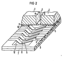
- Fig. 2 ein Ausführungsbeispiel für einen Mehrdüsenscheibkopf,
- Fig. 3 eine Ausgestaltung der Anordnung nach Fig. 2 und
- Fig. 4 eine weitere Ausgestaltung der Anordnung nach
- Fig. 2.
- 1 is an illustration for explaining the driving principle,
- 2 shows an embodiment for a multi-nozzle disc head,
- Fig. 3 shows an embodiment of the arrangement of Fig. 2 and
- Fig. 4 shows a further embodiment of the arrangement
- Fig. 2.
Anhand von Fig. 1 wird zunächst das erfindungsgemäße Ansteuerungsprinzip erläutert. Dazu ist in Fig. 1 ein Magnetsystem vorgesehen, mit dem ein Magnetfeld erzeugt wird, dessen Feldlinien in einem definierten, räumlich begrenzten Bereich eine hohe Dichte aufweisen. Erreicht wird das dadurch, daß die magnetischen Feldlinien B des Magnetfeldes gescheitelt verlaufen. In Fig. 1 besteht das Magnetsystem aus den beiden Magnetkörpern 1 und 2, die derart angeordnet sind, daß gleichnamige Pole, im Beispiel die beiden Nordpole, unter Bildung eines relativ engen Zwischenraums 3 einander gegenüber liegen. Aus diesem Zwischenraum 3 treten die magnetischen Feldlinien B gescheitelt verlaufend nach oben und unten aus.The control principle according to the invention is first explained with reference to FIG. 1. For this purpose, a magnet system is provided in FIG. 1 with which a magnetic field is generated whose field lines have a high density in a defined, spatially limited area. This is achieved in that the magnetic field lines B of the magnetic field are apex. In Fig. 1, the magnet system consists of the two
Ein beidseits des Zwischenraums 3 in einer isolierenden Halterung 4 befestigtes und quer zum Zwischenraum 3 verlaufendes Element, im Beispiel eine Leiterschleife 5, weist zumindest im Bereich der magnetischen Feldlinien B ein pfeilartig abgewinkeltes Mittelteil 6.auf. Das Element 5 ist insofern beweglich, als es zumindest im Bereich des Zwischenraums 3 aus einer Ruhelage ausgelenkt oder abgebogen werden kann. Eine derartige Auslenkung wird beim Durchfluß eines Stromes I durch das Element 5 bewirkt. Geht man von der Annahme aus, daß die magnetischen Feldlinien B des Magnetfeldes in der in Fig. l dargestellten Pfeilrichtung verlaufen, und daß auch der Strom 1 in der ebenfalls durch Pfeile angegebenen Richtung verläuft, so wirkt auf die beiden Schenkel des Mittelteils 6 eine nach oben gerichtete Kraft F ein. Ein Einschalten des Stromes I führt somit zu einer plötzlichen Auslenkung oder Verbiegung des Elements 5 nach oben. Die Richtung der Kraft F und damit auch die Richtung der Bewegung des Elementes 5, zumindest des Mittelteils 6 des Elementes 5, ist von der Richtung des Stromes I und der Richtung der magnetischen Feldlinien B abhängig. Die Größe der Kraft F und damit auch die Größe und die Zeitdauer der Bewegungsänderung des Elements 5 hängt von der Stromstärke, der Magnetfeldstärke und von der Länge des im Magnetfeld verlaufenden und von den magnetischen Feldlinien des Magnetfeldes geschnittenen Teils des Elementes 5 ab.A on both sides of the
In Fig. 2 ist ein Ausführungsbeispiel eines Schreibkopfes für eine Tintenschreibeinrichtung mit mehreren Austrittsöffnungen dargestellt, bei dem die Tröpfchenerzeugung nach diesen Merkmalen erfolgt. Der Schreibkopf nach Fig. 2 ist schichtweise aufgebaut. Er weist eine Düsenplatte 7 mit den Austrittsöffnungen oder Düsenöffnungen 8 auf. Die Düsenplatte 7 bildet zugleich die eine (untere) Wandung einer Tintenkammer 12, deren andere (obere) Wandung durch eine Abdichtplatte 11 gebildet ist. Zwischen der Düsenplatte 7 und der Abdichtplatte 11 sind über die gesamte Länge des Schreibkopfes verlaufend Abstandselemente 9 und 10 angeordnet. Diese bilden die seitlichen Wandungen des Tintenkanals 12. Zugleich dienen sie zur Aufnahme der eigentlichen Antriebselemente 5. Das kann z.B., wie in Fig. 2 gezeigt ist, derart geschehen, daß das untere Abstandselement 9 entsprechende Ausnehmungen besitzt, in die die als Leiterschleife ausgebildeten Antriebselemente 5 beidseitig der Tintenkammer 12 befestigt und gehalten sind. Die Antriebselemente können aber auch als Kontaktflächen bei der Erstellung des Abstandselementes 9 mit gebildet werden. Die Antriebselemente 5 können beispielsweise in Form von schmalen metallischen Streifen ausgebildet sein, die im Bereich der Tintenkammer pfeilartige, im Beispiel nach vorn weisende Abwinkelungen oder Schenkel aufweisen. Dieser Teil des Antriebselementes 5 bildet dann den im vorhergehenden beschriebenen Mittelteil 6. Deren Anordnung ist derart, daß sich das vordere Ende jedes Mittelteils 6 unmittelbar über einer Austrittsöffnung 8 der Düsenplatte 7 befindet.2 shows an exemplary embodiment of a writing head for an ink writing device with a plurality of outlet openings, in which the droplet generation takes place according to these features. 2 is built up in layers. It has a nozzle plate 7 with the outlet openings or
Über der Abdichtplatte 11 ist das Magnetsystem, im Beispiel ein Permanentmagnet, angeordnet. Im relativ schmalen Zwischenraum 3 zwischen den beiden, mit ihren gleichnamigen Polen einander gegenüberstehenden Magnetkörpern 1 und 2, verlaufen die magnetischen Feldlinien B des Magnetfeldes gescheitelt und damit sehr dicht. Sie durchdringen die pfeilartigen, im Beispiel nach vorn weisenden Mittelteile 6 der Antriebselemente 5 in einer solchen Richtung, daß bei einem Stromfluß I von rechts nach links (Pfeilrichtung in Fig. 2) der Mittelteil 6 der Antriebselemente 5 nach unten ausgelenkt oder verbogen wird. Dadurch wird ein kleines Tintenvolumen aus der entsprechenden Austrittsöffnung 8 mit großer Geschwindigkeit nach außen gedrückt und verläßt die Austrittsöffnung in Form eines Tröpfchens. Mit Beedigung des Stromflusses I schwingt der bewegliche Mittelteil 6 des Antriebselementes 5 wieder zurück und sichert durch ein geringes Uberschwingen in die andere Richtung das Nachsaugen von Schreibflüssigkeit.The magnet system, in the example a permanent magnet, is arranged above the sealing plate 11. In the relatively
Die Anordnung ist, wie Fig. 2 zeigt, schichtweise aufgebaut. Da die Anordnung nicht auf eine bestimmte Anzahl von Düsen beschränkt ist, und da sich das Magnetsystem über sämtliche Antriebselemente 5, 6 erstreckt, also sämtlichen Antriebselementen gemeinsam zugeordnet ist, und die gesamte Anordnung aus wenigen und ohne nennenswerten Aufwand herstellbaren und montierbaren Teilen besteht, kann ein derart aufgebauter Schreibkopf die Abmessungen einer gesamten Druckzeile aufweisen. Das ermöglicht mit Vorteil den Einsatz in einer zeilenweise drukkenden Schreibeinrichtung, bei der die Zeichen einer gesamten Scheibzeile linienweise durch einzelne Punkte gebildet werden. Die damit erreichbaren Schreibgeschwindigkeiten liegen deutlich über denen üblicher Tintenmosaikdrucker.As shown in FIG. 2, the arrangement is constructed in layers. Since the arrangement is not limited to a specific number of nozzles, and since the magnet system extends over all drive
Die Düsenplatte 7, die Abstandselemente 9 und 10 und die Abdichtplatte 11 können z.B. aus sogenannten Plenarschichten bestehen. Dabei 'können, was im Rahmen der Erfindung liegt, auch die Antriebselemente 5 als Plenarschichten gebildet werden.The nozzle plate 7, the
Die gesamte Anordnung kann z.B. mit einer Kunststoffummantelung (14 in Fig. 3 und 4) umschlossen sein. Findet zwischen dem auf diese Weise aufgebauten'Schreibkopf und einem Aufzeichnungsträger (15 in Fig. 3 und 4) eine Relativbewegung statt, und werden die Antriebselemente 5 von einer hier nicht dargestellten Ansteuerungsschaltung mit entsprechenden Stromimpulsen angesteuert, so können beliebige Zeichen durch die rasterförmig auf den Aufzeichnungsträger aufgespritzten Tintentröpfchen aufgebaut und dargestellt werden.The entire arrangement can be enclosed, for example, with a plastic casing (14 in FIGS. 3 and 4). If there is a relative movement between the ' write head ' constructed in this way and a record carrier (15 in Fig. 3 and 4), and the
Die Anordnung des Magnetsystems ist nicht auf die in den Fig. 1 und 2 angegebenen Beispiele beschränkt. In Ausgestaltung der Erfindung ist es auch möglich, das Magnetsystem derart anzuordnen, daß ein Magnetkörper auf der Abdichtplatte 11, der andere Magnetkörper außerhalb der Austrittsdüsen 8 und der Düsenplatte 7 gegenüberliegend angeordnet ist. Ein Beispiel dafür zeigt Fig. 3. Auch in diesem Fall verlaufen die magnetischen Feldlinien gescheitelt und schneiden die, in der Tintenkammer 12 verlaufenden Schenkel der Antriebselemente 5, d.h. diese liegen in einem Bereich einer hohen magnetischen Feldliniendichte.The arrangement of the magnet system is not limited to the examples given in FIGS. 1 and 2. In an embodiment of the invention, it is also possible to arrange the magnet system in such a way that one magnet body is arranged on the sealing plate 11, the other magnet body is arranged opposite one another outside the
Gemäß einer weiteren Ausgestaltung kann das Magnetsystem auch aus mehr als zwei Magnetkörpern aufgebaut sein. Ein Ausführungsbeispiel dafür zeigt Fig. 4. In diesem Fall erstrecken sich zwei Magnetkörper 1 und 2 über der Abdichtplatte 11, während ein weitere Magnetkörper 16 der Düsenplatte 7 gegenüberliegend angeordnet ist. Die Magnetkörper 1, 2 und 16 sind derart angeordnet, daß ihre gleichnamigen Pole, im Beispiel die Nordpole N, aufeinander zuweisen.According to a further embodiment, the magnet system can also be constructed from more than two magnetic bodies. An exemplary embodiment of this is shown in FIG. 4. In this case, two
Mit dieser Anordnung wird insofern eine weitere Verbesserung erreicht, als die magnetischen Feldlinien noch ausgeprägter parallel zur Düsenplatte 7 verlaufen und die Konzentration der magnetischen Feldlinien im Bereich der Schenkel der Antriebselemente 5 erhöht ist.With this arrangement, a further improvement is achieved in that the magnetic field lines run even more distinctly parallel to the nozzle plate 7 and the concentration of the magnetic field lines in the region of the legs of the
Im Ausführungsbeispiel nach Fig. 3 und Fig. 4 ist zum Ein- bzw. zum Ausführen des Aufzeichnungsträgers 15 in bzw. aus dem Schreibkopf jeweils eine vorzugsweise schlitzförmige Öffnung 16 vorgesehen.In the exemplary embodiment according to FIGS. 3 and 4, a preferably slot-shaped
Claims (8)
gekennzeichnet durch
marked by
dadurch gekennzeichnet, daß die Antriebselemente (5,6) als Leiterschleifen ausgebildet sind, die beidseitig des Tintenkanals (12) isolierend befestigt sind, und die im Bereich des Tintenkanals (12) ein pfeilartig abgewinkeltes Mittelteil (6) besitzen, dessen vorderes Ende sich unmittelbar über der dem Antriebselement (5) zugeordneten Austrittsöffnung (8) befindet, . und daß das Magnetsystem (1,2) derart ausgestaltet ist, daß im Bereich der Schenkel der Antriebselemente (6). die magnetischen Feldlinien (B) eine hohe Dichte aufweisen.2. Arrangement according to claim 1,
characterized in that the drive elements (5, 6) are designed as conductor loops, which are insulated on both sides of the ink channel (12), and which have an arrow-shaped angled middle part (6) in the area of the ink channel (12), the front end of which is immediately adjacent located above the outlet opening (8) assigned to the drive element (5),. and that the magnet system (1, 2) is designed in such a way that in the region of the legs of the drive elements (6). the magnetic field lines (B) have a high density.
dadurch gekennzeichnet , daß die Antriebselemente (5,6) mit Stromimpulsen (I) ansteuerbar sind, deren Richtung in Abstimmung mit der Richtung der magnetischen Feldlinien (8) des Magnetsystems (1,2) derart ist,
daß die beweglichen Mittelteile (6) der Antriebselemente (5) in Richtung auf die einem Antriebselement (5) zugeordnete Ausstoßöffnung (8) bewegt werden.3. Arrangement according to claim 1 and 2,
characterized in that the drive elements (5, 6) can be controlled with current pulses (I), the direction of which is in coordination with the direction of the magnetic field lines (8) of the magnet system (1, 2),
that the movable middle parts (6) of the drive elements (5) are moved in the direction of the ejection opening (8) assigned to a drive element (5).
dadurch gekennzeichnet , daß das Magnetsystem (1,2) aus mindestens zwei Magnetkörpern (1,2) besteht, die sämtlichen Antriebselementen (5,6) gemeinsam zugeordnet sind,
daß die gleichnamigen Pole (N) der Magnetkörper (1,2) im Bereich der Mittelteile (6) der Antriebselemente (5) aufeinander zuweisen,
und daß die magnetischen Feldlinien (B) im Zwischenraum zwischen den Magnetkörpern (1,2) gescheitelt verlaufen.4. Ano.rdnung according to claim 3,
characterized in that the magnet system (1, 2) consists of at least two magnetic bodies (1, 2), which are assigned to all drive elements (5, 6) together,
that the poles (N) of the same name of the magnetic bodies (1, 2) point towards one another in the region of the central parts (6) of the drive elements (5)
and that the magnetic field lines (B) in the space between the magnetic bodies (1,2) are parted.
dadurch gekennzeichnet , daß der Tintenkanal (12) in Schichtbauweise durch eine Düsenplatte (7) und eine obere Abdichtplatte (11), sowie durch seitliche Abstandselemente (9,10) gebildet ist, zwischen denen die Antriebselemente (5,6) angeordnet sind,
und daß das Magnetsystem (1,2) sich über die gesamte Länge des Tintenkanals (12) erstreckt.5. arrangement according to claims 1 to 4,
characterized in that the ink channel (12) is formed in a layered construction by a nozzle plate (7) and an upper sealing plate (11), and by lateral spacing elements (9, 10), between which the drive elements (5, 6) are arranged,
and that the magnet system (1,2) extends over the entire length of the ink channel (12).
dadurch gekennzeichnet, daß das Magnetsystem aus zwei Magnetkörpern (1,2) besteht, die auf der Abdichtplatte (11) angeordnet sind.6. Arrangement according to claim 5,
characterized in that the magnet system consists of two magnetic bodies (1, 2) which are arranged on the sealing plate (11).
dadurch gekennzeichnet , daß das Magnetsystem aus zwei Magnetkörpern (1,2) besteht,
und daß der eine Magnetkörper (1) auf der Abdichtplatte (11), der andere Magnetkörper (2) außerhalb der Austrittsöffnungen (8) und der Düsenplatte (7) gegenüberliegend angeordnet ist.7. Arrangement according to claim 5,
characterized in that the magnet system consists of two magnet bodies (1, 2),
and that the one magnetic body (1) on the sealing plate (11), the other magnetic body (2) outside of the outlet openings (8) and the nozzle plate (7) is arranged opposite.
dadurch gekennzeichnet , daß das Magnetsystem aus mindestens drei Magnetkörpern (1,2,16) besteht,
daß jeweils zwei Magnetkörper (1,2) auf der Abdichtplatte (11) und mindestens ein weiterer Magnetkörper (16) außerhalb der Austrittsöffnungen (8) und der Düsenplatte (7) gegenüberliegend angeordnet ist.8. Arrangement according to claim 5,
characterized in that the magnet system consists of at least three magnet bodies (1, 2, 16),
that in each case two magnetic bodies (1, 2) on the sealing plate (11) and at least one further magnetic body (16) outside the outlet openings (8) and the nozzle plate (7) are arranged opposite one another.
Applications Claiming Priority (2)
| Application Number | Priority Date | Filing Date | Title |
|---|---|---|---|
| DE3333939 | 1983-09-20 | ||
| DE3333939 | 1983-09-20 |
Publications (1)
| Publication Number | Publication Date |
|---|---|
| EP0135197A1 true EP0135197A1 (en) | 1985-03-27 |
Family
ID=6209577
Family Applications (1)
| Application Number | Title | Priority Date | Filing Date |
|---|---|---|---|
| EP84111071A Withdrawn EP0135197A1 (en) | 1983-09-20 | 1984-09-17 | Droplets generating device for ink-printer units |
Country Status (3)
| Country | Link |
|---|---|
| US (1) | US4544933A (en) |
| EP (1) | EP0135197A1 (en) |
| JP (1) | JPS6090772A (en) |
Cited By (3)
| Publication number | Priority date | Publication date | Assignee | Title |
|---|---|---|---|---|
| DE3529021A1 (en) * | 1985-08-13 | 1987-02-19 | Siemens Ag | Method for manufacturing unilaterally freely mobile metal structures, especially of metal drive elements for an ink-jet print head |
| DE3709455A1 (en) * | 1987-03-23 | 1988-10-06 | Siemens Ag | Arrangement for an electrodynamically operated ink jet print head |
| DE3732044C1 (en) * | 1987-09-23 | 1989-02-09 | Siemens Ag | Electrophotographic printer |
Families Citing this family (31)
| Publication number | Priority date | Publication date | Assignee | Title |
|---|---|---|---|---|
| DE3333980A1 (en) * | 1983-09-20 | 1985-04-04 | Siemens AG, 1000 Berlin und 8000 München | Arrangement for reducing the feedover effects in ink jet printers |
| DE3445720A1 (en) * | 1984-12-14 | 1986-06-19 | Siemens AG, 1000 Berlin und 8000 München | ARRANGEMENT FOR THE EMISSION OF SINGLE DROPLES FROM THE SPLIT OPENINGS OF AN INK WRITING HEAD |
| US6629646B1 (en) * | 1991-04-24 | 2003-10-07 | Aerogen, Inc. | Droplet ejector with oscillating tapered aperture |
| US5938117A (en) | 1991-04-24 | 1999-08-17 | Aerogen, Inc. | Methods and apparatus for dispensing liquids as an atomized spray |
| WO1993001404A1 (en) * | 1991-07-08 | 1993-01-21 | Yehuda Ivri | Ultrasonic fluid ejector |
| US5450115A (en) * | 1994-10-31 | 1995-09-12 | Xerox Corporation | Apparatus for ionographic printing with a focused ion stream |
| US5758637A (en) | 1995-08-31 | 1998-06-02 | Aerogen, Inc. | Liquid dispensing apparatus and methods |
| US6782886B2 (en) | 1995-04-05 | 2004-08-31 | Aerogen, Inc. | Metering pumps for an aerosolizer |
| US6014970A (en) * | 1998-06-11 | 2000-01-18 | Aerogen, Inc. | Methods and apparatus for storing chemical compounds in a portable inhaler |
| US6085740A (en) | 1996-02-21 | 2000-07-11 | Aerogen, Inc. | Liquid dispensing apparatus and methods |
| US6205999B1 (en) | 1995-04-05 | 2001-03-27 | Aerogen, Inc. | Methods and apparatus for storing chemical compounds in a portable inhaler |
| KR100209515B1 (en) * | 1997-02-05 | 1999-07-15 | 윤종용 | Ejection apparatus and method of ink jet printer using magnetic ink |
| US6235177B1 (en) | 1999-09-09 | 2001-05-22 | Aerogen, Inc. | Method for the construction of an aperture plate for dispensing liquid droplets |
| US8336545B2 (en) | 2000-05-05 | 2012-12-25 | Novartis Pharma Ag | Methods and systems for operating an aerosol generator |
| US6948491B2 (en) | 2001-03-20 | 2005-09-27 | Aerogen, Inc. | Convertible fluid feed system with comformable reservoir and methods |
| US7971588B2 (en) | 2000-05-05 | 2011-07-05 | Novartis Ag | Methods and systems for operating an aerosol generator |
| US7100600B2 (en) | 2001-03-20 | 2006-09-05 | Aerogen, Inc. | Fluid filled ampoules and methods for their use in aerosolizers |
| US6543443B1 (en) | 2000-07-12 | 2003-04-08 | Aerogen, Inc. | Methods and devices for nebulizing fluids |
| US6546927B2 (en) | 2001-03-13 | 2003-04-15 | Aerogen, Inc. | Methods and apparatus for controlling piezoelectric vibration |
| US6550472B2 (en) | 2001-03-16 | 2003-04-22 | Aerogen, Inc. | Devices and methods for nebulizing fluids using flow directors |
| US6732944B2 (en) | 2001-05-02 | 2004-05-11 | Aerogen, Inc. | Base isolated nebulizing device and methods |
| US6554201B2 (en) | 2001-05-02 | 2003-04-29 | Aerogen, Inc. | Insert molded aerosol generator and methods |
| US7677467B2 (en) | 2002-01-07 | 2010-03-16 | Novartis Pharma Ag | Methods and devices for aerosolizing medicament |
| MXPA04006629A (en) | 2002-01-07 | 2004-11-10 | Aerogen Inc | Devices and methods for nebulizing fluids for inhalation. |
| WO2003059424A1 (en) | 2002-01-15 | 2003-07-24 | Aerogen, Inc. | Methods and systems for operating an aerosol generator |
| EP1509259B1 (en) | 2002-05-20 | 2016-04-20 | Novartis AG | Apparatus for providing aerosol for medical treatment and methods |
| US8616195B2 (en) | 2003-07-18 | 2013-12-31 | Novartis Ag | Nebuliser for the production of aerosolized medication |
| US7946291B2 (en) | 2004-04-20 | 2011-05-24 | Novartis Ag | Ventilation systems and methods employing aerosol generators |
| UA94711C2 (en) | 2005-05-25 | 2011-06-10 | Аэроджен, Инк. | Vibration systems and methods of making a vibration system, methods of vibrating a plate, aerosol generating system and method of treating a patient |
| US8021014B2 (en) * | 2006-01-10 | 2011-09-20 | Valinge Innovation Ab | Floor light |
| US7997709B2 (en) * | 2006-06-20 | 2011-08-16 | Eastman Kodak Company | Drop on demand print head with fluid stagnation point at nozzle opening |
Citations (3)
| Publication number | Priority date | Publication date | Assignee | Title |
|---|---|---|---|---|
| FR2230879A1 (en) * | 1973-05-21 | 1974-12-20 | Rca Corp | |
| DE2905063A1 (en) * | 1979-02-10 | 1980-08-14 | Olympia Werke Ag | Ink nozzle air intake avoidance system - has vibratory pressure generator shutting bore in membrane in rest position |
| US4336544A (en) * | 1980-08-18 | 1982-06-22 | Hewlett-Packard Company | Method and apparatus for drop-on-demand ink jet printing |
Family Cites Families (3)
| Publication number | Priority date | Publication date | Assignee | Title |
|---|---|---|---|---|
| US3946398A (en) * | 1970-06-29 | 1976-03-23 | Silonics, Inc. | Method and apparatus for recording with writing fluids and drop projection means therefor |
| DE2527647C3 (en) * | 1975-06-20 | 1981-06-25 | Siemens AG, 1000 Berlin und 8000 München | Writing implement that works with liquid droplets |
| US4158847A (en) * | 1975-09-09 | 1979-06-19 | Siemens Aktiengesellschaft | Piezoelectric operated printer head for ink-operated mosaic printer units |
-
1984
- 1984-08-31 US US06/646,146 patent/US4544933A/en not_active Expired - Fee Related
- 1984-09-17 EP EP84111071A patent/EP0135197A1/en not_active Withdrawn
- 1984-09-19 JP JP59194954A patent/JPS6090772A/en active Pending
Patent Citations (3)
| Publication number | Priority date | Publication date | Assignee | Title |
|---|---|---|---|---|
| FR2230879A1 (en) * | 1973-05-21 | 1974-12-20 | Rca Corp | |
| DE2905063A1 (en) * | 1979-02-10 | 1980-08-14 | Olympia Werke Ag | Ink nozzle air intake avoidance system - has vibratory pressure generator shutting bore in membrane in rest position |
| US4336544A (en) * | 1980-08-18 | 1982-06-22 | Hewlett-Packard Company | Method and apparatus for drop-on-demand ink jet printing |
Non-Patent Citations (3)
| Title |
|---|
| IBM TECHNICAL DISCLOSURE BULLETIN, Band 16, Nr. 2, Juli 1973, Seiten 467-468, Armonk, New York, US; F. HOCHBERG u.a.: "Multinozzle line printer using electromagnetic valving" * |
| IBM TECHNICAL DISCLOSURE BULLETIN, Band 16, Nr. 6, November 1973, Seite 1834, Armonk, New York, US; A.H. BATTISON u.a.: "Moving coil ink jet print head" * |
| IBM TECHNICAL DISCLOSURE BULLETIN, Band 18, Nr. 7, Dezember 1975, Seiten 2195-2196, Armonk, New York, US; E. LENNEMANN u.a.: "Mercury controlled ink jet" * |
Cited By (3)
| Publication number | Priority date | Publication date | Assignee | Title |
|---|---|---|---|---|
| DE3529021A1 (en) * | 1985-08-13 | 1987-02-19 | Siemens Ag | Method for manufacturing unilaterally freely mobile metal structures, especially of metal drive elements for an ink-jet print head |
| DE3709455A1 (en) * | 1987-03-23 | 1988-10-06 | Siemens Ag | Arrangement for an electrodynamically operated ink jet print head |
| DE3732044C1 (en) * | 1987-09-23 | 1989-02-09 | Siemens Ag | Electrophotographic printer |
Also Published As
| Publication number | Publication date |
|---|---|
| JPS6090772A (en) | 1985-05-21 |
| US4544933A (en) | 1985-10-01 |
Similar Documents
| Publication | Publication Date | Title |
|---|---|---|
| EP0135197A1 (en) | Droplets generating device for ink-printer units | |
| DE2944005C2 (en) | ||
| DE2945658C2 (en) | ||
| EP0128456B1 (en) | Piezoelectrically actuated writing head | |
| DE2543451C2 (en) | Piezoelectrically operated writing head for ink mosaic writing devices | |
| DE3012720C2 (en) | ||
| DE3202937C2 (en) | Ink jet recording head | |
| DE60111817T2 (en) | INK JET UNIT WITH INCREASED DROP REDUCTION THROUGH ASYMMETRICAL HEATING | |
| DE3245283A1 (en) | Arrangement for expelling liquid droplets | |
| DE3248087A1 (en) | LIQUID JET HEAD | |
| EP0121894B1 (en) | Piezoelectrically operated write head for ink mosaic recording devices | |
| DE3445720A1 (en) | ARRANGEMENT FOR THE EMISSION OF SINGLE DROPLES FROM THE SPLIT OPENINGS OF AN INK WRITING HEAD | |
| DE2344453A1 (en) | INKJET MATRIX PRINTER | |
| EP0150348B1 (en) | Ink jet printing head | |
| DE3804456C2 (en) | ||
| DE3246839A1 (en) | WRITING HEAD FOR A PULSE JET INK RECORDER | |
| DE2812372A1 (en) | INKJET PRINT HEAD | |
| DE69824019T2 (en) | DROPLET PRECIPITATION DEVICE | |
| DE2808275C2 (en) | Inkjet printhead | |
| DE3500985A1 (en) | ARRANGEMENT FOR PRODUCING SINGLE DROPLES IN INK WRITING DEVICES | |
| DE2703320A1 (en) | DROP BEAM RECORDER | |
| DE2554457A1 (en) | INKJET PRINTER | |
| DE3018334C2 (en) | ||
| EP0030382A1 (en) | Printhead for mosaic ink-printing devices | |
| EP0034777A1 (en) | Ink writing apparatus |
Legal Events
| Date | Code | Title | Description |
|---|---|---|---|
| PUAI | Public reference made under article 153(3) epc to a published international application that has entered the european phase |
Free format text: ORIGINAL CODE: 0009012 |
|
| AK | Designated contracting states |
Designated state(s): CH DE FR GB IT LI NL SE |
|
| 17P | Request for examination filed |
Effective date: 19850129 |
|
| STAA | Information on the status of an ep patent application or granted ep patent |
Free format text: STATUS: THE APPLICATION HAS BEEN WITHDRAWN |
|
| 18W | Application withdrawn |
Withdrawal date: 19860402 |
|
| RIN1 | Information on inventor provided before grant (corrected) |
Inventor name: HEINZL, JOACHIM, PROF. DR.-ING. |