EP0133901A2 - Toner replenishment and cartridge package system - Google Patents
Toner replenishment and cartridge package system Download PDFInfo
- Publication number
- EP0133901A2 EP0133901A2 EP84107429A EP84107429A EP0133901A2 EP 0133901 A2 EP0133901 A2 EP 0133901A2 EP 84107429 A EP84107429 A EP 84107429A EP 84107429 A EP84107429 A EP 84107429A EP 0133901 A2 EP0133901 A2 EP 0133901A2
- Authority
- EP
- European Patent Office
- Prior art keywords
- cartridge
- package
- toner
- flap
- overpack
- Prior art date
- Legal status (The legal status is an assumption and is not a legal conclusion. Google has not performed a legal analysis and makes no representation as to the accuracy of the status listed.)
- Granted
Links
Images


Classifications
-
- G—PHYSICS
- G03—PHOTOGRAPHY; CINEMATOGRAPHY; ANALOGOUS TECHNIQUES USING WAVES OTHER THAN OPTICAL WAVES; ELECTROGRAPHY; HOLOGRAPHY
- G03G—ELECTROGRAPHY; ELECTROPHOTOGRAPHY; MAGNETOGRAPHY
- G03G15/00—Apparatus for electrographic processes using a charge pattern
- G03G15/06—Apparatus for electrographic processes using a charge pattern for developing
- G03G15/08—Apparatus for electrographic processes using a charge pattern for developing using a solid developer, e.g. powder developer
- G03G15/0822—Arrangements for preparing, mixing, supplying or dispensing developer
- G03G15/0865—Arrangements for supplying new developer
- G03G15/0875—Arrangements for supplying new developer cartridges having a box like shape
-
- G—PHYSICS
- G03—PHOTOGRAPHY; CINEMATOGRAPHY; ANALOGOUS TECHNIQUES USING WAVES OTHER THAN OPTICAL WAVES; ELECTROGRAPHY; HOLOGRAPHY
- G03G—ELECTROGRAPHY; ELECTROPHOTOGRAPHY; MAGNETOGRAPHY
- G03G15/00—Apparatus for electrographic processes using a charge pattern
- G03G15/06—Apparatus for electrographic processes using a charge pattern for developing
- G03G15/08—Apparatus for electrographic processes using a charge pattern for developing using a solid developer, e.g. powder developer
- G03G15/0822—Arrangements for preparing, mixing, supplying or dispensing developer
- G03G15/0848—Arrangements for testing or measuring developer properties or quality, e.g. charge, size, flowability
- G03G15/0849—Detection or control means for the developer concentration
- G03G15/0855—Detection or control means for the developer concentration the concentration being measured by optical means
-
- G—PHYSICS
- G03—PHOTOGRAPHY; CINEMATOGRAPHY; ANALOGOUS TECHNIQUES USING WAVES OTHER THAN OPTICAL WAVES; ELECTROGRAPHY; HOLOGRAPHY
- G03G—ELECTROGRAPHY; ELECTROPHOTOGRAPHY; MAGNETOGRAPHY
- G03G15/00—Apparatus for electrographic processes using a charge pattern
- G03G15/06—Apparatus for electrographic processes using a charge pattern for developing
- G03G15/08—Apparatus for electrographic processes using a charge pattern for developing using a solid developer, e.g. powder developer
- G03G15/0822—Arrangements for preparing, mixing, supplying or dispensing developer
- G03G15/0865—Arrangements for supplying new developer
-
- G—PHYSICS
- G03—PHOTOGRAPHY; CINEMATOGRAPHY; ANALOGOUS TECHNIQUES USING WAVES OTHER THAN OPTICAL WAVES; ELECTROGRAPHY; HOLOGRAPHY
- G03G—ELECTROGRAPHY; ELECTROPHOTOGRAPHY; MAGNETOGRAPHY
- G03G15/00—Apparatus for electrographic processes using a charge pattern
- G03G15/06—Apparatus for electrographic processes using a charge pattern for developing
- G03G15/08—Apparatus for electrographic processes using a charge pattern for developing using a solid developer, e.g. powder developer
- G03G15/0822—Arrangements for preparing, mixing, supplying or dispensing developer
- G03G15/0877—Arrangements for metering and dispensing developer from a developer cartridge into the development unit
- G03G15/0881—Sealing of developer cartridges
- G03G15/0884—Sealing of developer cartridges by a sealing film to be ruptured or cut
-
- Y—GENERAL TAGGING OF NEW TECHNOLOGICAL DEVELOPMENTS; GENERAL TAGGING OF CROSS-SECTIONAL TECHNOLOGIES SPANNING OVER SEVERAL SECTIONS OF THE IPC; TECHNICAL SUBJECTS COVERED BY FORMER USPC CROSS-REFERENCE ART COLLECTIONS [XRACs] AND DIGESTS
- Y10—TECHNICAL SUBJECTS COVERED BY FORMER USPC
- Y10S—TECHNICAL SUBJECTS COVERED BY FORMER USPC CROSS-REFERENCE ART COLLECTIONS [XRACs] AND DIGESTS
- Y10S222/00—Dispensing
- Y10S222/01—Xerography
Definitions
- the present invention relates to the field of electrophotographic reproduction, and to constructions and arrangements for replenishing xerographic toner to the developer station of such reproduction devices.
- the toner cartridge disclosed in this application is of the construction and arrangement disclosed and claimed in copending European patent application (B0983015), incorporated herein by reference. While this toner cartridge is of exemplary utility in the present invention, the present invention is not to be limited by this specific construction and arrangement.
- the aforesaid copending application describes a cartridge of this type.
- Other examples are U. S. Patents 3,999,654 and 4,062,385.
- practice of the present invention involves use of a double-function storage and shipment box or package in which a toner cartridge is contained or housed as the toner awaits use in an electrophotographic device such as a copier or a printer. More specifically, this double use involves use of the box to facilitate clean-loading of the toner cartridge unto or into the reproduction device; i.e., the box functions to catch toner which may escape from the device as the cartridge is opened to dump its toner content into the developer unit or station of the reproduction device.
- the IBM 3800 laser printer is used as an example.
- the reproduction device's developer station be provided with a slot 27 (or an equivalent flap-receiver) which will receive tuck-flap 22 of the present invention.
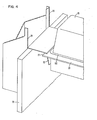
- the reproduction device include a means to aid in supporting and positioning the opened box of the present invention, much as the 3800's outer cover 30 which is shown in FIG. 4.
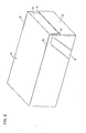
- the toner-cartridge-containing box aforesaid is of a general parallelepiped shape, as seen in FIG's. 1, 2 and 6. It is preferably formed of corrugated paper board of 275 pounds bursting strength, B flute, single-wall construction. Cartridge 26, which is contained within the box, holds about eight pounds of xerographic toner. The details of construction of this cartridge are contained in the aforesaid copending application. These details are not critical to the present invention.
- the box is of conventional construction, with the exception of the end of the box which is best seen in FIG's. 1 and 6.
- This end of the box includes a removable end portion 10 which includes end flaps 60, 61 and 62.
- End 10 is removed merely by removing tabs 20 and 21.
- tabs 20 and 21 terminate at through-cuts 202. Removal of these tabs is facilitated by the fact that these tabs are connected to the box only by virtue of zipper perforations, shown in dotted lines in the figures. An alternative construction of tabs 20 and 21 is later described.
- the top of the box includes a through-cut area 201 and a tab 32 which can be manually pushed inward, as shown, to allow finger access to the underside of portion 33 of zipper tab 21. Once tab 21 has been removed, tab 20 is available for convenient removal.
- the toner cartridge is provided with a recess 31 which accommodates inward movement of tab 32.
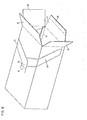
- box end 10 can now be removed is apparent from a consideration of FIG's. 1 and 6.
- the box is sealed by first folding side flaps 60 and 61 inward from their FIG. 6 position. Tuck-flap 22 is then folded inward. It is important to note that the upper end 63 of this tuck-flap does not penetrate an excessive distance under top flap 62 (see FIG. 1).
- top flap 62 is folded and secured (i.e., glued) to only the overlapped portions of side flaps 60 and 61. Glue is not applied to portion 63 of tuck-flap 22.
- end 10 and 21 are removed, as aforesaid, end 10, including its flaps 60, 61 and 62, are separated from the box and the end can be removed and discarded.
- the reproduction device's toner replenisher 29 includes a toner compartment 100 which is adapted to hold somewhat more than the eight-pound capacity of cartridge 26.
- toner is metered from compartment 100 to the reproduction device's magnetic brush developer (not shown) as toner is gradually used up in the production of prints.
- the upward facing opening of compartment 100 is of a complementary shape to the bottom shaped opening of toner cartridge 26.
- This upward shaped opening includes a continuous flange 28 which surrounds the opening, and which includes means (not shown) for guiding, sealing and clamping the complementary flange 102 which is formed about the cartridge's bottom disposed toner dump opening.
- Flange 28 includes a slot 27 which is constructed and arranged to receive flap 22, with a somewhat close fit, so as to effectively provide a means for mounting the box onto the toner replenisher, as shown. In this position, the box is manually held in a horizontal position, as cartridge 26 is slid onto replenisher. In the case of a 3800-like construction, an exterior cabinet member 30 is conveniently available to aid in the horizontal positioning of the box, as shown in FIG. 3. Notch 31 which is formed in the top of cartridge 26 (FIG. 5) provides a convenient means on which to manually push, in order to move the cartridge from the box to the replenisher.
- the box can be released from manual support, and the cartridge can be opened, to dump its content to compartment 100.
- the exposed end of the cartridge i.e., the end which is not exposed to view in FIG. 3 contains the pull tab of a traveling fold seal strip which is peelably sealed to cartridge flange 102 (reference may be had to the aforesaid copending application for a detailed description of this seal strip).
- a further unique utility of the present invention is that the box remains in position, mounted to slot 27, during the opening of cartridge 26. As such the box is in position to receive the cartridge's seal, whatever may be its form, and to also receive any toner which may be transported out of the cartridge on the seal. Thus, clean loading of toner into the replenisher is insured.
- the box hangs from slot 27 during the procedure of opening the toner cartridge.
- This hanging attitude is better facilitated by the provision of two zipper perforations 23 and 24 located on the bottom surface 25 of the box. Manual separation of these perforations allows the box to better hang relative developer flange 28; and in the case of the 3800-like construction, zipper perforations 23 and 24 provide a unique utility relative cabinet member 30, as seen in FIG. 4.
- the toner cartridge is left in position on the top of the replenisher, much in the nature of a cover. In others, the cartridge is immediately removed, after toner is dumped to the replenisher, and a separate cover is put in its place.
- the box In the case of the former type, the box is stored and later remounted to slot 27, as aforesaid, in order to receive the empty cartridge 26. The box is then removed, and discarded, as a box containing a full cartridge is immediately mounted on slot 27. In the case of the latter type device, the box is left in position to immediately receive the now-empty cartridge - again facilitating cleanliness of the entire operation.
- FIG. 4 shows that a portion of the box associated with zipper perforations 23 and 24 sticks up above the plane of replenisher flange 28.
- an alternative construction moves the zipper perforations on the sides of the box, such that tabs 20 and 21 terminate at the ends of zipper perforations 24 and 23, respectively.
- Reference number 200 has been added to FIG.
Abstract
Description
- The present invention relates to the field of electrophotographic reproduction, and to constructions and arrangements for replenishing xerographic toner to the developer station of such reproduction devices.
- The toner cartridge disclosed in this application is of the construction and arrangement disclosed and claimed in copending European patent application (B0983015), incorporated herein by reference. While this toner cartridge is of exemplary utility in the present invention, the present invention is not to be limited by this specific construction and arrangement.
- The problem of replenishing toner to a xerographic developer station, in a convenient, clean and safe manner, while at the same time providing physical protection to the toner cartridge during storage, shipment, etc., has been worked on for many years by those skilled in this art.
- A particularly good way to seal the cartridge and, at the same time, provide convenient and somewhat clean dumping of the toner to the developer station, involves the use of a traveling-fold seal which is glued to the bottom-disposed dump-opening of a box-like cartridge. The aforesaid copending application describes a cartridge of this type. Other examples are U. S. Patents 3,999,654 and 4,062,385.
- Prior to the present invention, all such cartridges were placed in a conventional, strong, corrugated paperboard box. This box was opened at the site of the device whose toner is to be replenished, the toner cartridge was removed, the now-empty box was set aside, and the cartridge was mounted on the reproduction device. The traveling-fold seal was then removed.
- The features and advantages of the invention will be apparent from the following more particular description of preferred embodiments of the invention, as illustrated in the accompanying drawing.
-
- FIG. 1 shows the toner cartridge's protective outer package, as viewed from the top, and from the end (10) which is removable by operation of two zipper-perforated removable tabs (20, 21);
- FIG. 2 is a view of the same end of the outer package, but shows the underside of the package, and the way in which the package's tuck-flap (22) is attached to the bottom surface (25) of the package by a pair of zipper perforations (23, 24);
- FIG. 3 is a view showing the end (10) of the outer package removed, to expose a full toner cartridge (26). The package's tuck-flap (22) has been inserted into a slot (27) in the flange (28) of the reproduction device's toner replenisher unit (29). In this position, the cartridge (26) is aligned with the top of the replenisher unit, and as the package is supported by hand, while an exterior cabinet portion (30) of the reproduction device may help support and position the package;
- FIG. 4 shows the toner cartridge in position on the reproduction device's toner replenisher. The tuck-flap's two zipper perforations (23, 24) have been severed so that the package's now-empty cavity faces upward, ready to receive the cartridge's traveling-fold seal, and any toner which may be brought out of the cartridge on the face of the seal;
- FIG. 5 shows a recess (31) formed in the top of the toner cartridge, which recess enables a top portion (32) of the package to be manually pushed inward, to provide finger-access to the end (33) of one (21) of the zipper-perforated removable tabs; and
- FIG. 6 is a view like FIG. 1, showing the empty outer package, and particularly how the package is closed by first folding the side flaps (60 and 61), then folding the tuck-flap (22) without gluing, and lastly folding and gluing the top flap (62) to only the side flaps.
- Practice of the present invention involves use of a double-function storage and shipment box or package in which a toner cartridge is contained or housed as the toner awaits use in an electrophotographic device such as a copier or a printer. More specifically, this double use involves use of the box to facilitate clean-loading of the toner cartridge unto or into the reproduction device; i.e., the box functions to catch toner which may escape from the device as the cartridge is opened to dump its toner content into the developer unit or station of the reproduction device.
- In the following description, the IBM 3800 laser printer is used as an example. However, all that is necessary in order to practice the present invention is that the reproduction device's developer station be provided with a slot 27 (or an equivalent flap-receiver) which will receive tuck-
flap 22 of the present invention. In addition, it is desirable (but not essential) that the reproduction device include a means to aid in supporting and positioning the opened box of the present invention, much as the 3800'souter cover 30 which is shown in FIG. 4. - The toner-cartridge-containing box aforesaid is of a general parallelepiped shape, as seen in FIG's. 1, 2 and 6. It is preferably formed of corrugated paper board of 275 pounds bursting strength, B flute, single-wall construction. Cartridge 26, which is contained within the box, holds about eight pounds of xerographic toner. The details of construction of this cartridge are contained in the aforesaid copending application. These details are not critical to the present invention.
- The box is of conventional construction, with the exception of the end of the box which is best seen in FIG's. 1 and 6. This end of the box includes a
removable end portion 10 which includesend flaps End 10 is removed merely by removingtabs tabs cuts 202. Removal of these tabs is facilitated by the fact that these tabs are connected to the box only by virtue of zipper perforations, shown in dotted lines in the figures. An alternative construction oftabs - As is best seen in FIG. 5, the top of the box includes a through-
cut area 201 and atab 32 which can be manually pushed inward, as shown, to allow finger access to the underside ofportion 33 ofzipper tab 21. Oncetab 21 has been removed,tab 20 is available for convenient removal. Ideally, the toner cartridge is provided with arecess 31 which accommodates inward movement oftab 32. - The fact that
box end 10 can now be removed is apparent from a consideration of FIG's. 1 and 6. Aftercartridge 26 is inserted in the box, at the location of toner manufacture, the box is sealed by first foldingside flaps flap 22 is then folded inward. It is important to note that theupper end 63 of this tuck-flap does not penetrate an excessive distance under top flap 62 (see FIG. 1). Lastly,top flap 62 is folded and secured (i.e., glued) to only the overlapped portions ofside flaps portion 63 of tuck-flap 22. Thus, oncezipper flaps end 10, including itsflaps - The unique utility of tuck-
flap 22 is evident from FIG. 4. There it is shown that the reproduction device'stoner replenisher 29 includes atoner compartment 100 which is adapted to hold somewhat more than the eight-pound capacity ofcartridge 26. As is known to those of skill in the art, toner is metered fromcompartment 100 to the reproduction device's magnetic brush developer (not shown) as toner is gradually used up in the production of prints. The upward facing opening ofcompartment 100 is of a complementary shape to the bottom shaped opening oftoner cartridge 26. This upward shaped opening includes acontinuous flange 28 which surrounds the opening, and which includes means (not shown) for guiding, sealing and clamping thecomplementary flange 102 which is formed about the cartridge's bottom disposed toner dump opening.Flange 28 includes aslot 27 which is constructed and arranged to receiveflap 22, with a somewhat close fit, so as to effectively provide a means for mounting the box onto the toner replenisher, as shown. In this position, the box is manually held in a horizontal position, ascartridge 26 is slid onto replenisher. In the case of a 3800-like construction, anexterior cabinet member 30 is conveniently available to aid in the horizontal positioning of the box, as shown in FIG. 3.Notch 31 which is formed in the top of cartridge 26 (FIG. 5) provides a convenient means on which to manually push, in order to move the cartridge from the box to the replenisher. - Now that the cartridge is in position on the replenisher, the box can be released from manual support, and the cartridge can be opened, to dump its content to
compartment 100. The exposed end of the cartridge (i.e., the end which is not exposed to view in FIG. 3) contains the pull tab of a traveling fold seal strip which is peelably sealed to cartridge flange 102 (reference may be had to the aforesaid copending application for a detailed description of this seal strip). A further unique utility of the present invention is that the box remains in position, mounted toslot 27, during the opening ofcartridge 26. As such the box is in position to receive the cartridge's seal, whatever may be its form, and to also receive any toner which may be transported out of the cartridge on the seal. Thus, clean loading of toner into the replenisher is insured. - As previously mentioned, the box hangs from
slot 27 during the procedure of opening the toner cartridge. This hanging attitude is better facilitated by the provision of twozipper perforations bottom surface 25 of the box. Manual separation of these perforations allows the box to better hangrelative developer flange 28; and in the case of the 3800-like construction,zipper perforations relative cabinet member 30, as seen in FIG. 4. - In some xerographic devices, the toner cartridge is left in position on the top of the replenisher, much in the nature of a cover. In others, the cartridge is immediately removed, after toner is dumped to the replenisher, and a separate cover is put in its place. In the case of the former type, the box is stored and later remounted to slot 27, as aforesaid, in order to receive the
empty cartridge 26. The box is then removed, and discarded, as a box containing a full cartridge is immediately mounted onslot 27. In the case of the latter type device, the box is left in position to immediately receive the now-empty cartridge - again facilitating cleanliness of the entire operation. - FIG. 4 shows that a portion of the box associated with
zipper perforations replenisher flange 28. Depending upon the type of clamp which is used to hold and sealcartridge flange 102 to replenisher flange 28 (and the details of this clamp are not critical to the present invention), it is possible, within the teachings of the present invention, to modify the location of zipper perforatedtabs tabs zipper perforations Reference number 200 has been added to FIG. 1 to identify the terminating end oftab 20 for such an alternate construction of the present invention. With this construction and arrangement, theremovable portion 10 of the box now must be separated from the remainder of the box, after removal oftabs zipper perforations flange 28, when this alternate construction is in the position of FIG. 4. - While the invention has been particularly shown and described with reference to preferred embodiments thereof, it will be understood by those skilled in the art that various changes in form and details may be made therein without departing from the spirit and scope of the invention.
Claims (10)
Applications Claiming Priority (2)
| Application Number | Priority Date | Filing Date | Title |
|---|---|---|---|
| US06/514,996 US4502514A (en) | 1983-07-18 | 1983-07-18 | Toner cartridge and method of replenishing toner to a xerographic device |
| US514996 | 1983-07-18 |
Publications (3)
| Publication Number | Publication Date |
|---|---|
| EP0133901A2 true EP0133901A2 (en) | 1985-03-13 |
| EP0133901A3 EP0133901A3 (en) | 1985-04-17 |
| EP0133901B1 EP0133901B1 (en) | 1986-12-17 |
Family
ID=24049566
Family Applications (1)
| Application Number | Title | Priority Date | Filing Date |
|---|---|---|---|
| EP84107429A Expired EP0133901B1 (en) | 1983-07-18 | 1984-06-28 | Toner replenishment and cartridge package system |
Country Status (3)
| Country | Link |
|---|---|
| US (1) | US4502514A (en) |
| EP (1) | EP0133901B1 (en) |
| DE (1) | DE3461735D1 (en) |
Cited By (2)
| Publication number | Priority date | Publication date | Assignee | Title |
|---|---|---|---|---|
| GB2300853A (en) * | 1995-05-18 | 1996-11-20 | United Biscuits Ltd | Packaging |
| DE202010013707U1 (en) * | 2010-09-28 | 2011-11-02 | Mayr-Melnhof Karton Ag | Folding box and blank for this |
Families Citing this family (15)
| Publication number | Priority date | Publication date | Assignee | Title |
|---|---|---|---|---|
| DE8717167U1 (en) * | 1986-10-17 | 1988-05-05 | Fuji Photo Film Co., Ltd., Minami-Ashigara, Kanagawa, Jp | |
| FR2666310B1 (en) * | 1990-09-05 | 1993-08-13 | Novembal Sa | TAMPER-FREE PACKAGE HAVING AN INTERNAL ENVELOPE AND AN OUTER ENVELOPE AND METHOD FOR MANUFACTURING THE SAME. |
| JPH04263273A (en) * | 1991-02-17 | 1992-09-18 | Ricoh Co Ltd | Image forming device |
| US5305881A (en) * | 1991-12-10 | 1994-04-26 | Lever Brothers Company, Division Of Conopco, Inc. | Dispenser for fabric softener sheets |
| US5310057A (en) * | 1991-12-10 | 1994-05-10 | Lever Brothers Company, Division Of Conopco, Inc. | Fabric softener sheet dispenser |
| US5264901A (en) * | 1992-12-28 | 1993-11-23 | Future Communications Corporation | Toner cartridge seal |
| EP0706947A1 (en) * | 1994-10-13 | 1996-04-17 | The Procter & Gamble Company | Display containers |
| US5803348A (en) * | 1994-10-13 | 1998-09-08 | The Procter & Gamble Company | Display containers |
| JP4157681B2 (en) * | 2000-02-14 | 2008-10-01 | 株式会社リコー | Toner storage container |
| US7024835B2 (en) * | 2001-10-24 | 2006-04-11 | Hewlett-Packard Development Company, L.P. | Apparatus and method for opening sealed containers |
| US20060006216A1 (en) * | 2004-07-07 | 2006-01-12 | Moll Theresa A | Envelope container and dispenser |
| WO2007149441A2 (en) * | 2006-06-19 | 2007-12-27 | William Volz | Easily disposable modular container for pizza and the like |
| US8393529B2 (en) * | 2007-02-20 | 2013-03-12 | William Gerard Volz | EZ-fold modular pizza box |
| US20140191022A1 (en) * | 2013-01-04 | 2014-07-10 | William Gerard Volz | Method of Using Modular Pizza Box |
| US9002235B2 (en) * | 2013-02-27 | 2015-04-07 | Hewlett-Packard Development Company, L.P. | Toner cartridge packaging |
Citations (10)
| Publication number | Priority date | Publication date | Assignee | Title |
|---|---|---|---|---|
| GB1272273A (en) * | 1968-05-01 | 1972-04-26 | Eastman Kodak Co | Containers and dispensers for electrophotographic toner |
| GB1272272A (en) * | 1968-05-01 | 1972-04-26 | Eastman Kodak Co | Means for handling a toner container in an electrographic machine |
| US3669345A (en) * | 1971-01-07 | 1972-06-13 | Riegel Paper Corp | Reclosable composite package |
| US3999654A (en) * | 1972-12-13 | 1976-12-28 | Van Dyke Research Corporation | Toner cartridge |
| DE1922208B2 (en) * | 1968-05-01 | 1977-08-25 | Eastman Kodak Co, Rochester, N.Y. (V.St.A.) | Container and supply mechanism for the dye powder - in a dry electrostatic printer |
| US4062385A (en) * | 1975-03-14 | 1977-12-13 | Eastman Kodak Company | Toner handling apparatus |
| US4113100A (en) * | 1977-01-27 | 1978-09-12 | Stone Container Corporation | Display carton |
| DE1572362B2 (en) * | 1966-04-29 | 1979-03-08 | Rank Xerox Ltd., London | Image powder refill pack for electrophotographic copying machines |
| EP0070731A2 (en) * | 1981-07-22 | 1983-01-26 | Konica Corporation | Method of supplying a fine-particle powder |
| DE3140389A1 (en) * | 1981-10-10 | 1983-06-01 | S.A. Camp, Fábrica de Jabones, Granollers, Barcelona | Folding box |
Family Cites Families (1)
| Publication number | Priority date | Publication date | Assignee | Title |
|---|---|---|---|---|
| US3326364A (en) * | 1965-03-22 | 1967-06-20 | Reynolds Metals Co | Container construction and parts therefor or the like |
-
1983
- 1983-07-18 US US06/514,996 patent/US4502514A/en not_active Expired - Fee Related
-
1984
- 1984-06-28 DE DE8484107429T patent/DE3461735D1/en not_active Expired
- 1984-06-28 EP EP84107429A patent/EP0133901B1/en not_active Expired
Patent Citations (10)
| Publication number | Priority date | Publication date | Assignee | Title |
|---|---|---|---|---|
| DE1572362B2 (en) * | 1966-04-29 | 1979-03-08 | Rank Xerox Ltd., London | Image powder refill pack for electrophotographic copying machines |
| GB1272273A (en) * | 1968-05-01 | 1972-04-26 | Eastman Kodak Co | Containers and dispensers for electrophotographic toner |
| GB1272272A (en) * | 1968-05-01 | 1972-04-26 | Eastman Kodak Co | Means for handling a toner container in an electrographic machine |
| DE1922208B2 (en) * | 1968-05-01 | 1977-08-25 | Eastman Kodak Co, Rochester, N.Y. (V.St.A.) | Container and supply mechanism for the dye powder - in a dry electrostatic printer |
| US3669345A (en) * | 1971-01-07 | 1972-06-13 | Riegel Paper Corp | Reclosable composite package |
| US3999654A (en) * | 1972-12-13 | 1976-12-28 | Van Dyke Research Corporation | Toner cartridge |
| US4062385A (en) * | 1975-03-14 | 1977-12-13 | Eastman Kodak Company | Toner handling apparatus |
| US4113100A (en) * | 1977-01-27 | 1978-09-12 | Stone Container Corporation | Display carton |
| EP0070731A2 (en) * | 1981-07-22 | 1983-01-26 | Konica Corporation | Method of supplying a fine-particle powder |
| DE3140389A1 (en) * | 1981-10-10 | 1983-06-01 | S.A. Camp, Fábrica de Jabones, Granollers, Barcelona | Folding box |
Cited By (2)
| Publication number | Priority date | Publication date | Assignee | Title |
|---|---|---|---|---|
| GB2300853A (en) * | 1995-05-18 | 1996-11-20 | United Biscuits Ltd | Packaging |
| DE202010013707U1 (en) * | 2010-09-28 | 2011-11-02 | Mayr-Melnhof Karton Ag | Folding box and blank for this |
Also Published As
| Publication number | Publication date |
|---|---|
| EP0133901A3 (en) | 1985-04-17 |
| EP0133901B1 (en) | 1986-12-17 |
| DE3461735D1 (en) | 1987-01-29 |
| US4502514A (en) | 1985-03-05 |
Similar Documents
| Publication | Publication Date | Title |
|---|---|---|
| US4502514A (en) | Toner cartridge and method of replenishing toner to a xerographic device | |
| US5682986A (en) | Cigarette package assembly having a package and a sleeve for spent cigarettes | |
| KR100233329B1 (en) | Cigarette package | |
| US5301804A (en) | Package, especially soft-cup pack for cigarettes | |
| JP2635506B2 (en) | Pack with hinge lid for cigarette | |
| US3710977A (en) | Container for sheets of light-sensitive material | |
| JPH0815910B2 (en) | Cigarette pack | |
| US5918734A (en) | Cigarette packaging with integral lighter receptacle | |
| US5239805A (en) | Method of packing a developer cartridge | |
| US5437407A (en) | Detergent packing paper box | |
| EP0120281B1 (en) | Developer mix shipping container and method for renewing developer mix in a xerographic station | |
| US2112816A (en) | Film package | |
| US5649411A (en) | Method for daylight loading a photographic light-sensitive material | |
| US3761012A (en) | Cartons | |
| JPS62245248A (en) | Light shielding tearable packing cover for wrapping laminated sheet film | |
| US5251755A (en) | Package having a leader secured over a pouch | |
| JPS63187272A (en) | Toner replenishing device for developing device | |
| EP0406816A2 (en) | Packaging carton | |
| JP3071850B2 (en) | Container device | |
| US5199569A (en) | Package for sheets of X-ray film | |
| US2529288A (en) | Container for carbon paper and similar sheet material | |
| US4085884A (en) | Paper supply box | |
| US2335107A (en) | Film package | |
| KR102622821B1 (en) | Packaging box its strap automatically come out | |
| US3033361A (en) | Safety coverlock for book match packages and the like |
Legal Events
| Date | Code | Title | Description |
|---|---|---|---|
| PUAI | Public reference made under article 153(3) epc to a published international application that has entered the european phase |
Free format text: ORIGINAL CODE: 0009012 |
|
| PUAL | Search report despatched |
Free format text: ORIGINAL CODE: 0009013 |
|
| 17P | Request for examination filed |
Effective date: 19841123 |
|
| AK | Designated contracting states |
Designated state(s): DE FR GB |
|
| AK | Designated contracting states |
Designated state(s): DE FR GB |
|
| GRAA | (expected) grant |
Free format text: ORIGINAL CODE: 0009210 |
|
| AK | Designated contracting states |
Kind code of ref document: B1 Designated state(s): DE FR GB |
|
| REF | Corresponds to: |
Ref document number: 3461735 Country of ref document: DE Date of ref document: 19870129 |
|
| ET | Fr: translation filed | ||
| PLBE | No opposition filed within time limit |
Free format text: ORIGINAL CODE: 0009261 |
|
| STAA | Information on the status of an ep patent application or granted ep patent |
Free format text: STATUS: NO OPPOSITION FILED WITHIN TIME LIMIT |
|
| 26N | No opposition filed | ||
| REG | Reference to a national code |
Ref country code: FR Ref legal event code: GC |
|
| REG | Reference to a national code |
Ref country code: GB Ref legal event code: 732 |
|
| REG | Reference to a national code |
Ref country code: FR Ref legal event code: TP |
|
| PGFP | Annual fee paid to national office [announced via postgrant information from national office to epo] |
Ref country code: FR Payment date: 19920515 Year of fee payment: 9 Ref country code: DE Payment date: 19920515 Year of fee payment: 9 |
|
| PGFP | Annual fee paid to national office [announced via postgrant information from national office to epo] |
Ref country code: GB Payment date: 19920529 Year of fee payment: 9 |
|
| PG25 | Lapsed in a contracting state [announced via postgrant information from national office to epo] |
Ref country code: GB Effective date: 19930628 |
|
| GBPC | Gb: european patent ceased through non-payment of renewal fee |
Effective date: 19930628 |
|
| PG25 | Lapsed in a contracting state [announced via postgrant information from national office to epo] |
Ref country code: FR Effective date: 19940228 |
|
| PG25 | Lapsed in a contracting state [announced via postgrant information from national office to epo] |
Ref country code: DE Effective date: 19940301 |
|
| REG | Reference to a national code |
Ref country code: FR Ref legal event code: ST |