EP0133171B1 - Chain net - Google Patents
Chain net Download PDFInfo
- Publication number
- EP0133171B1 EP0133171B1 EP19840850213 EP84850213A EP0133171B1 EP 0133171 B1 EP0133171 B1 EP 0133171B1 EP 19840850213 EP19840850213 EP 19840850213 EP 84850213 A EP84850213 A EP 84850213A EP 0133171 B1 EP0133171 B1 EP 0133171B1
- Authority
- EP
- European Patent Office
- Prior art keywords
- warp
- links
- strands
- weft
- net
- Prior art date
- Legal status (The legal status is an assumption and is not a legal conclusion. Google has not performed a legal analysis and makes no representation as to the accuracy of the status listed.)
- Expired - Lifetime
Links
Images


Classifications
-
- F—MECHANICAL ENGINEERING; LIGHTING; HEATING; WEAPONS; BLASTING
- F16—ENGINEERING ELEMENTS AND UNITS; GENERAL MEASURES FOR PRODUCING AND MAINTAINING EFFECTIVE FUNCTIONING OF MACHINES OR INSTALLATIONS; THERMAL INSULATION IN GENERAL
- F16G—BELTS, CABLES, OR ROPES, PREDOMINANTLY USED FOR DRIVING PURPOSES; CHAINS; FITTINGS PREDOMINANTLY USED THEREFOR
- F16G15/00—Chain couplings, Shackles; Chain joints; Chain links; Chain bushes
- F16G15/02—Chain couplings, Shackles; Chain joints; Chain links; Chain bushes for fastening more or less permanently
-
- B—PERFORMING OPERATIONS; TRANSPORTING
- B60—VEHICLES IN GENERAL
- B60C—VEHICLE TYRES; TYRE INFLATION; TYRE CHANGING; CONNECTING VALVES TO INFLATABLE ELASTIC BODIES IN GENERAL; DEVICES OR ARRANGEMENTS RELATED TO TYRES
- B60C27/00—Non-skid devices temporarily attachable to resilient tyres or resiliently-tyred wheels
- B60C27/06—Non-skid devices temporarily attachable to resilient tyres or resiliently-tyred wheels extending over the complete circumference of the tread, e.g. made of chains or cables
-
- Y—GENERAL TAGGING OF NEW TECHNOLOGICAL DEVELOPMENTS; GENERAL TAGGING OF CROSS-SECTIONAL TECHNOLOGIES SPANNING OVER SEVERAL SECTIONS OF THE IPC; TECHNICAL SUBJECTS COVERED BY FORMER USPC CROSS-REFERENCE ART COLLECTIONS [XRACs] AND DIGESTS
- Y10—TECHNICAL SUBJECTS COVERED BY FORMER USPC
- Y10T—TECHNICAL SUBJECTS COVERED BY FORMER US CLASSIFICATION
- Y10T29/00—Metal working
- Y10T29/49—Method of mechanical manufacture
- Y10T29/49826—Assembling or joining
- Y10T29/4984—Retaining clearance for motion between assembled parts
- Y10T29/49845—Retaining clearance for motion between assembled parts by deforming interlock
-
- Y—GENERAL TAGGING OF NEW TECHNOLOGICAL DEVELOPMENTS; GENERAL TAGGING OF CROSS-SECTIONAL TECHNOLOGIES SPANNING OVER SEVERAL SECTIONS OF THE IPC; TECHNICAL SUBJECTS COVERED BY FORMER USPC CROSS-REFERENCE ART COLLECTIONS [XRACs] AND DIGESTS
- Y10—TECHNICAL SUBJECTS COVERED BY FORMER USPC
- Y10T—TECHNICAL SUBJECTS COVERED BY FORMER US CLASSIFICATION
- Y10T29/00—Metal working
- Y10T29/49—Method of mechanical manufacture
- Y10T29/49826—Assembling or joining
- Y10T29/49863—Assembling or joining with prestressing of part
- Y10T29/4987—Elastic joining of parts
-
- Y—GENERAL TAGGING OF NEW TECHNOLOGICAL DEVELOPMENTS; GENERAL TAGGING OF CROSS-SECTIONAL TECHNOLOGIES SPANNING OVER SEVERAL SECTIONS OF THE IPC; TECHNICAL SUBJECTS COVERED BY FORMER USPC CROSS-REFERENCE ART COLLECTIONS [XRACs] AND DIGESTS
- Y10—TECHNICAL SUBJECTS COVERED BY FORMER USPC
- Y10T—TECHNICAL SUBJECTS COVERED BY FORMER US CLASSIFICATION
- Y10T428/00—Stock material or miscellaneous articles
- Y10T428/16—Two dimensionally sectional layer
- Y10T428/169—Sections connected flexibly with external fastener
-
- Y—GENERAL TAGGING OF NEW TECHNOLOGICAL DEVELOPMENTS; GENERAL TAGGING OF CROSS-SECTIONAL TECHNOLOGIES SPANNING OVER SEVERAL SECTIONS OF THE IPC; TECHNICAL SUBJECTS COVERED BY FORMER USPC CROSS-REFERENCE ART COLLECTIONS [XRACs] AND DIGESTS
- Y10—TECHNICAL SUBJECTS COVERED BY FORMER USPC
- Y10T—TECHNICAL SUBJECTS COVERED BY FORMER US CLASSIFICATION
- Y10T428/00—Stock material or miscellaneous articles
- Y10T428/249921—Web or sheet containing structurally defined element or component
- Y10T428/249922—Embodying intertwined or helical component[s]
-
- Y—GENERAL TAGGING OF NEW TECHNOLOGICAL DEVELOPMENTS; GENERAL TAGGING OF CROSS-SECTIONAL TECHNOLOGIES SPANNING OVER SEVERAL SECTIONS OF THE IPC; TECHNICAL SUBJECTS COVERED BY FORMER USPC CROSS-REFERENCE ART COLLECTIONS [XRACs] AND DIGESTS
- Y10—TECHNICAL SUBJECTS COVERED BY FORMER USPC
- Y10T—TECHNICAL SUBJECTS COVERED BY FORMER US CLASSIFICATION
- Y10T442/00—Fabric [woven, knitted, or nonwoven textile or cloth, etc.]
- Y10T442/10—Scrim [e.g., open net or mesh, gauze, loose or open weave or knit, etc.]
- Y10T442/102—Woven scrim
- Y10T442/183—Synthetic polymeric fiber
Definitions
- the present invention relates to a chain net comprising mutually intersecting chain strands with a plurality of warp strands locked to a plurality of weft strands at their intersections as shown in FR-A-1 350 323.
- Chain net in accordance with the invention forms a reticulated structure with a plurality of substantially parallel strands, hereinafter designated warp strands, which are locked to a plurality of transverse, parallel strands, hereinafter designated weft strands.
- Chain net comprising chain strands connected to each other are known in different variations.
- the chain strands in the net can form different patterns and be connected to each other, e.g. with the aid of special connecting loops which are inserted in the links of the chain strands and then locked.
- Such chain net implementations are used to a large extent as non-skid devices for vehicle tires.
- the DE Offenlegungsschrift 2 459 279 illustrates such a non-skid device including annular chain strands along either side of the tire, to which are connected transverse or diagonal chain strands, the end links of the transverse strands thrusting into links of the annular side strands and at their free ends provided with a locking means for locking to side strands.
- the DE Offenlegungsschrift 2406102 illustrates a similar non-skid device where the transverse links are terminated by a larger link with a sufficiently large inner opening to allow the side strand to be taken through it, this link then being compressed from the sides to lock the transverse strands to the side strands.
- a separate operation must therefore be carried out at every point of connection between the chain strands.
- the invention has the object of providing a chain net of the kind disclosed in the introduction, which has a larger number of intersections between warp and weft strands and allows efficient and economical manufacture using a commercially available chain.
- the chain net in accordance with the invention can be manufactured of such steel chain in normally available dimensions, but can also be manufactured from chain having links of any material with suitable plastic or elastic properties. Chain strands of any material with the required deformation properties can be used for manufacturing the inventive net, whereby greatly varying requirements for the net can be satisfied.
- a chain net of the present kind has the characterizing features disclosed in the following claim 1.
- the warp strands consist of links with dimensions such as to allow the insertion of the weft strands through their links, these links then being deformed by elongation the warp strands such as to lock around links of the weft strands.
- the link shanks of the weft strands will always be in the plane of the net.
- the warp and weft strands can be combined in various ways. Every other link of the warp strand can thus be locked to every other link of the weft strand. Alternatively, each link of the warp strand can be connected to every other link of the weft strand. Finally, every link of the warp strand can be connected to every link of the weft strand.
- the weft strand links are then formed with link shanks pressed in opposite directions to allow these to assume a position in the plane of the net.
- the warp links are usually elongated equally as much. It is however possible to subject the warp strands to a subsequent further elongation so that a net which can, for example, have a substantially rectangular plan profile is instead bounded by opposing curved end sides at the end of the warp links.
- the weft strands can also be subjected to a similar subsequent elongation if so desired.
- a net e.g. of a rectangular shape
- the net will assume a curved shape, which is advantageous in some cases when the net is to be used for taking up objects, or in using the net as a so-called blasting mat, or in other cases.
- the chain net has a substantially rectangular plan profile, the warp strands and weft strands extending at a slope of about 45 degrees to the long sides of the profile to form a net hereinafter designated diagonal net.
- the chain net in accorance with the invention can be used to advantage as a non-skid device for vehicle tires.
- a non-skid device for vehicle tires.
- Such a device has in plan profile an elongated, nearly rectangular shape.
- the device can be implemented with longitudinal warp strands which have increased elongation towards the longitudinal centre line of the profile.
- the weft strands extend nearly at right angles to the warp strands.
- the outer warp strands will be conventionally mounted on either side of the tire and be connected with the ends opposite each other.
- the inner warp strands are elongated in correspondence with the increased diameter of the tire so that their respective ends meet each other for connection.
- a diagonal net for the corresponding purpose is connected on either long side to separate side strands with lengths suited to being connected at their ends in a desired position along the sides of the tire.
- the diagonally extending warp and weft strands will alter their mutual angular attitude on being mounted on the tire such that the entire net adjusts to the curved profile of the tire.
- the chain strands When in use as a non-skid device, it is in many cases suitable for the chain strands to be provided with studs before manufacturing the net so as to achieve improved grip on the substructure.
- Such studs can be efficiently provided by welding studs automatically on standard chains or by using special so-called stud chain produced by conventional resistance welding of open links with bent- out end portions.
- the chain net of the invention can include links of elastically deformable material such as plastics, rubber or the like.
- the warp strands are then made from the beginning with links of a configuration such that they lock around the weft links in the finished net but can assume in an elastically deformed state a configuration such that the weft strands can be inserted in the warp links.
- Both warp and weft strands are usually made with links of similarly elastic material, but the weft strands can alternatively be made of other material particularly suitable for the purpose.
- the chain net can be arranged in a varying manner in accordance with one of the patterns mentioned hereinbefore for nets with links of plastically deformable material.
- these elastic nets may be made of material having a specific gravity of less than 1, whereby the net can float on water.
- Such nets may be used as direct floating bodies for different purposes, and generally when the net has some task in a maritime connection and by its buoyancy does not run the risk of sinking and being lost. In the latter case it may also be suitable to make the links from plastically deformable hollow sections for accordingly making the links buoyant.
- the invention also relates to a method of manufacturing the net described hereinbefore. Characterizing for this method is that the weft strands are inserted through links in the warp strands at the intersections in the net, these warp links subsequently being caused by change of shape to lock around the weft links at the intersections.
- the change of shape can be achieved by warp links of plastically deformable material being elongated or by warp links of elastically deformable material being allowed to spring back into locking configuration after previously having been elastically deformed so that the weft strand can be inserted in the warp links.
- the invention also relates to an apparatus for manufacturing a chain net with characterizing features according to the following claim 1.
- This apparatus includes means for the gradual, simultaneous advance of mutually parallel warp links, means for aligning a string of warp links in line with each other and with the broadsides of the links facing towards each other, means for inserting a weft strand in the thus aligned warp links and means for changing the shape of the warp links to surround weft links at the intersections in the net.
- the fabricated chain net has a generally rectangular, more or less elongate configuration.
- the warp links consist, for example, of plastically deformable material and extend in the longitudinal direction of the net
- the warp links are first aligned with their broadsides directly opposing each other along a line in the transverse direction of the net, subsequent to which a weft strand is drawn through these warp links.
- the warp strands are then elongated between fixed and movable gripping means in their longitudinal direction so that the warp links are deformed and lock around the weft links at the intersections of the net.
- the net is advanced a number of link pitches in the longitudinal direction of the warp strands and subsequent sections of the warp strands are elongated in connection with the previously elongated sections.
- Advancing can be carried out with the aid of the movable elongating means or with the aid of a separate step feeding means.
- an apparatus For manufacturing a net with elastically deformable warp links, an apparatus is used including abutments which are placed against the end sides of the aligned elastic warp links. After alignment according to what has been said hereinbefore, these abutments are adjusted for preliminary change of shape of the warp links so that their inner opening is enlarged and allows the insertion of the weft strand. In this position the warp links are unloaded and return to their original shape so that they surround the respective weft links and lock these at the intersections.
- Means for aligning the warp links, means for drawing the weft links through and means for subsequent change of form of the warp links are thus put together into a common unit in this case, and this unit can extend at right angles to the longitudinal direction of the net or diagonally across the net.
- the warp strands are then fed in mutually parallel in their longitudinal direction or moved parallel as described for manufacturing diagonal net.
- FIG. 1 illustrates a chain net, generally denoted by the numeral 1, in accordance with the invention in a first embodiment.
- the net comprises a plurality of mutually parallel warp strands 1.1 made from commercially available chain and containing warp links 1.2 with warp link shanks 1.3 and a plurality of crossing weft strands 1.4 made from similarly commercially available chain containing weft links 1.5 with link shanks 1.6.
- Alternate warp links 1.2 are locked round the shanks of alternate weft links 1.5.
- the weft link is locked between the end portions of adjacent warp links and adjacent weft links. All the shanks 1.6 of the weft links are in a plane common with the net.
- the warp links are deformed after the weft strands have been taken through the warp links.
- This lock and deformation can be carried out in two different ways, namely:
- the warp strands can be made, for example, from ordinary commercial steel chain, but in case of need can be also made from chain strands containing links of some other plastically deformable material which allows the necessary permanent deformation by elongating the link in its longitudinal direction to surround the weft link.
- the material in the warp links can thus be alloyed or unalloyed steel, stainless steel, bronze, brass, aluminium, aluminium alloy or similarly plastically deformable material.
- the weft strands are also preferably made from the same material as the warp strands, but may also be made from some other material in the case where there is some reason for this to be suitable. Since the weft strands are not usually deformed, there is greater freedom in the selection of material for them.
- the net is made with an elongate rectangular plan profile and can be manufactured practically unlimited in length.
- the width of the net can vary in practice, a greatest width in the order of magnitude of 1 meter can usually be suitable, but even greater widths can of course occur. Should there be a need of greater widths, two nets can be coupled together along their long sides without any problems with the aid of suitable locking means which are inserted in the mutually opposing end links of the weft strands.
- the warp strands are suitable to subject to varying elongation.
- the net when the net is to be used as a non-skid device, and thus includes two sides strands intended to be mounted annularly on either side of a vehicle tire, with annular warp strands therebetween positioned at different diameters along the arched thread of the tire, there being transverse weft strands extending between the side strands, the intermediate warp strands must have successively increasing length towards the middle of the tire.
- Such a net is suitably manufactured starting from an already finished rectangular net.
- the warp strands situated between the long sides of the net being subjected to further elongation to the required length. Such further elongation is carried out with the aid of suitable conventional apparatus on each warp strand individually.
- Such a net is given a bowl shape between its straight long sides and end sides. This bowl shape is particularly suitable in cases where the net is to cover a correspondingly bowl shaped sub-structure, e.g. for use as a damping net or so-called blasting mat in blasting work.
- a particularly advantageous use of elongate rectangular nets with transverse weft strands is as caterpillar tracks for crawler vehicles, the weft strands engaging in corresonding grooves on the driving wheels of the vehicle.
- the warp and weft strands can be provided to a suitable extent with projections or studs.
- the chain strands used can be provided beforehand with welded-on studs during manufacture, or such studs can be formed by resistance welding if the chain strands by means of the chain link being formed with bent-over ends before the final welding together.
- FIG. 2 illustrates a further embodiment of the chain net in accordance with the invention.
- This net is generally denoted by 2.
- Each link 2.2 of the warp strands 2.1 surrounds alternate links 2.5 of the weft strands 2.4.
- the warp links are disposed at 45 degrees in successively opposing slopes towards the plane of the net, while the weft links 2.5 have their shanks 2.6 in the plane of the net.
- the shanks 2.3 of the warp links 2.2 are in this case closer to, or engage against, the weft shanks 2.6, the lock thus being tighter and with less play.
- the net 2 thus becomes less flexible than the more loosely jointed net 1.
- the net 2 has similar properties and possibilities of use as the net 1 and is manufactured in principally the same way from corresponding material.
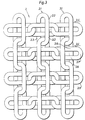
- FIG. 3 illustrates a further embodiment of the net in accordance with the invention.
- This net is generally denoted 3 and includes weft strands 3.4.
- Each warp link 3.2 locks around a weft link 3.5 and each such weft link is locked round by a warp link.
- the warp links are at 45 degrees opposed slopes to the plane of the net, while the shanks 3.6 of the weft links are in the plane of the net.
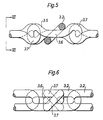
- the weft links 3.5 are formed with link shanks 3.6 pressed in opposite directions so that they can assume a position in the plane of the net, as more closely illustrated in Figures 5 and 6.
- the structure forms a relatively dense net mat and is particularly suitable in cases where relatively large stability and weight of the chain net are demanded.
- the chain net 3 can be manufactured in a similar manner and of corresponding material as for the nets 1 and 2.
- nets according to Figure 3 made from buoyant material, which may suitably be an elastically deformable plastics.
- the links can be made from plastically deformable hollow sections so that the links are thus buoyant. Due to its dense structure this net has comparatively good buoyancy in water and is therefore suitable as a floating body for different purposes.
- the warp strands can be conventional plastic chains containing links capable of the necessary elastic change in shape and return to shape, while the weft strands are suitably formed conventionally as plastic chains containing special moulded links. No special demands on elastic deformability of the weft links need to be made.
- Figure 4 shows a diagonal net 4 according to the invention.
- the warp strands 4.1 here engage with the weft strands 4.4 in the same way as the net 3.
- the warp links 4.2 slope at 45 degrees to the plane of the net and surround the weft links 4.5 with pressed link shanks 4.6, which assume a position in the plane of the net.
- the bent end portions 4.7 at the ends of the weft strands prevent the surrounding warp link from gliding off the end link of the weft strand in this case as in the previous cases.
- the diagonal net may also consist of warp and weft strands connected to each other in the same way as in the net 1 or 2.
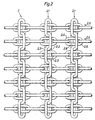
- Figures 7-12 illustrate an apparatus for manufacturing chain net in accordance with the invention with mutually parallel warp strands which are advanced in their longitudinal direction.
- the machine in question is generally denoted by 5.
- An aligning and drawing unit 7 is mounted on a bed 6 and includes two posts or guides 8 mounted vertically on either side of the manufactured net for guiding an upper vertically movable transverse beam 9.
- Vertical lifting cylinders 11 are connected to the upper ends of the guides 8 for movement of the beam 9.
- a fixed transverse beam 10 is mounted on the bed below the beam 9.
- Horizontally movable aligning slides 12, 12a provided with mutually opposing abutments 13, 13a are glidably mounted in pairs in the beams 9 and 10. The slides are operated with the aid of double-acting operating cylinders 14.
- warp links (Figure 12) which are between the slides.
- These warp links are included in warp strands (e.g. 2.1) which are advanced in the longitudinal direction of the machine and parallel to each other from a store via a roller 37 in a way described in detail below. Advancing takes place in parallel and stepwise so that the warp links simultaneously assume a position between the upper and the lower pair of aligning slides 12, 12a.
- the slides are then adjusted by the action of the cylinders 14 to a position such that the abutments 13, 13a allow the warp links to be inserted at a angle of 45 degrees, with a lower shank at a lower abutment and an upper shank at an upper abutment pertaining to the respective to slides 12, 12 directly opposite slides 12a, 12a.
- a table for weft strands e.g. 2.4.
- the table 15 is at a height such that the weft strand is on a line through the center point of the aligned warp links.
- On the opposite side of the unit 7 there is a pulling cylinder 16 directed along said line through the warp links.
- the end of the cylinder piston rod is provided with a gripping hook 17.
- the stroke of the cylinder permits the gripping hook to be taken through and past the aligned warp links to reach the end of the weft strand 2.4.
- the lifting cylinders 11 are adapted to exert an adjusting yielding pressure against the beam 9 so that the links can be erected to a vertical position under the action of the slides during yielding vertical displacement upwards of the beam 9.
- a fixed gripping unit 20 This includes an upper movable transverse beam 23 and a fixed upper transverse beam 21, the former being vertically movable along two vertical posts or guides 22.
- the guides 22 are on either side of the net and are fixed in a lower transverse beam 25 fastened to the bed.
- the upper beam 23 is vertically movable with the aid of two lifting cylinders 24 fixed to the beam 21.
- Gripping jaws 26 are mounted in the beams 23, 25 and have mutually opposing gripping surfaces suited to gripping the warp strands 2.1, as illustrated in Figure 11.
- the gripping jaws 26 are at a distance from the abutments 13, 13a corresponding to a plurality of link pitches of the warp strand 2.1.
- the unit 20 In the advancing direction of the net after the unit 20 there is an elongating or stretching apparatus of the same embodiment as the gripping unit 20, but arranged for horizontal displaca- ment along two horizontal guides 33 on either side of the net which are mounted in the transverse fixed beam 25 at one end and special brackets 34 at the other.
- the stretching or elongating unit 30 is also provided with identical gripping jaws 26 for the warp strands.
- the machine 5 is provided with a discharge roll 38 and possibly a step feeding device connected to the roll for stepwise advance of the warp strands and net through the machine.
- Warp strands (e.g. 2.1) are pulled out from a store over the rollers 37 through the aligning and drawing unit 7 to the elongation unit 30.
- the warp strands are gripped attheir ends here by the upper gripping jaw 26 being taken towards the lower gripping jaw 26 with the aid of cylinders 24.
- In this position there are a plurality of warp links between the aligning slides 12, 12a.
- the warp links are at an angle of 45 degrees in either direction of slope to the horizontal plane and the beam 9 is lowered to an adjusted height for the opened abutments 13, 13a to engage againstthe shanks ofthewarp links.
- Associated slides 12 and 12a are activated so that all the warp links are erected to a vertical position from either sloping position.
- the beam 9 is raised yieldingly to the necessary extent for this.
- the warp links are now aligned.
- the pulling cylinder 16 is actuated so that its piston rod with the gripping hook 17 is taken through the aligned warp links up to the end of the weft strand, placed on the table 15, and grips its end link.
- the gripping hook 17 is then withdrawn and thus inserts the weft strands to a suitable position in which they will be within the respective warp links for the links intended to be surrounded.
- the warp links have a dimension such that the weft strand can be inserted through these links.
- the gripping hook 17 is now disengaged from the weft strand, and the aligning slides 12,12a with the abutments 13,13a are removed from the warp strands so that these with the now-associated weft strand can be advanced further.
- This advance takes place with the aid of the elongating unit 30 and the elongating cylinders 35 to a position where the next series of warp links are in a position for alignment.
- the warp links are aligned and the next weft strand is inserted as described.
- the intersections first formed have reached the units 20 and 30 where they are gripped and retained.
- This advance suitably takes place so that the elongating unit 30 alternatingly grips and advances the warp strands one or more link pitches, after which the unit returns to repeat the advance.
- the section of the chain net between the units 20 and 30 with now-inserted weft strands is then subjected to elongation in the direction of the warp strands by the elongating unit 20 being moved in a direction away from the gripping unit 20 with the aid of the elongating cylinders 35.
- the warp links will then lock around the weft links at the intersection points on the net and the net section between the units 20 and 30 is completed.
- the advancing sequence is repeated after the net has been released from the gripping unit 20 until new warp links are in position for aligning or until a prepared section of net is between the units 20 and 30 for elongation.
- the finished net is fed out over the discharge roll 38 and may fall downwards for further handling.
- the downwardly directed part of the finished net keeps the section between either of the pairs of gripping jaws 26 and the discharging roll 38 tensioned by gravity to the necessary extent.
- the net is suitably gripped in the unit 20 when the unit 30 has released the net and is returning for a new grip.
- a special step feeding device 39 may be connected to the discharge roll 38, the elongating unit 30 then not being used for stepwise advance of the net.
- the operating cylinders for movement of the different parts of the machine can be hydraulically or pneumatically operated and controlled according to an electronically controlled operating program.
- the elongating cylinders 35 are preferably hydraulically actuated to develop the required, relatively large elongating forces.
Abstract
Description
- The present invention relates to a chain net comprising mutually intersecting chain strands with a plurality of warp strands locked to a plurality of weft strands at their intersections as shown in FR-A-1 350 323.
- Chain net in accordance with the invention forms a reticulated structure with a plurality of substantially parallel strands, hereinafter designated warp strands, which are locked to a plurality of transverse, parallel strands, hereinafter designated weft strands.
- Chain net comprising chain strands connected to each other are known in different variations. The chain strands in the net can form different patterns and be connected to each other, e.g. with the aid of special connecting loops which are inserted in the links of the chain strands and then locked. Such chain net implementations are used to a large extent as non-skid devices for vehicle tires.
- The DE Offenlegungsschrift 2 459 279 illustrates such a non-skid device including annular chain strands along either side of the tire, to which are connected transverse or diagonal chain strands, the end links of the transverse strands thrusting into links of the annular side strands and at their free ends provided with a locking means for locking to side strands.
- The DE Offenlegungsschrift 2406102 illustrates a similar non-skid device where the transverse links are terminated by a larger link with a sufficiently large inner opening to allow the side strand to be taken through it, this link then being compressed from the sides to lock the transverse strands to the side strands. A separate operation must therefore be carried out at every point of connection between the chain strands.
- The invention has the object of providing a chain net of the kind disclosed in the introduction, which has a larger number of intersections between warp and weft strands and allows efficient and economical manufacture using a commercially available chain. The chain net in accordance with the invention can be manufactured of such steel chain in normally available dimensions, but can also be manufactured from chain having links of any material with suitable plastic or elastic properties. Chain strands of any material with the required deformation properties can be used for manufacturing the inventive net, whereby greatly varying requirements for the net can be satisfied.
- A chain net of the present kind has the characterizing features disclosed in the following
claim 1. - In a preferred embodiment the warp strands consist of links with dimensions such as to allow the insertion of the weft strands through their links, these links then being deformed by elongation the warp strands such as to lock around links of the weft strands. The link shanks of the weft strands will always be in the plane of the net.
- The warp and weft strands can be combined in various ways. Every other link of the warp strand can thus be locked to every other link of the weft strand. Alternatively, each link of the warp strand can be connected to every other link of the weft strand. Finally, every link of the warp strand can be connected to every link of the weft strand. The weft strand links are then formed with link shanks pressed in opposite directions to allow these to assume a position in the plane of the net.
- The warp links are usually elongated equally as much. It is however possible to subject the warp strands to a subsequent further elongation so that a net which can, for example, have a substantially rectangular plan profile is instead bounded by opposing curved end sides at the end of the warp links. The weft strands can also be subjected to a similar subsequent elongation if so desired. When such a net, e.g. of a rectangular shape, is suspended by its corners, the net will assume a curved shape, which is advantageous in some cases when the net is to be used for taking up objects, or in using the net as a so-called blasting mat, or in other cases.
- In a particular embodiment, the chain net has a substantially rectangular plan profile, the warp strands and weft strands extending at a slope of about 45 degrees to the long sides of the profile to form a net hereinafter designated diagonal net.
- The chain net in accorance with the invention can be used to advantage as a non-skid device for vehicle tires. Such a device has in plan profile an elongated, nearly rectangular shape. The device can be implemented with longitudinal warp strands which have increased elongation towards the longitudinal centre line of the profile. The weft strands extend nearly at right angles to the warp strands. The outer warp strands will be conventionally mounted on either side of the tire and be connected with the ends opposite each other. The inner warp strands are elongated in correspondence with the increased diameter of the tire so that their respective ends meet each other for connection.
- A diagonal net for the corresponding purpose is connected on either long side to separate side strands with lengths suited to being connected at their ends in a desired position along the sides of the tire. The diagonally extending warp and weft strands will alter their mutual angular attitude on being mounted on the tire such that the entire net adjusts to the curved profile of the tire.
- When in use as a non-skid device, it is in many cases suitable for the chain strands to be provided with studs before manufacturing the net so as to achieve improved grip on the substructure. Such studs can be efficiently provided by welding studs automatically on standard chains or by using special so-called stud chain produced by conventional resistance welding of open links with bent- out end portions.
- In a still further embodiment, the chain net of the invention can include links of elastically deformable material such as plastics, rubber or the like. The warp strands are then made from the beginning with links of a configuration such that they lock around the weft links in the finished net but can assume in an elastically deformed state a configuration such that the weft strands can be inserted in the warp links. Both warp and weft strands are usually made with links of similarly elastic material, but the weft strands can alternatively be made of other material particularly suitable for the purpose. The chain net can be arranged in a varying manner in accordance with one of the patterns mentioned hereinbefore for nets with links of plastically deformable material.
- For particular purposes it may be advantageous to make these elastic nets of material having a specific gravity of less than 1, whereby the net can float on water. Such nets may be used as direct floating bodies for different purposes, and generally when the net has some task in a maritime connection and by its buoyancy does not run the risk of sinking and being lost. In the latter case it may also be suitable to make the links from plastically deformable hollow sections for accordingly making the links buoyant.
- The invention also relates to a method of manufacturing the net described hereinbefore. Characterizing for this method is that the weft strands are inserted through links in the warp strands at the intersections in the net, these warp links subsequently being caused by change of shape to lock around the weft links at the intersections. The change of shape can be achieved by warp links of plastically deformable material being elongated or by warp links of elastically deformable material being allowed to spring back into locking configuration after previously having been elastically deformed so that the weft strand can be inserted in the warp links.
- The invention also relates to an apparatus for manufacturing a chain net with characterizing features according to the following
claim 1. This apparatus includes means for the gradual, simultaneous advance of mutually parallel warp links, means for aligning a string of warp links in line with each other and with the broadsides of the links facing towards each other, means for inserting a weft strand in the thus aligned warp links and means for changing the shape of the warp links to surround weft links at the intersections in the net. - The fabricated chain net has a generally rectangular, more or less elongate configuration. When the warp links, consist, for example, of plastically deformable material and extend in the longitudinal direction of the net, the warp links are first aligned with their broadsides directly opposing each other along a line in the transverse direction of the net, subsequent to which a weft strand is drawn through these warp links. The warp strands are then elongated between fixed and movable gripping means in their longitudinal direction so that the warp links are deformed and lock around the weft links at the intersections of the net. After each elongating operation the net is advanced a number of link pitches in the longitudinal direction of the warp strands and subsequent sections of the warp strands are elongated in connection with the previously elongated sections. Advancing can be carried out with the aid of the movable elongating means or with the aid of a separate step feeding means.
- For manufacturing a net with elastically deformable warp links, an apparatus is used including abutments which are placed against the end sides of the aligned elastic warp links. After alignment according to what has been said hereinbefore, these abutments are adjusted for preliminary change of shape of the warp links so that their inner opening is enlarged and allows the insertion of the weft strand. In this position the warp links are unloaded and return to their original shape so that they surround the respective weft links and lock these at the intersections. Means for aligning the warp links, means for drawing the weft links through and means for subsequent change of form of the warp links are thus put together into a common unit in this case, and this unit can extend at right angles to the longitudinal direction of the net or diagonally across the net. The warp strands are then fed in mutually parallel in their longitudinal direction or moved parallel as described for manufacturing diagonal net.
- The invention is described below in the form of an embodiment and with reference to the accompanying drawings which illustrate the chain net in accordance with the invention in different variants, as well as apparatus for making the net.
- Figure 1 illustrates a chain net with intersections at alternate links of the warp and weft strands.
- Figure 2 illustrates a chain net with intersections at every link of the warp strands and alternate links of the weft strands.
- Figure 3 illustrates a chain net with intersections at every link of the warp and weft strands.
- Figure 4 illustrates a diagonal net with intersections at every link of the warp and weft strands.
- Figure 5 illustrates a weft strand formed for intersections at every link of the weft strand.
- Figure 6 illustrates this link seen along the line VI-VI in Figure 5.
- Figure 7 is a plan of an apparatus for manufacturing chain net with advance of the warp strands in their longitudinal direction.
- Figure 8 is a side view of this apparatus, partially in section, along the line VIII-VIII in Figure 7.
- Figure 9 illustrates the apparatus seen along the line IX-IX in Figure 8.
- Figure 10 is a section along the line X-X in Figure 8.
- Figure 11 is a detail to a larger scale of the gripping means for elongating the chain net.
- Figure 12 is a detail to a larger scale of the aligning means for warp links.
- Figure 1 illustrates a chain net, generally denoted by the
numeral 1, in accordance with the invention in a first embodiment. The net comprises a plurality of mutually parallel warp strands 1.1 made from commercially available chain and containing warp links 1.2 with warp link shanks 1.3 and a plurality of crossing weft strands 1.4 made from similarly commercially available chain containing weft links 1.5 with link shanks 1.6. Alternate warp links 1.2 are locked round the shanks of alternate weft links 1.5. The weft link is locked between the end portions of adjacent warp links and adjacent weft links. All the shanks 1.6 of the weft links are in a plane common with the net. - To provide the mentioned lock between warp and weft strands the warp links are deformed after the weft strands have been taken through the warp links. This lock and deformation can be carried out in two different ways, namely:
- a) a warp strand containing plastically deformable links with-sufficient inner opening for allowing insertion of the weft strand has been deformed by elongating the warp strand,
- b) a warp strand containing elastically deformable links has been given a change of shape by pressure against the end portions of the link so that its inner opening has been enlarged sufficiently for allowing insertion of a weft strand, after which the pressure has been removed so that the warp link returns by its own elasticity to its original shape to lock round the weft link.
- It will be noted that all links in both warp and weft strands are all the same in the finished net. The warp strands can be made, for example, from ordinary commercial steel chain, but in case of need can be also made from chain strands containing links of some other plastically deformable material which allows the necessary permanent deformation by elongating the link in its longitudinal direction to surround the weft link. The material in the warp links can thus be alloyed or unalloyed steel, stainless steel, bronze, brass, aluminium, aluminium alloy or similarly plastically deformable material.
- The weft strands are also preferably made from the same material as the warp strands, but may also be made from some other material in the case where there is some reason for this to be suitable. Since the weft strands are not usually deformed, there is greater freedom in the selection of material for them.
- For practical reasons the net is made with an elongate rectangular plan profile and can be manufactured practically unlimited in length. The width of the net can vary in practice, a greatest width in the order of magnitude of 1 meter can usually be suitable, but even greater widths can of course occur. Should there be a need of greater widths, two nets can be coupled together along their long sides without any problems with the aid of suitable locking means which are inserted in the mutually opposing end links of the weft strands.
- In certain cases it is suitable to subject the warp strands to varying elongation. For example, when the net is to be used as a non-skid device, and thus includes two sides strands intended to be mounted annularly on either side of a vehicle tire, with annular warp strands therebetween positioned at different diameters along the arched thread of the tire, there being transverse weft strands extending between the side strands, the intermediate warp strands must have successively increasing length towards the middle of the tire. Such a net is suitably manufactured starting from an already finished rectangular net. The warp strands situated between the long sides of the net being subjected to further elongation to the required length. Such further elongation is carried out with the aid of suitable conventional apparatus on each warp strand individually.
- For certain purposes it may also be suitable to subject the weft strands to a subsequent similar elongation towards successively increased length towards the middle of the net. Such a net is given a bowl shape between its straight long sides and end sides. This bowl shape is particularly suitable in cases where the net is to cover a correspondingly bowl shaped sub-structure, e.g. for use as a damping net or so-called blasting mat in blasting work.
- A particularly advantageous use of elongate rectangular nets with transverse weft strands is as caterpillar tracks for crawler vehicles, the weft strands engaging in corresonding grooves on the driving wheels of the vehicle.
- To increase friction against the sub-structure for both non-skid devices and caterpillar tracks, the warp and weft strands can be provided to a suitable extent with projections or studs. The chain strands used can be provided beforehand with welded-on studs during manufacture, or such studs can be formed by resistance welding if the chain strands by means of the chain link being formed with bent-over ends before the final welding together.
- Figure 2 illustrates a further embodiment of the chain net in accordance with the invention. This net is generally denoted by 2. Each link 2.2 of the warp strands 2.1 surrounds alternate links 2.5 of the weft strands 2.4. In this case, the warp links are disposed at 45 degrees in successively opposing slopes towards the plane of the net, while the weft links 2.5 have their shanks 2.6 in the plane of the net. The shanks 2.3 of the warp links 2.2 are in this case closer to, or engage against, the weft shanks 2.6, the lock thus being tighter and with less play. The net 2 thus becomes less flexible than the more loosely
jointed net 1. For the remainder, thenet 2 has similar properties and possibilities of use as thenet 1 and is manufactured in principally the same way from corresponding material. - Figure 3 illustrates a further embodiment of the net in accordance with the invention. This net is generally denoted 3 and includes weft strands 3.4. Each warp link 3.2 locks around a weft link 3.5 and each such weft link is locked round by a warp link. As in the previous case, the warp links are at 45 degrees opposed slopes to the plane of the net, while the shanks 3.6 of the weft links are in the plane of the net. To enable this, the weft links 3.5 are formed with link shanks 3.6 pressed in opposite directions so that they can assume a position in the plane of the net, as more closely illustrated in Figures 5 and 6. The structure forms a relatively dense net mat and is particularly suitable in cases where relatively large stability and weight of the chain net are demanded.
- The
chain net 3 can be manufactured in a similar manner and of corresponding material as for thenets - Figure 4 shows a diagonal net 4 according to the invention. The warp strands 4.1 here engage with the weft strands 4.4 in the same way as the
net 3. The warp links 4.2 slope at 45 degrees to the plane of the net and surround the weft links 4.5 with pressed link shanks 4.6, which assume a position in the plane of the net. The bent end portions 4.7 at the ends of the weft strands prevent the surrounding warp link from gliding off the end link of the weft strand in this case as in the previous cases. - The diagonal net may also consist of warp and weft strands connected to each other in the same way as in the net 1 or 2.
- Figures 7-12 illustrate an apparatus for manufacturing chain net in accordance with the invention with mutually parallel warp strands which are advanced in their longitudinal direction. The machine in question is generally denoted by 5. An aligning and
drawing unit 7 is mounted on abed 6 and includes two posts or guides 8 mounted vertically on either side of the manufactured net for guiding an upper vertically movabletransverse beam 9.Vertical lifting cylinders 11 are connected to the upper ends of theguides 8 for movement of thebeam 9. A fixedtransverse beam 10 is mounted on the bed below thebeam 9. Horizontally movable aligningslides abutments beams operating cylinders 14. Theabutments roller 37 in a way described in detail below. Advancing takes place in parallel and stepwise so that the warp links simultaneously assume a position between the upper and the lower pair of aligningslides cylinders 14 to a position such that theabutments slides opposite slides unit 7 there is a table for weft strands, e.g. 2.4. The table 15 is at a height such that the weft strand is on a line through the center point of the aligned warp links. On the opposite side of theunit 7 there is a pullingcylinder 16 directed along said line through the warp links. The end of the cylinder piston rod is provided with agripping hook 17. The stroke of the cylinder permits the gripping hook to be taken through and past the aligned warp links to reach the end of the weft strand 2.4. When the warp links are aligned with the aid of theslides cylinders 11 are adapted to exert an adjusting yielding pressure against thebeam 9 so that the links can be erected to a vertical position under the action of the slides during yielding vertical displacement upwards of thebeam 9. - After the
unit 7 in the advancing direction of the net there is a fixedgripping unit 20. This includes an upper movabletransverse beam 23 and a fixed uppertransverse beam 21, the former being vertically movable along two vertical posts or guides 22. Theguides 22 are on either side of the net and are fixed in a lowertransverse beam 25 fastened to the bed. Theupper beam 23 is vertically movable with the aid of two liftingcylinders 24 fixed to thebeam 21. Grippingjaws 26 are mounted in thebeams jaws 26 are at a distance from theabutments - In the advancing direction of the net after the
unit 20 there is an elongating or stretching apparatus of the same embodiment as the grippingunit 20, but arranged for horizontal displaca- ment along twohorizontal guides 33 on either side of the net which are mounted in the transverse fixedbeam 25 at one end andspecial brackets 34 at the other. The elongation or stretchingunit 30, in contradistinction to the grippingunit 20, thus has a lowermovable beam 32 and movablevertical posts 31 while remaining parts are identical. The stretching or elongatingunit 30 is also provided with identicalgripping jaws 26 for the warp strands. Between the grippingunit 20 and the elongatingunit 30 there are two elongatingcylinders 35 on either side of the machine, with which the elongating unit can be moved horizontally for elongating the warp links between the grippingunit 20 and the elongatingunit 30. - Finally, the
machine 5 is provided with adischarge roll 38 and possibly a step feeding device connected to the roll for stepwise advance of the warp strands and net through the machine. - The apparatus functions in the following manner. Warp strands, (e.g. 2.1) are pulled out from a store over the
rollers 37 through the aligning anddrawing unit 7 to theelongation unit 30. The warp strands are gripped attheir ends here by the uppergripping jaw 26 being taken towards the lowergripping jaw 26 with the aid ofcylinders 24. In this position there are a plurality of warp links between the aligning slides 12, 12a. In the manufacture of atype 2 netthe warp links are at an angle of 45 degrees in either direction of slope to the horizontal plane and thebeam 9 is lowered to an adjusted height for the openedabutments beam 9 is raised yieldingly to the necessary extent for this. The warp links are now aligned. The pullingcylinder 16 is actuated so that its piston rod with the grippinghook 17 is taken through the aligned warp links up to the end of the weft strand, placed on the table 15, and grips its end link. The grippinghook 17 is then withdrawn and thus inserts the weft strands to a suitable position in which they will be within the respective warp links for the links intended to be surrounded. The warp links have a dimension such that the weft strand can be inserted through these links. - The gripping
hook 17 is now disengaged from the weft strand, and the aligning slides 12,12a with theabutments unit 30 and the elongatingcylinders 35 to a position where the next series of warp links are in a position for alignment. The warp links are aligned and the next weft strand is inserted as described. After renewed advancing of the necessary number of pitches, the intersections first formed have reached theunits unit 30 alternatingly grips and advances the warp strands one or more link pitches, after which the unit returns to repeat the advance. The section of the chain net between theunits unit 20 being moved in a direction away from the grippingunit 20 with the aid of the elongatingcylinders 35. - The warp links will then lock around the weft links at the intersection points on the net and the net section between the
units unit 20 until new warp links are in position for aligning or until a prepared section of net is between theunits discharge roll 38 and may fall downwards for further handling. In continuation, the downwardly directed part of the finished net keeps the section between either of the pairs of grippingjaws 26 and the dischargingroll 38 tensioned by gravity to the necessary extent. In the stepwise advance the net is suitably gripped in theunit 20 when theunit 30 has released the net and is returning for a new grip. - Alternatively, a special
step feeding device 39 may be connected to thedischarge roll 38, the elongatingunit 30 then not being used for stepwise advance of the net. - The operating cylinders for movement of the different parts of the machine can be hydraulically or pneumatically operated and controlled according to an electronically controlled operating program. The elongating
cylinders 35 are preferably hydraulically actuated to develop the required, relatively large elongating forces.
Claims (12)
Priority Applications (1)
| Application Number | Priority Date | Filing Date | Title |
|---|---|---|---|
| AT84850213T ATE49541T1 (en) | 1983-07-26 | 1984-07-06 | CHAINNET. |
Applications Claiming Priority (2)
| Application Number | Priority Date | Filing Date | Title |
|---|---|---|---|
| SE8304140 | 1983-07-26 | ||
| SE8304140A SE441511B (en) | 1983-07-26 | 1983-07-26 | CHAIN NETWORK AND SET AND APPARATUS FOR MANUFACTURING THE CHAIN NET |
Publications (3)
| Publication Number | Publication Date |
|---|---|
| EP0133171A2 EP0133171A2 (en) | 1985-02-13 |
| EP0133171A3 EP0133171A3 (en) | 1988-03-16 |
| EP0133171B1 true EP0133171B1 (en) | 1990-01-17 |
Family
ID=20352055
Family Applications (1)
| Application Number | Title | Priority Date | Filing Date |
|---|---|---|---|
| EP19840850213 Expired - Lifetime EP0133171B1 (en) | 1983-07-26 | 1984-07-06 | Chain net |
Country Status (6)
| Country | Link |
|---|---|
| US (1) | US4673015A (en) |
| EP (1) | EP0133171B1 (en) |
| AT (1) | ATE49541T1 (en) |
| DE (1) | DE3481042D1 (en) |
| FI (1) | FI78424C (en) |
| SE (1) | SE441511B (en) |
Families Citing this family (13)
| Publication number | Priority date | Publication date | Assignee | Title |
|---|---|---|---|---|
| US4872306A (en) * | 1987-07-24 | 1989-10-10 | Cooper Industries, Inc. | Method of fabricating chain mesh and chain mesh fabricated thereby |
| US4869061A (en) * | 1987-07-24 | 1989-09-26 | Cooper Industries, Inc. | Method of fabricating chain mesh and chain mesh fabricated thereby |
| US6391420B1 (en) | 1992-02-28 | 2002-05-21 | Leucadia, Inc. | Bicomponent elastomeric netting |
| SE510559C2 (en) * | 1994-07-07 | 1999-06-07 | Olof Andreasson | Wheels for feeding elongated objects such as tree trunks |
| US5885686A (en) * | 1994-08-26 | 1999-03-23 | Leucadia, Inc. | Bicomponent elastomeric netting |
| US6204207B1 (en) | 1996-08-01 | 2001-03-20 | Leucadia, Inc. | Extruded netting exhibiting stretch and bonding |
| IT1307836B1 (en) * | 1999-01-26 | 2001-11-19 | Orlando Orlandini | MANUFACTURE FOR CLOTHING, CLOTHING ACCESSORIES, JEWELERY, BAGS AND MORE, CONSISTING OF A FRAME FABRIC WITH CHAINS IN REPLACEMENT OF |
| GB9926195D0 (en) * | 1999-11-05 | 2000-01-12 | Johnson Ivor G | Fish grading device |
| US6837037B2 (en) * | 2003-01-22 | 2005-01-04 | Jonathan Willinger | Interconnected rubber ring chain |
| WO2009115361A1 (en) * | 2008-03-19 | 2009-09-24 | Nv Bekaert Sa | Aquaculture net with polygonal bottom |
| AT511844B1 (en) * | 2012-03-01 | 2013-03-15 | Pewag Schneeketten Gmbh & Co Kg | Chain for mounting on a vehicle tire |
| US9545773B2 (en) | 2013-03-15 | 2017-01-17 | Albany International Corp. | Pad comprising an extruded mesh and method of making thereof |
| US9352530B2 (en) | 2013-03-15 | 2016-05-31 | Albany International Corp. | Industrial fabric comprising an extruded mesh and method of making thereof |
Family Cites Families (11)
| Publication number | Priority date | Publication date | Assignee | Title |
|---|---|---|---|---|
| US1050216A (en) * | 1906-06-12 | 1913-01-14 | Charles Holl | Ring fabric. |
| US1016479A (en) * | 1911-08-03 | 1912-02-06 | Sebree Mail Exchanging Device Co | Railway mail catching and delivering apparatus. |
| US1467927A (en) * | 1921-03-12 | 1923-09-11 | Ralph N Doerres | Antiskid chain |
| US1458096A (en) * | 1922-11-06 | 1923-06-05 | Emerson E Garrett | Chain |
| US3087527A (en) * | 1961-03-20 | 1963-04-30 | William A Crider | Traction device for vehicles |
| FR1350323A (en) * | 1962-05-17 | 1964-01-24 | Otto Bornemann & Co K G | Tire protection chain |
| US3662539A (en) * | 1968-10-16 | 1972-05-16 | Peter Florjancic | Injection moulded chain, especially plastic chain |
| DE2406102A1 (en) * | 1974-02-05 | 1975-08-07 | Rud Ketten Rieger & Dietz | Snow chain for car tyre - with vertical links clipped to collection points and crimped |
| DE2459279A1 (en) * | 1974-12-14 | 1976-06-16 | Erlau Ag Eisen Drahtwerk | Coupling link for snow chain - with flat oval link to slide through side strands and secure cross chains |
| US4349060A (en) * | 1980-03-19 | 1982-09-14 | Elkem A/S | Means for improving the surface grip of a tire of a vehicle and a method for manufacturing such means |
| US4361178A (en) * | 1981-01-27 | 1982-11-30 | Gower Roger L | Straight link studded tire chain |
-
1983
- 1983-07-26 SE SE8304140A patent/SE441511B/en not_active IP Right Cessation
-
1984
- 1984-07-06 EP EP19840850213 patent/EP0133171B1/en not_active Expired - Lifetime
- 1984-07-06 AT AT84850213T patent/ATE49541T1/en not_active IP Right Cessation
- 1984-07-06 DE DE8484850213T patent/DE3481042D1/en not_active Expired - Lifetime
- 1984-07-12 US US06/630,089 patent/US4673015A/en not_active Expired - Fee Related
- 1984-07-13 FI FI842826A patent/FI78424C/en not_active IP Right Cessation
Also Published As
| Publication number | Publication date |
|---|---|
| FI842826A (en) | 1985-01-27 |
| FI842826A0 (en) | 1984-07-13 |
| FI78424C (en) | 1989-08-10 |
| EP0133171A3 (en) | 1988-03-16 |
| DE3481042D1 (en) | 1990-02-22 |
| SE8304140D0 (en) | 1983-07-26 |
| FI78424B (en) | 1989-04-28 |
| US4673015A (en) | 1987-06-16 |
| EP0133171A2 (en) | 1985-02-13 |
| SE8304140L (en) | 1985-01-27 |
| SE441511B (en) | 1985-10-14 |
| ATE49541T1 (en) | 1990-02-15 |
Similar Documents
| Publication | Publication Date | Title |
|---|---|---|
| EP0133171B1 (en) | Chain net | |
| AU2005251879B2 (en) | Protective mesh in particular for rockfall protection or for slope stabilisation | |
| HU226386B1 (en) | Woven wire netting for protection against rock falls or for securing a top layer of soil, and method and device for producing same | |
| US20070131917A1 (en) | Protective mesh, especially for rockfall protection or to stabilise a layer of soil | |
| US9579710B2 (en) | Self-furring welded wire mesh | |
| GB1571296A (en) | Method of and apparatus for forming nets | |
| DE19705713A1 (en) | Fabric pillar bag for foundations | |
| DE1659192A1 (en) | Spacers for concrete reinforcement rods or the like. | |
| DE1804474A1 (en) | Stand for hop cultures | |
| US4439908A (en) | Method for stringing a racquet | |
| AT203043B (en) | Resilient guard | |
| DE1962861A1 (en) | High-strength steel wire band rope | |
| DE3803498A1 (en) | DEVICE FOR THE PRODUCTION OF JEWELERY CHAINS, IN PARTICULAR SO-PLANNING EYE CHAINS | |
| DE3838183A1 (en) | Method for making long splices | |
| GB2188652A (en) | Connection of a support rope to a net | |
| DE1758677C (en) | Pneumatic support cushion for the construction of underground cavities | |
| US20030009962A1 (en) | Method and apparatus for post-tensioning steel strands in slab construction | |
| AU607562B2 (en) | Mining equipment extraction device | |
| DE2547282A1 (en) | METHOD AND DEVICE FOR PLACING OBJECTS IN A PRESET ARRANGEMENT | |
| SE442811B (en) | FLASH WITH WOVEN BERBAND AND WOVEN HECTOR ORGAN | |
| TH14209EX (en) | Methods for picking up the strings used in sports. | |
| EP0204388B1 (en) | Device for manufacturing a block mat | |
| WO2003060237A1 (en) | Afforestation and snow-slip preventer | |
| DE1924312A1 (en) | Method and device for producing a suspended roof | |
| IE45002B1 (en) | Wire fencing |
Legal Events
| Date | Code | Title | Description |
|---|---|---|---|
| PUAI | Public reference made under article 153(3) epc to a published international application that has entered the european phase |
Free format text: ORIGINAL CODE: 0009012 |
|
| AK | Designated contracting states |
Designated state(s): AT CH DE FR IT LI |
|
| PUAL | Search report despatched |
Free format text: ORIGINAL CODE: 0009013 |
|
| AK | Designated contracting states |
Kind code of ref document: A3 Designated state(s): AT CH DE FR IT LI |
|
| 17P | Request for examination filed |
Effective date: 19880510 |
|
| 17Q | First examination report despatched |
Effective date: 19890612 |
|
| RAP3 | Party data changed (applicant data changed or rights of an application transferred) |
Owner name: ANDREASSON, OLOF INGVAR |
|
| GRAA | (expected) grant |
Free format text: ORIGINAL CODE: 0009210 |
|
| ITF | It: translation for a ep patent filed |
Owner name: STUDIO D'ORIO |
|
| AK | Designated contracting states |
Kind code of ref document: B1 Designated state(s): AT CH DE FR IT LI |
|
| REF | Corresponds to: |
Ref document number: 49541 Country of ref document: AT Date of ref document: 19900215 Kind code of ref document: T |
|
| ET | Fr: translation filed | ||
| REF | Corresponds to: |
Ref document number: 3481042 Country of ref document: DE Date of ref document: 19900222 |
|
| PLBE | No opposition filed within time limit |
Free format text: ORIGINAL CODE: 0009261 |
|
| STAA | Information on the status of an ep patent application or granted ep patent |
Free format text: STATUS: NO OPPOSITION FILED WITHIN TIME LIMIT |
|
| 26N | No opposition filed | ||
| ITTA | It: last paid annual fee | ||
| PGFP | Annual fee paid to national office [announced via postgrant information from national office to epo] |
Ref country code: AT Payment date: 19940711 Year of fee payment: 11 |
|
| PGFP | Annual fee paid to national office [announced via postgrant information from national office to epo] |
Ref country code: CH Payment date: 19940712 Year of fee payment: 11 |
|
| PGFP | Annual fee paid to national office [announced via postgrant information from national office to epo] |
Ref country code: DE Payment date: 19940714 Year of fee payment: 11 |
|
| PGFP | Annual fee paid to national office [announced via postgrant information from national office to epo] |
Ref country code: FR Payment date: 19940720 Year of fee payment: 11 |
|
| PG25 | Lapsed in a contracting state [announced via postgrant information from national office to epo] |
Ref country code: AT Effective date: 19950706 |
|
| PG25 | Lapsed in a contracting state [announced via postgrant information from national office to epo] |
Ref country code: LI Effective date: 19950731 Ref country code: CH Effective date: 19950731 |
|
| REG | Reference to a national code |
Ref country code: CH Ref legal event code: PL |
|
| PG25 | Lapsed in a contracting state [announced via postgrant information from national office to epo] |
Ref country code: DE Effective date: 19960402 |
|
| PG25 | Lapsed in a contracting state [announced via postgrant information from national office to epo] |
Ref country code: FR Effective date: 19960430 |
|
| REG | Reference to a national code |
Ref country code: FR Ref legal event code: ST |
|
| REG | Reference to a national code |
Ref country code: FR Ref legal event code: ST |
|
| REG | Reference to a national code |
Ref country code: FR Ref legal event code: ST |