EP0133007A2 - Movable ultrasonic transducer array - Google Patents
Movable ultrasonic transducer array Download PDFInfo
- Publication number
- EP0133007A2 EP0133007A2 EP84305012A EP84305012A EP0133007A2 EP 0133007 A2 EP0133007 A2 EP 0133007A2 EP 84305012 A EP84305012 A EP 84305012A EP 84305012 A EP84305012 A EP 84305012A EP 0133007 A2 EP0133007 A2 EP 0133007A2
- Authority
- EP
- European Patent Office
- Prior art keywords
- array
- transducer
- ultrasonic
- cell
- support
- Prior art date
- Legal status (The legal status is an assumption and is not a legal conclusion. Google has not performed a legal analysis and makes no representation as to the accuracy of the status listed.)
- Granted
Links
Images

Classifications
-
- G—PHYSICS
- G01—MEASURING; TESTING
- G01N—INVESTIGATING OR ANALYSING MATERIALS BY DETERMINING THEIR CHEMICAL OR PHYSICAL PROPERTIES
- G01N29/00—Investigating or analysing materials by the use of ultrasonic, sonic or infrasonic waves; Visualisation of the interior of objects by transmitting ultrasonic or sonic waves through the object
- G01N29/22—Details, e.g. general constructional or apparatus details
- G01N29/26—Arrangements for orientation or scanning by relative movement of the head and the sensor
- G01N29/265—Arrangements for orientation or scanning by relative movement of the head and the sensor by moving the sensor relative to a stationary material
-
- B—PERFORMING OPERATIONS; TRANSPORTING
- B23—MACHINE TOOLS; METAL-WORKING NOT OTHERWISE PROVIDED FOR
- B23Q—DETAILS, COMPONENTS, OR ACCESSORIES FOR MACHINE TOOLS, e.g. ARRANGEMENTS FOR COPYING OR CONTROLLING; MACHINE TOOLS IN GENERAL CHARACTERISED BY THE CONSTRUCTION OF PARTICULAR DETAILS OR COMPONENTS; COMBINATIONS OR ASSOCIATIONS OF METAL-WORKING MACHINES, NOT DIRECTED TO A PARTICULAR RESULT
- B23Q1/00—Members which are comprised in the general build-up of a form of machine, particularly relatively large fixed members
- B23Q1/25—Movable or adjustable work or tool supports
- B23Q1/44—Movable or adjustable work or tool supports using particular mechanisms
- B23Q1/50—Movable or adjustable work or tool supports using particular mechanisms with rotating pairs only, the rotating pairs being the first two elements of the mechanism
- B23Q1/54—Movable or adjustable work or tool supports using particular mechanisms with rotating pairs only, the rotating pairs being the first two elements of the mechanism two rotating pairs only
- B23Q1/5468—Movable or adjustable work or tool supports using particular mechanisms with rotating pairs only, the rotating pairs being the first two elements of the mechanism two rotating pairs only a single rotating pair followed parallelly by a single rotating pair
-
- G—PHYSICS
- G01—MEASURING; TESTING
- G01N—INVESTIGATING OR ANALYSING MATERIALS BY DETERMINING THEIR CHEMICAL OR PHYSICAL PROPERTIES
- G01N29/00—Investigating or analysing materials by the use of ultrasonic, sonic or infrasonic waves; Visualisation of the interior of objects by transmitting ultrasonic or sonic waves through the object
- G01N29/04—Analysing solids
- G01N29/06—Visualisation of the interior, e.g. acoustic microscopy
- G01N29/0609—Display arrangements, e.g. colour displays
- G01N29/0618—Display arrangements, e.g. colour displays synchronised with scanning, e.g. in real-time
-
- G—PHYSICS
- G10—MUSICAL INSTRUMENTS; ACOUSTICS
- G10K—SOUND-PRODUCING DEVICES; METHODS OR DEVICES FOR PROTECTING AGAINST, OR FOR DAMPING, NOISE OR OTHER ACOUSTIC WAVES IN GENERAL; ACOUSTICS NOT OTHERWISE PROVIDED FOR
- G10K11/00—Methods or devices for transmitting, conducting or directing sound in general; Methods or devices for protecting against, or for damping, noise or other acoustic waves in general
- G10K11/18—Methods or devices for transmitting, conducting or directing sound
- G10K11/26—Sound-focusing or directing, e.g. scanning
- G10K11/35—Sound-focusing or directing, e.g. scanning using mechanical steering of transducers or their beams
- G10K11/352—Sound-focusing or directing, e.g. scanning using mechanical steering of transducers or their beams by moving the transducer
Definitions
- This invention relates to an apparatus and method for non-destructively inspecting various bodies or objects using a moving transducer array, specifically in combination with a liquid crystal ultrasonic detector cell.
- Ultrasonic examination of various bodies or objects is well known in both the medical and industrial fields.
- an ultrasonic transducer is provided which emits an insonifying ultrasonic beam which is directed to an object.
- the ultrasonic beam passes through the object, is received by a detector and an image is generated.
- Liquid crystal detector cells which display an image are disclosed in various U.S. patents. See, for example, U.S. Patents No. 4,379,408; 4,338,821; 3,579,054; 3,707,323; 3,831,434; and 3,879,989.
- the ultrasonic transducer may be a single transducer which is held in position or a plurality of transducers held in position which are seguentially excited so as to produce an image.
- Rotatable wheels have been suggested for inspecting larger objects in which transducers are aligned along the radii of the wheel and are carried on the circumference or the periphery of the wheel so as to contact the object as the wheel is rolled. See for example, U.S. Patents No. 3,423,994; 3,541,840; and 3,771,354. These devices are believed to be too cumbersome, not sufficiently flexible in their use and do not appear to be adaptable for use with liquid crystal detectors.
- a rotating transducer array is shown in U.S. Patent No. 3,280,621 in which the sending transducers are focused at a point on the axis of rotation and the receiving transducer is mounted on the axis of rotation for receiving reflected signals.
- this device is not believed to be suitable for use in inspecting large objects. Furthermore, this device is not intended for use with a liquid crystal display cell.
- a novable, ultrasonic transducer array which is suitable for use with a liquid crystal display and which provides a large uniform insonifying beam that is suitable for use in inspecting large objects and sections of large objects such as aircraft wings, and the like.
- a transducer array which includes a plurality of sending ultrasonic transducers mounted to a support member with the transmission or radiation axes of the transducers being in substantially parallel alignment.
- Drive means are provided for moving the array and support along a predetermined path in a periodic manner.
- drive and linkage means are provided for rotating an array about an axis spaced from the geometric center of the array, but within the periphery of the array, and with the transducers maintaining their relative vertical and horizontal positions.
- This may be characterized as an eccentric movement of the array.
- the array is rotated about an axis which is spaced from the geometric center of the array, but in that arrangement, the transducers do not maintain their horizontal and vertical orientations relative to each other.
- the rotation is provided by a ring and pinion gear assembly to which the transducer array is mounted and may be characterized as a planetary-type movement.
- Horizontal and vertical translation of the array is also suitable, so long as the axis of the transmitting transducers remain parallel to prior position.
- the angular relation between the liquid crystal cell and inci - dent ultrasonic radiation from the inspected body is maintained substantially constant.
- a typical ultrasonic inspection apparatus 1.0 generally, which includes a bath 12, usually water, within which a transducer 14, an object 16, and liquid crystal detector cell 18 are positioned and acoustically coupled.
- the transducer 14 insonifies the object 16 and energy exiting the object is incident on the cell 18.
- the cell converts the incident energy to a visible image which can be seen by the viewer 19.
- Numerous optical systems can be provided for viewing the image and various different cell constructions can be used.
- U.S. Patent No. 4,379,408 discloses a laminated type of liquid crystal detector cell.
- the transducer 14 may be an array or plurality of transducers which is moved by a motor 20. Both the motor and transducer obtain their power from source 22.
- Averaging effect is intended to mean that each portion of the test area is insonified by acoustic energy of substantially the same intensity over an average period of time.
- FIG. 2 One embodiment of a movable transducer array is shown in Figures 2, 3 and 4.
- the motor 20 is mounted to a fixed or stationary frame (not shown) as are the support plates 24 and 26.
- a pair of rotatable shafts 28 and 30 are journalled to the plates and each carries a sprocket gear 32 and 34.
- a drive chain 36 is trained about the motor drive sprocket 38 and about the driven sprockets 32 and 34. Rotation of the motor sprocket 38 drives the sprockets 32 and 34 and turns the axles or shafts 28 and 30.
- a pair of links 40 and 42 are also provided and each is secured at one end to the forward terminal end of each of the axles or shafts 28 or 30.
- the other end of each of the links 40 and 42 is journalled to a support plate 44 via bearings 46 and 48.
- the support member 44 includes a disc-shaped transducer carrier 50 in which seven sending or emitting transducers 52, 54, 56, 58, 60, 62 and 64 are positioned. It will be noted that there is a central transducer and six transducers spaced thereabout in a hexagonal close-packed arrangement. As can be seen, the faces of all of the transducers lie in substantially the same plane and the radiation or transmission axis of each of the transducers are parallel to one another.
- the transducer faces move in substantially the same plane and the transducer axes all remains parallel to one another.
- the path of movement is substantially circular and caused by the eccentric movement of the drive and linkages.
- the geometric center of the array which passes through the center of transducer 64 is offset from the center of movement for the entire array. However, the center of movement is still within the periphery of the array itself, thus avoiding dead spots or uninsonified areas.
- FIG 4 The parallel positioning of the axes of the transducers is seen in Figure 4 as is the offset between the geometric center of the transducers 68 and the axis of rotation 70.
- Figure 4 shows a more detailed view of the bearings 72, 74 and 76 which support the drive axles.
- the support plate journal points such as 46 and 48 are seen.
- transducers such as 56 and 62, while they are in fact sweeping in a circular path, remain in the same vertical and horizontal or spatial relationship to each other.
- the power source 22 can be connected directly to the transducer without twisting or damaging any of the connecting lines.
- This embodiment produces a substantially uniform insonifying ultrasonic beam which is capable of insonifying large objects or sections of large objects. For example, a large graphite/epoxy panel was inspected with a beam having a 50-square inch area.
- the transducer radiation axes can be at an angle, perhaps 10°, to the plane of array movement, so long as all axes are substantially parallel to each other.
- the embodiment described herein can be used with transducers where the axes are normal to the plane of movement or skewed relative to the plane of movement.
- a drive motor 20 which drives the chain 100 that is connected to a single driven sprocket 102.
- the sprocket 102 is supported on a shaft 104 that is journalled and supported from a stationary support plate 106.
- the shaft 104 extends forwardly of the support plate 106 and carries a Neoprene seal 108, bushing 110, 24-tooth pinion gear 112, and terminates with a bushing 114.
- the plate 106 and shaft 104 provide a portion of a stationary section which includes the stationary back plate 116 and stationary front plate 118.
- the power source 22 is connected through a bushing-like structure 120 to a commutator assembly 121 which is also stationary.
- the commutator includes a pair of electrically conducting brushes 121a and 121b.
- the foregoing elements define a stationary structure which is fixed in place relative to the frame or tank which is being used. Those elements are shown in Figure 6 with diagonal lines extending from an upper left position to a lower right position and include plate 106, plate 116, plates 114 and 118. The same elements are shown in elevation in Figure 7. Thus the shaft 104 is maintained in position even though it is rotating within the stationary structure.
- the rotatable portions include a cup-like housing member 122 generally, which supports the transducer array 124 generally.
- the stationary portion remains in position and rotation of the pinion gear 112 causes the cup-like member, and thus the transducer array, to rotate about an axis.
- the axis of rotation 126 is spaced from the geometric center of the array 128, and so long as the center of rotation 126 is within the geometric periphery of the array, a substantially uniform or averaged beam will be provided.
- the cup-like member 122 includes a flat front wall 130 and a cylindrical side wall 132 which extends rearwardly therefrom and encloses portions of the stationary member.
- the rotary member is mounted to the stationary member by a bearing 134 which is positioned between the side wall 132 and the stationary plate 118.
- Peripheral seals 136 are also provided to seal the interior of cup-shaped assembly.
- a 96-tooth ring gear 138 is mounted to the rotary member and is positioned for engagement by the pinion gear 112.
- a rotating commutator or slip ring assembly 140 is provided for electrical contact with the brushes 121a and 121b.
- the slip ring is positioned adjacent the back edge of the front plate 130.
- Metal shielding members such as 142 and 144, are provided about the slip ring assembly so as to suppress extraneous electrical signals due to the operation of the commutator assembly 121.
- a copper-plated disc 146 is supported from the assembly 140 for engagement by the brushes 121a and 121b.
- the transducer array 126 is mounted to the front face of the plate 130 and carries seven sending or transmitting transducers 152, 154, 156, 158, 160, 162 and 164. These are arranged with a central transducer and six transducers positioned in a hexagonal close-packed arrangement thereabout.
- the motor 20 drives the chain 100, which in turn causes the shaft 104 and pinion gear 112 to rotate.
- Rotation of the pinion gear causes the housing 122 to rotate due to the interaction of the pinion gear 112 and ring gear 138.
- Power is continuously supplied to the transducers via line 120 which connects to the commutator assembly 121, and in turn to the slip ring disc 146 and through lines 148 and 150 to common connections through the transducer.
- the axis of rotation for the rotating portion of the housing is at the center of the ring gear which is indicated by the axis 126.
- the transducers also change their relative or spatial positions. This is unlike the first described embodiment. More specifically, the transducer 162, which is shown at the 6 o'clock position in Figure 5, will move to the 9 o'clock position, and then the 12 o'clock position as shown by dotted lines in Figure 5. This is in a sense a planetary-type of movement.
- the radiation axes are parallel to each other and normal to the plane or rotation.
- a predetermined path such as a linear path or a curved path.
- the transducers could be moved along a horizontal line from one extreme to a second extreme and then back.
- an array 200. of four square transducers can be moved back and forth along rails, such as 202 and 204, to scan the object 206. Numerous of these types of paths can be defined depending upon the nature of the particular application.
- Figures 2-4, 5-7 and 8 may be used.
- a rotating array of the type in Figures 2-4 or 5-7 may be mounted on a carriage and moved linearly as in Figure 8.
- arrays which spin about their own center axis may be suitable when the transducers are selected and arranged to avoid dead or uninsonified spots.
- each array is shown employing a plurality of similar transducers.
- the transducers in each array are similar in size, shape, and operating characteristics. Depending upon the application, transducers of different sizes and shapes can be used in the same array. This necessarily means different operating characteristics. However, in all of the arrays the transmission frequency will be substantially the same.
- the transducer radiation axes are parallel to each other, they may be either normal to or skewed relative to the plane of movement. If skewed, they must maintain the same angular relationship to the plane throughout the movement.
- a liquid crystal detector cell is positioned behind the object so as to receive ultrasonic radiation passing through the object.
- a typical liquid crystal cell is shown in Figure 9 and includes a pair of acoustically transparent cover plates or substrates 300 and 302, at least one of which is optically transparent.
- a liquid crystal material 304 such as MBBA, is sealed between the covers by the peripheral seal 306.
- Specific details of such cells are disclosed in patents, such as U.S. Patent 4,379,408. These cells retain the image formed thereon for a period of time after the signal is removed.
- the cell parameters, scanning speed of the moving transducers array, and angular relationship between the insonifying beam and cell need to be matched so as to assure a high-quality, continuous, non-flickering image. More specifically, image rise and decay times are used in selecting transducer scanning speeds.
- the insonifying beam can strike the cell normal to its surface or within an angular range, which is dependent upon the cell constructions (e.g., il0") and provide a high-quality image.
- the particular acceptable angular variation is dependent on the particular cell and is selected to assure substantial acoustic transmission into the cell and through the cell substrates.
- the angular relationship of the transducers to the cell must be matched in order to maximize performance.
- the axes of transmission of the individual transducers are maintained substantially parallel to each other.
- the angular relationship between the transducer radiation axes and the liquid crystal cell surface has remained constant and did not vary.
- single transducers may be used for scanning.
- a transducer where the beam forms a line that sweeps an object.
- Such a transducer is shown as 400, has a concave face 402 and generates a line beam 404 that can sweep an object.
- Such a transducer can be moved linearly, as shown in Figure 8, and its movement timed to the cell construction.
Abstract
Description
- This invention relates to an apparatus and method for non-destructively inspecting various bodies or objects using a moving transducer array, specifically in combination with a liquid crystal ultrasonic detector cell.
- Ultrasonic examination of various bodies or objects is well known in both the medical and industrial fields. Typically an ultrasonic transducer is provided which emits an insonifying ultrasonic beam which is directed to an object. The ultrasonic beam passes through the object, is received by a detector and an image is generated. Liquid crystal detector cells which display an image are disclosed in various U.S. patents. See, for example, U.S. Patents No. 4,379,408; 4,338,821; 3,579,054; 3,707,323; 3,831,434; and 3,879,989.
- In these systems, the ultrasonic transducer may be a single transducer which is held in position or a plurality of transducers held in position which are seguentially excited so as to produce an image.
- However, in order to inspect a larger object, such as an aircraft wing or a fuselage section, it is necessary to provide a large and uniform ultrasonic beam. The prior single fixed position transducer or fixed position array which is sequentially excited do not provide a large uniform beam and have not produced desirable results for inspecting such objects or sections.
- Rotatable wheels have been suggested for inspecting larger objects in which transducers are aligned along the radii of the wheel and are carried on the circumference or the periphery of the wheel so as to contact the object as the wheel is rolled. See for example, U.S. Patents No. 3,423,994; 3,541,840; and 3,771,354. These devices are believed to be too cumbersome, not sufficiently flexible in their use and do not appear to be adaptable for use with liquid crystal detectors.
- A rotating transducer array is shown in U.S. Patent No. 3,280,621 in which the sending transducers are focused at a point on the axis of rotation and the receiving transducer is mounted on the axis of rotation for receiving reflected signals. In view of the focused nature of the beam and the fact that the maximum insonified area is limited to the profile of the array and can only be increased to that limit by moving the array toward the object, this device is not believed to be suitable for use in inspecting large objects. Furthermore, this device is not intended for use with a liquid crystal display cell.
- Single transducers have been used in the pulse- echo mode to scan objects and produce what are known as "C scans". However, such systems are extremely slow to produce an image and have not been employed with the liquid crystal detector cell.
- It is therefore the primary object of this invention to provide an ultrasonic signal source which is uniform, which can insonify large objects, and which can be used with liquid crystal detector cells.
- This and other objects of this invention will become apparent from the following description and appended claims.
- There is provided by this invention a novable, ultrasonic transducer array which is suitable for use with a liquid crystal display and which provides a large uniform insonifying beam that is suitable for use in inspecting large objects and sections of large objects such as aircraft wings, and the like.
- More specifically, there may be provided a transducer array which includes a plurality of sending ultrasonic transducers mounted to a support member with the transmission or radiation axes of the transducers being in substantially parallel alignment. Drive means are provided for moving the array and support along a predetermined path in a periodic manner.
- In one embodiment drive and linkage means are provided for rotating an array about an axis spaced from the geometric center of the array, but within the periphery of the array, and with the transducers maintaining their relative vertical and horizontal positions. This may be characterized as an eccentric movement of the array. In another embodiment the array is rotated about an axis which is spaced from the geometric center of the array, but in that arrangement, the transducers do not maintain their horizontal and vertical orientations relative to each other. In this embodiment the rotation is provided by a ring and pinion gear assembly to which the transducer array is mounted and may be characterized as a planetary-type movement.
- Horizontal and vertical translation of the array is also suitable, so long as the axis of the transmitting transducers remain parallel to prior position. By maintaining the transmission axes parallel and controlling transducer movement, the angular relation between the liquid crystal cell and inci- dent ultrasonic radiation from the inspected body is maintained substantially constant.
- Other movable transducer systems as disclosed herein may also be used.
-
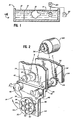
- FIGURE 1 is a diagrammatic view showing a typical ultrasonic inspection set-up;
- FIGURE 2 is a perspective view showing an array which is moved eccentrically in a circular path;
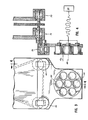
- FIGURE 3 is a front elevational view of an array which is moved eccentrically;
- FIGURE 4 is a sectional view taken substantially along line 4-4 of Figure 3;
- FIGURE 5 is a front elevational view of a transducer array which rotates as it is moved in a circular path;
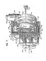
- FIGURE 6 is a sectional view taken along line 6-6 of Figure 5 showing the interior of the array assembly;
- FIGURE 7 is a perspective, partially elevational and partially sectional view of the array assembly of Figures 5 and 6;
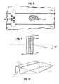
- FIGURE 8 is a diagrammatic view showing a linear movement;
- FIGURE 9 is a sectional view of a typical liquid crystal cell; and
- FIGURE 10 is a perspective view showing a shaped transducer.
- Referring now to Figure 1, there is shown a typical ultrasonic inspection apparatus 1.0 generally, which includes a
bath 12, usually water, within which atransducer 14, anobject 16, and liquidcrystal detector cell 18 are positioned and acoustically coupled. Thetransducer 14 insonifies theobject 16 and energy exiting the object is incident on thecell 18. The cell converts the incident energy to a visible image which can be seen by theviewer 19. Numerous optical systems can be provided for viewing the image and various different cell constructions can be used. For example, U.S. Patent No. 4,379,408 discloses a laminated type of liquid crystal detector cell. Thetransducer 14 may be an array or plurality of transducers which is moved by amotor 20. Both the motor and transducer obtain their power fromsource 22. - There are several embodiments of a movable transducer array which meet the criteria for a large and uniform insonifying beam. Specific embodiments are discussed in the following sections.
- It is to be noted that by moving the array, an insonifying beam cross-section is created which is larger than the stationary beam and the beam is more uniform since the movement provides an averaging effect. Averaging effect is intended to mean that each portion of the test area is insonified by acoustic energy of substantially the same intensity over an average period of time.
- One embodiment of a movable transducer array is shown in Figures 2, 3 and 4. Referring first to Figure 2, the
motor 20 and the movabletransducer array assembly 14 are shown. Themotor 20 is mounted to a fixed or stationary frame (not shown) as are thesupport plates rotatable shafts sprocket gear drive chain 36 is trained about the motor drive sprocket 38 and about the drivensprockets motor sprocket 38 drives thesprockets shafts - A pair of
links shafts links support plate 44 viabearings support member 44 includes a disc-shaped transducer carrier 50 in which seven sending or emittingtransducers - It will be appreciated that as the
motor 20 operates to rotate thesupport plate 44, the transducer faces move in substantially the same plane and the transducer axes all remains parallel to one another. In this arrangement, it can be said that the path of movement is substantially circular and caused by the eccentric movement of the drive and linkages. Furthermore, it is seen that the geometric center of the array which passes through the center oftransducer 64 is offset from the center of movement for the entire array. However, the center of movement is still within the periphery of the array itself, thus avoiding dead spots or uninsonified areas. - The parallel positioning of the axes of the transducers is seen in Figure 4 as is the offset between the geometric center of the transducers 68 and the axis of
rotation 70. Figure 4 shows a more detailed view of thebearings - From Figure 3 it will be appreciated that in this embodiment the transducers, such as 56 and 62, while they are in fact sweeping in a circular path, remain in the same vertical and horizontal or spatial relationship to each other.
- It will be appreciated by virtue of the construction herein that the
power source 22 can be connected directly to the transducer without twisting or damaging any of the connecting lines. - This embodiment produces a substantially uniform insonifying ultrasonic beam which is capable of insonifying large objects or sections of large objects. For example, a large graphite/epoxy panel was inspected with a beam having a 50-square inch area.
- Furthermore, depending upon the particular application, the transducer radiation axes can be at an angle, perhaps 10°, to the plane of array movement, so long as all axes are substantially parallel to each other. The embodiment described herein can be used with transducers where the axes are normal to the plane of movement or skewed relative to the plane of movement.
- Referring now to Figures 5, 6 and 7, a second embodiment for the movable transducer array is shown. In this embodiment there is again provided a
drive motor 20 which drives thechain 100 that is connected to a single drivensprocket 102. Thesprocket 102 is supported on ashaft 104 that is journalled and supported from astationary support plate 106. Theshaft 104 extends forwardly of thesupport plate 106 and carries aNeoprene seal 108,bushing 110, 24-tooth pinion gear 112, and terminates with abushing 114. Theplate 106 andshaft 104 provide a portion of a stationary section which includes thestationary back plate 116 and stationaryfront plate 118. Thepower source 22 is connected through a bushing-like structure 120 to acommutator assembly 121 which is also stationary. The commutator includes a pair of electrically conductingbrushes 121a and 121b. - The foregoing elements define a stationary structure which is fixed in place relative to the frame or tank which is being used. Those elements are shown in Figure 6 with diagonal lines extending from an upper left position to a lower right position and include
plate 106,plate 116,plates shaft 104 is maintained in position even though it is rotating within the stationary structure. - In order to rotate the transducers, the remaining portions of the transducer assembly array are rotatably carried on the stationary member. The rotatable portions include a cup-
like housing member 122 generally, which supports thetransducer array 124 generally. - As a general statement, the stationary portion remains in position and rotation of the
pinion gear 112 causes the cup-like member, and thus the transducer array, to rotate about an axis. In this situation the axis ofrotation 126 is spaced from the geometric center of thearray 128, and so long as the center ofrotation 126 is within the geometric periphery of the array, a substantially uniform or averaged beam will be provided. - Referring more specifically to the rotating member, the cup-
like member 122 includes a flatfront wall 130 and acylindrical side wall 132 which extends rearwardly therefrom and encloses portions of the stationary member. The rotary member is mounted to the stationary member by abearing 134 which is positioned between theside wall 132 and thestationary plate 118.Peripheral seals 136 are also provided to seal the interior of cup-shaped assembly. - A 96-
tooth ring gear 138 is mounted to the rotary member and is positioned for engagement by thepinion gear 112. A rotating commutator orslip ring assembly 140 is provided for electrical contact with thebrushes 121a and 121b. The slip ring is positioned adjacent the back edge of thefront plate 130. - Metal shielding members, such as 142 and 144, are provided about the slip ring assembly so as to suppress extraneous electrical signals due to the operation of the
commutator assembly 121. A copper-plateddisc 146 is supported from theassembly 140 for engagement by thebrushes 121a and 121b. - It will be appreciated that the
disc 146 rotates with the other rotatable elements, while the power line 120 remains stationary. Thus the operation of thebrushes 121a and 121b, along with the plateddisc 146, provide the connection for delivering electrical power to the transducers. As is seen, electrical connections may be made bylines - The
transducer array 126 is mounted to the front face of theplate 130 and carries seven sending or transmittingtransducers - In operation, the
motor 20 drives thechain 100, which in turn causes theshaft 104 andpinion gear 112 to rotate. Rotation of the pinion gear causes thehousing 122 to rotate due to the interaction of thepinion gear 112 andring gear 138. Power is continuously supplied to the transducers via line 120 which connects to thecommutator assembly 121, and in turn to theslip ring disc 146 and throughlines - The axis of rotation for the rotating portion of the housing is at the center of the ring gear which is indicated by the
axis 126. As the array is rotated in a circular path, the transducers also change their relative or spatial positions. This is unlike the first described embodiment. More specifically, thetransducer 162, which is shown at the 6 o'clock position in Figure 5, will move to the 9 o'clock position, and then the 12 o'clock position as shown by dotted lines in Figure 5. This is in a sense a planetary-type of movement. - In this embodiment the radiation axes are parallel to each other and normal to the plane or rotation.
- The speed of rotation for the arrays shown in Figures 2-4 and Figures 5-7 can be adjusted to fit individual conditions. Furthermore, while the hexagonal close-packed transducer arrangement is particularly useful for cylindrical or circular transducers, other arrangements may be used as can transducers having other shapes such as square or rectangular.
- In addition to the embodiments shown herein where the motion of the array is principally circular and about a predetermined centerline, it will be understood that a number of other motions along a closed path and which are periodic in nature can be used. For example, an elliptical motion could be produced, a square motion could be produced, and in both cases, the movement of the transducers is along a closed and predetermined path and is periodic in nature. In other words, there is a definable cycle to the movement of the transducers along whatever path is selected.
- In addition to the closed path, there can be movement along a predetermined path, such as a linear path or a curved path. For example, the transducers could be moved along a horizontal line from one extreme to a second extreme and then back. In Figure 8 an
array 200. of four square transducers can be moved back and forth along rails, such as 202 and 204, to scan theobject 206. Numerous of these types of paths can be defined depending upon the nature of the particular application. - It is anticipated that combinations of the arrays of Figures 2-4, 5-7 and 8 may be used. For example, a rotating array of the type in Figures 2-4 or 5-7 may be mounted on a carriage and moved linearly as in Figure 8. Moreover, arrays which spin about their own center axis may be suitable when the transducers are selected and arranged to avoid dead or uninsonified spots.
- In the embodiments shown in Figures 2-8, each array is shown employing a plurality of similar transducers. As shown, the transducers in each array are similar in size, shape, and operating characteristics. Depending upon the application, transducers of different sizes and shapes can be used in the same array. This necessarily means different operating characteristics. However, in all of the arrays the transmission frequency will be substantially the same. In addition, while the transducer radiation axes are parallel to each other, they may be either normal to or skewed relative to the plane of movement. If skewed, they must maintain the same angular relationship to the plane throughout the movement.
- In all of the embodiments, it is understood that a liquid crystal detector cell is positioned behind the object so as to receive ultrasonic radiation passing through the object.
- A typical liquid crystal cell is shown in Figure 9 and includes a pair of acoustically transparent cover plates or
substrates liquid crystal material 304, such as MBBA, is sealed between the covers by theperipheral seal 306. Specific details of such cells are disclosed in patents, such as U.S. Patent 4,379,408. These cells retain the image formed thereon for a period of time after the signal is removed. Thus the cell parameters, scanning speed of the moving transducers array, and angular relationship between the insonifying beam and cell need to be matched so as to assure a high-quality, continuous, non-flickering image. More specifically, image rise and decay times are used in selecting transducer scanning speeds. - Furthermore, the insonifying beam can strike the cell normal to its surface or within an angular range, which is dependent upon the cell constructions (e.g., il0") and provide a high-quality image. The particular acceptable angular variation is dependent on the particular cell and is selected to assure substantial acoustic transmission into the cell and through the cell substrates.
- Again, the angular relationship of the transducers to the cell must be matched in order to maximize performance. However, the axes of transmission of the individual transducers are maintained substantially parallel to each other.
- In all of the previously described embodiments, the angular relationship between the transducer radiation axes and the liquid crystal cell surface has remained constant and did not vary.
- Furthermore, single transducers may be used for scanning. For example, there is shown in Figure 10 a transducer where the beam forms a line that sweeps an object. Such a transducer is shown as 400, has a
concave face 402 and generates aline beam 404 that can sweep an object. Such a transducer can be moved linearly, as shown in Figure 8, and its movement timed to the cell construction. - Substantially uniform beams and images have been produced using embodiments discussed herein.
- It will be appreciated that numerous changes and modifications can be made to the embodiments described herein without departing from the spirit and scope of this invention.
Claims (12)
Priority Applications (1)
| Application Number | Priority Date | Filing Date | Title |
|---|---|---|---|
| AT84305012T ATE43016T1 (en) | 1983-07-25 | 1984-07-24 | MOBILE ULTRASONIC TRANSDUCER PANEL. |
Applications Claiming Priority (2)
| Application Number | Priority Date | Filing Date | Title |
|---|---|---|---|
| US06/516,542 US4530242A (en) | 1983-07-25 | 1983-07-25 | Movable ultrasonic transducer array |
| US516542 | 1983-07-25 |
Publications (3)
| Publication Number | Publication Date |
|---|---|
| EP0133007A2 true EP0133007A2 (en) | 1985-02-13 |
| EP0133007A3 EP0133007A3 (en) | 1985-11-06 |
| EP0133007B1 EP0133007B1 (en) | 1989-05-10 |
Family
ID=24056044
Family Applications (1)
| Application Number | Title | Priority Date | Filing Date |
|---|---|---|---|
| EP84305012A Expired EP0133007B1 (en) | 1983-07-25 | 1984-07-24 | Movable ultrasonic transducer array |
Country Status (9)
| Country | Link |
|---|---|
| US (1) | US4530242A (en) |
| EP (1) | EP0133007B1 (en) |
| JP (1) | JPS6085366A (en) |
| AT (1) | ATE43016T1 (en) |
| AU (1) | AU566357B2 (en) |
| CA (1) | CA1221447A (en) |
| DE (1) | DE3478147D1 (en) |
| IL (1) | IL72457A0 (en) |
| ZA (1) | ZA845671B (en) |
Cited By (2)
| Publication number | Priority date | Publication date | Assignee | Title |
|---|---|---|---|---|
| WO2010013175A1 (en) * | 2008-08-01 | 2010-02-04 | Koninklijke Philips Electronics, N.V. | Three dimensional imaging ultrasound probe |
| US10092270B2 (en) | 2007-09-17 | 2018-10-09 | Koninklijke Philips Electronics N.V. | Pre-collapsed CMUT with mechanical collapse retention |
Families Citing this family (9)
| Publication number | Priority date | Publication date | Assignee | Title |
|---|---|---|---|---|
| US4651567A (en) * | 1985-09-13 | 1987-03-24 | Raj Technology, Inc. | Non-coherent frequency source and sector scanning apparatus for ultrasonic imaging system using a liquid crystal detector cell |
| US4679436A (en) * | 1986-08-05 | 1987-07-14 | Raj Technology, Inc. | Reciprocating method and apparatus for producing uniform ultrasonic field for use in liquid crystal based acoustical imaging |
| US6137853A (en) * | 1994-10-13 | 2000-10-24 | General Electric Company | Method and apparatus for remote ultrasonic inspection of nozzles in vessel bottom head |
| US5796003A (en) * | 1996-01-30 | 1998-08-18 | Sandhu; Jaswinder S. | Acoustic imaging systems |
| US6049411A (en) * | 1998-10-14 | 2000-04-11 | Santec Systems Inc | Optical imager for birefringent detector acoustic imaging systems |
| US6321023B1 (en) | 2000-06-20 | 2001-11-20 | Honghui Wang | Serial imager for birefringent detector acoustic imaging systems |
| EP1798550B1 (en) | 2005-12-13 | 2018-07-25 | Lothgenoten B.V. | Device for inspecting the interior of a material |
| CA2554906C (en) * | 2006-05-10 | 2008-09-02 | Robert Allan Simmons | Method and apparatus for conveying an ultrasonic sensor about an outer peripheral surface of a tube |
| US20100152582A1 (en) * | 2008-06-13 | 2010-06-17 | Vytronus, Inc. | Handheld system and method for delivering energy to tissue |
Citations (5)
| Publication number | Priority date | Publication date | Assignee | Title |
|---|---|---|---|---|
| US3280621A (en) * | 1963-10-28 | 1966-10-25 | Louis C Cardinal | Omni-directional ultrasonic search unit |
| FR2112185A1 (en) * | 1970-07-27 | 1972-06-16 | American Express Invest | |
| FR2448829A1 (en) * | 1979-02-09 | 1980-09-05 | Litton Industrial Products | EXPLORATION APPARATUS AND METHOD FOR FORMING IMAGES BY ULTRASOUND |
| US4379408A (en) * | 1981-01-12 | 1983-04-12 | Raj Technology Partnership | Liquid crystal technique for examining internal structures |
| EP0101189A2 (en) * | 1982-07-20 | 1984-02-22 | Raj Technology Partnership | Non-destructive testing system employing a liquid crystal detector cell |
Family Cites Families (5)
| Publication number | Priority date | Publication date | Assignee | Title |
|---|---|---|---|---|
| US3837423A (en) * | 1970-10-29 | 1974-09-24 | Univ Ohio State Res Found | Acoustic excited liquid crystal image detector system |
| US3979711A (en) * | 1974-06-17 | 1976-09-07 | The Board Of Trustees Of Leland Stanford Junior University | Ultrasonic transducer array and imaging system |
| US4304133A (en) * | 1980-03-28 | 1981-12-08 | Feamster Iii William C | Positioning device for scanner |
| US4434659A (en) * | 1982-02-19 | 1984-03-06 | The United States Of America As Represented By The Administrator Of The National Aeronautics And Space Administration | Two-dimensional scanner apparatus |
| US4437468A (en) * | 1982-09-03 | 1984-03-20 | Medtronic, Inc. | Ultrasound scanning system with semi-independent transducer array |
-
1983
- 1983-07-25 US US06/516,542 patent/US4530242A/en not_active Expired - Fee Related
-
1984
- 1984-07-18 CA CA000459194A patent/CA1221447A/en not_active Expired
- 1984-07-20 IL IL72457A patent/IL72457A0/en unknown
- 1984-07-23 AU AU30942/84A patent/AU566357B2/en not_active Ceased
- 1984-07-23 ZA ZA845671A patent/ZA845671B/en unknown
- 1984-07-24 EP EP84305012A patent/EP0133007B1/en not_active Expired
- 1984-07-24 DE DE8484305012T patent/DE3478147D1/en not_active Expired
- 1984-07-24 AT AT84305012T patent/ATE43016T1/en not_active IP Right Cessation
- 1984-07-25 JP JP59155100A patent/JPS6085366A/en active Pending
Patent Citations (5)
| Publication number | Priority date | Publication date | Assignee | Title |
|---|---|---|---|---|
| US3280621A (en) * | 1963-10-28 | 1966-10-25 | Louis C Cardinal | Omni-directional ultrasonic search unit |
| FR2112185A1 (en) * | 1970-07-27 | 1972-06-16 | American Express Invest | |
| FR2448829A1 (en) * | 1979-02-09 | 1980-09-05 | Litton Industrial Products | EXPLORATION APPARATUS AND METHOD FOR FORMING IMAGES BY ULTRASOUND |
| US4379408A (en) * | 1981-01-12 | 1983-04-12 | Raj Technology Partnership | Liquid crystal technique for examining internal structures |
| EP0101189A2 (en) * | 1982-07-20 | 1984-02-22 | Raj Technology Partnership | Non-destructive testing system employing a liquid crystal detector cell |
Non-Patent Citations (1)
| Title |
|---|
| MOLECULAR CRYSTALS AND LIQUID CRYSTALS, LETTERS, vol. 45, no. 1/2, January/February 1978, London, GB; S. NAGAI et al. "Ultrasonic imaging utilizing a nematic liquid crystal", pages 83-101 * |
Cited By (6)
| Publication number | Priority date | Publication date | Assignee | Title |
|---|---|---|---|---|
| US10092270B2 (en) | 2007-09-17 | 2018-10-09 | Koninklijke Philips Electronics N.V. | Pre-collapsed CMUT with mechanical collapse retention |
| WO2010013175A1 (en) * | 2008-08-01 | 2010-02-04 | Koninklijke Philips Electronics, N.V. | Three dimensional imaging ultrasound probe |
| CN102112058A (en) * | 2008-08-01 | 2011-06-29 | 皇家飞利浦电子股份有限公司 | Three dimensional imaging ultrasound probe |
| US8475384B2 (en) | 2008-08-01 | 2013-07-02 | Koninklijke Philips Electroncis N.V. | Three dimensional imaging ultrasound probe |
| CN102112058B (en) * | 2008-08-01 | 2014-03-19 | 皇家飞利浦电子股份有限公司 | Three dimensional imaging ultrasound probe |
| RU2524190C2 (en) * | 2008-08-01 | 2014-07-27 | Конинклейке Филипс Электроникс Н.В. | Ultrasonic probe for obtaining three-dimensional image |
Also Published As
| Publication number | Publication date |
|---|---|
| ZA845671B (en) | 1985-03-27 |
| US4530242A (en) | 1985-07-23 |
| DE3478147D1 (en) | 1989-06-15 |
| JPS6085366A (en) | 1985-05-14 |
| IL72457A0 (en) | 1984-11-30 |
| EP0133007A3 (en) | 1985-11-06 |
| AU566357B2 (en) | 1987-10-15 |
| CA1221447A (en) | 1987-05-05 |
| AU3094284A (en) | 1985-01-31 |
| ATE43016T1 (en) | 1989-05-15 |
| EP0133007B1 (en) | 1989-05-10 |
Similar Documents
| Publication | Publication Date | Title |
|---|---|---|
| US4530242A (en) | Movable ultrasonic transducer array | |
| US4807476A (en) | Variable angle transducer system and apparatus for pulse echo inspection of laminated parts through a full radial arc | |
| US3023611A (en) | Ultrasonic method and apparatus for investigating the interior structure of solid bodies | |
| US4149419A (en) | Ultrasonic transducer probe | |
| US10605640B2 (en) | Apparatus and method for visualization of particles suspended in a fluid and fluid flow patterns using ultrasound | |
| US4404853A (en) | Method and apparatus for ultrasonic testing of tubular goods | |
| US7021143B2 (en) | Cylindrically-rotating ultrasonic phased array inspection method for resistance spot welds | |
| JP4582827B2 (en) | Ultrasonic diagnostic equipment | |
| US4238962A (en) | Transducer drive for ultrasonic imaging | |
| WO1992002180A1 (en) | Endoscopic probe | |
| US20040066708A1 (en) | Ultrasonic transmitting and receiving apparatus | |
| CA1193353A (en) | Ultrasonic imaging device | |
| GB1435531A (en) | Ultrasonic examination of an object | |
| US4426886A (en) | Ultrasonic scanner | |
| CA1251552A (en) | Non-coherent frequency source and sector scanning apparatus for ultrasonic imaging system using a liquid crystal detector cell | |
| US3845463A (en) | Ultrasonic testing apparatus | |
| US4346867A (en) | Transport mechanism for ultrasonic scanner | |
| JPS6321045A (en) | Mechanical scanning type ultrasonic probe | |
| GB1315712A (en) | Ultrasonic image-producing arrangement | |
| ES8801106A1 (en) | Ultrasonic compound scanning with a rotating transducer. | |
| CN211583235U (en) | Couplant applicator for ultrasound department | |
| JPS6336465B2 (en) | ||
| EP0174167A3 (en) | Ultrasonic transducers for medical diagnostic examination | |
| JPH01136638A (en) | Ultrasonic probe | |
| JPS6134811B2 (en) |
Legal Events
| Date | Code | Title | Description |
|---|---|---|---|
| PUAI | Public reference made under article 153(3) epc to a published international application that has entered the european phase |
Free format text: ORIGINAL CODE: 0009012 |
|
| AK | Designated contracting states |
Designated state(s): AT BE CH DE FR GB IT LI LU NL SE |
|
| PUAL | Search report despatched |
Free format text: ORIGINAL CODE: 0009013 |
|
| AK | Designated contracting states |
Designated state(s): AT BE CH DE FR GB IT LI LU NL SE |
|
| 17P | Request for examination filed |
Effective date: 19860421 |
|
| 17Q | First examination report despatched |
Effective date: 19871012 |
|
| GRAA | (expected) grant |
Free format text: ORIGINAL CODE: 0009210 |
|
| AK | Designated contracting states |
Kind code of ref document: B1 Designated state(s): AT BE CH DE FR GB IT LI LU NL SE |
|
| PG25 | Lapsed in a contracting state [announced via postgrant information from national office to epo] |
Ref country code: SE Effective date: 19890510 Ref country code: NL Effective date: 19890510 Ref country code: LI Effective date: 19890510 Ref country code: IT Free format text: LAPSE BECAUSE OF FAILURE TO SUBMIT A TRANSLATION OF THE DESCRIPTION OR TO PAY THE FEE WITHIN THE PRESCRIBED TIME-LIMIT;WARNING: LAPSES OF ITALIAN PATENTS WITH EFFECTIVE DATE BEFORE 2007 MAY HAVE OCCURRED AT ANY TIME BEFORE 2007. THE CORRECT EFFECTIVE DATE MAY BE DIFFERENT FROM THE ONE RECORDED. Effective date: 19890510 Ref country code: CH Effective date: 19890510 Ref country code: BE Effective date: 19890510 Ref country code: AT Effective date: 19890510 |
|
| REF | Corresponds to: |
Ref document number: 43016 Country of ref document: AT Date of ref document: 19890515 Kind code of ref document: T |
|
| REF | Corresponds to: |
Ref document number: 3478147 Country of ref document: DE Date of ref document: 19890615 |
|
| ET | Fr: translation filed | ||
| PG25 | Lapsed in a contracting state [announced via postgrant information from national office to epo] |
Ref country code: GB Effective date: 19890724 |
|
| PG25 | Lapsed in a contracting state [announced via postgrant information from national office to epo] |
Ref country code: LU Free format text: LAPSE BECAUSE OF NON-PAYMENT OF DUE FEES Effective date: 19890731 |
|
| REG | Reference to a national code |
Ref country code: CH Ref legal event code: PL |
|
| NLV1 | Nl: lapsed or annulled due to failure to fulfill the requirements of art. 29p and 29m of the patents act | ||
| GBPC | Gb: european patent ceased through non-payment of renewal fee | ||
| PLBE | No opposition filed within time limit |
Free format text: ORIGINAL CODE: 0009261 |
|
| STAA | Information on the status of an ep patent application or granted ep patent |
Free format text: STATUS: NO OPPOSITION FILED WITHIN TIME LIMIT |
|
| PG25 | Lapsed in a contracting state [announced via postgrant information from national office to epo] |
Ref country code: FR Free format text: LAPSE BECAUSE OF NON-PAYMENT OF DUE FEES Effective date: 19900330 |
|
| PG25 | Lapsed in a contracting state [announced via postgrant information from national office to epo] |
Ref country code: DE Effective date: 19900403 |
|
| 26N | No opposition filed | ||
| REG | Reference to a national code |
Ref country code: FR Ref legal event code: ST |