EP0132955A2 - Ophthalmic lens - Google Patents
Ophthalmic lens Download PDFInfo
- Publication number
- EP0132955A2 EP0132955A2 EP84304421A EP84304421A EP0132955A2 EP 0132955 A2 EP0132955 A2 EP 0132955A2 EP 84304421 A EP84304421 A EP 84304421A EP 84304421 A EP84304421 A EP 84304421A EP 0132955 A2 EP0132955 A2 EP 0132955A2
- Authority
- EP
- European Patent Office
- Prior art keywords
- lens
- function
- zone
- distance
- boundaries
- Prior art date
- Legal status (The legal status is an assumption and is not a legal conclusion. Google has not performed a legal analysis and makes no representation as to the accuracy of the status listed.)
- Granted
Links
Images


Classifications
-
- G—PHYSICS
- G02—OPTICS
- G02C—SPECTACLES; SUNGLASSES OR GOGGLES INSOFAR AS THEY HAVE THE SAME FEATURES AS SPECTACLES; CONTACT LENSES
- G02C7/00—Optical parts
- G02C7/02—Lenses; Lens systems ; Methods of designing lenses
- G02C7/06—Lenses; Lens systems ; Methods of designing lenses bifocal; multifocal ; progressive
- G02C7/061—Spectacle lenses with progressively varying focal power
-
- G—PHYSICS
- G02—OPTICS
- G02C—SPECTACLES; SUNGLASSES OR GOGGLES INSOFAR AS THEY HAVE THE SAME FEATURES AS SPECTACLES; CONTACT LENSES
- G02C7/00—Optical parts
- G02C7/02—Lenses; Lens systems ; Methods of designing lenses
- G02C7/024—Methods of designing ophthalmic lenses
-
- Y—GENERAL TAGGING OF NEW TECHNOLOGICAL DEVELOPMENTS; GENERAL TAGGING OF CROSS-SECTIONAL TECHNOLOGIES SPANNING OVER SEVERAL SECTIONS OF THE IPC; TECHNICAL SUBJECTS COVERED BY FORMER USPC CROSS-REFERENCE ART COLLECTIONS [XRACs] AND DIGESTS
- Y10—TECHNICAL SUBJECTS COVERED BY FORMER USPC
- Y10S—TECHNICAL SUBJECTS COVERED BY FORMER USPC CROSS-REFERENCE ART COLLECTIONS [XRACs] AND DIGESTS
- Y10S425/00—Plastic article or earthenware shaping or treating: apparatus
- Y10S425/808—Lens mold
Definitions
- This invention is related to ophthalmic lenses and, in particular to a novel progressive power and multifocal ophthalmic lens in which a surface of the lens has distance, near and intermediate viewing zones with boundaries and contours which provide desired optical properties over the surface of the lens.
- the invention also comprehends methods of making lenses with these properties while providing flexibility in the selection of wearer-adapted parameters, and shaped formers used in the manufacture of such lenses.
- the direct ancestor of the progressive multifocal lens is the bifocal lens which consists of a distance viewing zone of one optical power and a near viewing zone of another optical power, located adjacent the distance zone.
- Each zone may have a convex spherical surface with an abrupt change in curvature at a boundary where the zones abut.
- These lenses have the disadvantage that they are limited to two, more or less fixed optical powers. The change in power at the zone boundary can produce undesirable optical effects for the wearer. In addition, the zone boundaries are sometimes considered unattractive when the lens is viewed on the wearer.
- the intermediate zone should join the near and distance zones in a cosmetically acceptable way, in the sense that no discontinuities in the lens should be visible to people observing the lens on the wearer.
- the intermediate zone should be optically acceptable in the sense that there sould be a line or corridor, called the eye path, along which the line of vision moves while going between the distance and near zones and along which the optical power of the lens increases more or less uniformly.
- the quality of vision along the eye path should be as good as possible to permit some intermediate viewing through the intermediate zone and to provide a comfortable transition in powers for the eye between the near and distance zone. This result is furthered by minimizing or removing astigmatism along the eye path. It is possible to select an eye path with a slant to accommodate the natural convergence of the eyes. It may also be desirable to select particular shapes for the zones.
- Finished progressive lenses are typically made from progressive lens blanks, i.e. optical bodies having a finished convex front progressive surface and an unfinished rear concave surface. The rear surface is normally finished to produce a lens which meets the wearer's prescription.
- progressive lens blanks i.e. optical bodies having a finished convex front progressive surface and an unfinished rear concave surface. The rear surface is normally finished to produce a lens which meets the wearer's prescription.
- a family of progressive lens blanks with different distance and near zone powers shoudl be available. In such a family, each blank will incorporate a similar selection and/or optimization of some or all of the above-mentioned basic design characteristics. Such a consistency is an aid in the designing, manufacturing, testing and prescribing of the lenses.
- lens refers to all forms of refractive optical bodies employed in the ophthalmic arts, including, but not limited to, semi-finished lens blanks requiring further finishing to a particular patient's prescription. Also included are formers used in the manufacture of progressive glass lenses, and molds for the casting of progressive lenses in polymeric material such as the material sold under the trade name CR 39.
- the invention provides an ophthalmic lens with a lens surface having a near viewing zone, a distance viewing zone and an intermediate zone in which there is a gradual change in optical power along an eye path from the distance zone to the near zone, characterised in that boundaries defined between the distance zone and the intermediate zone, and between the intermediate zone and near zone are projections of algebraic curves on the lens surface;
- the shape of the surface of the lens is defined by a final surface function such that the surfaces of the zones are the same height at the boundaries and so that at least the first three derivatives of the final surface function are continuous across the boundaries;
- a preliminary polynominal function is derived in the coordinate system (u, v) such that the preliminary function defines a surface for the intermediate zone so that the surfaces of the zones are the same height at zone boundaries and so that at least the first two partial derivatives of the surface function with respect to v are the same at the boundaries.
- the polynomial function may be of low degree, for example, 8th degree in u and 7th degree in v.
- the cartesian coordinates x and y may be translatable in polynomials of the second degree in u and v.
- Auxiliary functions may be chosen to modify the optical properties of the lens in certain selected areas of the lens.
- a mathematical product may be obtained by multiplying the preliminary function and the auxiliary function in the intermediate zone.
- the auxiliary function may be multiplied with the add surface function in the near zone to produce a second product.
- the . base surface function may then be added to the products in the respective zones to provide a final surface function defining the surface of the near zone and intermediate zone.
- the forming may be accomplished by sag molding a glass blank on a machined porous former configured in accordance with the final surface function.
- the selection of functions may be repeated in an iterative fashion while varying one or more of the lens parameters and evaluating the resultant mathematical function or the lens itself for desirable properties including reduction of astigmatism and distortion.
- the shape of the surface of the lens may be defined by a final surface function selected so that the surfaces of the zone are the same height at the boundaries and so that at least the first three derivatives of the final surface are continuous across the boundaries.
- the final surface function and coordinate system transformation may be defined by polynomial functions as discussed above.
- a preliminary function may be obtained defining the progressive surface.
- the surface may then be evaluated (e.g. for power, astigmatism, orthoscopy) and zone boundary geometry parameters modified in an iterative fashion.
- the final surface function may be a function which is product of a preliminary function and at least one auxiliary function, wherein the preliminary and auxiliary functions are both continuous to at least the third derivative along the boundaries of the zones.
- the auxiliary function may be selected to improve orthoscopy in at least a portion of the intermediate zone.
- orthoscopy is intended to refer to the rectangularity of images of vertically oriented rectangular objects observed through the lens.
- An auxiliary function may be selected to reduce astigmatism in at least a portion of the intermediate zone.
- astigmatism refers to surface astigmatism, which is a measure of the degree to which the curvature of the lens varies along intersecting planes which are normal to the surface of the lens at a point on the surface.
- auxiliary functions may be employed.
- the preliminary function may be multiplied with auxiliary function(s), the resulting surface or surface function evaluated, and the auxiliary function(s) modified in an iterative fashion to reduce astigmatism and/or improve orthoscopy in selected regions of the lens, while retaining desirable properties of the preliminary function in other area of the lens.
- a progressive ophthalmic lens, made according to the present invention is shown in Figure 1.
- The: lens may be divided into three zones.
- the top, or distance, zone 10 is intended to provide the user with conventional distance correction substantially unimpaired by any effects from the special optical zones below.
- the bottom, or near zone 12 should likewise provide good vision with increased positive power for near vision tasks, as in a conventional bifocal.
- a central, or intermediate zone 14 lies between the distance and near zones.
- a first boundary 16 lies at the meeting of the distance and intermediate zone, and a second boundary 18 lies at the meeting of the intermediate and near zones.
- the boundaries may be diffuse or sharp. The significance of the boundaries to the design of the lens will be discussed below.
- the intermediate zone 14 is intended to join the distance and near zones in a way that is cosmetically acceptable in the sense that no discontinuities are apparent to persons viewing the lens on the wearer.
- the transition is optically acceptable, in the sense that there is a narrow corridor or eye path 20, along which the line of vision moves while going between the distance and near zones, and along which the optical power preferably increases more or less uniformly from that of the distance zone to that of the near zone.
- the quality of vision along this eye path should be as good as possible so that the wearer will experience a minimum of discomfort as his gaze moves back and forth between distance and near zones. As a practical matter this gives rise to a need to correct astigmatism as well as possible along the eye path.
- the present design provides acceptably small astigmatism (i.e., less than .5 diopter) along the eye path, without requiring it as an explicit design limitation.
- the eye path should deviate from a vertical centerline of the lens as shown in Figure 3, in order to accomodate the natural convergence of the eyes as they move from distance to near vision.
- the boundaries 16 and 18 may be curved so as to allow the joining of the zones over a great distance and over a large part of the lens.. This may also help to limit aberrations in the intermediate zone.
- a usable solution can be obtained ignoring any effects of the obliquity with which rays may strike the optical surfaces of the system and ignoring any higher order effects of variations in the thickness of the lens.
- a usable solution can be obtained by representing all surface curvatures by means of simple second order partial derivatives, ignoring the nonlinear first derivative tilt factors.
- the curvilinear coordinate system (u,v) has been devised to allow designation of the boundaries between the principal regions of the lens by curves of the form v * constant, where v is the new coordinate corresponding most nearly to the vertical cartesian coordinate y. Curves 16 and 18 of Figure 1 are examples of such curves.
- the line 20 of Figure B represents such an eye path.
- the coordinate system developed is one in which x and y are polynomial functions of the new coordinates u and v and where these polynomials are of the minimum degree consistent with the desired qualitative properties of the coordinate system.
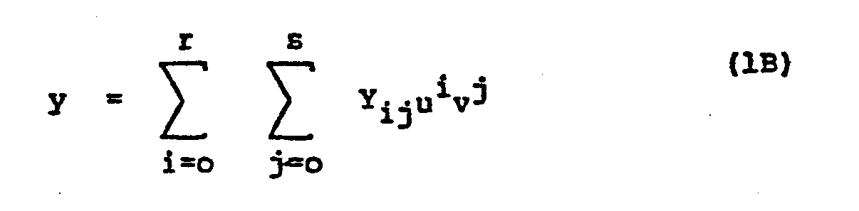
- x and y are to be expressed in the form: where Xij and Yij are coefficients, ui and vj are the coordinates of the curvilinear coordinate system, raised to the ith and jth power, respectively; p and q are the degrees of u and v for definition of x, respectively, and r and s are the degrees of u and v for definition of y.
- the selection of the parameters p,q,r and s are preferably kept as small as possible, and are equal to two or less in the preferred embodiments discussed below.
- the desired general shape of the u and v coordinate curves are shown in Figure 1.
- the curves v constant, are seen to be parabola-like curves.
- u o is the initial guess for u.
- a careful examination of f(u) has shown that this guess will always guarantee convergence of the iteration as long as the inverse transformation is single valued (and therefore meaningful in this context). This follows from the fact that all roots can be shown to lie to the left of u o , that u o can never lie between the local extrema of f(u) (if any exist) and that the value of f(u) at its inflection point is positive when extrema exist.
- the inverse transformation is believed to be always single-valued over the usable lens surface, but singularities (non-invertibilities) may exist just off the lens.
- the iteration may proceed.
- the derivative of f(u) is computed: where-f'(u) is the derivative of f(u) with respect to u.
- Improved quesses for u are then made by iteration using Newton's method: where un is the current guess and un+l is the next guess.
- the initial guess is given by u o above.
- the iteration is halted when the change in u from one stage to the next is less than some predetermined value, say, 1 micron.
- the resulting final value of u is then taken as the value determined by the given values of x and y, and the corresponding value of v is computed by solving the transformation equation (2B) for v:
- the results may be checked by back substitution into the coordinate transformations (2).
- the computed values of u and v should give back the originally given values of x and y.
- the total surface height or final surface function Z t may be defined as the sum of two terms: where Zd is the surface function of the distance zone and Z is the deviation or progressive addition function.
- Zd is the surface function of the distance zone
- Z is the deviation or progressive addition function.
- Figure 3 The general relationship of these functions is shown in Figure 3, in which the line Z t corresponds to a cross-section of the surface of the lens along a plane containing the y axis and perpendicular to the x axis.
- the distance zone surface function Z d may be selected as a rotationally symmetric surface.
- the useful case of a spherical surface function Z a will now be considered.
- Such a function may be defined by an equation of the form where R d is the radius of curvature of the distance region prescribed for correction of distance viewfng; and ⁇ x and ⁇ are offsets of the vertex of the sphere to permit decentration of the sphere as desired.
- the progressive function Z may be defined piecewise to reflect the different optical properties of the different lens regions as follows: wherein Aij are coefficients to be determined from the optical specifications of the intermediate zone, M and N are the degrees of u and v, respectively, in the intermediate zone, and Z s is a near zone add function (a quartic surface of revolution) to be discussed below.
- the degrees M and N are to be kept as small as possible consistant with the optical specifications for the intermediate zone. In the embodiment of the invention discussed below M is equal to 8 and N is equal to 7.
- U(u) and S(y) are auxiliary functions selected to help control astigmatism and orthoscopy in portions of the transition zone.
- Z s is a near zone add function which is intended to have optical performance similar to a sphere to achieve the prescribed correction of near vision.
- a surface of revolution may be choosen of the following form: where A is a coefficient specifying the near zone curvature and thus its optical power; B s is a coefficient to allow for correction of the near zone to approximately a spherical shape x o and y o are the cartesian coordinates of the vertex (relative optical center) of the near zone; and z o is an additive constant to provide for surface height matching.
- A is a coefficient specifying the near zone curvature and thus its optical power
- B s is a coefficient to allow for correction of the near zone to approximately a spherical shape
- x o and y o are the cartesian coordinates of the vertex (relative optical center) of the near zone
- z o is an additive constant to provide for surface height matching.
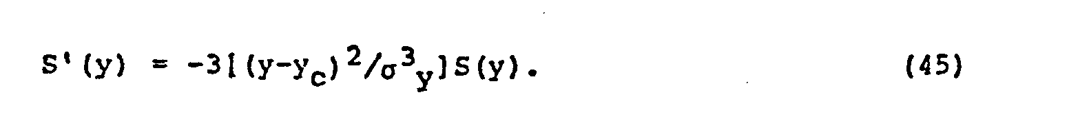
- auxiliary functions S(y) and U(u) which are applied to modify the preliminary surface function in selected regions.
- the auxiliary function S(y) may be defined as: where the parameter ay determines the "strength" of the function and y c determines the boundary of the selected region.
- the auxiliary function U(u) may be defined by: where ° u defines the "strength" of the u auxiliary function. It will be understood that other expressions which are continuous through the third derivatives, may be employed as auxilliary functions. The use and effect of the auxiliary functions will be discussed in greater detail below.
- boundary conditions can be expressed mathematically as:
- the degree of this last polynomial can be inferred by noting that it is the result of substituting the transformation equations (2nd degree in u) into the defining expression for Z s (4th degree in x and y) resulting in a final expression of the 8th degree in u.
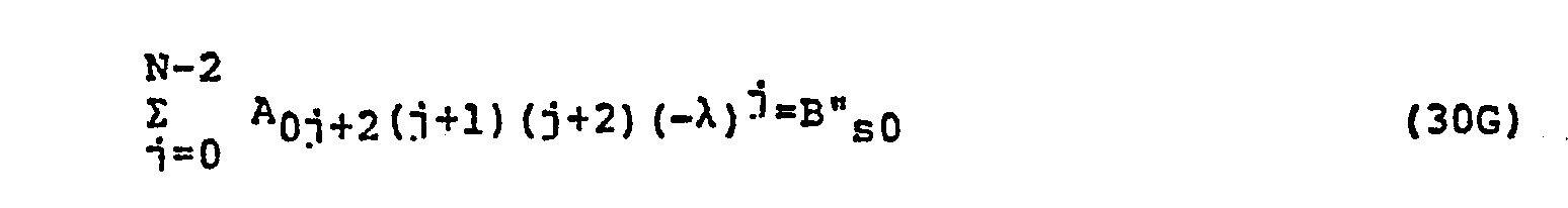
- B si 's to solve for. B sa is found as shown in section IV below.
- the rest are computed by evaluating the polynomial at eight points along the boundary, subtracting 8 s0 from each value, and then solving numerically the system of eight linear equations resulting from the requirement that the polynomial take on the computed values at the given points.
- the same is done using the partial derivative Zsv instead of Z s to obtain the B' s i's, etc.
- the eye path specification consists in preselecting the values of the A 0j 's.
- the selection may conveniently use either a cubic or quintic eye path.
- a cubic eye path the power changes linearly.
- a quintic eye path the power changes gradually and has a maximum rate of change near the midpoint of the eye path. In the quintic case, rate of change of power can be made continuous.
- a cubic eye path is used for second derivative boundary matching and a quintic eye path for third derivative boundary matching. Since the preferred embodiment thus far discussed requires third derivative boundary matching, the quintic eye path will be employed.
- B s0 , etc. are determined from the near zone surface function Z s , we see that they are functions of x o . Y o , and z o . Since the latter are among the quantities to be determined, the system contains a total of four equations in seven unknowns. We thus have an underdetermined system of equations.
- A06 and A07 we first arbitrarily set to zero. This gives an eye path shape of minimum degree, which is an arbitrary choice and others are possible. Other such choices might be used, e.g. to permit improved eye-path astigmatism or a modified eye-path power contour. However, the low astigmatism and satisfactory power contour obtained with A 06 and A 07 set equal to zero suggest that little is to be gained by such a procedure.
- x o In order to reduce the total number of unknowns to four, as discussed above, a value of x o can be selected.
- the selection need not be arbitrary, since x o is the x coordinate of the near zone function center and we may anticipate the effects of positioning of the near zone function to affect the lens performance. For example, when designing decentered lenses it has not been surprising to find that x o must be offset somewhat for best performance. The designer will generally need to try a range of values of x o , for example, to give a reasonably symmetric astigmatism pattern on either side of the near zone. Such a value would be expected to be between zero and the amount of decentration of the near zone. Once this value has been specified there remain only four unknowns to be solved for: A04, A 05 , y o , and z o . The four equations for these unknowns may now be written:
- B s0 contains the unknowns yo and zo, but the other three right hand sides contain only y o ⁇
- the last three equations may be taken as three equations for the three unknowns A04, A 05 . and y o . Because, y o is involved non-linearly on the right, it is convenient to solve the last three equations iteratively.
- A04 and A 05 may be computed by the formulas (33) above.
- the procedure begins by evaluating the optical performance (astigmatism and mean power.variation) in the near zone when the above estimates are used for As and B s .
- the power and astigmatism should be checked at the nominal measurement point (e.g. 14 mm. below geometrical center) and at at least two additional points further down in the near zone. If, for example, the astigmatism axis in the lower near zone is at or near 90 degrees then the power there is stronger in the transverse direction than in the vertical direction.
- Astigmatism axis indicates the angular direction of the normal plane in which the curvature is greatest, the y axis corresponding to an angle of 90°, the angle increasing in a counterclockwise direction).
- B s must be increased, since the vertical power will generally be much more sensitive to the value of B s than the transverse power. By repeating the procedure as necessary, acceptable vertical and transverse power matching can be obtained.
- the power variation along the near zone center line should be checked. If, for example, the power is found to drop off as one moves down the near zone, then the values of both As and B s will have to be adjusted. In this case As should be decreased slightly and B s increased to bring the power at the measurement reference point (14 mm.
- a final surface function may be generated by evaluation of the polynomial formula on a grid of points, multiplication by the auxiliary functions and addition to the base surface function.
- the final surface function is progenitive of a lens formed as discussed below.
- An array of surface heights from the x,y plane are presented in Figure 4 for the progressive surface of Table I.
- the partial derivatives necessary to compute the normal vector can be computed from the explicit form of z t . Recall This implies and where Z dx etc. are partial derivatives.
- the choice of a final surface function as the simple sum of a distance sphere and an add function has this important benefit: it permits simple computation of the partial derivatives needed to compute the normal.
- the partial derivatives of the distance sphere Z d (defined in eq. (21)) with respect to x and y are: As before, these must be added to Z x and Z y, computed below, to obtain the total surface height derivatives Zt x and Zty. The partial derivatives of Z are now obtained. In the distance zone this is trivial since Z is defined to be zero there, and so all of its derivatives are also zero.
- the procedure is the same, except that derivatives of the near zone function Z s are required.
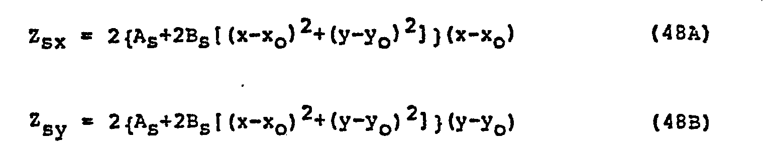
- Those derivatives are as follows: The derivatives of Z in the near zone are computed identically to those in the intermediate zone, but with Z s , Z sx , Z s y substituted for Zp, Z px , Zpy respectively..
- the normal vector can be calculated in a conventional manner, and the calculated normal vector used to position a cutting head used in the manufacturing processes discussed below.
- the astigmatism and mean power of a progressive surface such as that indicated in Figure 4 can be predicted.
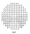
- the iesults of these predictions are shown in Figures 5 and 6 for an array of points corresponding to the points of Figure 4.
- the numerical values indicate the magnitude of the astigmatism - and the directions of the line segments indicate the directions of the astigmatism axis.
- Astigmatism diagrams of the type of Figures 5 are useful in evaluating lens designs.
- the progressive surface presented in the Figures has a large window of nearly zero astigmatism (.5 diopters or less) corresponding to the distance zone.
- astigmatism is minimized in the near zone and in a wide corridor centered on the eye path.
- low levels . of astigmatism are achieved in other areas of the intermediate zone.
- the manufacture of progressive lenses is carried out by using the final surface function derived above to provide height values for a multiplicity of points, e.g., at 1 millimeter centers, and then, by means of a numerically controlled milling machine, producing a porous ceramic former with a surface configured to correspond to the aformentioned height values. It is usually unnecessary to generate the height values outside the milling machine system because such machines often have associated computers which can solve the necessary expressions and then carry out the evaluations for each point once fed the parameters of the final surface function.
- the porous ceramic former thus prepared, can then be used in a conventional manner to form a progressive surface of a glass lens or lens blank by sag forming techniques.
- the porous former can also be used to form a mold part, which can then be used to form the progressive surface in a cast lens in a conventional lens casting process. Techniques of using such formers are described in, for example, United States Patent No. 4,062,629 to winthrop (see columns 14 and 19.)
- Power and astigmatism diagrams may then be generated for the near zone, for example, by conventional methods such as a computer ray trace. These diagrams may. then be used to evaluate the near zone surface. Such evaluation may include determining whether the near zone add power is correct, and determining whether the departures of the near zone from sphericity are acceptable.
- the boundary geometry parameters are selected: i . e ., w s , y s , ⁇ s ,w d , Y d , ⁇ d and p . From this information the preliminary A ij 's may be calculated. In turn, the preliminary intermediate zone function Z p may be calculated. As before, power and astigmatism diagrams may be generated in the conventional manner, which permit evaluation of the intermediate zone surface. As described above, the surface may be evaluated and, if necessary, changes made in the boundary geometry parameters originally selected; and the procedure repeated until an acceptable intermediate zone surface is obtained. At this point the location of the vertex of the distance sphere may be determined, and repositioned as necessary by adjustments in the values ⁇ x and ⁇ y . Such a readjustment may require a return to the first step, in exceptional circumstances.
- the final surface function is then supplied to a numerically controlled milling machine for the machining of a porous ceramic former.
- the porous ceramic former may be either concave or convex in configuration depending on the particular process employed in producing the final lens.
- Figure 8 illustrates in cross-pection the formation of a glass lens blank 100 on a ceramic porous former 102.
- a surface of the ceramic former 102 is exposed to a vacuum indicated schematically by the arrow 104.
- a polished glass blank typically of uniform thickness, is placed on top of the former 102 and the assembly placed inside an oven capable of raising the temperature of the blank 100 to above the softening point of the glass. It will be understood that the effects of the temperature and vacuum will be such to cause the lens blank to conform to the shape of the former 102.
- the upper surface 105 of the formed blank 100 will be a replica of the progressive surface of the porous former, it being understood that the smoothness of this surface will not be compromised during the formation process.
- FIG 10 a process for molding a plastic lens is illustrated.
- a glass mold blank 106 is sagged into a concave porous former 108 similar to the former described in connection with Figure 8.
- the progressive mold part 106 is then located in spaced relationship to a generally spherically curved glass mold part 110.
- the two mold parts are placed in contact with a gasket 112 and held in spaced relation to one another.
- Liquid resin is introduced into the mold and the resin is cured.
- the semi-finished lens blank is removed from the mold assembly after cure.
Abstract
Description
- This invention is related to ophthalmic lenses and, in particular to a novel progressive power and multifocal ophthalmic lens in which a surface of the lens has distance, near and intermediate viewing zones with boundaries and contours which provide desired optical properties over the surface of the lens. The invention also comprehends methods of making lenses with these properties while providing flexibility in the selection of wearer-adapted parameters, and shaped formers used in the manufacture of such lenses.
- The direct ancestor of the progressive multifocal lens is the bifocal lens which consists of a distance viewing zone of one optical power and a near viewing zone of another optical power, located adjacent the distance zone. Each zone may have a convex spherical surface with an abrupt change in curvature at a boundary where the zones abut. These lenses have the disadvantage that they are limited to two, more or less fixed optical powers. The change in power at the zone boundary can produce undesirable optical effects for the wearer. In addition, the zone boundaries are sometimes considered unattractive when the lens is viewed on the wearer.
- Over the last 70 or 80 years attempts have been made to achieve a progressive increase in optical power from a distance viewing part of a lens to a near reading part of the lens. In so doing astigmatism and distortion are necessarily introduced into the lens.
- Certain characteristics in the progressive lens are desirable. The intermediate zone should join the near and distance zones in a cosmetically acceptable way, in the sense that no discontinuities in the lens should be visible to people observing the lens on the wearer. The intermediate zone should be optically acceptable in the sense that there sould be a line or corridor, called the eye path, along which the line of vision moves while going between the distance and near zones and along which the optical power of the lens increases more or less uniformly. The quality of vision along the eye path should be as good as possible to permit some intermediate viewing through the intermediate zone and to provide a comfortable transition in powers for the eye between the near and distance zone. This result is furthered by minimizing or removing astigmatism along the eye path. It is possible to select an eye path with a slant to accommodate the natural convergence of the eyes. It may also be desirable to select particular shapes for the zones.
- In order to understand problems associated with the provision of these desirable lens characteristics, it is helpful to understand how such lenses are made and dispensed. Finished progressive lenses are typically made from progressive lens blanks, i.e. optical bodies having a finished convex front progressive surface and an unfinished rear concave surface. The rear surface is normally finished to produce a lens which meets the wearer's prescription. However, to provide a range of distance and near zone optical powers which permit optimum fitting of the lens to most presbyopic patients, a family of progressive lens blanks with different distance and near zone powers shoudl be available. In such a family, each blank will incorporate a similar selection and/or optimization of some or all of the above-mentioned basic design characteristics. Such a consistency is an aid in the designing, manufacturing, testing and prescribing of the lenses.
- However, it is not a simple matter to choose an appropriate generalized expression to describe the progressive properties of a family of lens blanks. Such an expression needs to be one which readily permits alteration of distance zone power and near zone power, to obtain the desired specific characteristics of one of the family of lens blanks. In addition the design techniques, should, advantageously permit generation of different families of lenses, embodying different selections of other parameters such as zone size and placement, eye path location, etc.
- It is an object of the present invention to provide a method for making lenses in which design parameters may be easily manipulated to produce progressive lenses having varying ophthalmic properties, that is the optical power, shape, size and/or location of the distance or near zones may be easily modified from lens to lens, and in which astigmatism and distortion are selectively distributed to improve optical and/or cosmetic properties of the lens.
- The invention also provides progressive lenses and progressive lens families with a large distance viewing zone, a large near viewing zone, a wide eye path corridor, and little or no astigmatism along the eye path.
- As used herein the word "lens" refers to all forms of refractive optical bodies employed in the ophthalmic arts, including, but not limited to, semi-finished lens blanks requiring further finishing to a particular patient's prescription. Also included are formers used in the manufacture of progressive glass lenses, and molds for the casting of progressive lenses in polymeric material such as the material sold under the trade name CR 39.
- The invention provides an ophthalmic lens with a lens surface having a near viewing zone, a distance viewing zone and an intermediate zone in which there is a gradual change in optical power along an eye path from the distance zone to the near zone, characterised in that boundaries defined between the distance zone and the intermediate zone, and between the intermediate zone and near zone are projections of algebraic curves on the lens surface; the shape of the surface of the lens is defined by a final surface function such that the surfaces of the zones are the same height at the boundaries and so that at least the first three derivatives of the final surface function are continuous across the boundaries; and the surface of the near zone is defined by an equation of the form ZT=Zd+Zs where ZT is the final function, Zd is the rotationally symmetric surface function of the distance zone extended over the entire lens, and Zs is a near zone surface function having a factor given by a fourth degree expression in the cartesian coordinates x and y.
- Preferably in carrying out the method of the invention a preliminary polynominal function is derived in the coordinate system (u, v) such that the preliminary function defines a surface for the intermediate zone so that the surfaces of the zones are the same height at zone boundaries and so that at least the first two partial derivatives of the surface function with respect to v are the same at the boundaries. The polynomial function may be of low degree, for example, 8th degree in u and 7th degree in v. The cartesian coordinates x and y may be translatable in polynomials of the second degree in u and v.
- Auxiliary functions may be chosen to modify the optical properties of the lens in certain selected areas of the lens. A mathematical product may be obtained by multiplying the preliminary function and the auxiliary function in the intermediate zone. Similarly, the auxiliary function may be multiplied with the add surface function in the near zone to produce a second product. The . base surface function may then be added to the products in the respective zones to provide a final surface function defining the surface of the near zone and intermediate zone.
- The forming may be accomplished by sag molding a glass blank on a machined porous former configured in accordance with the final surface function.
- The selection of functions may be repeated in an iterative fashion while varying one or more of the lens parameters and evaluating the resultant mathematical function or the lens itself for desirable properties including reduction of astigmatism and distortion.
- The shape of the surface of the lens may be defined by a final surface function selected so that the surfaces of the zone are the same height at the boundaries and so that at least the first three derivatives of the final surface are continuous across the boundaries. The final surface function and coordinate system transformation may be defined by polynomial functions as discussed above.
- A preliminary function may be obtained defining the progressive surface. The surface may then be evaluated (e.g. for power, astigmatism, orthoscopy) and zone boundary geometry parameters modified in an iterative fashion.
- The final surface function may be a function which is product of a preliminary function and at least one auxiliary function, wherein the preliminary and auxiliary functions are both continuous to at least the third derivative along the boundaries of the zones. The auxiliary function may be selected to improve orthoscopy in at least a portion of the intermediate zone. As used herein "orthoscopy" is intended to refer to the rectangularity of images of vertically oriented rectangular objects observed through the lens. An auxiliary function may be selected to reduce astigmatism in at least a portion of the intermediate zone. As used herein the word "astigmatism" refers to surface astigmatism, which is a measure of the degree to which the curvature of the lens varies along intersecting planes which are normal to the surface of the lens at a point on the surface. Both types of auxiliary functions may be employed. The preliminary function may be multiplied with auxiliary function(s), the resulting surface or surface function evaluated, and the auxiliary function(s) modified in an iterative fashion to reduce astigmatism and/or improve orthoscopy in selected regions of the lens, while retaining desirable properties of the preliminary function in other area of the lens.
- Some embodiments of the invention are described in detail below, by way of example, with reference to the accompanying drawings in which:
- Figure 1 is a front elevation of a progressive ophthalmic lens according to the invention illustrating a coordinate system used to define a surface of the lens,
- Figure 2 is a front elevation of another progressive ophthalmic lens according to the present invention illustrating parameters used in the design of the lens,
- Figure 3 is a cross-sectional profile of a progressive surface of an ophthalmic lens of the present invention,
- Figure 4 is an array of calculated values related to surface heights for a particular progressive surface of a lens according to the invention,
- Figure 5 is an array of calculated values of the astigmatism of the progressive surface of Figure 4,
- Figure 6 is an array of calculated values of the mean power of the progressive surface of Figure 4,
- Figure 7 is a flow diagram illustrating steps of a method according to the invention for making a cast ophthalmic lens,
- Figure 8 is a cross-sectional view of the formation of a glass lens blank on a ceramic former,
- Figure 9 illustrates compensation for deviations in the formation of the glass lens blank, and
- Figure 10 illustrates a process for molding a plastic lens blank.
- A progressive ophthalmic lens, made according to the present invention is shown in Figure 1. The: lens may be divided into three zones. The top, or distance,
zone 10 is intended to provide the user with conventional distance correction substantially unimpaired by any effects from the special optical zones below. The bottom, or nearzone 12 should likewise provide good vision with increased positive power for near vision tasks, as in a conventional bifocal. A central, orintermediate zone 14 lies between the distance and near zones. Afirst boundary 16 lies at the meeting of the distance and intermediate zone, and asecond boundary 18 lies at the meeting of the intermediate and near zones. The boundaries may be diffuse or sharp. The significance of the boundaries to the design of the lens will be discussed below. - The
intermediate zone 14 is intended to join the distance and near zones in a way that is cosmetically acceptable in the sense that no discontinuities are apparent to persons viewing the lens on the wearer. The transition is optically acceptable, in the sense that there is a narrow corridor oreye path 20, along which the line of vision moves while going between the distance and near zones, and along which the optical power preferably increases more or less uniformly from that of the distance zone to that of the near zone. Desirably, the quality of vision along this eye path should be as good as possible so that the wearer will experience a minimum of discomfort as his gaze moves back and forth between distance and near zones. As a practical matter this gives rise to a need to correct astigmatism as well as possible along the eye path. The present design provides acceptably small astigmatism (i.e., less than .5 diopter) along the eye path, without requiring it as an explicit design limitation. - The eye path should deviate from a vertical centerline of the lens as shown in Figure 3, in order to accomodate the natural convergence of the eyes as they move from distance to near vision. In addition, the
boundaries - In order to meet these several requirements simultaneously and in order to permit selective changes in one or more design parameters, a novel coordinate system has been devised. In this coordinate system the special curves of the problem - the interzone boundaries and the eye path - are represented in a simple way, as curves along which one or another of the coordinates takes on a constant value. Relatively simple coordinate transformations, connecting this new system with ordinary cartesian coordinates, have been devised to define the lens structure. Polynomial functions are used as base functions to describe the optical surface and the coordinate system. Boundary conditions are imposed which produce equations in the coefficients of the polynomials which can be solved to provide a final surface function for the lens.
- In making the lens, two additional assumptions may also be made. First, it may be assumed that a usable solution can be obtained ignoring any effects of the obliquity with which rays may strike the optical surfaces of the system and ignoring any higher order effects of variations in the thickness of the lens. Second, it is assumed that a usable solution can be obtained by representing all surface curvatures by means of simple second order partial derivatives, ignoring the nonlinear first derivative tilt factors.
- 'These initial simplifications have been found not to stand in the way of good optical correction of a finished design. The simple system as described above may be used as a starting point for a basic design and manufacturing system. The basic design can then, if necessary, be analyzed by means of exact ray-trace analysis to permit the adjustment of the near zone function to deal with problems observed at that stage, especiallv localized problems of excessive astigmatism or distortion in the intermediate zone.
- The following is a summary of the contents of this detailed description of preferred embodiments of the present invention.
- I. Coordinate System Selaction - The coordinate system used to provide the desired solutions is described.
- II. Surface Definition - The actual algebraic forms to be used to describe the surface are presented.
- III. Boundarv Condition Selection - The optical requirements are formulated in terms of conditions to be satisfied by the surface functions along the zone boundaries. These conditions result in a system of simultaneous equations which are to be satisfied by the as yet unknown coefficients of the surface functions.
- IV. Eye Path Specification - Choices are made with regard to the surface properties along the eye path. These choices provide additional equations in the coefficients, resulting in a solvable system.
- V. Selection of Near Zone Function Parameters - Methods of selecting and modifying the near zone function to fine-tune the lens design are discussed.
- VI. Formulation and Solution of Simultaneous Equations - The system of equations is solved by numerical methods.
- VII. Presentation of Exemplary Values For Calculated Constants - Values obtained for the coefficients of a final surface function are presented for a particular lens design.
- VIII. Computation of The Normal Vector - A unit normal vector anywhere on the surface may be required for manufacture of the lens or evaluating its optical properties. Formulas useful in obtaining the normal vector are presented.
- IX. Evaluation of Lenses - Actual and calculated values of astigmatism and mean power for a lens example are discussed.
- X. Manufacture of Lenses and Associated Tooling - Processes for performing the foregoing calculations and forming lens, based on the flow diagram of Figure 7, are discussed.
- The curvilinear coordinate system (u,v) has been devised to allow designation of the boundaries between the principal regions of the lens by curves of the form v * constant, where v is the new coordinate corresponding most nearly to the vertical cartesian coordinate y.
Curves line 20 of Figure B represents such an eye path. - The coordinate system developed is one in which x and y are polynomial functions of the new coordinates u and v and where these polynomials are of the minimum degree consistent with the desired qualitative properties of the coordinate system. Thus x and y are to be expressed in the form:

- The desired general shape of the u and v coordinate curves are shown in Figure 1. The curves u = constant are nearly vertical, gently curving lines. This choice is made to permit the simple specification of a nasally converging eye path as u = 0. The uniform horizontal spacing of these lines along the x axis permits a minimum degree representation. The curves v = constant, are seen to be parabola-like curves. The curve v = -vl is a straight line which coincides with the x axis. This choice of curves permits a natural designation of the boundary between the intermediate and near zones as the curve v = - λ, where λ is a constant selected in a manner discussed below. The boundary between the distance and intermediate zone is the curve v = 0.
- The size of the near region can be determined by adjusting the rate of increase of curvature of the v = constant curves with respect to v in such a way that the curve at v = -λ yields a near zone of the desired size: the greater the curvature the smaller the near zone.
- Useful coordinate transformations for the coordinate system are given by:


- a = from 0 to 1mm-2
- c = from -1 to 1
- v0 = greater than 1 mm
- vl = from -100 to 100 mm
- The transformations of equations (2) are effective for designs in which the surface of the upper half lens is exactly spherical as well as nonspherical surfaces. The above transformations are also adequate to provide for a diffuse top boundary and also for decentration of the distance and near zones, i.e., the
center lines - The constants in the above transformations may be interpreted as follows. It may be observed that, along the line v=-v1, x equals u and y equals zero. Thus the curve v=-v1 coincides with the x axis and along that line u is exactly equal to x. The surface specification in section II., below, defines the curve v=0 as the distance-intermediate zone boundary. The curve u=0 crosses the y axis at v=-vl and at v=vo - v1. See Figure 1. The first of these points is just the (x, y) origin. Thus, vo determines the point at which the curve u=0 recrosses the y axis. This point determines the amount of decentration between the distance and near zones. The quantitative relations between these constants and the basic geometry of the zone boundaries will now be developed.
- In order to obtain the values of the coordinate system parameters vl, a, c, vo and it is useful to first define some additional geometric parameters which are shown in figure 2. The shapes and orientations of the boundary curves are defined by the quantities wd, ws (the widths of the distance and near zones at heights yd and ys respectively), ed, es (the tilt angles of the distance and near zones respectively), and p (the straight line distance between the points at which the eye-path intersects the top and bottom boundaries). These parameters, wd,w y d,y s, ed, es and p are starting design prerequisites on which the lens topography is to be developed. Values for the coordinate system parameters may be obtained in terms of geometric parameters such as these.
- An expression for v1 is as follows:

- B = w2 s(yd+λ) - w2 d(ys +λ); and
- c=-w2 sydλ.
- An expression for a is as follows:

- Expressions for c and vo are as follows:


- Returning to general considerations regarding the coordinate system, we may obtain inversions of the coordinate tranformations (2A) and (2B) to yield u and v in terms of x and y, we may proceed by eliminating the quantity (v + vl) by first solving for it in the y equation (2B) to get:


- One possibility is:

- With a qood first guess in hand, the iteration may proceed. The derivative of f(u) is computed:


- The derivatives of x and y with respect to u and v will be required below. They are:


- In order to be able to compute the normal vector to the lens surface (see Section VIII), the derivatives of u and v with respect to x and y may be found. Since a numerical technique has been used to solve for u and v in terms of x and y, no explicit formulas are available for these relations. Formulas for the desired derivatives may still be obtained by implicit differentiation of the forward coordinate transformations:


- The foregoing transformations permit functions calculated in terms of u and v to be expressed in terms of cartesian coordinates, which is the preferred form for instructing numerically controlled machinery used in lens manufacture.
- The total surface height or final surface function Zt may be defined as the sum of two terms:

- The distance zone surface function Zd may be selected as a rotationally symmetric surface. The useful case of a spherical surface function Za will now be considered. Such a function may be defined by an equation of the form

- The progressive function Z may be defined piecewise to reflect the different optical properties of the different lens regions as follows:


- Zs is a near zone add function which is intended to have optical performance similar to a sphere to achieve the prescribed correction of near vision. To facilitate solution, a surface of revolution may be choosen of the following form:

- The remaining functions of eauations (22) requiring definition are the auxiliary functions S(y) and U(u) which are applied to modify the preliminary surface function in selected regions.
- The auxiliary function S(y) may be defined as:


- In order to solve for the set of constants, Aij, which define the intermediate zone, certain constraints are placed on the finished surface which will provide a useful surface and a sufficient number of simultaneous equations to permit solution. The choices presented here are the specification of conditions at the boundaries of the neighboring zones.
- An advantageous selection of boundary conditions, which facilitates surface smoothness and optical continuity at the boundaries, is to require that
- 1) the surfaces of the zones be the same height at both boundaries; and
- 2) at least two, and preferably three, of the first partial derivatives with respect to v, be continuous at both boundaries.
- These conditions are tantamount to requiring no surface jump discontinuities at the boundaries, no discontinuous changes in surface slope (no prism effect), no discontinuous curvature changes across the boundaries, and no discontinuous changes in the rate of change of curvature across the boundaries.
- The boundary conditions can be expressed mathematically as:
- Top Boundary

- Bottom Boundarywhere the v subscripts indicate the order of the partial derivative with respect to v. It can be demonstrated that these boundary conditions can be expressed in terms of Aij's as follows:

- Top Boundary

- Bottom Boundary
 The second set of four equations also hold for i=0 to 8. The quantity N in the last four equations is the degree of the transition function Z in the variable v and may be at least 7, but can be larger.
- The Bsi's are the coefficients of the one dimensional polynomial which gives the variation of Zs along the transition near zone boundary as a function of the variable u (note that the variable v does not appear since this boundary is defined by the condition v = -λ, a constant):

- The computation of the values of the Bsi's,B'si's, etc. is not feasible by using formal methods. Instead, a numerical approach may be used based on the following considerations. This polynomial can be found by substituting the transformation equations [2] into the cartesian definition of Zs (23). This gives Zs as a polynomial function of u and v rather than of x and y. The polynomial describing Zs along the boundary only is then obtained by setting v =-λ and collecting terms on the power of u. The degree of this last polynomial can be inferred by noting that it is the result of substituting the transformation equations (2nd degree in u) into the defining expression for Zs (4th degree in x and y) resulting in a final expression of the 8th degree in u. Thus there are nine Bsi's to solve for. Bsa is found as shown in section IV below. The rest are computed by evaluating the polynomial at eight points along the boundary, subtracting 8s0 from each value, and then solving numerically the system of eight linear equations resulting from the requirement that the polynomial take on the computed values at the given points. The same is done using the partial derivative Zsv instead of Zs to obtain the B'si's, etc.
- An additional constraint placed on the system is the specification of the surface shape along the eye path. It can be demonstrated that the eye path shape depends solely on the A0j's. Thus, the eye path specification consists in preselecting the values of the A0j's. The selection may conveniently use either a cubic or quintic eye path. For a cubic eye path, the power changes linearly. For a quintic eye path, the power changes gradually and has a maximum rate of change near the midpoint of the eye path. In the quintic case, rate of change of power can be made continuous. In order to maintain consistency between the chosen number of derivatives to be matched on the boundaries and the eye path specification, a cubic eye path is used for second derivative boundary matching and a quintic eye path for third derivative boundary matching. Since the preferred embodiment thus far discussed requires third derivative boundary matching, the quintic eye path will be employed.
- It is possible to solve numerically for the A0j's simultaneously with xo,yo, and zo. The starting point are the boundary condition equations (28) and (29) given in the previous section for the special case with i=0.
- Those equations then become:


- Setting N=7, the remaining equations can be written out explictly:


- Recalling that Bs0, etc. are determined from the near zone surface function Zs, we see that they are functions of xo. Yo, and zo. Since the latter are among the quantities to be determined, the system contains a total of four equations in seven unknowns. We thus have an underdetermined system of equations. In order to reduce the number of unknowns to four and thus obtain a uniquely determined solution, we first arbitrarily set A06 and A07 to zero. This gives an eye path shape of minimum degree, which is an arbitrary choice and others are possible. Other such choices might be used, e.g. to permit improved eye-path astigmatism or a modified eye-path power contour. However, the low astigmatism and satisfactory power contour obtained with A06 and A07 set equal to zero suggest that little is to be gained by such a procedure.
- In order to reduce the total number of unknowns to four, as discussed above, a value of xo can be selected. The selection need not be arbitrary, since xo is the x coordinate of the near zone function center and we may anticipate the effects of positioning of the near zone function to affect the lens performance. For example, when designing decentered lenses it has not been surprising to find that xo must be offset somewhat for best performance. The designer will generally need to try a range of values of xo, for example, to give a reasonably symmetric astigmatism pattern on either side of the near zone. Such a value would be expected to be between zero and the amount of decentration of the near zone. Once this value has been specified there remain only four unknowns to be solved for: A04, A05, yo, and zo. The four equations for these unknowns may now be written:


- As noted above, Bs0 contains the unknowns yo and zo, but the other three right hand sides contain only yo· Thus the last three equations may be taken as three equations for the three unknowns A04, A05. and yo. Because, yo is involved non-linearly on the right, it is convenient to solve the last three equations iteratively. In order to do this A04 and A05 are eliminated by solving equations (32C) and (32D) for them, obtaining:


- Armed with a guess for yo, corresponding estimates for B's0, etc. and, thus for f(yo), may be made. To estimate the derivative of f(yo) with respect to yo, it is possible to increment the estimate for Yo slightly, recompute f(yo), and compute the difference quotient. A new estimate for yo is then obtained by the Newton-Raphson method and the process is repeated until the change in yo becomes sufficiently small (e.g. less than 1 micron).
- Using the values of B's0, etc. resulting from the final loop, A04 and A05 may be computed by the formulas (33) above. zo may then be computed from the equation:

- In Section II, a definition was given of the function Zs (equation (23)) and it was noted that the coefficient As largely determines the near zone power. However, the parameter Bs appears as well. These two coefficients may be determined together to produce a near zone which not only has the desired power, but which also maintains this power within reasonable limits over its area and which has acceptably low astigmatism. These requirements are equivalent to requiring that the near zone be nearly spherical. The introduction of the quartic term into the near zone surface function is intended to permit an approximation to this condition. The choice of values for the near zone surface function parameters xo, yo. and zo has already been discussed in section IV.
- In order to design the near zone one may estimate As and Bs by considering the requirement that the total surface function Zt in the near zone be the sum of two terms:


- In order to improve these estimates, a simple iterative procedure may be used. The procedure begins by evaluating the optical performance (astigmatism and mean power.variation) in the near zone when the above estimates are used for As and Bs. The power and astigmatism should be checked at the nominal measurement point (e.g. 14 mm. below geometrical center) and at at least two additional points further down in the near zone. If, for example, the astigmatism axis in the lower near zone is at or near 90 degrees then the power there is stronger in the transverse direction than in the vertical direction. ("Astigmatism axis" indicates the angular direction of the normal plane in which the curvature is greatest, the y axis corresponding to an angle of 90°, the angle increasing in a counterclockwise direction). In order to correct this, Bs must be increased, since the vertical power will generally be much more sensitive to the value of Bs than the transverse power. By repeating the procedure as necessary, acceptable vertical and transverse power matching can be obtained. Once this has been accomplished, the power variation along the near zone center line should be checked. If, for example, the power is found to drop off as one moves down the near zone, then the values of both As and Bs will have to be adjusted. In this case As should be decreased slightly and Bs increased to bring the power at the measurement reference point (14 mm. below center) back to nominal. The power and astigmatism at the points lower down should then be checked again and the astigmatism returned to acceptable levels as described above. By systematic repetition of this procedure, it is possible to achieve satisfactory astigmatism and power variation along with correct power at the measurement point, typically within .05 diopters.
- Referring back to the boundary conditions (28) and (29), it may be noted that the right-hand sides of these equations are now effectively known, since xo, yo, and zo have been determined as shown in section IV., and these quantities determine the near
zone surface function 2s, which, in turn, determines Bsi, etc. The system is then solved numerically by computer using a conventional method of solving simultaneous linear equations. - In alternative embodiments of the present invention, some Aij's could be prespecified. It will be appreciated that additional Aij's must be introduced (such as Ai8 or Ai9) so that a unique solution for the system will exist. The selection of the Aij's to prespecifiy will depend on the design problems to be solved and on an appreciation that the Aij are more or less dominant in different locations of the lens depending on the power and sign of the variables u and v with which they are associated. Useful modifications of the lens may be made without undue experimentaion.
- Since some of the Aij's have been computed numerically in this preferred embodiment, no closed form formulas are derived for these constants. The following table presents exemplary values for the Aij's based on the following design parameters:

- Base Curve Parameters
- RD = 9.4.812 mm
-


- All other Aij's = 0 . The dimensions of the Aij constants are the reciprocal of millimeters to the power (i+j-1).
- An important goal of the design is achieved when the Aij's have been determined. Once these coefficients are in hand, a final surface function may be generated by evaluation of the polynomial formula on a grid of points, multiplication by the auxiliary functions and addition to the base surface function. The final surface function is progenitive of a lens formed as discussed below. An array of surface heights from the x,y plane are presented in Figure 4 for the progressive surface of Table I.
- The mechanisms for computing the coefficients describing the surface height function have been described. In order to manufacture a lens, or to evaluate its optical performance, it is useful to calculate the unit normal vector anywhere on its surface.
- The partial derivatives necessary to compute the normal vector can be computed from the explicit form of zt. Recall


- The partial derivatives of the distance sphere Zd (defined in eq. (21)) with respect to x and y are:

- In the transition zone, recall that


- In the near zone, the procedure is the same, except that derivatives of the near zone function Zs are required. Those derivatives are as follows:
- For these derivatives the normal vector can be calculated in a conventional manner, and the calculated normal vector used to position a cutting head used in the manufacturing processes discussed below.
- The astigmatism and mean power of a progressive surface such as that indicated in Figure 4 can be predicted. The iesults of these predictions are shown in Figures 5 and 6 for an array of points corresponding to the points of Figure 4. In the Figure 5 the numerical values indicate the magnitude of the astigmatism - and the directions of the line segments indicate the directions of the astigmatism axis.
- Astigmatism diagrams of the type of Figures 5 are useful in evaluating lens designs. The progressive surface presented in the Figures has a large window of nearly zero astigmatism (.5 diopters or less) corresponding to the distance zone. Likewise astigmatism is minimized in the near zone and in a wide corridor centered on the eye path. At the same time, low levels.of astigmatism are achieved in other areas of the intermediate zone.
- In Figure 6, mean power values (with base power subtracted) for the progressive surface of Figure 4 are presented for the array of points. Such diaqrams are useful in evaluating the lens design. Advantageously, powers in such diagrams should be nearly zero in a large distance zone, and nearly equal to the nominal add power in the near zone. A smooth transition in powers should occur in a wide corridor centered on the eye path.
- The manufacture of progressive lenses is carried out by using the final surface function derived above to provide height values for a multiplicity of points, e.g., at 1 millimeter centers, and then, by means of a numerically controlled milling machine, producing a porous ceramic former with a surface configured to correspond to the aformentioned height values. It is usually unnecessary to generate the height values outside the milling machine system because such machines often have associated computers which can solve the necessary expressions and then carry out the evaluations for each point once fed the parameters of the final surface function.
- The porous ceramic former, thus prepared, can then be used in a conventional manner to form a progressive surface of a glass lens or lens blank by sag forming techniques. The porous former can also be used to form a mold part, which can then be used to form the progressive surface in a cast lens in a conventional lens casting process. Techniques of using such formers are described in, for example, United States Patent No. 4,062,629 to winthrop (see
columns - It will be apparent that, because of the inherent limitations of the milling procedure and the need to then carry out one or more steps before achieving the desired progressive lens surface on a lens or lens blank, the progressive lens surface obtained cannot match in a mathematically exact manner the expressions used to generate the instructions for the milling machine. Another inaccuracy inherently induced in the process is caused by the fact that the milling machines necessarily employ a finite size of grid. The correspondence between the final surface function and the manufactured surfaces will vary slightly as one moves from former to lens or from former to mold to lens. However, it has been found in practice that variations so introduced are limited and do not result in a lens whose performance characteristics are unpredictable. The lens former is, of course, the tangible article whose form will most closely correspond to the final surface function.
- A full disclosure of the surface height points generated for the milling operation would involve, typically, for one-half of a symmetric lens design, from three to four thousand points with their associated x and y coordinates and, in fact, are not usually printed out by the machine because such a printout is normally of no consequence in the procedure. However, in following the conventions adopted by previous disclosures in the field, Figure 4 shows an array of surface heights at a limited number of points for a progressive surface. The heights are specified to three significant figures. The limits of the ability of any particular milling machine available at the date of this application to reproduce such heights faithfully would require specification to four significant figures in millimeters or five significant figures in inches. It should also be understood that such data can be calculated to the desired degree of accuracy through a straightforward application of the formulae and constants given herein.
- With reference now to Figure 7, the overall procedures which may be employed in a preferred embodiment of the present invention to produce a lens will be discussed. The process of making the lens begins with the selection of base surface parameters Rd, Δx, and Δy, These parameters correspond, respectively, to the radius of curvature of the distance zone (or base curve) and the offsets of the vertex of the distance sphere from the origin of the Cartesian coordinate system. Typically, Δx and Ay are- selected such that the distance sphere vertex will lie somewhere in the progressive corridor of the finished lens. The parameters As, Bs and Xo, which define the near zone, are then selected. From this group of selected parameters, the near zone surface function Zs may then be calculated. Power and astigmatism diagrams may then be generated for the near zone, for example, by conventional methods such as a computer ray trace. These diagrams may. then be used to evaluate the near zone surface. Such evaluation may include determining whether the near zone add power is correct, and determining whether the departures of the near zone from sphericity are acceptable.
- Following the generation of an acceptable near zone surface function, the boundary geometry parameters are selected: i . e ., ws, ys,θs,wd, Yd, θd and p. From this information the preliminary Aij's may be calculated. In turn, the preliminary intermediate zone function Zp may be calculated. As before, power and astigmatism diagrams may be generated in the conventional manner, which permit evaluation of the intermediate zone surface. As described above, the surface may be evaluated and, if necessary, changes made in the boundary geometry parameters originally selected; and the procedure repeated until an acceptable intermediate zone surface is obtained. At this point the location of the vertex of the distance sphere may be determined, and repositioned as necessary by adjustments in the values Δx and Δy. Such a readjustment may require a return to the first step, in exceptional circumstances.
- Once the preliminary intermediate zone surface function Zp has been determined, the auxiliary function parameters for U(u) and S(y) may be selected. The auxiliary functions are used to calculate the final surface function Zt in the manner described above. Once again, power and astigmatism diagrams may be generated, this time for the entire surface function Zt. The final surface function may then be evaluated, to determine, inter alia, that the auxiliary functions are providing the localized effect desired and that they are not adversely affecting desirable characteristics already established in the preliminary surface function..As necessary, alterations may be made in the selection of the auxiliary function parameters and the final surface function recomputed until a satisfactory result is achieved.
- The final surface function is then supplied to a numerically controlled milling machine for the machining of a porous ceramic former. The porous ceramic former may be either concave or convex in configuration depending on the particular process employed in producing the final lens.
- The various processes for producing the final lens will now be described in greater detail in connection with Figures 8 and 9.
- Figure 8 illustrates in cross-pection the formation of a
glass lens blank 100 on a ceramic porous former 102. In this process a surface of the ceramic former 102 is exposed to a vacuum indicated schematically by thearrow 104. A polished glass blank, typically of uniform thickness, is placed on top of the former 102 and the assembly placed inside an oven capable of raising the temperature of the blank 100 to above the softening point of the glass. It will be understood that the effects of the temperature and vacuum will be such to cause the lens blank to conform to the shape of the former 102. Theupper surface 105 of the formed blank 100 will be a replica of the progressive surface of the porous former, it being understood that the smoothness of this surface will not be compromised during the formation process. It will also be observed that certain systematic deviations from the final surface function will be introduced in the glass blank as a result of the sagging process, due to the fact that the progressive surface is not constrained to conform exactly to the porous former surface and is not in contact with the porous former surface. The final surface function may be precompensated for this effect in a manner that will be readily understood by references to Figure 9 . This compensation scheme relies on.the assumption that a radius of curvature "f on the lens blank surface will differ approximately by the glass thickness "g", from the corresponding radius of curvature "h" of the progressive former surface. Thus, for example, the distance "g" could be subtracted from the desired distance zone radius Rd for the lens. - In Figure 10 a process for molding a plastic lens is illustrated. In the process of Figure 10, a
glass mold blank 106 is sagged into a concave porous former 108 similar to the former described in connection with Figure 8. Theprogressive mold part 106 is then located in spaced relationship to a generally spherically curvedglass mold part 110. The two mold parts are placed in contact with agasket 112 and held in spaced relation to one another. Liquid resin is introduced into the mold and the resin is cured. The semi-finished lens blank is removed from the mold assembly after cure.
Claims (21)


Applications Claiming Priority (2)
| Application Number | Priority Date | Filing Date | Title |
|---|---|---|---|
| US516366 | 1983-07-22 | ||
| US06/516,366 US4676610A (en) | 1983-07-22 | 1983-07-22 | Method of making progressive lens surface and resulting article |
Publications (3)
| Publication Number | Publication Date |
|---|---|
| EP0132955A2 true EP0132955A2 (en) | 1985-02-13 |
| EP0132955A3 EP0132955A3 (en) | 1987-04-22 |
| EP0132955B1 EP0132955B1 (en) | 1991-10-23 |
Family
ID=24055242
Family Applications (1)
| Application Number | Title | Priority Date | Filing Date |
|---|---|---|---|
| EP84304421A Expired EP0132955B1 (en) | 1983-07-22 | 1984-06-28 | Ophthalmic lens |
Country Status (5)
| Country | Link |
|---|---|
| US (1) | US4676610A (en) |
| EP (1) | EP0132955B1 (en) |
| JP (1) | JPS6048017A (en) |
| AU (1) | AU565064B2 (en) |
| DE (1) | DE3485197D1 (en) |
Cited By (13)
| Publication number | Priority date | Publication date | Assignee | Title |
|---|---|---|---|---|
| EP0202559A1 (en) * | 1985-05-14 | 1986-11-26 | Firma Carl Zeiss | Multifocal lens with at least one varying power surface |
| EP0291094A1 (en) * | 1987-05-14 | 1988-11-17 | Optische Werke G. Rodenstock | Progressive power ophtalmic lens |
| EP0295849A2 (en) * | 1987-06-19 | 1988-12-21 | Sola International Holdings, Ltd. | Improved progressive lens and manufacture thereof |
| US4806010A (en) * | 1985-11-19 | 1989-02-21 | Pilkington Visioncare Holdings, Inc. | Multifocal lens |
| EP0347917A1 (en) * | 1988-06-22 | 1989-12-27 | Optische Werke G. Rodenstock | Ophthalmic lens with a gradient refractive index |
| GB2261526A (en) * | 1991-11-12 | 1993-05-19 | Essilor Int | Progressive multifocal ophthalmic lens |
| EP0611979A1 (en) * | 1993-02-18 | 1994-08-24 | ESSILOR INTERNATIONAL Compagnie Générale d'Optique | Ophthalmic lens for simultaneous vision for correction of presbyopia and pair of such lenses for the same wearer |
| GB2337133A (en) * | 1998-05-06 | 1999-11-10 | Chen Chin Jen | Spectacle lens |
| US6808262B2 (en) | 1998-12-16 | 2004-10-26 | Novartis Ag | Multifocal contact lens with aspheric surface |
| EP2270578A1 (en) * | 2009-06-30 | 2011-01-05 | Essilor International (Compagnie Générale D'Optique) | Method of and apparatus for designing an optical lens |
| EP2270577A1 (en) * | 2009-06-30 | 2011-01-05 | Essilor International (Compagnie Générale D'Optique) | Method of and apparatus for generating a surface of an optical lens |
| EP1920290B1 (en) * | 2005-08-17 | 2012-10-24 | Rodenstock GmbH | Tool for calculating the performance of progressive lenses |
| WO2015173379A1 (en) * | 2014-05-15 | 2015-11-19 | Essilor International (Compagnie Generale D'optique) | A method of modifying an dioptric function of an ophthalmic lens surface |
Families Citing this family (36)
| Publication number | Priority date | Publication date | Assignee | Title |
|---|---|---|---|---|
| JPH0680447B2 (en) * | 1985-05-01 | 1994-10-12 | 株式会社トプコン | Progressive multifocal spectacle lens |
| JPH0680448B2 (en) * | 1985-05-01 | 1994-10-12 | 株式会社トプコン | Progressive multifocal spectacle lens |
| US6201037B1 (en) | 1986-01-28 | 2001-03-13 | Ophthalmic Research Group International, Inc. | Plastic lens composition and method for the production thereof |
| US6730244B1 (en) | 1986-01-28 | 2004-05-04 | Q2100, Inc. | Plastic lens and method for the production thereof |
| US5415816A (en) | 1986-01-28 | 1995-05-16 | Q2100, Inc. | Method for the production of plastic lenses |
| FR2617989B1 (en) * | 1987-07-07 | 1989-10-27 | Essilor Int | MULTIFOCAL OPHTHALMIC LENS |
| US5147437A (en) * | 1988-07-25 | 1992-09-15 | Bristol Alexander C | Invisible flat-top mold blank and method for manufacturing same |
| US5512220A (en) * | 1991-07-10 | 1996-04-30 | Johnson & Johnson Vision Products, Inc. | Method of making a clear axis, segmented multifocal ophthalmic lens |
| JP3334131B2 (en) * | 1991-10-09 | 2002-10-15 | セイコーエプソン株式会社 | Eyeglass lens manufacturing method |
| FR2683642B1 (en) * | 1991-11-12 | 1994-01-14 | Essilor Internal Cie Gle Optique | PROGRESSIVE MULTIFOCAL OPHTHALMIC LENS. |
| US5689324A (en) | 1992-08-18 | 1997-11-18 | Q2100, Inc. | Progressive lens |
| US5650838A (en) * | 1995-05-04 | 1997-07-22 | Johnson & Johnson Vision Products, Inc. | Programmable smooth junctions on lenses |
| US5691798A (en) * | 1995-07-27 | 1997-11-25 | Teijin Chemicals Ltd. | Progressive power ophthalmic lens |
| US5812237A (en) * | 1995-11-27 | 1998-09-22 | Roddy; Kenneth C. | Ophthalmic no-line progressive addition lenses |
| US6022498A (en) | 1996-04-19 | 2000-02-08 | Q2100, Inc. | Methods for eyeglass lens curing using ultraviolet light |
| US6280171B1 (en) | 1996-06-14 | 2001-08-28 | Q2100, Inc. | El apparatus for eyeglass lens curing using ultraviolet light |
| US5960550A (en) * | 1997-07-31 | 1999-10-05 | Sola International, Inc. | Device and method for marking ophthalmic lenses and molds |
| US6183084B1 (en) | 1998-07-30 | 2001-02-06 | Johnson & Johnson Vision Care, Inc. | Progressive addition lenses |
| US6149271A (en) * | 1998-10-23 | 2000-11-21 | Innotech, Inc. | Progressive addition lenses |
| US6139148A (en) * | 1999-02-04 | 2000-10-31 | Johnson & Johnson Vision Care, Inc. | Progressive addition lenses having regressive surfaces |
| US6199984B1 (en) * | 1999-03-17 | 2001-03-13 | Johnson & Johnson Vision Care, Inc. | Progressive addition lenses with varying power profiles |
| IL132466A (en) * | 1999-05-20 | 2002-09-12 | Johnson & Johnson Vision Care | Methods for producing progressive addition lenses |
| US6343860B1 (en) * | 1999-08-26 | 2002-02-05 | Greenhouse Grown Products, Inc. | Toric-shaped lenses and goggle assembly |
| US6106118A (en) * | 1999-09-05 | 2000-08-22 | Johnson & Johnson Vision Products, Inc. | Progressive addition lenses |
| US6793340B1 (en) | 1999-10-01 | 2004-09-21 | Sola International Holdings, Ltd. | Progressive lens |
| US6231184B1 (en) * | 1999-11-12 | 2001-05-15 | Johnson & Johnson Vision Care, Inc. | Progressive addition lenses |
| US6655803B1 (en) | 2000-06-01 | 2003-12-02 | Inray Ltd. | Wavefront method for designing optical elements |
| EP1385038B1 (en) | 2001-04-26 | 2011-04-13 | Hoya Corporation | Eyeglass lens desigining method and eyeglass lens |
| KR100790417B1 (en) | 2002-08-20 | 2008-01-02 | 호야 가부시키가이샤 | Method for evaluating performance of optical system and method for designing it |
| AU2002953061A0 (en) * | 2002-11-20 | 2002-12-19 | Sola International Holdings Ltd | Method for designing progressive lenses |
| US7229173B2 (en) * | 2004-08-25 | 2007-06-12 | Essilor International (Compagnie Generale D'optique) S.A. | Short corridor progressive addition lenses with reduced unwanted astigmatism |
| US20080189838A1 (en) * | 2007-02-12 | 2008-08-14 | Mage Jerome J M | Multi-base lens goggle |
| US8632177B2 (en) * | 2008-09-24 | 2014-01-21 | Essilor International (Compagnie Generale D'optique) | Method for determining the inset of a progressive addition lens |
| CN104995547B (en) * | 2012-11-14 | 2017-04-12 | 埃西勒国际通用光学公司 | Method for determining the feasibility of an ophthalmic lens |
| US10330950B2 (en) | 2017-02-23 | 2019-06-25 | Indizen Optical Technologies of America, LLC | Progressive lenses with reduced peripheral mean sphere |
| US11520308B2 (en) | 2020-07-29 | 2022-12-06 | Indizen Optical Technologies of America, LLC | Progressive lenses with variable reduced peripheral mean sphere |
Citations (2)
| Publication number | Priority date | Publication date | Assignee | Title |
|---|---|---|---|---|
| GB2019030A (en) * | 1978-04-06 | 1979-10-24 | Rodenstock R | Spectacle lens |
| EP0027339A2 (en) * | 1979-10-11 | 1981-04-22 | U.K. Wiseman Limited | Progressive power ophthalmic lenses |
Family Cites Families (9)
| Publication number | Priority date | Publication date | Assignee | Title |
|---|---|---|---|---|
| GB775007A (en) * | 1953-09-21 | 1957-05-15 | John Henry Jeffree | Improvements in or relating to lenses |
| FR1509090A (en) * | 1966-11-29 | 1968-01-12 | Lunetiers Cottet Poichet Soc D | Improvements to ophthalmic lenses with progressively variable focal power |
| US4056311A (en) * | 1973-08-16 | 1977-11-01 | American Optical Corporation | Progressive power ophthalmic lens having a plurality of viewing zones with non-discontinuous variations therebetween |
| CA1012392A (en) * | 1973-08-16 | 1977-06-21 | American Optical Corporation | Progressive power ophthalmic lens |
| FR2329427A1 (en) * | 1975-10-30 | 1977-05-27 | Essilor Int | PROCESS FOR THE REALIZATION OF AN OPHTHALMIC LENS WITH PROGRESSIVELY VARIABLE FOCAL POWER, AND SEMI-FINISHED PALET FORMING AN INTERMEDIATE PRODUCT IN THIS PROCESS |
| US4274717A (en) * | 1979-05-18 | 1981-06-23 | Younger Manufacturing Company | Ophthalmic progressive power lens and method of making same |
| JPS5942286B2 (en) * | 1979-08-24 | 1984-10-13 | セイコーエプソン株式会社 | eyeglass lenses |
| US4307945A (en) * | 1980-02-14 | 1981-12-29 | Itek Corporation | Progressively varying focal power opthalmic lens |
| FR2499725B1 (en) * | 1981-02-09 | 1985-07-05 | American Optical Corp | PROGRESSIVE POWER OPHTHALMIC LENSES |
-
1983
- 1983-07-22 US US06/516,366 patent/US4676610A/en not_active Expired - Lifetime
-
1984
- 1984-06-28 DE DE8484304421T patent/DE3485197D1/en not_active Expired - Lifetime
- 1984-06-28 EP EP84304421A patent/EP0132955B1/en not_active Expired
- 1984-07-12 AU AU30516/84A patent/AU565064B2/en not_active Ceased
- 1984-07-20 JP JP59151130A patent/JPS6048017A/en active Granted
Patent Citations (2)
| Publication number | Priority date | Publication date | Assignee | Title |
|---|---|---|---|---|
| GB2019030A (en) * | 1978-04-06 | 1979-10-24 | Rodenstock R | Spectacle lens |
| EP0027339A2 (en) * | 1979-10-11 | 1981-04-22 | U.K. Wiseman Limited | Progressive power ophthalmic lenses |
Cited By (24)
| Publication number | Priority date | Publication date | Assignee | Title |
|---|---|---|---|---|
| EP0202559A1 (en) * | 1985-05-14 | 1986-11-26 | Firma Carl Zeiss | Multifocal lens with at least one varying power surface |
| US4806010A (en) * | 1985-11-19 | 1989-02-21 | Pilkington Visioncare Holdings, Inc. | Multifocal lens |
| EP0291094A1 (en) * | 1987-05-14 | 1988-11-17 | Optische Werke G. Rodenstock | Progressive power ophtalmic lens |
| WO1988008994A1 (en) * | 1987-05-14 | 1988-11-17 | Optische Werke G. Rodenstock | Progressive spectacle lens |
| US4946270A (en) * | 1987-05-14 | 1990-08-07 | Optische Werke G. Rodenstock | Progressive power ophthalmic lens |
| EP0295849A2 (en) * | 1987-06-19 | 1988-12-21 | Sola International Holdings, Ltd. | Improved progressive lens and manufacture thereof |
| EP0295849A3 (en) * | 1987-06-19 | 1990-08-22 | Sola International Holdings, Ltd. | Improved progressive lens and manufacture thereof |
| EP0347917A1 (en) * | 1988-06-22 | 1989-12-27 | Optische Werke G. Rodenstock | Ophthalmic lens with a gradient refractive index |
| WO1989012841A1 (en) * | 1988-06-22 | 1989-12-28 | Optische Werke G. Rodenstock | Spectacles lens with variable refractive index |
| GB2261526B (en) * | 1991-11-12 | 1995-05-31 | Essilor Int | A progressive multifocal ophthalmic lens |
| GB2261526A (en) * | 1991-11-12 | 1993-05-19 | Essilor Int | Progressive multifocal ophthalmic lens |
| FR2701770A1 (en) * | 1993-02-18 | 1994-08-26 | Essilor Int | Ophthalmic lens with simultaneous vision for the correction of presbyopia and set of two such ophthalmic lenses for the same wearer. |
| US5530491A (en) * | 1993-02-18 | 1996-06-25 | Essilor International Cie Generale D'optique | Simultaneous vision ophthalmic lens for correcting presbyopia and pair of ophthalmic lenses of this kind for the same wearer |
| EP0611979A1 (en) * | 1993-02-18 | 1994-08-24 | ESSILOR INTERNATIONAL Compagnie Générale d'Optique | Ophthalmic lens for simultaneous vision for correction of presbyopia and pair of such lenses for the same wearer |
| GB2337133A (en) * | 1998-05-06 | 1999-11-10 | Chen Chin Jen | Spectacle lens |
| US6808262B2 (en) | 1998-12-16 | 2004-10-26 | Novartis Ag | Multifocal contact lens with aspheric surface |
| EP1920290B1 (en) * | 2005-08-17 | 2012-10-24 | Rodenstock GmbH | Tool for calculating the performance of progressive lenses |
| US8494809B2 (en) | 2005-08-17 | 2013-07-23 | Rodenstock Gmbh | Tool for calculating the performance of progressive lenses |
| EP2270578A1 (en) * | 2009-06-30 | 2011-01-05 | Essilor International (Compagnie Générale D'Optique) | Method of and apparatus for designing an optical lens |
| WO2011000846A1 (en) * | 2009-06-30 | 2011-01-06 | Essilor International (Compagnie Generale D'optique) | Method of and apparatus for generating a surface of an optical lens |
| WO2011000845A1 (en) * | 2009-06-30 | 2011-01-06 | Essilor International (Compagnie Generale D'optique) | Method of and apparatus for designing an optical lens |
| EP2270577A1 (en) * | 2009-06-30 | 2011-01-05 | Essilor International (Compagnie Générale D'Optique) | Method of and apparatus for generating a surface of an optical lens |
| WO2015173379A1 (en) * | 2014-05-15 | 2015-11-19 | Essilor International (Compagnie Generale D'optique) | A method of modifying an dioptric function of an ophthalmic lens surface |
| US10983365B2 (en) | 2014-05-15 | 2021-04-20 | Essilor International | Method of modifying an dioptric function of an ophthalmic lens surface |
Also Published As
| Publication number | Publication date |
|---|---|
| EP0132955A3 (en) | 1987-04-22 |
| EP0132955B1 (en) | 1991-10-23 |
| AU3051684A (en) | 1985-01-24 |
| DE3485197D1 (en) | 1991-11-28 |
| AU565064B2 (en) | 1987-09-03 |
| JPS6048017A (en) | 1985-03-15 |
| US4676610A (en) | 1987-06-30 |
| JPH0238930B2 (en) | 1990-09-03 |
Similar Documents
| Publication | Publication Date | Title |
|---|---|---|
| EP0132955B1 (en) | Ophthalmic lens | |
| EP1518140B1 (en) | Progressive addition power lens | |
| EP1188091B1 (en) | Progressive lens | |
| US7044601B2 (en) | Multifocal optical device design | |
| US7364294B2 (en) | Progressive addition lenses with reduced unwanted astigmatism | |
| US6955433B1 (en) | Methods for designing composite ophthalmic lens surfaces | |
| EP1461662B1 (en) | Balanced progressive lens | |
| CN100504510C (en) | Ophthalmic lenses without joint part and methods for making same | |
| US6454408B1 (en) | Shaped ophthalmic lenses | |
| EP0787315B1 (en) | Enhanced ophthalmic lens blank | |
| EP0744646A1 (en) | Gradual multifocus lens and method of manufacturing the same | |
| EP1657587A1 (en) | Non-corrective lenses with improved peripheral vision | |
| EP1151345B1 (en) | methods of manufacturing a contact lens | |
| US7111937B2 (en) | Spectacle lenses incorporating atoric surfaces | |
| US6412945B1 (en) | Non-uniform mask lens | |
| JP4559515B2 (en) | Progressive power lens | |
| KR100958900B1 (en) | Progressive addition power lens |
Legal Events
| Date | Code | Title | Description |
|---|---|---|---|
| PUAI | Public reference made under article 153(3) epc to a published international application that has entered the european phase |
Free format text: ORIGINAL CODE: 0009012 |
|
| AK | Designated contracting states |
Designated state(s): DE FR GB IT |
|
| PUAL | Search report despatched |
Free format text: ORIGINAL CODE: 0009013 |
|
| AK | Designated contracting states |
Kind code of ref document: A3 Designated state(s): DE FR GB IT |
|
| 17P | Request for examination filed |
Effective date: 19870323 |
|
| 17Q | First examination report despatched |
Effective date: 19890113 |
|
| GRAA | (expected) grant |
Free format text: ORIGINAL CODE: 0009210 |
|
| AK | Designated contracting states |
Kind code of ref document: B1 Designated state(s): DE FR GB IT |
|
| ITF | It: translation for a ep patent filed |
Owner name: JACOBACCI & PERANI S.P.A. |
|
| REF | Corresponds to: |
Ref document number: 3485197 Country of ref document: DE Date of ref document: 19911128 |
|
| ET | Fr: translation filed | ||
| PLBI | Opposition filed |
Free format text: ORIGINAL CODE: 0009260 |
|
| 26 | Opposition filed |
Opponent name: OPTISCHE WERKE G. RODENSTOCK Effective date: 19920723 |
|
| K2C2 | Correction of patent specification (partial reprint) published |
Effective date: 19911023 |
|
| PLBN | Opposition rejected |
Free format text: ORIGINAL CODE: 0009273 |
|
| STAA | Information on the status of an ep patent application or granted ep patent |
Free format text: STATUS: OPPOSITION REJECTED |
|
| 27O | Opposition rejected |
Effective date: 19940201 |
|
| REG | Reference to a national code |
Ref country code: GB Ref legal event code: IF02 |
|
| PGFP | Annual fee paid to national office [announced via postgrant information from national office to epo] |
Ref country code: FR Payment date: 20030523 Year of fee payment: 20 |
|
| PGFP | Annual fee paid to national office [announced via postgrant information from national office to epo] |
Ref country code: DE Payment date: 20030526 Year of fee payment: 20 |
|
| PGFP | Annual fee paid to national office [announced via postgrant information from national office to epo] |
Ref country code: GB Payment date: 20030527 Year of fee payment: 20 |
|
| PG25 | Lapsed in a contracting state [announced via postgrant information from national office to epo] |
Ref country code: GB Free format text: LAPSE BECAUSE OF EXPIRATION OF PROTECTION Effective date: 20040627 |
|
| REG | Reference to a national code |
Ref country code: GB Ref legal event code: PE20 |