EP0131862A2 - Method for manufacturing an angled and cylindrical container - Google Patents
Method for manufacturing an angled and cylindrical container Download PDFInfo
- Publication number
- EP0131862A2 EP0131862A2 EP84107878A EP84107878A EP0131862A2 EP 0131862 A2 EP0131862 A2 EP 0131862A2 EP 84107878 A EP84107878 A EP 84107878A EP 84107878 A EP84107878 A EP 84107878A EP 0131862 A2 EP0131862 A2 EP 0131862A2
- Authority
- EP
- European Patent Office
- Prior art keywords
- mandrel
- body member
- angled
- container
- manufacturing
- Prior art date
- Legal status (The legal status is an assumption and is not a legal conclusion. Google has not performed a legal analysis and makes no representation as to the accuracy of the status listed.)
- Granted
Links
Images


Classifications
-
- B—PERFORMING OPERATIONS; TRANSPORTING
- B31—MAKING ARTICLES OF PAPER, CARDBOARD OR MATERIAL WORKED IN A MANNER ANALOGOUS TO PAPER; WORKING PAPER, CARDBOARD OR MATERIAL WORKED IN A MANNER ANALOGOUS TO PAPER
- B31B—MAKING CONTAINERS OF PAPER, CARDBOARD OR MATERIAL WORKED IN A MANNER ANALOGOUS TO PAPER
- B31B70/00—Making flexible containers, e.g. envelopes or bags
-
- B—PERFORMING OPERATIONS; TRANSPORTING
- B31—MAKING ARTICLES OF PAPER, CARDBOARD OR MATERIAL WORKED IN A MANNER ANALOGOUS TO PAPER; WORKING PAPER, CARDBOARD OR MATERIAL WORKED IN A MANNER ANALOGOUS TO PAPER
- B31B—MAKING CONTAINERS OF PAPER, CARDBOARD OR MATERIAL WORKED IN A MANNER ANALOGOUS TO PAPER
- B31B50/00—Making rigid or semi-rigid containers, e.g. boxes or cartons
- B31B50/26—Folding sheets, blanks or webs
- B31B50/28—Folding sheets, blanks or webs around mandrels, e.g. for forming bottoms
- B31B50/282—Folding sheets, blanks or webs around mandrels, e.g. for forming bottoms involving stripping-off formed boxes from mandrels
-
- B—PERFORMING OPERATIONS; TRANSPORTING
- B31—MAKING ARTICLES OF PAPER, CARDBOARD OR MATERIAL WORKED IN A MANNER ANALOGOUS TO PAPER; WORKING PAPER, CARDBOARD OR MATERIAL WORKED IN A MANNER ANALOGOUS TO PAPER
- B31B—MAKING CONTAINERS OF PAPER, CARDBOARD OR MATERIAL WORKED IN A MANNER ANALOGOUS TO PAPER
- B31B2160/00—Shape of flexible containers
- B31B2160/10—Shape of flexible containers rectangular and flat, i.e. without structural provision for thickness of contents
-
- B—PERFORMING OPERATIONS; TRANSPORTING
- B31—MAKING ARTICLES OF PAPER, CARDBOARD OR MATERIAL WORKED IN A MANNER ANALOGOUS TO PAPER; WORKING PAPER, CARDBOARD OR MATERIAL WORKED IN A MANNER ANALOGOUS TO PAPER
- B31B—MAKING CONTAINERS OF PAPER, CARDBOARD OR MATERIAL WORKED IN A MANNER ANALOGOUS TO PAPER
- B31B50/00—Making rigid or semi-rigid containers, e.g. boxes or cartons
- B31B50/59—Shaping sheet material under pressure
- B31B50/594—Modifying the shape of tubular boxes or of paper bottle necks
Definitions
- the present invention relates to a method for manufacturing a paper container in which a body portion is formed into a polygonal shape in section in order to prevent the body portion from being deformed into an irregular shape due to a pressure difference between interior and exterior of the container produced when the content is cooled after the container has been filled with juice or the like at a high temperature and sealed.
- a preliminarily formed container wherein a closing member is secured to one of upper and lower open ends of a cylindrical body member, is mounted on a mandrel, which is polygonal and has a sectional shape in which sides constituting a polygon are inwardly curved, and the body member is subjected to vacuum attraction through an attractive hole provided in an mandrel and is depressed while adjusting to a sectional shape of the mandrel to form a polygon.
- the body portion is pressed from the outside on the mandrel and formed by a vertically movable jig.
- this application has problems in that since the process is complicated, the operating efficiency is poor to damage the surface of the body portion and to wrinkle the same, impairing an appearance, and it is difficult to evenly press the whole body member and is impossible to sufficiently depress the body portion.
- the present invention relates to a method for manufacturing a container in which closing members are provided on upper and lower open ends of an angled and cylindrical body portion.
- a closing member is secured to one open end of a cylindrically formed body member to form a preliminarily formed container
- the preliminarily formed container is mounted on a mandrel, which has a sectional shape of a curved surface obtained by inwardly depressing sides of a suitable polygon and in which each surface thereof is provided with small holes in connection with an inner attractive hole, the body portion being subjected to vacuum attraction through the attractive hole and depressed while adjusting to a sectional shape of the mandrel, and compressed air is fed through the attractive hole to disengage the preliminarily formed container from the mandrel to form an angled and cylindrical container.
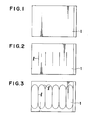
- a square-shaped body member 1 which is square as shown in Fig. 1 and is formed of a laminated material composed of a combination of at least two materials out of paper, synthetic resin and metal foil.
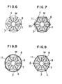
- a mandrel which forms the body member 1 into a preliminarily formed container C' is formed into curved surfaces 3 by inwardly depressing sides of a suitable polygon as shown in Figs. 4, 5 and 6, and projected portions 4 are formed on boundaries between the adjacent curved surfaces 3, 3 to provide a sectional shape like a starfish. Adjacent upper'and lower portions of the projected portions 4 are continuously joined each other in a circular fashion to provide body forming recess portions 5 having ends shaped to restrict said curved surfaces 3.
- Cylindrical portions 6, 6 equal in outside diameter to the projected portions 5 are provided on upper and lower portions of the recess portions 5.
- One end of the side of the body member 1 is held by a holder (not shown) having a groove, which is provided within the projected portion 4 on the mandrel M provided with a keep member 10 through a packing 9 at the upper end thereof and which has the same construction as that normally used during molding of a cup. As shown in Fig.
- the mandrel M is rotated and wound while bringing an upper end of the body member 1 into abutment with the lower end of the packing 9, and the mandrel M is rotated once so that the other side end of the body member 1 is superposed, in which state, they are adhered together by way of a supersonic seal or heat seal to form a cylindrical configuration.
- a disc-like closing member 2 separately prepared on an open end of the body member 1 is fixed by the same means as the method normally used for manufacturing a bottom of a paper cup so that it is formed into a preliminarily formed container C'.
- Vacuum attraction undergoes through the small holes 8, by a vacuum attraction source (not shown) in connection with the attractive hole 7 through the hole provided in the center of the keep member 10 of the mandrel M, to depress the body member 1 along the curved surfaces 3 of the mandrel M.
- a portion of the body member 1 where it contacts the projected portion 4 of the mandrel M is an edge line 20 and similarly, a portion thereof where it contacts the curved surface 3 is to be inwardly depressed. Therefore, as shown by the oblique lines of Fig. 7, a prismatic (more than a triangle) body portion 11 whose each surface is inwardly depressed is formed which body portion coincides with a sectional shape of the mandrel M.
- a preliminarily formed container C' having the body portion 11 is disengaged from the mandrel M by feeding compressed air from the samll holes 8 through the attractive hole 7 conversely to the vacuum attraction.
- juice or the like is filled at a high pressure of approximately 90°C from an unclosed open end, and a separately prepared closing member 12 is fixed to form a container C (shown in Fig. 12).
- both ends of the body member 1 are adhered beforehand as shown in Fig. 11 by the process separately from the manufacturing method of the present invention to provide a cylindrical configuration, and a closing member 2 is fixed to one open end and molded, after which it is moutned on the mandrel M so that the open end contacts the lower end of the packing 9 to form an angled and cylindrical body portion 11.
- straight creases £ are provied beforehand on the body member 1 at the intervals substantially equal in length to the distance between the projected portions 4 adjacent each other of the mandrel M, more preferably, as shown in Fig. 3, creases £' by which adjacent upper and lower ends of the creases l are continuously joined in arc-sahped fashion. Then, the body portion 11 will be an angled and cylindrical configuration when the preliminarily formed container is formed.
- the distance between the deepest portion of the curved surface 3 of the mandrel M and the body member 1 is extremely short as compared with the preliminary formed container formed of a flat body member as in the above-described embodiment as shown in Fig. 9.
- a portion in the vicinity of the edge line 20 which is most difficult to form and a portion by which upper and lower ends of the edge line 20 are joined in a circular fashion have been formed as the creases l and k' to some extent, and therefore, it is possible to form a depression simply and clearly by the body portion 11.
- the body member can be depressed by vacuum attraction inwardly of the mandrel without making any other jig or the like contact with the body member. Therefore, the surface of the body member is not scratched nor wrinkled to accurately provide a polygonal configuration without impairing an external appearance.
- the body member is to be bended by movement of the jig, if attending to one point of the body member, the jig merely passes through once whereas in the system of the present invention, the vacuum attractive force is simultaneously applied to the whole body member, and therefore, non-smoothing time can be prolonged to accurately provide a polygonal configuration.
- a body portion can be easily depressed by vaccum attraction into a polygonal configuration and a beautiful shape in conformity with the creases may be obtained.
Abstract
Description
- The present invention relates to a method for manufacturing a paper container in which a body portion is formed into a polygonal shape in section in order to prevent the body portion from being deformed into an irregular shape due to a pressure difference between interior and exterior of the container produced when the content is cooled after the container has been filled with juice or the like at a high temperature and sealed. A preliminarily formed container, wherein a closing member is secured to one of upper and lower open ends of a cylindrical body member, is mounted on a mandrel, which is polygonal and has a sectional shape in which sides constituting a polygon are inwardly curved, and the body member is subjected to vacuum attraction through an attractive hole provided in an mandrel and is depressed while adjusting to a sectional shape of the mandrel to form a polygon.
- In the past, in a paper container for filling with juice or the like at a high temperature, the way of thinking has been known in which creases of regular shape are provided on a body portion and portions surrounded by the creases are intentionally deformed to prevent depression and irregular deformation of a container caused by a negative pressure phenomenon resulting from cooling of filled contents after having been filled and sealed. However, even in the case of the container in which the body portion is foremd with the creases, the body portion itself is formed of a relatively thick material in terms of strength and has a considerable rigidity, and therefore, the container is not always deformed (depressed) into a shape as initially set but it is awkardly deformed to impair quality and appearance.
- In view of the foregoing, as means for solving the above-described problems, a method has been proposed in which not only creases are provided on the body portion but portions surrounded by the creases and to be deformed due to the negative pressure phenomenon are depressed beforehand to some extent prior to.filling with contents to intentionally and regularly produce deformation due to the negative pressure phenomenon after the content has been filled.
- To realize such a method as described above, the present inventor has already filed an European patent application No. 82105321.2.
- In the manufacturing method of this application, the body portion is pressed from the outside on the mandrel and formed by a vertically movable jig. However, this application has problems in that since the process is complicated, the operating efficiency is poor to damage the surface of the body portion and to wrinkle the same, impairing an appearance, and it is difficult to evenly press the whole body member and is impossible to sufficiently depress the body portion.
- The present invention relates to a method for manufacturing a container in which closing members are provided on upper and lower open ends of an angled and cylindrical body portion. A closing member is secured to one open end of a cylindrically formed body member to form a preliminarily formed container, the preliminarily formed container is mounted on a mandrel, which has a sectional shape of a curved surface obtained by inwardly depressing sides of a suitable polygon and in which each surface thereof is provided with small holes in connection with an inner attractive hole, the body portion being subjected to vacuum attraction through the attractive hole and depressed while adjusting to a sectional shape of the mandrel, and compressed air is fed through the attractive hole to disengage the preliminarily formed container from the mandrel to form an angled and cylindrical container.
-
- Fig. 1 is a developed view of a first embodiment of a body member of a container according to the present invention;
- Fig. 2 is a developed view of a second embodiment of the same;
- Fig. 3 is a developed view of a third embodiment of the same;
- Fig. 4 is a perspective view of a mandrel used in connection with the present invention;
- Fig. 5 is a side view of the side portion of the same;
- Fig. 6 is a sectional view taken on line A-A of Fig. 5;
- Fig. 7 is a sectional view taken on line A-A showing a body depressed;
- Fig. 8 is a sectional view taken on line A-A in which a preliminarily formed container which has used the body member of Fig. 1 is mounted on the mandrel;
- Fig. 9 is a sectional view taken on line A-A which likewise uses the body member shown in Fig. 2;
- Fig. 10 is a perspective view showing a first embodiment in which a preliminarily formed container is mounted on the mandrel;
- Fig. 11 is a perspective view showing the second embodiment;
and - Fig. 12 is a perspective view showing a container manufactured by the manufacturing method of the present invention.
- Embodiments of the present invention will be described with reference to the drawings.
- A square-
shaped body member 1, which is square as shown in Fig. 1 and is formed of a laminated material composed of a combination of at least two materials out of paper, synthetic resin and metal foil. A mandrel which forms thebody member 1 into a preliminarily formed container C' is formed intocurved surfaces 3 by inwardly depressing sides of a suitable polygon as shown in Figs. 4, 5 and 6, and projectedportions 4 are formed on boundaries between the adjacentcurved surfaces portions 4 are continuously joined each other in a circular fashion to provide body formingrecess portions 5 having ends shaped to restrict saidcurved surfaces 3.Cylindrical portions portions 5 are provided on upper and lower portions of therecess portions 5. The suitable number ofsmall holes 8, which are in connection with anatrractive hole 7 axially provided, are provided in the surface of the body-formingrecess portions 5. One end of the side of thebody member 1 is held by a holder (not shown) having a groove, which is provided within the projectedportion 4 on the mandrel M provided with akeep member 10 through apacking 9 at the upper end thereof and which has the same construction as that normally used during molding of a cup. As shown in Fig. 10, the mandrel M is rotated and wound while bringing an upper end of thebody member 1 into abutment with the lower end of thepacking 9, and the mandrel M is rotated once so that the other side end of thebody member 1 is superposed, in which state, they are adhered together by way of a supersonic seal or heat seal to form a cylindrical configuration. A disc-like closing member 2 separately prepared on an open end of thebody member 1 is fixed by the same means as the method normally used for manufacturing a bottom of a paper cup so that it is formed into a preliminarily formed container C'. - Vacuum attraction undergoes through the
small holes 8, by a vacuum attraction source (not shown) in connection with theattractive hole 7 through the hole provided in the center of thekeep member 10 of the mandrel M, to depress thebody member 1 along thecurved surfaces 3 of the mandrel M. As a consequence, a portion of thebody member 1 where it contacts the projectedportion 4 of the mandrel M is anedge line 20 and similarly, a portion thereof where it contacts thecurved surface 3 is to be inwardly depressed. Therefore, as shown by the oblique lines of Fig. 7, a prismatic (more than a triangle) body portion 11 whose each surface is inwardly depressed is formed which body portion coincides with a sectional shape of the mandrel M. - Next, a preliminarily formed container C' having the body portion 11 is disengaged from the mandrel M by feeding compressed air from the
samll holes 8 through theattractive hole 7 conversely to the vacuum attraction. - Thereafter, juice or the like is filled at a high pressure of approximately 90°C from an unclosed open end, and a separately prepared
closing member 12 is fixed to form a container C (shown in Fig. 12). - In a further embodiment of the present invention other than the above-described embodiment, in forming a preliminarily formed container C', both ends of the
body member 1 are adhered beforehand as shown in Fig. 11 by the process separately from the manufacturing method of the present invention to provide a cylindrical configuration, and aclosing member 2 is fixed to one open end and molded, after which it is moutned on the mandrel M so that the open end contacts the lower end of thepacking 9 to form an angled and cylindrical body portion 11. - As shown in Fig. 2, straight creases £ are provied beforehand on the
body member 1 at the intervals substantially equal in length to the distance between the projectedportions 4 adjacent each other of the mandrel M, more preferably, as shown in Fig. 3, creases £' by which adjacent upper and lower ends of the creases ℓ are continuously joined in arc-sahped fashion. Then, the body portion 11 will be an angled and cylindrical configuration when the preliminarily formed container is formed. Therefore, when it is mounted on the mandrel M for vacuum attraction, the distance between the deepest portion of thecurved surface 3 of the mandrel M and thebody member 1 is extremely short as compared with the preliminary formed container formed of a flat body member as in the above-described embodiment as shown in Fig. 9. In addition, a portion in the vicinity of theedge line 20 which is most difficult to form and a portion by which upper and lower ends of theedge line 20 are joined in a circular fashion have been formed as the creases ℓ and k' to some extent, and therefore, it is possible to form a depression simply and clearly by the body portion 11. - If the
small holes 8 for attraction and disengagement provided in the mandrel M are provided not only in thecurved surfaces 3 but in the projectedportions 4,a portion in the vicinity of theedge line 20 of the body portion 11 to which a greatest load is applied is brought powerfully into close contact with the projectedportion 4 of the mandrel M to form a moredefinite edge line 20. - As described above, in the present invention, different from a conventional method for pressing a body member on the mandrel by mechanical means from outside, the body member can be depressed by vacuum attraction inwardly of the mandrel without making any other jig or the like contact with the body member. Therefore, the surface of the body member is not scratched nor wrinkled to accurately provide a polygonal configuration without impairing an external appearance. Moreover, since in the conventional pressing system, the body member is to be bended by movement of the jig, if attending to one point of the body member, the jig merely passes through once whereas in the system of the present invention, the vacuum attractive force is simultaneously applied to the whole body member, and therefore, non-smoothing time can be prolonged to accurately provide a polygonal configuration.
- There are two methods for mounting a preliminarily formed container on a mandrel, one is to effect this after a preliminarily formed container is preformed, and the other is to effect his simultaneously while forming a preliminarily formed container on the mandrel. These methods are selectively employed.
- Furthermore, if creases are provided beforehand on a body member of a prelimarily formed container, a body portion can be easily depressed by vaccum attraction into a polygonal configuration and a beautiful shape in conformity with the creases may be obtained.
Claims (8)
Applications Claiming Priority (8)
| Application Number | Priority Date | Filing Date | Title |
|---|---|---|---|
| JP58124448A JPS6015140A (en) | 1983-07-08 | 1983-07-08 | Manufacture of square pillar vessel |
| JP58124447A JPS6015139A (en) | 1983-07-08 | 1983-07-08 | Manufacture of square pillar vessel |
| JP124448/83 | 1983-07-08 | ||
| JP124450/83 | 1983-07-08 | ||
| JP124446/83 | 1983-07-08 | ||
| JP58124450A JPS6015141A (en) | 1983-07-08 | 1983-07-08 | Manufacture of square pillar vessel |
| JP124447/83 | 1983-07-08 | ||
| JP58124446A JPS6015138A (en) | 1983-07-08 | 1983-07-08 | Manufacture of square pillar vessel |
Publications (3)
| Publication Number | Publication Date |
|---|---|
| EP0131862A2 true EP0131862A2 (en) | 1985-01-23 |
| EP0131862A3 EP0131862A3 (en) | 1987-06-03 |
| EP0131862B1 EP0131862B1 (en) | 1990-09-26 |
Family
ID=27471043
Family Applications (1)
| Application Number | Title | Priority Date | Filing Date |
|---|---|---|---|
| EP84107878A Expired - Lifetime EP0131862B1 (en) | 1983-07-08 | 1984-07-05 | Method for manufacturing an angled and cylindrical container |
Country Status (4)
| Country | Link |
|---|---|
| US (2) | US4581003A (en) |
| EP (1) | EP0131862B1 (en) |
| AU (1) | AU571880B2 (en) |
| DE (1) | DE3483286D1 (en) |
Cited By (3)
| Publication number | Priority date | Publication date | Assignee | Title |
|---|---|---|---|---|
| EP0224316A1 (en) * | 1985-11-25 | 1987-06-03 | Shell Internationale Researchmaatschappij B.V. | Hot fill thermoplastic container |
| EP0437835A1 (en) * | 1989-12-27 | 1991-07-24 | Nec Corporation | Frame synchronization system among multiple radio base stations for TDMA digital mobile communication system |
| DE102011113347A1 (en) * | 2011-09-15 | 2013-03-21 | Feldmann+Schultchen Design Studios Gmbh | Drinking cup made of foldable flat material |
Families Citing this family (34)
| Publication number | Priority date | Publication date | Assignee | Title |
|---|---|---|---|---|
| US5580624A (en) | 1992-08-11 | 1996-12-03 | E. Khashoggi Industries | Food and beverage containers made from inorganic aggregates and polysaccharide, protein, or synthetic organic binders, and the methods of manufacturing such containers |
| US5830548A (en) | 1992-08-11 | 1998-11-03 | E. Khashoggi Industries, Llc | Articles of manufacture and methods for manufacturing laminate structures including inorganically filled sheets |
| US5641584A (en) | 1992-08-11 | 1997-06-24 | E. Khashoggi Industries | Highly insulative cementitious matrices and methods for their manufacture |
| JPH08500075A (en) | 1992-08-11 | 1996-01-09 | イー・カショーギ・インダストリーズ | Hydrating cohesive container |
| US5658603A (en) | 1992-08-11 | 1997-08-19 | E. Khashoggi Industries | Systems for molding articles having an inorganically filled organic polymer matrix |
| US5665439A (en) | 1992-08-11 | 1997-09-09 | E. Khashoggi Industries | Articles of manufacture fashioned from hydraulically settable sheets |
| US5631097A (en) | 1992-08-11 | 1997-05-20 | E. Khashoggi Industries | Laminate insulation barriers having a cementitious structural matrix and methods for their manufacture |
| US5580409A (en) | 1992-08-11 | 1996-12-03 | E. Khashoggi Industries | Methods for manufacturing articles of manufacture from hydraulically settable sheets |
| US5506046A (en) | 1992-08-11 | 1996-04-09 | E. Khashoggi Industries | Articles of manufacture fashioned from sheets having a highly inorganically filled organic polymer matrix |
| US5928741A (en) | 1992-08-11 | 1999-07-27 | E. Khashoggi Industries, Llc | Laminated articles of manufacture fashioned from sheets having a highly inorganically filled organic polymer matrix |
| US5545450A (en) | 1992-08-11 | 1996-08-13 | E. Khashoggi Industries | Molded articles having an inorganically filled organic polymer matrix |
| US5800647A (en) | 1992-08-11 | 1998-09-01 | E. Khashoggi Industries, Llc | Methods for manufacturing articles from sheets having a highly inorganically filled organic polymer matrix |
| US5453310A (en) | 1992-08-11 | 1995-09-26 | E. Khashoggi Industries | Cementitious materials for use in packaging containers and their methods of manufacture |
| US5830305A (en) | 1992-08-11 | 1998-11-03 | E. Khashoggi Industries, Llc | Methods of molding articles having an inorganically filled organic polymer matrix |
| US5569148A (en) * | 1992-11-23 | 1996-10-29 | Bay Corrugated Container, Inc. | Method and apparatus for manufacturing pallet spacers |
| US5543186A (en) | 1993-02-17 | 1996-08-06 | E. Khashoggi Industries | Sealable liquid-tight, thin-walled containers made from hydraulically settable materials |
| US5762230A (en) | 1993-03-11 | 1998-06-09 | Policappelli; Nini | Laminated container |
| US5738921A (en) | 1993-08-10 | 1998-04-14 | E. Khashoggi Industries, Llc | Compositions and methods for manufacturing sealable, liquid-tight containers comprising an inorganically filled matrix |
| US5597433A (en) * | 1994-05-27 | 1997-01-28 | Panoramic, Inc. | Method and apparatus for manufacturing plastic canisters |
| DE19517394A1 (en) * | 1995-05-11 | 1996-11-14 | Rissen Gmbh Maschf | Method for producing thermally insulated, truncated conical beakers |
| FI120485B (en) | 1998-05-29 | 2009-11-13 | Lamican Oy | The container-forming unit |
| FI981219A (en) | 1998-05-29 | 1999-11-30 | Upm Kymmene Corp | Process and packaging machine for forming a filled package, material web and filled packaging |
| FI981223A (en) * | 1998-05-29 | 1999-11-30 | Upm Kymmene Corp | Method and equipment in a packaging machine |
| US6148519A (en) * | 1998-09-18 | 2000-11-21 | Donaldson Company, Inc. | Apparatus for installing a packing material in a muffler assembly; and methods thereof |
| TR200400866T4 (en) * | 2001-01-30 | 2004-06-21 | Seda S.P.A | Cardboard beverage container and method for producing it |
| US7703664B2 (en) * | 2004-10-15 | 2010-04-27 | Sonoco Development, Inc. | Paperboard container having curvilinear portion |
| BRPI0601188B1 (en) * | 2005-04-15 | 2018-06-26 | Seda S.P.A. | ISOLATED CONTAINER; METHOD OF MANUFACTURING THE SAME AND APPARATUS FOR MANUFACTURING |
| DE202005014177U1 (en) | 2005-09-08 | 2005-11-17 | Seda S.P.A., Arzano | Double-walled beaker comprises an inner wall formed by an inner beaker which is made of a fluid-tight plastic material, and is releasably inserted into an outer beaker forming the outer wall |
| PT1785370E (en) * | 2005-11-11 | 2008-06-06 | Seda Spa | Insulated cup |
| EP1785265A1 (en) * | 2005-11-14 | 2007-05-16 | SEDA S.p.A. | Device for producing a stacking projection on a container wall and container with same |
| DE202006018406U1 (en) | 2006-12-05 | 2008-04-10 | Seda S.P.A. | packaging |
| EP2221171B1 (en) * | 2009-02-20 | 2012-06-27 | Mohrbach Verpackungsmaschinen GmbH | Method and device for producing boxes made of paper or cardboard |
| EP2521646A1 (en) * | 2010-01-07 | 2012-11-14 | Mohrbach Verpackungsmaschinen GmbH | Method and device for producing boxes from paper or cardboard |
| US20130130877A1 (en) * | 2011-11-18 | 2013-05-23 | Shun-Fa Su | Paper Box Forming Machine |
Citations (6)
| Publication number | Priority date | Publication date | Assignee | Title |
|---|---|---|---|---|
| FR353684A (en) * | 1905-04-25 | 1905-09-18 | Friedrich Brandt | Process for the production of articles of paper and other similar materials |
| US1262289A (en) * | 1913-03-31 | 1918-04-09 | American Can Co | Paneled asparagus-can. |
| GB651097A (en) * | 1948-10-30 | 1951-03-14 | Dunlop Rubber Co | Improvements in or relating to the manufacture of corrugated rubber hose |
| DE1056359B (en) * | 1955-02-10 | 1959-04-30 | Continental Gummi Werke Ag | Mandrel for forming made of rubber or similar materials or folded cuffs. |
| US2892253A (en) * | 1953-03-02 | 1959-06-30 | Hugh A Hutchins | Method for making jet tubes |
| EP0068334A1 (en) * | 1981-06-19 | 1983-01-05 | Toppan Printing Co., Ltd. | Paper container for holding high-temperature liquid and method for filling the container with the liquid and sealing the same |
Family Cites Families (5)
| Publication number | Priority date | Publication date | Assignee | Title |
|---|---|---|---|---|
| US2063013A (en) * | 1934-09-19 | 1936-12-08 | Charles R Cooper | Packing can |
| US2037777A (en) * | 1935-02-04 | 1936-04-21 | Boothby Fibre Can Company | Container made of paper and method of making such container |
| US4106397A (en) * | 1974-06-14 | 1978-08-15 | Owens-Illinois, Inc. | Pick-up head assembly for use in apparatus for fabricating thermoplastic containers |
| US4306849A (en) * | 1976-03-10 | 1981-12-22 | Maryland Cup Corporation | Apparatus for providing bottom blanks for containers in a manufacturing process |
| DE3015112C2 (en) * | 1980-04-19 | 1984-09-06 | 4 P Nicolaus Kempten GmbH, 8960 Kempten | Device for producing a liquid-tight container |
-
1984
- 1984-07-03 US US06/627,435 patent/US4581003A/en not_active Expired - Fee Related
- 1984-07-05 DE DE8484107878T patent/DE3483286D1/en not_active Expired - Lifetime
- 1984-07-05 EP EP84107878A patent/EP0131862B1/en not_active Expired - Lifetime
- 1984-07-06 AU AU30370/84A patent/AU571880B2/en not_active Ceased
-
1985
- 1985-11-29 US US06/803,052 patent/US4622026A/en not_active Expired - Fee Related
Patent Citations (6)
| Publication number | Priority date | Publication date | Assignee | Title |
|---|---|---|---|---|
| FR353684A (en) * | 1905-04-25 | 1905-09-18 | Friedrich Brandt | Process for the production of articles of paper and other similar materials |
| US1262289A (en) * | 1913-03-31 | 1918-04-09 | American Can Co | Paneled asparagus-can. |
| GB651097A (en) * | 1948-10-30 | 1951-03-14 | Dunlop Rubber Co | Improvements in or relating to the manufacture of corrugated rubber hose |
| US2892253A (en) * | 1953-03-02 | 1959-06-30 | Hugh A Hutchins | Method for making jet tubes |
| DE1056359B (en) * | 1955-02-10 | 1959-04-30 | Continental Gummi Werke Ag | Mandrel for forming made of rubber or similar materials or folded cuffs. |
| EP0068334A1 (en) * | 1981-06-19 | 1983-01-05 | Toppan Printing Co., Ltd. | Paper container for holding high-temperature liquid and method for filling the container with the liquid and sealing the same |
Cited By (6)
| Publication number | Priority date | Publication date | Assignee | Title |
|---|---|---|---|---|
| EP0224316A1 (en) * | 1985-11-25 | 1987-06-03 | Shell Internationale Researchmaatschappij B.V. | Hot fill thermoplastic container |
| AU577481B2 (en) * | 1985-11-25 | 1988-09-22 | Shell Internationale Research Maatschappij B.V. | Hot fill thermoplastic container |
| EP0437835A1 (en) * | 1989-12-27 | 1991-07-24 | Nec Corporation | Frame synchronization system among multiple radio base stations for TDMA digital mobile communication system |
| US5293380A (en) * | 1989-12-27 | 1994-03-08 | Nec Corporation | Frame synchronization system among multiple radio base stations for TDMA digital mobile communications system |
| DE102011113347A1 (en) * | 2011-09-15 | 2013-03-21 | Feldmann+Schultchen Design Studios Gmbh | Drinking cup made of foldable flat material |
| US9345350B2 (en) | 2011-09-15 | 2016-05-24 | Feldmann + Schultchen Design Studios GmbH | Drinking cup made of foldable flat material |
Also Published As
| Publication number | Publication date |
|---|---|
| EP0131862A3 (en) | 1987-06-03 |
| US4581003A (en) | 1986-04-08 |
| EP0131862B1 (en) | 1990-09-26 |
| US4622026A (en) | 1986-11-11 |
| AU3037084A (en) | 1985-01-10 |
| DE3483286D1 (en) | 1990-10-31 |
| AU571880B2 (en) | 1988-04-28 |
Similar Documents
| Publication | Publication Date | Title |
|---|---|---|
| EP0131862A2 (en) | Method for manufacturing an angled and cylindrical container | |
| EP0467002B1 (en) | Method of manufacturing labeled containers | |
| EP0148527B1 (en) | Seal with tear lip for containers | |
| US5487465A (en) | Container carrier | |
| US4801347A (en) | Method of producing a packaging tray | |
| US4386925A (en) | Apparatus for producing a tear line in the multi-layered foil of a cigarette pack | |
| US3104012A (en) | Contamination proof package | |
| JPH04119209A (en) | Device for combination forming junction, which can be overhauled, between adjacent surface member and manufacture of said device for combination | |
| JPS6355076A (en) | Vessel into which novel valve is incorporated and manufacture thereof | |
| US5013878A (en) | Induction heat sealing lap-seamed containers to non-metallic closures | |
| CA1223532A (en) | Paper container for hot fillable liquids | |
| US5331791A (en) | Method and apparatus for the manufacture of a resealable package | |
| US3472723A (en) | Container manufacture | |
| US3191508A (en) | Method of manufacturing containers | |
| KR20050038655A (en) | Tin can with a foil closure membrane | |
| JPH07148832A (en) | Thermoforming device | |
| GB2108465A (en) | Container sealing | |
| JPH06179462A (en) | Tubular container and method for molding aluminum head core | |
| JPS6316213B2 (en) | ||
| JPH0130356Y2 (en) | ||
| JPH07304122A (en) | Formation of package | |
| JPH0215379B2 (en) | ||
| JPH052445Y2 (en) | ||
| JPS6331951Y2 (en) | ||
| JP2571298Y2 (en) | Resealable cylindrical container |
Legal Events
| Date | Code | Title | Description |
|---|---|---|---|
| PUAI | Public reference made under article 153(3) epc to a published international application that has entered the european phase |
Free format text: ORIGINAL CODE: 0009012 |
|
| AK | Designated contracting states |
Designated state(s): DE FR GB IT NL |
|
| PUAL | Search report despatched |
Free format text: ORIGINAL CODE: 0009013 |
|
| AK | Designated contracting states |
Kind code of ref document: A3 Designated state(s): DE FR GB IT NL |
|
| 17P | Request for examination filed |
Effective date: 19871127 |
|
| 17Q | First examination report despatched |
Effective date: 19880725 |
|
| GRAA | (expected) grant |
Free format text: ORIGINAL CODE: 0009210 |
|
| AK | Designated contracting states |
Kind code of ref document: B1 Designated state(s): DE FR GB IT NL |
|
| REF | Corresponds to: |
Ref document number: 3483286 Country of ref document: DE Date of ref document: 19901031 |
|
| ET | Fr: translation filed | ||
| ITF | It: translation for a ep patent filed |
Owner name: SAIC BREVETTI S.R.L. |
|
| PG25 | Lapsed in a contracting state [announced via postgrant information from national office to epo] |
Ref country code: GB Effective date: 19910705 |
|
| PLBE | No opposition filed within time limit |
Free format text: ORIGINAL CODE: 0009261 |
|
| STAA | Information on the status of an ep patent application or granted ep patent |
Free format text: STATUS: NO OPPOSITION FILED WITHIN TIME LIMIT |
|
| 26N | No opposition filed | ||
| PG25 | Lapsed in a contracting state [announced via postgrant information from national office to epo] |
Ref country code: NL Effective date: 19920201 |
|
| GBPC | Gb: european patent ceased through non-payment of renewal fee | ||
| NLV4 | Nl: lapsed or anulled due to non-payment of the annual fee | ||
| PG25 | Lapsed in a contracting state [announced via postgrant information from national office to epo] |
Ref country code: FR Effective date: 19920331 |
|
| PG25 | Lapsed in a contracting state [announced via postgrant information from national office to epo] |
Ref country code: DE Effective date: 19920401 |
|
| REG | Reference to a national code |
Ref country code: FR Ref legal event code: ST |