EP0131455A2 - Tamper-proof identification card and identification system - Google Patents
Tamper-proof identification card and identification system Download PDFInfo
- Publication number
- EP0131455A2 EP0131455A2 EP84304645A EP84304645A EP0131455A2 EP 0131455 A2 EP0131455 A2 EP 0131455A2 EP 84304645 A EP84304645 A EP 84304645A EP 84304645 A EP84304645 A EP 84304645A EP 0131455 A2 EP0131455 A2 EP 0131455A2
- Authority
- EP
- European Patent Office
- Prior art keywords
- support member
- card
- identification card
- identification
- code
- Prior art date
- Legal status (The legal status is an assumption and is not a legal conclusion. Google has not performed a legal analysis and makes no representation as to the accuracy of the status listed.)
- Withdrawn
Links
- 239000011159 matrix material Substances 0.000 claims description 17
- 229920000728 polyester Polymers 0.000 claims description 8
- 238000012795 verification Methods 0.000 claims description 7
- 238000001429 visible spectrum Methods 0.000 claims 2
- 229920001577 copolymer Polymers 0.000 claims 1
- 238000001228 spectrum Methods 0.000 claims 1
- 239000010410 layer Substances 0.000 description 22
- 239000004033 plastic Substances 0.000 description 7
- 229920003023 plastic Polymers 0.000 description 7
- -1 4000 oersteds Chemical compound 0.000 description 5
- 239000000463 material Substances 0.000 description 4
- ZWEHNKRNPOVVGH-UHFFFAOYSA-N 2-Butanone Chemical compound CCC(C)=O ZWEHNKRNPOVVGH-UHFFFAOYSA-N 0.000 description 3
- CSCPPACGZOOCGX-UHFFFAOYSA-N Acetone Chemical compound CC(C)=O CSCPPACGZOOCGX-UHFFFAOYSA-N 0.000 description 3
- XEKOWRVHYACXOJ-UHFFFAOYSA-N Ethyl acetate Chemical compound CCOC(C)=O XEKOWRVHYACXOJ-UHFFFAOYSA-N 0.000 description 3
- 239000004698 Polyethylene Substances 0.000 description 3
- 238000004519 manufacturing process Methods 0.000 description 3
- 238000000034 method Methods 0.000 description 3
- 229920000573 polyethylene Polymers 0.000 description 3
- 229920002635 polyurethane Polymers 0.000 description 3
- 239000004814 polyurethane Substances 0.000 description 3
- 239000002904 solvent Substances 0.000 description 3
- 210000003128 head Anatomy 0.000 description 2
- UCNNJGDEJXIUCC-UHFFFAOYSA-L hydroxy(oxo)iron;iron Chemical compound [Fe].O[Fe]=O.O[Fe]=O UCNNJGDEJXIUCC-UHFFFAOYSA-L 0.000 description 2
- 239000000696 magnetic material Substances 0.000 description 2
- 230000003287 optical effect Effects 0.000 description 2
- 239000000126 substance Substances 0.000 description 2
- 239000004677 Nylon Substances 0.000 description 1
- 239000000853 adhesive Substances 0.000 description 1
- 230000001070 adhesive effect Effects 0.000 description 1
- 238000010276 construction Methods 0.000 description 1
- 230000032798 delamination Effects 0.000 description 1
- 238000010586 diagram Methods 0.000 description 1
- 230000000694 effects Effects 0.000 description 1
- 238000004049 embossing Methods 0.000 description 1
- 229940093499 ethyl acetate Drugs 0.000 description 1
- 235000019439 ethyl acetate Nutrition 0.000 description 1
- 238000003475 lamination Methods 0.000 description 1
- 229920001778 nylon Polymers 0.000 description 1
- 239000003921 oil Substances 0.000 description 1
- 230000035515 penetration Effects 0.000 description 1
- 229920000642 polymer Polymers 0.000 description 1
- 230000001681 protective effect Effects 0.000 description 1
- 230000005855 radiation Effects 0.000 description 1
- 238000007789 sealing Methods 0.000 description 1
- 239000002356 single layer Substances 0.000 description 1
- 230000000007 visual effect Effects 0.000 description 1
Images

Classifications
-
- B—PERFORMING OPERATIONS; TRANSPORTING
- B42—BOOKBINDING; ALBUMS; FILES; SPECIAL PRINTED MATTER
- B42D—BOOKS; BOOK COVERS; LOOSE LEAVES; PRINTED MATTER CHARACTERISED BY IDENTIFICATION OR SECURITY FEATURES; PRINTED MATTER OF SPECIAL FORMAT OR STYLE NOT OTHERWISE PROVIDED FOR; DEVICES FOR USE THEREWITH AND NOT OTHERWISE PROVIDED FOR; MOVABLE-STRIP WRITING OR READING APPARATUS
- B42D25/00—Information-bearing cards or sheet-like structures characterised by identification or security features; Manufacture thereof
- B42D25/40—Manufacture
- B42D25/45—Associating two or more layers
-
- G—PHYSICS
- G06—COMPUTING; CALCULATING OR COUNTING
- G06K—GRAPHICAL DATA READING; PRESENTATION OF DATA; RECORD CARRIERS; HANDLING RECORD CARRIERS
- G06K19/00—Record carriers for use with machines and with at least a part designed to carry digital markings
- G06K19/06—Record carriers for use with machines and with at least a part designed to carry digital markings characterised by the kind of the digital marking, e.g. shape, nature, code
- G06K19/08—Record carriers for use with machines and with at least a part designed to carry digital markings characterised by the kind of the digital marking, e.g. shape, nature, code using markings of different kinds or more than one marking of the same kind in the same record carrier, e.g. one marking being sensed by optical and the other by magnetic means
-
- B—PERFORMING OPERATIONS; TRANSPORTING
- B42—BOOKBINDING; ALBUMS; FILES; SPECIAL PRINTED MATTER
- B42D—BOOKS; BOOK COVERS; LOOSE LEAVES; PRINTED MATTER CHARACTERISED BY IDENTIFICATION OR SECURITY FEATURES; PRINTED MATTER OF SPECIAL FORMAT OR STYLE NOT OTHERWISE PROVIDED FOR; DEVICES FOR USE THEREWITH AND NOT OTHERWISE PROVIDED FOR; MOVABLE-STRIP WRITING OR READING APPARATUS
- B42D25/00—Information-bearing cards or sheet-like structures characterised by identification or security features; Manufacture thereof
- B42D25/20—Information-bearing cards or sheet-like structures characterised by identification or security features; Manufacture thereof characterised by a particular use or purpose
- B42D25/23—Identity cards
-
- B—PERFORMING OPERATIONS; TRANSPORTING
- B42—BOOKBINDING; ALBUMS; FILES; SPECIAL PRINTED MATTER
- B42D—BOOKS; BOOK COVERS; LOOSE LEAVES; PRINTED MATTER CHARACTERISED BY IDENTIFICATION OR SECURITY FEATURES; PRINTED MATTER OF SPECIAL FORMAT OR STYLE NOT OTHERWISE PROVIDED FOR; DEVICES FOR USE THEREWITH AND NOT OTHERWISE PROVIDED FOR; MOVABLE-STRIP WRITING OR READING APPARATUS
- B42D25/00—Information-bearing cards or sheet-like structures characterised by identification or security features; Manufacture thereof
- B42D25/30—Identification or security features, e.g. for preventing forgery
- B42D25/309—Photographs
-
- B—PERFORMING OPERATIONS; TRANSPORTING
- B42—BOOKBINDING; ALBUMS; FILES; SPECIAL PRINTED MATTER
- B42D—BOOKS; BOOK COVERS; LOOSE LEAVES; PRINTED MATTER CHARACTERISED BY IDENTIFICATION OR SECURITY FEATURES; PRINTED MATTER OF SPECIAL FORMAT OR STYLE NOT OTHERWISE PROVIDED FOR; DEVICES FOR USE THEREWITH AND NOT OTHERWISE PROVIDED FOR; MOVABLE-STRIP WRITING OR READING APPARATUS
- B42D25/00—Information-bearing cards or sheet-like structures characterised by identification or security features; Manufacture thereof
- B42D25/30—Identification or security features, e.g. for preventing forgery
- B42D25/36—Identification or security features, e.g. for preventing forgery comprising special materials
- B42D25/369—Magnetised or magnetisable materials
-
- G—PHYSICS
- G06—COMPUTING; CALCULATING OR COUNTING
- G06K—GRAPHICAL DATA READING; PRESENTATION OF DATA; RECORD CARRIERS; HANDLING RECORD CARRIERS
- G06K19/00—Record carriers for use with machines and with at least a part designed to carry digital markings
- G06K19/06—Record carriers for use with machines and with at least a part designed to carry digital markings characterised by the kind of the digital marking, e.g. shape, nature, code
- G06K19/08—Record carriers for use with machines and with at least a part designed to carry digital markings characterised by the kind of the digital marking, e.g. shape, nature, code using markings of different kinds or more than one marking of the same kind in the same record carrier, e.g. one marking being sensed by optical and the other by magnetic means
- G06K19/083—Constructional details
-
- B42D2033/16—
-
- B—PERFORMING OPERATIONS; TRANSPORTING
- B42—BOOKBINDING; ALBUMS; FILES; SPECIAL PRINTED MATTER
- B42D—BOOKS; BOOK COVERS; LOOSE LEAVES; PRINTED MATTER CHARACTERISED BY IDENTIFICATION OR SECURITY FEATURES; PRINTED MATTER OF SPECIAL FORMAT OR STYLE NOT OTHERWISE PROVIDED FOR; DEVICES FOR USE THEREWITH AND NOT OTHERWISE PROVIDED FOR; MOVABLE-STRIP WRITING OR READING APPARATUS
- B42D25/00—Information-bearing cards or sheet-like structures characterised by identification or security features; Manufacture thereof
- B42D25/30—Identification or security features, e.g. for preventing forgery
- B42D25/36—Identification or security features, e.g. for preventing forgery comprising special materials
- B42D25/378—Special inks
- B42D25/387—Special inks absorbing or reflecting ultraviolet light
-
- B—PERFORMING OPERATIONS; TRANSPORTING
- B42—BOOKBINDING; ALBUMS; FILES; SPECIAL PRINTED MATTER
- B42D—BOOKS; BOOK COVERS; LOOSE LEAVES; PRINTED MATTER CHARACTERISED BY IDENTIFICATION OR SECURITY FEATURES; PRINTED MATTER OF SPECIAL FORMAT OR STYLE NOT OTHERWISE PROVIDED FOR; DEVICES FOR USE THEREWITH AND NOT OTHERWISE PROVIDED FOR; MOVABLE-STRIP WRITING OR READING APPARATUS
- B42D25/00—Information-bearing cards or sheet-like structures characterised by identification or security features; Manufacture thereof
- B42D25/40—Manufacture
- B42D25/45—Associating two or more layers
- B42D25/465—Associating two or more layers using chemicals or adhesives
- B42D25/47—Associating two or more layers using chemicals or adhesives using adhesives
-
- Y—GENERAL TAGGING OF NEW TECHNOLOGICAL DEVELOPMENTS; GENERAL TAGGING OF CROSS-SECTIONAL TECHNOLOGIES SPANNING OVER SEVERAL SECTIONS OF THE IPC; TECHNICAL SUBJECTS COVERED BY FORMER USPC CROSS-REFERENCE ART COLLECTIONS [XRACs] AND DIGESTS
- Y10—TECHNICAL SUBJECTS COVERED BY FORMER USPC
- Y10S—TECHNICAL SUBJECTS COVERED BY FORMER USPC CROSS-REFERENCE ART COLLECTIONS [XRACs] AND DIGESTS
- Y10S283/00—Printed matter
- Y10S283/904—Credit card
Definitions
- the present invention relates to the field of identification cards, and, more particularly, to identification cards containing encoded information.
- Plastic personal verification or identification cards are becoming increasingly common. There are for example credit cards, bank cards, and cards allowing various privileges, for example, to drive a car or to have access to a restricted location. Although these cards provide a wide variety of functions and are often used in different ways, they may all be considered identification cards and it is important to ensure that the correct person possesses the correct identification card.
- the basic plastic card is no longer adequate either for identification or for security. Cards must contain additional information or identification to ensure that the proper person is using the card.
- Identification cards that need the most security have some personal identification on them so that a thief of a card cannot simply use the card.
- One example of this is bank cards which usually require a unique user identification number.
- this system has proven effective, it does not stop theft by persons who know the personal number of the owner of the card. Also, it is unsuitable for widespread use because everyone cannot be expected to learn different personal identification numbers for each credit card, bank card, and security card.
- Another solution is to include a photograph of the user on the card as is done on many driver's licenses and security cards. This too has been effective, but counterfeit cards can be made by replacing the pictures in stolen cards with other pictures.
- a third solution to the counterfeiting problem is the inclusion on the plastic cards of a magnetic strip containing particular information unique to each user. If only a few of all the possible codes on the magnetic strip are valid, then it is difficult to know which code to put on the strip, and thus, it is difficult to counterfeit such cards. This system, however, does not stop a thief from using the card nor does it prevent counterfeiters from manufacturing fake cards because valid codes can be read from a valid card and used on counterfeit cards.
- identification cards Another problem with the current plastic identification cards is that with their increased use, they are more susceptible to wearing out and are more likely to be exposed to a harmful environment. In certain work places identification cards come in contact with solvents which destroy the card. Cards can also be destroyed by exposure to extremes of temperature, a common condition at many military facilities. Even without the solvents and the temperature extremes,the practice of carrying cards in wallets, or their use in credit card machines causes the cards to wear out quickly.
- one object of this invention is a durable tamper-proof proof identification card which cannot easily be counterfeited.
- Another object of this invention is an identification card with multiple information fields which can be compared with one another to ensure positive identification of the bearer of the card.
- Another object of this invention is to provide an identification card that can be used to access additional information in a computer system.
- the tamper-proof and wear resistant identification card comprises a support member having front and rear surfaces, recording means such as high coercivity magnetic tape on one surface for storing magnetically encoded data, transparent layers overlying the front and rear surfaces of the support member, each transparent layer being bonded to the support layer and a screen imprinted with encoded data, such as a dot matrix or bar code on a first surface of one transparent layer where the first surface is adjacent the surface of the support member.
- the identity card is part of an identification system which comprises, in addition to the identity card, means for magnetic recording of data onto the magnetic tape of the identity card, means for reading the optically readable characters imprinted on the screen of the identity card, means for reading the magnetically encoded data and means for correlating the optically readable data and the magnetically encoded data on the card.
- the identification card of this invention contains encoded information which is bonded to the card so that any attempt to tamper with the card destroys the information.
- the encoded information is in the form of a matrix of ink dots which cannot be perceived by the human eye but which can be detected when exposed to ultraviolet radiation.
- the ink used has an affinity for the materials used to make up the multiple layers of the card and when delamination of the card is attempted, the ink dot code is either destroyed so that it can no longer be detected or altered so that it does not correspond with other information contained on the card.
- An added feature of the card of this invention is an additional recording means, which also contains an identification code.
- a magnetic strip containing a layer of high coercivity magnetic material is used as the recording means. Before the information from this magnetic strip is read, a magnetic reader applies a magnetic field to the strip strong enough to erase all the information from most magnetic strips, but not from the high coercivity material in the magnetic strip used in the card of this invention. A counterfeit card which does not use high magnetic field recording methods in conjunction with magnetic materials having a high enough coercivity for the magnetic strip will be detected by the card verification system of this invention.
- FIG. lA The front face of identification card 1 of this invention can be seen in Figure lA.
- Figure lB shows a rear view of the card.
- card 1 contains a photograph 2 approximately 1" x 1 3/4" (25.4-44.5 mm).
- Photograph 2 can be any standard photograph used in identification cards.
- the photograph need not be rectangular as shown.
- the photograph can be oval or square and of a size consistent to fit within the boundaries of the particular card.
- card 1 also contains an optically readable code, such as a dot matrix code 7 in one area referred to as a screen 7a.
- a dot matrix code 7 is written on a bond layer 35 between a front cover 30 and a front base 12.
- the dot matrix may be applied in an ink which is detectable only under a certain type of light, e.g. ultraviolet. It may be applied at a location on the bond layer 35 in a position to cover a portion of the photograph 2, but such placement is not critical.
- the one restriction on the placement of the dot matrix is that it must be placed at least 3/32" (2.4 mm) from the perimeter of the card to allow for proper lamination of the card and sealing of its edges.
- the screen 7 should also be slightly spaced from any areas of the card which may be embossed.
- the matrix of dots in the screen can comprise any desired code.
- the code consists of a pattern of dots placed horizontally and vertically on the face of the card. These dots can represent a sequence of characters in a unique identification code e.g. one chosen by a machine which controls the manufacture of the card.
- the choice of the code is not critical to the invention and can be a standard numeric or alphanumeric code which is generated by a computer according to some pseudo-random coded-generating procedure, many of which are well known in the art.
- the card also contains a label 3 which can hold any information relevant to the use of the card.
- the label 3 on military ID card 1 includes personal information, such as date of birth, height and colour of eyes, and service information, such as rank and branch of service.
- the label is on the same surface of the card as the photograph 2 and is made of a plastic onto which information can be typed or printed.
- Label 3 in the preferred embodiment also has the expiration date of the card printed on the background so security guards checking this ID can tell more easily whether the card has expired.
- the label 3 is located in a recess 3a in the base section 12 and is covered by bond 35 and front cover 30.
- the preferred embodiment of card 1 can also contain an embossed area 4 which may be used to encode information such as the name of the card owner or some identifying code like an account number. This is especially useful for transferring information from the card to receipts.
- the back of card 1 is shown in Figure 1B. It contains a magnetic strip 5 preferably containing recorded information which corresponds to the identification information stored in the dot matrix on the face of the card. In the preferred embodiment this magnetic strip is on the opposite surface of the card from the photograph.
- the magnetic strip in the preferred embodiment consists of a bottom layer of very high coercive force magnetic oxide, e.g. 4000 oersteds, and a top layer of standard coercive force magnetic oxide, e.g. 300 oersteds.
- a single layer of high coercivity tape can also be used instead of the double layer strip.
- a thin layer of protective laminate covers the tape.
- the high coercive force magnetic strip requires a special encoding head to record data.
- This encoding head provides "deep" encoding of data, ensuring the permanence of that data. Data recorded in this manner cannot be altered or erased by ordinary magnetic fields like permanent magnets, bulk tape erasers, etc., or by any field less than about 2500 oersteds.
- the verification station which reads this card can have a "selective erasure" field of approximately 500-1500 oersteds magnetic force. A counterfeit card not having the high coersivity tape would be partially erased by such a field and exposed as counterfeit.
- the back of the card would also contain an area 6 for instructions and rules for use of the card and a panel containing the signature of the card owner.
- the signature would be entered before the back cover is bonded to the card so that the signature could not be erased or altered without removing the card's cover.
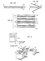
- FIGS 2A and 2B show views of the card, from the side and end edges respectively.
- the card is comprised of a support member 10, including a rear base 11 and a front base 12.
- the support member 10 is covered by a front cover 30 and a back cover 20 each made of transparent polyester.
- support member 10 includes rear base 11 and front base 12 each base being an opaque tensi- lized polyester.
- the front base 12 and rear base 11 are bonded together by bond 13 which is a thin layer of polyurethane with polyethylene on each side.
- the exposed surface of front base 12 is the front surface of support member 10 and the exposed surface of rear base 11 is the rear surface of support 10.
- the front base 12 contains, in the preferred embodiment, two shallow cutouts or recesses.
- Recess 2a which can be seen in Figure 1C holds photograph 2.
- Recess 3a also seen in Figure lC, holds label 3 and is approximately the same size as label 3.
- Layers of the card such as bases 11 and 12 may be made separately by well known techniques to the desired dimensions.
- the bases In order to receive a photo or label, the bases may be punched to create a recessed area of the same depth as the thickness of the photo or label.
- Bond 15 is attached to the rear surface of support member 10 via bond 15.
- Bond 15 like all the bonds used in the manufacture of the preferred embodiment of the card, consists of a polyurethane layer coated on each side with polyethylene. Although this type of bond is preferred for use with the polyester support, other types of adhesives are well known for use in bonding layers of identification cards together.
- Back cover 20 is clear polyester.
- Photo 2 and label 3 are inserted into recesses 2a and 3a, respectively.
- Screen 7 in the preferred embodiment overlies photograph 2.
- Dot matrix 7a containing an identification code is printed so that it covers at least a portion of the photograph 2 and a portion of support member 10.
- the dot matrix preferably is printed using micro-encapsulated ink supplied by a nylon ribbon carrier.
- the ink chosen for the preferred embodiment is not visible to the unaided human eye, but when the card is illuminated with long wave ultraviolet light (approximately 335 mm) the ink fluoresces and appears as yellow-green dots. These dots can then be sensed by a suitable optical reader.
- a bar code may be printed across a portion of or along an edge of the photograph in a machine readable medium which may be detected in the presence of ultraviolet or infra red light.
- the bar code is printed over a band of like-coloured ink, which is not responsive to the radiating light, thereby eliminating the visual presence of the bar code.
- the ink chosen to print the dot matrix has an affinity for polymers and organic-based materials.
- front cover 30, which is clear transparent polyester, is bonded to support member 10 via bond 35, the ink printed on bond layer 35 becomes permanently embedded in the support member 10, Fig. 2A and the front cover 30.
- Bond 35 is, e.g. a thin layer of polyurethane coated on both sides with polyethylene. Any attempt to delaminate the card to change the photograph destroys or alters the code in the dot matrix so that the code can no longer be correctly read by the machines designed to examine these cards.
- the identification card of the invention withstands temperatures from -50F to +250F (-45.5 to 121°C) and retaining its flexibility over that range. This card also resists penetration by chemicals, greases, oils, or solvents such as acetone, methylethylketone or ethylacetate. Tests on the card have shown it capable of withstanding 2,000 cycles of 90° flexures without showing a weakness and 200,000 cycles of 45° flexures without damage to the card. In addition, this card retains its flexibility and transparency with age.
- the identification card of this invention is tamper-proof because any attempt to remove the front cover 30 of the card destroys the code in the dot matrix. Furthermore, the high coercivity magnetic tape 5 on the rear of the card allows machine readers of these cards to employ a selective erasure field which will destroy any magnetic card code not recorded on high coercivity tape. Finally, the card is very resistant to wear, heat and exposure to chemicals.
- Figure 4 depicts schematically equipment used in making the identification card of the present invention.
- Data from a central processing unit 40 can be called up on a terminal 41 to obtain information on an individual whose identity card is being prepared. Information from the central processing centre is verified with the individual and the data may be changed if needed on the terminal 41. Any incorrect data or new data is entered in the central data processing centre.
- a kit containing the materials necessary to prepare the identification card is placed in a processing machine 42 which machine contains a key board for control and input of information, a printer, a photo-optic reader, an encoder-reader for magnetic tape and an embosser. Data from the central processing centre or from the individual is printed on the label 3 of the ID card.
- Data is encoded on the bond layer 35 and read into the photo-optic dot matrix reader. Additional verification data is encoded on the magnetic tape, the signature of the individual is placed on the rear base 11 and a photograph taken of the individual with camera 43. The support is inserted in the photo die cutter 44 to trim the photo and information label. The layers of the card are then assembled and laminated in laminator 45. Additional data may also be entered on the identification card by embossing after the card has been assembled and laminated together.
- Verification of the data encoded on the identification card when presented by a person is accomplished by inserting the card in a terminal capable of detecting and interpreting the type of optically and magnetically encoded information present on the card. If the data from both the optical and magnetic sources is consistent, the terminal would be programmed to verify the authenticity of the card. As a higher level of security, the terminal could be used to further verify the data with a central computer.
Abstract
A tamper-proof and wear resistant identification card having a support layer (10), a strip of magnetic tape (5) for containing encoded information, transparent layers (30, 20) covering the front and rear surfaces of the support layer and a screen of optically-readable encoded information (7) on a surface of one of the transparent layers (30).
Description
- The present invention relates to the field of identification cards, and, more particularly, to identification cards containing encoded information.
- Plastic personal verification or identification cards are becoming increasingly common. There are for example credit cards, bank cards, and cards allowing various privileges, for example, to drive a car or to have access to a restricted location. Although these cards provide a wide variety of functions and are often used in different ways, they may all be considered identification cards and it is important to ensure that the correct person possesses the correct identification card.
- These cards provide some of the most basic conveniences that most people now take for granted. Credit cards eliminate the necessity of carrying checkbooks or large amounts of cash. Bank cards give us access to checking and savings accounts when it is convenient for us, rather than when it is convenient for the bank. Other cards include passcards into government services (e.g., Social Security cards, welfare cards, driver's licenses) and into large organisations or facilities (e.g., factories, military bases). The plastic card has become an indispensible component of modern life.
- The biggest drawback to the use of such cards is that, when they are stolen or counterfeited, the entire society feels the effect. Credit card fraud costs consumers by requiring merchants to charge higher prices. Consumers also directly and indirectly bear the load caused by unauthorized use of bank cards, social security cards, and checks which are cashed using falseidentity.
- There are still other costs to society from fraudulent use of plastic cards. The use of counterfeited identification to gain unauthorized access to locations or accounts has far-reaching repercussions. To minimize the counterfeiting of security cards, increasingly elaborate security systems must be developed adding to the inconvenience of such systems and increasing these costs.
- The basic plastic card is no longer adequate either for identification or for security. Cards must contain additional information or identification to ensure that the proper person is using the card.
- Identification cards that need the most security have some personal identification on them so that a thief of a card cannot simply use the card. One example of this is bank cards which usually require a unique user identification number. Although this system has proven effective, it does not stop theft by persons who know the personal number of the owner of the card. Also, it is unsuitable for widespread use because everyone cannot be expected to learn different personal identification numbers for each credit card, bank card, and security card.
- Another solution is to include a photograph of the user on the card as is done on many driver's licenses and security cards. This too has been effective, but counterfeit cards can be made by replacing the pictures in stolen cards with other pictures.
- A third solution to the counterfeiting problem is the inclusion on the plastic cards of a magnetic strip containing particular information unique to each user. If only a few of all the possible codes on the magnetic strip are valid, then it is difficult to know which code to put on the strip, and thus, it is difficult to counterfeit such cards. This system, however, does not stop a thief from using the card nor does it prevent counterfeiters from manufacturing fake cards because valid codes can be read from a valid card and used on counterfeit cards.
- Another problem with the current plastic identification cards is that with their increased use, they are more susceptible to wearing out and are more likely to be exposed to a harmful environment. In certain work places identification cards come in contact with solvents which destroy the card. Cards can also be destroyed by exposure to extremes of temperature, a common condition at many military facilities. Even without the solvents and the temperature extremes,the practice of carrying cards in wallets, or their use in credit card machines causes the cards to wear out quickly.
- Accordingly, one object of this invention is a durable tamper-proof proof identification card which cannot easily be counterfeited.
- Another object of this invention is an identification card with multiple information fields which can be compared with one another to ensure positive identification of the bearer of the card.
- Yet, another object of this invention is to provide an identification card that can be used to access additional information in a computer system.
- To achieve the objects and in accordance with the purpose of the invention, as embodied and broadly described herein, the tamper-proof and wear resistant identification card comprises a support member having front and rear surfaces, recording means such as high coercivity magnetic tape on one surface for storing magnetically encoded data, transparent layers overlying the front and rear surfaces of the support member, each transparent layer being bonded to the support layer and a screen imprinted with encoded data, such as a dot matrix or bar code on a first surface of one transparent layer where the first surface is adjacent the surface of the support member. The identity card is part of an identification system which comprises, in addition to the identity card, means for magnetic recording of data onto the magnetic tape of the identity card, means for reading the optically readable characters imprinted on the screen of the identity card, means for reading the magnetically encoded data and means for correlating the optically readable data and the magnetically encoded data on the card.
- In the accompanying drawings:
- Figure 1A is a front view of an identification card of the invention showing an area for a photograph and an area for information identifying the card owner.
- Figure 1B is a rear view of the identification card of Fig. 1A showing a space for a signature and a strip of magnetic tape.
- Figure lC is a front view of an identification card of the invention with the base sections bonded together and the front and rear covers open.
- Figure 2A is a side view of the identification card of Fig. 1 with the layers laminated together.
- Figure 2B is an end view of the identification card of Fig. 1 with the base sections bonded together and the front and rear covers open.
- Figure 3 is an exploded side veiw of an identification card of the invention showing each of the layers of the card.
- Figure 4 is a schematic diagram of the equipment used to make an identification card of the invention and use it for identification.
- Reference will now be made in detail to a presently preferred embodiment of the invention, an example of which is illustrated in the accompanying drawings.
- The identification card of this invention contains encoded information which is bonded to the card so that any attempt to tamper with the card destroys the information. In one preferred embodiment, the encoded information is in the form of a matrix of ink dots which cannot be perceived by the human eye but which can be detected when exposed to ultraviolet radiation. The ink used has an affinity for the materials used to make up the multiple layers of the card and when delamination of the card is attempted, the ink dot code is either destroyed so that it can no longer be detected or altered so that it does not correspond with other information contained on the card.
- An added feature of the card of this invention is an additional recording means, which also contains an identification code. In a preferred embodiment, a magnetic strip containing a layer of high coercivity magnetic material is used as the recording means. Before the information from this magnetic strip is read, a magnetic reader applies a magnetic field to the strip strong enough to erase all the information from most magnetic strips, but not from the high coercivity material in the magnetic strip used in the card of this invention. A counterfeit card which does not use high magnetic field recording methods in conjunction with magnetic materials having a high enough coercivity for the magnetic strip will be detected by the card verification system of this invention.
- The front face of identification card 1 of this invention can be seen in Figure lA. Figure lB shows a rear view of the card.
- In the preferred embodiment shown in Figures lA and 1B, card 1 contains a
photograph 2 approximately 1" x 1 3/4" (25.4-44.5 mm).Photograph 2 can be any standard photograph used in identification cards. The photograph need not be rectangular as shown. For example, the photograph can be oval or square and of a size consistent to fit within the boundaries of the particular card. - As shown in Fig. 1C, card 1 also contains an optically readable code, such as a dot matrix code 7 in one area referred to as a screen 7a. In the embodiment shown in the Figures,dot matrix 7 is written on a
bond layer 35 between afront cover 30 and afront base 12. The dot matrix may be applied in an ink which is detectable only under a certain type of light, e.g. ultraviolet. It may be applied at a location on thebond layer 35 in a position to cover a portion of thephotograph 2, but such placement is not critical. The one restriction on the placement of the dot matrix is that it must be placed at least 3/32" (2.4 mm) from the perimeter of the card to allow for proper lamination of the card and sealing of its edges. The screen 7 should also be slightly spaced from any areas of the card which may be embossed. - The matrix of dots in the screen can comprise any desired code. Preferably, the code consists of a pattern of dots placed horizontally and vertically on the face of the card. These dots can represent a sequence of characters in a unique identification code e.g. one chosen by a machine which controls the manufacture of the card. The choice of the code is not critical to the invention and can be a standard numeric or alphanumeric code which is generated by a computer according to some pseudo-random coded-generating procedure, many of which are well known in the art.
- In the preferred embodiment, the card also contains a
label 3 which can hold any information relevant to the use of the card. In the example of the card shown in Figure lA, thelabel 3 on military ID card 1 includes personal information, such as date of birth, height and colour of eyes, and service information, such as rank and branch of service. Preferably, the label is on the same surface of the card as thephotograph 2 and is made of a plastic onto which information can be typed or printed.Label 3 in the preferred embodiment also has the expiration date of the card printed on the background so security guards checking this ID can tell more easily whether the card has expired. In the finished card, thelabel 3 is located in a recess 3a in thebase section 12 and is covered bybond 35 andfront cover 30. - The preferred embodiment of card 1 can also contain an embossed
area 4 which may be used to encode information such as the name of the card owner or some identifying code like an account number. This is especially useful for transferring information from the card to receipts. - The back of card 1 is shown in Figure 1B. It contains a
magnetic strip 5 preferably containing recorded information which corresponds to the identification information stored in the dot matrix on the face of the card. In the preferred embodiment this magnetic strip is on the opposite surface of the card from the photograph. The magnetic strip in the preferred embodiment consists of a bottom layer of very high coercive force magnetic oxide, e.g. 4000 oersteds, and a top layer of standard coercive force magnetic oxide, e.g. 300 oersteds. A single layer of high coercivity tape can also be used instead of the double layer strip. A thin layer of protective laminate covers the tape. - The high coercive force magnetic strip requires a special encoding head to record data. This encoding head provides "deep" encoding of data, ensuring the permanence of that data. Data recorded in this manner cannot be altered or erased by ordinary magnetic fields like permanent magnets, bulk tape erasers, etc., or by any field less than about 2500 oersteds.
- This "deep" encoding of data provides another hinder- ance to counterfeiters. The verification station which reads this card can have a "selective erasure" field of approximately 500-1500 oersteds magnetic force. A counterfeit card not having the high coersivity tape would be partially erased by such a field and exposed as counterfeit.
- Preferably, the back of the card would also contain an
area 6 for instructions and rules for use of the card and a panel containing the signature of the card owner. The signature would be entered before the back cover is bonded to the card so that the signature could not be erased or altered without removing the card's cover. - Figures 2A and 2B show views of the card, from the side and end edges respectively. The card is comprised of a
support member 10, including a rear base 11 and afront base 12. Thesupport member 10 is covered by afront cover 30 and aback cover 20 each made of transparent polyester. - Each of these layers, as well as the other elements of the card, are shown in-more detail in the exploded view in Figure 3. In the preferred embodiment of the card shown in Figure 3,
support member 10 includes rear base 11 andfront base 12 each base being an opaque tensi- lized polyester. Thefront base 12 and rear base 11 are bonded together bybond 13 which is a thin layer of polyurethane with polyethylene on each side. The exposed surface offront base 12 is the front surface ofsupport member 10 and the exposed surface of rear base 11 is the rear surface ofsupport 10. Thefront base 12 contains, in the preferred embodiment, two shallow cutouts or recesses. Recess 2a which can be seen in Figure 1C holdsphotograph 2. Recess 3a, also seen in Figure lC, holdslabel 3 and is approximately the same size aslabel 3. These recesses allow the photo and label to be inserted into the bases and have their top surface flush with the surface of the base. - Layers of the card such as
bases 11 and 12 may be made separately by well known techniques to the desired dimensions. In order to receive a photo or label, the bases may be punched to create a recessed area of the same depth as the thickness of the photo or label. -
Magnetic strip 5 is attached to the rear surface ofsupport member 10 viabond 15.Bond 15, like all the bonds used in the manufacture of the preferred embodiment of the card, consists of a polyurethane layer coated on each side with polyethylene. Although this type of bond is preferred for use with the polyester support, other types of adhesives are well known for use in bonding layers of identification cards together. - A
similar bond 25 bonds back cover 20 tomagnetic strip 5 and the rear surface ofsupport member 10. Back cover 20 is clear polyester. -
Photo 2 andlabel 3 are inserted into recesses 2a and 3a, respectively. Screen 7 in the preferred embodiment overliesphotograph 2. Dot matrix 7a containing an identification code is printed so that it covers at least a portion of thephotograph 2 and a portion ofsupport member 10. The dot matrix preferably is printed using micro-encapsulated ink supplied by a nylon ribbon carrier. As mentioned above, the ink chosen for the preferred embodiment is not visible to the unaided human eye, but when the card is illuminated with long wave ultraviolet light (approximately 335 mm) the ink fluoresces and appears as yellow-green dots. These dots can then be sensed by a suitable optical reader. Alternatively, a bar code may be printed across a portion of or along an edge of the photograph in a machine readable medium which may be detected in the presence of ultraviolet or infra red light. Preferably, the bar code is printed over a band of like-coloured ink, which is not responsive to the radiating light, thereby eliminating the visual presence of the bar code. - The ink chosen to print the dot matrix has an affinity for polymers and organic-based materials. When
front cover 30, which is clear transparent polyester, is bonded to supportmember 10 viabond 35, the ink printed onbond layer 35 becomes permanently embedded in thesupport member 10, Fig. 2A and thefront cover 30.Bond 35 is, e.g. a thin layer of polyurethane coated on both sides with polyethylene. Any attempt to delaminate the card to change the photograph destroys or alters the code in the dot matrix so that the code can no longer be correctly read by the machines designed to examine these cards. - The identification card of the invention withstands temperatures from -50F to +250F (-45.5 to 121°C) and retaining its flexibility over that range. This card also resists penetration by chemicals, greases, oils, or solvents such as acetone, methylethylketone or ethylacetate. Tests on the card have shown it capable of withstanding 2,000 cycles of 90° flexures without showing a weakness and 200,000 cycles of 45° flexures without damage to the card. In addition, this card retains its flexibility and transparency with age.
- The identification card of this invention is tamper-proof because any attempt to remove the
front cover 30 of the card destroys the code in the dot matrix. Furthermore, the high coercivitymagnetic tape 5 on the rear of the card allows machine readers of these cards to employ a selective erasure field which will destroy any magnetic card code not recorded on high coercivity tape. Finally, the card is very resistant to wear, heat and exposure to chemicals. - Figure 4 depicts schematically equipment used in making the identification card of the present invention. Data from a
central processing unit 40 can be called up on a terminal 41 to obtain information on an individual whose identity card is being prepared. Information from the central processing centre is verified with the individual and the data may be changed if needed on the terminal 41. Any incorrect data or new data is entered in the central data processing centre. A kit containing the materials necessary to prepare the identification card is placed in aprocessing machine 42 which machine contains a key board for control and input of information, a printer, a photo-optic reader, an encoder-reader for magnetic tape and an embosser. Data from the central processing centre or from the individual is printed on thelabel 3 of the ID card. Data is encoded on thebond layer 35 and read into the photo-optic dot matrix reader. Additional verification data is encoded on the magnetic tape, the signature of the individual is placed on the rear base 11 and a photograph taken of the individual withcamera 43. The support is inserted in the photo diecutter 44 to trim the photo and information label. The layers of the card are then assembled and laminated inlaminator 45. Additional data may also be entered on the identification card by embossing after the card has been assembled and laminated together. - Verification of the data encoded on the identification card when presented by a person is accomplished by inserting the card in a terminal capable of detecting and interpreting the type of optically and magnetically encoded information present on the card. If the data from both the optical and magnetic sources is consistent, the terminal would be programmed to verify the authenticity of the card. As a higher level of security, the terminal could be used to further verify the data with a central computer.
Claims (16)
1. A tamper-proof and wear-resistant identification card characterised by:
a support member (10) having a front surface (12)and a rear surface (11);
a recording means (5) on one of said surfaces for storing encoded data;
a first transparent layer (30) overlying said front surface (12) of said support member (10) and having a first surface bonded to said front surface of said support member;
a second transparent layer (20) overlying and bonded to said rear surface (11) of said support member (10) and said recording means (5); and
an invisible optically-readable code (7) imprinted at the bond (35) between one of said transparent layers (30) and said support member (10).
2. An identification card having
characterised by:
a thin flexible self-sustaining support member (10) having front and back surfaces (12,11),
a magnetic recording strip (5) fixed to said back surface (11),
a code area (4) on said support member bearing embossed indicia,
a recessed area (2a) receiving visually inspectable identification (2), and
a transparent cover (30) bonded to one of said surfaces (12);
characterised by:
an invisible verification code (7) located at the bond (35) between said cover (30) and said one surface (12),
said verification code being detectable upon exposure to radiant energy of a predetermined wavelength.
3. An identification card as claimed in claim 1 or claim 2 wherein said optically-readable code (7) includes coded alphanumeric characters corresponding in at least some respects to the data encoded on said recording means.
4. An identification card as claimed in any preceding claim wherein said optically readable code (7) includes a dot-matrix detectable under light conditions outside the visible spectrum.
5. An identification card as claimed in any preceding claim wherein said optically readable code (7) includes a bar code detectable under light conditions, outside the visible spectrum.
6. An identification card as claimed in any preceding claim wherein said recording means (5) comprises at least one layer of high coercivity magnetic tape.
7. An identification card as claimed in claim 6 wherein said recording means (5) further includes a layer of standard coercivity magnetic tape overlying said layer of high coercivity magnetic tape.
8. An identification card as claimed in any preceding claim wherein said recessed area (2a) is formed in the front surface (12) of said support member (10), said visually inspectable identification comprising a first insert positioned within said recessed area, at least a portion of said first transparent layer (30) being bonded to said first insert.
9. An identification card as claimed in claim 8 wherein said first insert is a photograph.
10. An identification card as claimed in claim 8 wherein the portion of said first transparent layer (30) which is bonded to said first insert includes at least a part of a screen on which is provided said invisible optically readable code.
11. An identification card as claimed in any one of claims 8 to 10 further comprising a second recess (3a) in said front surface (12) of said support member (10) and a second insert (3) positioned within said second recess, said second insert containing printed identifying information.
12. An identification card as claimed in any preceding claim wherein said support member (10) is composed of two base layers (11,12) of opaque polyester and said first and second transparent layers (30,20) are transparent polyester.
13. An identification card as claimed in claim 12 wherein said polyester layers (20,30) are bonded to each other by bonding layers (13,15,25,35) which include a layer of a copolymer.
14. An identification card as claimed in any preceding claim further comprising bonding means (35) interposed between one said transparent layer (30) and support member (10), said code (7) being imprinted in ink dispersed in said bonding means upon bonding of said transparent layer to said support member.
15. An identification system comprising:
an identification card including at least one support member (10) having
a first surface (12),
at least one transparent layer (30) overlying said first surface of said support member, said transparent layer having a first surface bonded to said first surface of said support member,
a screen (17) written on said surface of said transparent layer including optically-readable characters,
magnetic recording means (5) for storing magnetically-encoded data,
means for reading said optically-readable characters of said screen,
means for reading said magnetically-encoded data; and
means for correlating said optically-readable data in said magnetically-encoded data.
16. An identification system as claimed in claim 15 wherein said optically-readable characters (7) include dot matrix or a bar code, said matrix or said code being essentially visually undetectable under visible light spectrum conditions.
Applications Claiming Priority (2)
| Application Number | Priority Date | Filing Date | Title |
|---|---|---|---|
| US511465 | 1983-07-07 | ||
| US06/511,465 US4544184A (en) | 1983-07-07 | 1983-07-07 | Tamper-proof identification card and identification system |
Publications (1)
| Publication Number | Publication Date |
|---|---|
| EP0131455A2 true EP0131455A2 (en) | 1985-01-16 |
Family
ID=24035021
Family Applications (1)
| Application Number | Title | Priority Date | Filing Date |
|---|---|---|---|
| EP84304645A Withdrawn EP0131455A2 (en) | 1983-07-07 | 1984-07-06 | Tamper-proof identification card and identification system |
Country Status (2)
| Country | Link |
|---|---|
| US (1) | US4544184A (en) |
| EP (1) | EP0131455A2 (en) |
Cited By (6)
| Publication number | Priority date | Publication date | Assignee | Title |
|---|---|---|---|---|
| EP0200434A1 (en) * | 1985-04-18 | 1986-11-05 | Csk Corporation | Method for reading out optically recorded data and device therefor |
| GB2190996A (en) * | 1986-05-23 | 1987-12-02 | Michael Anthony West | Article verification |
| WO1990004522A1 (en) * | 1988-10-18 | 1990-05-03 | Kodak-Pathe | High density magnetic card with one face susceptible of receiving a thermographic image |
| US5047368A (en) * | 1986-01-31 | 1991-09-10 | U.S. Philips Corporation | Method of manufacturing a thick-film circuit arrangement |
| FR2663768A1 (en) * | 1990-06-20 | 1991-12-27 | Jelmoni Sylvie | Card for personal information |
| FR2703808A1 (en) * | 1993-04-08 | 1994-10-14 | Gemplus Card Int | Process for authenticating a microchip support and support allowing such authentication |
Families Citing this family (57)
| Publication number | Priority date | Publication date | Assignee | Title |
|---|---|---|---|---|
| US4648189A (en) * | 1985-01-18 | 1987-03-10 | Data Medi-Card, Inc. | Laminated medical data card |
| AU583654B2 (en) * | 1985-08-30 | 1989-05-04 | Fuji Photo Film Co., Ltd. | Card with photograph and method of making same |
| JPS6329172U (en) * | 1986-04-08 | 1988-02-25 | ||
| US4836378A (en) * | 1987-11-18 | 1989-06-06 | Philip Morris, Incorporated | Package having magnetically coded tear tape or sealing strip |
| NL8902818A (en) * | 1989-11-15 | 1991-06-03 | Nedap Nv | AUTOMATED CHECKOUT SYSTEM. |
| US5261987A (en) * | 1992-06-05 | 1993-11-16 | Eastman Kodak Company | Method of making an identification card |
| US5422468A (en) * | 1992-10-30 | 1995-06-06 | Abecassis; Max | Deposit authorization system |
| ES2059266B1 (en) * | 1992-11-11 | 1997-07-01 | Montaner Brunat Rosendo M | AN ACCREDITATIVE IDENTIFICATION CARD. |
| US6335799B1 (en) * | 1993-01-21 | 2002-01-01 | Efunds Corporation | Plastic card personalizer system |
| US5505494B1 (en) * | 1993-09-17 | 1998-09-29 | Bell Data Software Corp | System for producing a personal id card |
| US6379742B1 (en) * | 1994-06-22 | 2002-04-30 | Scientific Games Inc. | Lottery ticket structure |
| US6491215B1 (en) | 1994-06-22 | 2002-12-10 | Panda Eng., Inc | Electronic verification machine for documents |
| US6875105B1 (en) | 1994-06-22 | 2005-04-05 | Scientific Games Inc. | Lottery ticket validation system |
| US6053405A (en) | 1995-06-07 | 2000-04-25 | Panda Eng., Inc. | Electronic verification machine for documents |
| US5978493A (en) * | 1996-12-16 | 1999-11-02 | International Business Machines Corporation | Identification bracelet for child and guardian matching |
| AUPO799197A0 (en) * | 1997-07-15 | 1997-08-07 | Silverbrook Research Pty Ltd | Image processing method and apparatus (ART01) |
| US6786420B1 (en) | 1997-07-15 | 2004-09-07 | Silverbrook Research Pty. Ltd. | Data distribution mechanism in the form of ink dots on cards |
| US6618117B2 (en) | 1997-07-12 | 2003-09-09 | Silverbrook Research Pty Ltd | Image sensing apparatus including a microcontroller |
| US6690419B1 (en) | 1997-07-15 | 2004-02-10 | Silverbrook Research Pty Ltd | Utilising eye detection methods for image processing in a digital image camera |
| US6624848B1 (en) | 1997-07-15 | 2003-09-23 | Silverbrook Research Pty Ltd | Cascading image modification using multiple digital cameras incorporating image processing |
| US6879341B1 (en) | 1997-07-15 | 2005-04-12 | Silverbrook Research Pty Ltd | Digital camera system containing a VLIW vector processor |
| US7110024B1 (en) | 1997-07-15 | 2006-09-19 | Silverbrook Research Pty Ltd | Digital camera system having motion deblurring means |
| US7551201B2 (en) | 1997-07-15 | 2009-06-23 | Silverbrook Research Pty Ltd | Image capture and processing device for a print on demand digital camera system |
| US20050040226A1 (en) * | 1997-10-01 | 2005-02-24 | Zaher Al-Sheikh | User authorization system containing a user image |
| US6137895A (en) * | 1997-10-01 | 2000-10-24 | Al-Sheikh; Zaher | Method for verifying the identity of a passenger |
| AUPP702098A0 (en) | 1998-11-09 | 1998-12-03 | Silverbrook Research Pty Ltd | Image creation method and apparatus (ART73) |
| US7927688B2 (en) * | 1999-03-19 | 2011-04-19 | Standard Register Company | Security information and graphic image fusion |
| US7369048B2 (en) * | 1999-03-19 | 2008-05-06 | Fusion Graphics, Inc. | RFID systems and graphic image fusion |
| AUPQ056099A0 (en) | 1999-05-25 | 1999-06-17 | Silverbrook Research Pty Ltd | A method and apparatus (pprint01) |
| GB2378292A (en) * | 2001-04-19 | 2003-02-05 | Chown Peter A C | A bar-code personal identification system |
| DE10136252A1 (en) * | 2001-07-25 | 2003-02-20 | Kurz Leonhard Fa | Half-tone image printed on substrate, used as security element for valuable, document or object, has dots of 2 or more different colors containing fluorescent pigment |
| EP1349108A1 (en) * | 2002-03-27 | 2003-10-01 | Grapha-Holding AG | Method for processing printed products, printed product produced by the method and apparatus for carrying out the method |
| US7233690B2 (en) * | 2003-01-14 | 2007-06-19 | Lacy Donald D | Method and system for fraud detection |
| US7134959B2 (en) | 2003-06-25 | 2006-11-14 | Scientific Games Royalty Corporation | Methods and apparatus for providing a lottery game |
| US7364091B2 (en) | 2003-12-19 | 2008-04-29 | Scientific Games International, Inc. | Embedded optical signatures in documents |
| US7621814B2 (en) | 2004-07-22 | 2009-11-24 | Scientific Games International, Inc. | Media enhanced gaming system |
| US7410168B2 (en) | 2004-08-27 | 2008-08-12 | Scientific Games International, Inc. | Poker style scratch-ticket lottery games |
| US7429044B2 (en) | 2004-08-31 | 2008-09-30 | Scientific Games International, Inc. | Scratch-ticket lottery and promotional games |
| KR20070084097A (en) | 2004-10-11 | 2007-08-24 | 사이언티픽 게임스 인터내셔널, 아이엔씨. | Fixed-odds sports lottery game |
| US7631871B2 (en) | 2004-10-11 | 2009-12-15 | Scientific Games International, Inc. | Lottery game based on combining player selections with lottery draws to select objects from a third set of indicia |
| WO2006049934A2 (en) | 2004-10-28 | 2006-05-11 | Scientific Games Royalty Corporation | Lottery game played on a geometric figure using indicia with variable point values |
| US7213811B2 (en) | 2004-12-08 | 2007-05-08 | Scientific Games Royalty Corporation | Extension to a lottery game for which winning indicia are set by selections made by winners of a base lottery game |
| US7662038B2 (en) | 2005-01-07 | 2010-02-16 | Scientific Games International, Inc. | Multi-matrix lottery |
| EP1861184A4 (en) | 2005-01-07 | 2009-05-13 | Scient Games Int Inc | Lottery game utilizing nostalgic game themes |
| CN101163527A (en) | 2005-01-11 | 2008-04-16 | 科学游戏程序国际有限公司 | On-line lottery game in which supplemental lottery-selected indicia are available for purchase |
| CA2594964A1 (en) | 2005-01-21 | 2006-07-27 | Scientific Games Royalty Corp. | Word-based lottery game |
| US7481431B2 (en) | 2005-02-01 | 2009-01-27 | Scientific Games International, Inc. | Bingo-style lottery game ticket |
| US8262453B2 (en) | 2005-02-09 | 2012-09-11 | Scientific Games International, Inc. | Combination lottery and raffle game |
| US7874902B2 (en) | 2005-03-23 | 2011-01-25 | Scientific Games International. Inc. | Computer-implemented simulated card game |
| US20060214004A1 (en) * | 2005-03-24 | 2006-09-28 | Tsujiden Co., Ltd. | Person-verifying medium using a luminous body, and process for producing the same |
| EP1874418A1 (en) | 2005-04-27 | 2008-01-09 | Scientific Games International, Inc. | Game apparatus |
| US7654529B2 (en) | 2005-05-17 | 2010-02-02 | Scientific Games International, Inc. | Combination scratch ticket and on-line game ticket |
| JP5006260B2 (en) * | 2008-05-29 | 2012-08-22 | 株式会社東海理化電機製作所 | Card type mechanical key |
| US8808080B2 (en) | 2010-05-14 | 2014-08-19 | Scientific Games International, Inc. | Grid-based lottery game and associated method |
| US8460081B2 (en) | 2010-05-14 | 2013-06-11 | Scientific Games International, Inc. | Grid-based multi-lottery game and associated method |
| US10083634B2 (en) | 2010-11-15 | 2018-09-25 | Taylor Communications, Inc. | In-mold labeled article and method |
| DE102015102049A1 (en) * | 2015-02-12 | 2016-08-18 | Bundesdruckerei Gmbh | Identification document with a person picture |
Family Cites Families (27)
| Publication number | Priority date | Publication date | Assignee | Title |
|---|---|---|---|---|
| US28081A (en) * | 1860-05-01 | Cooking-stove | ||
| US3204354A (en) * | 1963-09-11 | 1965-09-07 | Leo Aronson | Tamperproof, encapsulated identification card |
| US3245697A (en) * | 1964-01-13 | 1966-04-12 | Universal Electronic Credit Sy | Information card |
| US3468046A (en) * | 1966-09-05 | 1969-09-23 | Eizo Komiyama | Card system of identification |
| US3829662A (en) * | 1969-04-17 | 1974-08-13 | Canon Kk | Recording medium having concealed information as input for electronic computer |
| US3564215A (en) * | 1969-05-15 | 1971-02-16 | Gen Nuclear Inc | Identification device |
| US3640009A (en) * | 1969-06-07 | 1972-02-08 | Eizo Komiyama | Identification cards |
| US3818190A (en) * | 1970-09-21 | 1974-06-18 | D Silverman | Authentication of access to information records |
| US3829661A (en) * | 1970-09-21 | 1974-08-13 | D Silverman | Access control system |
| US3999042A (en) * | 1972-07-18 | 1976-12-21 | Daniel Silverman | Access control system |
| US3802101A (en) * | 1972-02-03 | 1974-04-09 | Transaction Technology Inc | Coded identification card |
| US3959630A (en) * | 1972-06-05 | 1976-05-25 | Ab Id-Kort | Identity card having radioactive isotope of short half-life |
| US3949501A (en) * | 1972-10-05 | 1976-04-13 | Polaroid Corporation | Novel identification card |
| US4253017A (en) * | 1978-05-31 | 1981-02-24 | Whitehead Edwin N | Magnetically coded identification card |
| US4013894A (en) * | 1975-05-27 | 1977-03-22 | Addressograph Multigraph Corporation | Secure property document and system |
| US4034211A (en) * | 1975-06-20 | 1977-07-05 | Ncr Corporation | System and method for providing a security check on a credit card |
| US4100011A (en) * | 1975-08-04 | 1978-07-11 | Addressograph Multigraph Corp. | Production of laminated card with printed magnetically encodable stripe |
| CH588358A5 (en) * | 1975-08-14 | 1977-05-31 | Landis & Gyr Ag | |
| US4066873A (en) * | 1976-01-26 | 1978-01-03 | The First National Bank Of Chicago | Identification and access card with associated optical decoding means |
| US4092526A (en) * | 1976-05-27 | 1978-05-30 | Addressograph-Multigraph Corp. | Secure property device |
| US4064389A (en) * | 1976-06-23 | 1977-12-20 | Rca Corporation | System and method for authenticating an electronically transmitted document |
| SE7713964L (en) * | 1976-12-10 | 1978-06-11 | Emi Ltd | SAFETY DOCUMENT AND METHOD FOR ITS MANUFACTURE |
| US4213038A (en) * | 1976-12-20 | 1980-07-15 | Johnson Everett A | Access security system |
| US4202491A (en) * | 1977-09-26 | 1980-05-13 | Hitachi, Ltd. | Data card |
| US4175775A (en) * | 1978-01-11 | 1979-11-27 | Visual Methods, Inc. | Access control system |
| US4243734A (en) * | 1978-07-10 | 1981-01-06 | Dillon George A | Micro-dot identification |
| US4359633A (en) * | 1980-10-28 | 1982-11-16 | Bianco James S | Spectrally-limited bar-code label and identification card |
-
1983
- 1983-07-07 US US06/511,465 patent/US4544184A/en not_active Expired - Fee Related
-
1984
- 1984-07-06 EP EP84304645A patent/EP0131455A2/en not_active Withdrawn
Cited By (7)
| Publication number | Priority date | Publication date | Assignee | Title |
|---|---|---|---|---|
| EP0200434A1 (en) * | 1985-04-18 | 1986-11-05 | Csk Corporation | Method for reading out optically recorded data and device therefor |
| US5047368A (en) * | 1986-01-31 | 1991-09-10 | U.S. Philips Corporation | Method of manufacturing a thick-film circuit arrangement |
| GB2190996A (en) * | 1986-05-23 | 1987-12-02 | Michael Anthony West | Article verification |
| GB2190996B (en) * | 1986-05-23 | 1990-07-18 | Michael Anthony West | Article verification |
| WO1990004522A1 (en) * | 1988-10-18 | 1990-05-03 | Kodak-Pathe | High density magnetic card with one face susceptible of receiving a thermographic image |
| FR2663768A1 (en) * | 1990-06-20 | 1991-12-27 | Jelmoni Sylvie | Card for personal information |
| FR2703808A1 (en) * | 1993-04-08 | 1994-10-14 | Gemplus Card Int | Process for authenticating a microchip support and support allowing such authentication |
Also Published As
| Publication number | Publication date |
|---|---|
| US4544184A (en) | 1985-10-01 |
Similar Documents
| Publication | Publication Date | Title |
|---|---|---|
| US4544184A (en) | Tamper-proof identification card and identification system | |
| US4869946A (en) | Tamperproof security card | |
| US5932870A (en) | Documents containing a magnetic strip with a bar code affixed thereto | |
| US5844230A (en) | Information card | |
| US4745267A (en) | Fraudulent card intercept system | |
| US4626669A (en) | Intercept system for intercepting stolen, lost and fraudulent cards | |
| US4593936A (en) | Universal credit card | |
| EP2094505B2 (en) | Secure identification document and method for securing such a document | |
| EP1785282A2 (en) | A personal authentication card and a method of manufacturing the same | |
| EP0866420A2 (en) | Identification card or badge | |
| CN111051076B (en) | Laminate, identification, and method for verifying identification | |
| US4568824A (en) | Forgery-proof information carrier | |
| JPH11227367A (en) | Id card | |
| US7404516B2 (en) | Tamper resistant presentation instruments and methods | |
| US3512286A (en) | Identifying credit card | |
| JP2019038255A (en) | Laminate, personal authentication medium and method for determining authenticity of personal authentication medium | |
| JP2000158861A (en) | Cardlike certificate and checking system for the certificate | |
| JP3645222B2 (en) | ID photo with ID chip | |
| JPH11321166A (en) | Id card, and its manufacture | |
| JP2995748B2 (en) | Information recording medium | |
| JPH0753987Y2 (en) | Card with colorless fluorescent image | |
| GB1590439A (en) | Magnetically readable plastics cards | |
| EP0545580B1 (en) | Portable storage and portable storage verifying device and method | |
| WO1997031331A1 (en) | A method and apparatus for positive identification, validation of status and correlation of bar code information including secure image capture and character recognition | |
| JP3172046U (en) | Laminate security function |
Legal Events
| Date | Code | Title | Description |
|---|---|---|---|
| PUAI | Public reference made under article 153(3) epc to a published international application that has entered the european phase |
Free format text: ORIGINAL CODE: 0009012 |
|
| AK | Designated contracting states |
Designated state(s): AT BE CH DE FR GB IT LI LU NL SE |
|
| RAP1 | Party data changed (applicant data changed or rights of an application transferred) |
Owner name: FREUND PRECISION, INC. |
|
| STAA | Information on the status of an ep patent application or granted ep patent |
Free format text: STATUS: THE APPLICATION HAS BEEN WITHDRAWN |
|
| 18W | Application withdrawn |
Withdrawal date: 19870714 |
|
| RIN1 | Information on inventor provided before grant (corrected) |
Inventor name: VALENTINE, DANIEL R. Inventor name: FREUND, ROBERT F. |