EP0129441A1 - Two-piece tissue fastener with coinable leg staple and retaining receiver and method and instrument for applying same - Google Patents
Two-piece tissue fastener with coinable leg staple and retaining receiver and method and instrument for applying same Download PDFInfo
- Publication number
- EP0129441A1 EP0129441A1 EP84304132A EP84304132A EP0129441A1 EP 0129441 A1 EP0129441 A1 EP 0129441A1 EP 84304132 A EP84304132 A EP 84304132A EP 84304132 A EP84304132 A EP 84304132A EP 0129441 A1 EP0129441 A1 EP 0129441A1
- Authority
- EP
- European Patent Office
- Prior art keywords
- fastening member
- legs
- receiver
- fastener
- jaw
- Prior art date
- Legal status (The legal status is an assumption and is not a legal conclusion. Google has not performed a legal analysis and makes no representation as to the accuracy of the status listed.)
- Granted
Links
Images


Classifications
-
- A—HUMAN NECESSITIES
- A61—MEDICAL OR VETERINARY SCIENCE; HYGIENE
- A61B—DIAGNOSIS; SURGERY; IDENTIFICATION
- A61B17/00—Surgical instruments, devices or methods, e.g. tourniquets
- A61B17/068—Surgical staplers, e.g. containing multiple staples or clamps
-
- A—HUMAN NECESSITIES
- A61—MEDICAL OR VETERINARY SCIENCE; HYGIENE
- A61B—DIAGNOSIS; SURGERY; IDENTIFICATION
- A61B17/00—Surgical instruments, devices or methods, e.g. tourniquets
- A61B17/064—Surgical staples, i.e. penetrating the tissue
- A61B17/0643—Surgical staples, i.e. penetrating the tissue with separate closing member, e.g. for interlocking with staple
Definitions
- This invention relates, in general, to the fastening together of portions of tissue in surgical procedures and is especially advantageous in the surgical closure of internal organ tissue.
- fasteners in the form of staples or the like are employed for holding tissue portions together to facilitate healing of a wound or incision.
- a locking staple having a tongue and groove structure by which the staple is locked
- a metal staple especially adapted for ligating blood vessels is disclosed in U.S. Patent No. 3,079,608.
- International Patent Application Noo PCT/SU79/00049 discloses a variety of fastening devices and instruments for performing-circular anastomoses on the large intestine.
- the aforementioned disclosures serve as examples of a wide variety of tissue fastening devices and techniques that may be employed in general and/or specific surgical situations.
- One common type of fastening device for joining or holding together soft tissue portions is the generally "U"-shaped staple which is typically fabricated from a suitable metal.
- Such staples although generally described as having two legs joined to define a "U"-shape when unclinched, may also be regarded as having a configuration of an "open" loop when unclinched.
- the legs need not necessarily be parallel but are typically adapted for penetrating the tissue portions and for receiving between them some of the tissue material.
- U-shaped or open loop staples as well as of methods and instruments for applying such staples to tissue, are disclosed in U.S. patent Nos. 3,252,643, 3,482,428, 3,692,224, 3,790,057, 3,795,034, 3,889,683, 4,198,982, 4,316,468, and 4,319,576.
- tissue fastening devices have been proposed and differ from staples per se in that these other devices may have a plurality of components and do not have to be clinched in the manner used to set a staple.
- One such device is disclosed in U.S. Patent No. 4,060,089 and includes a fastener strip provided with a plurality of longitudinally spaced, parallel prongs which are adapted to penetrate two overlapped tissue portions from one side so that the distal ends of the prongs project from the other side of the tissue portions.
- the fastener device-further includes a retainer strip which is adapted to be placed on the other side of the tissue portions opposite the fastener strip to engage the ends of the projecting fastener strip prongs and thus secure the tissue portions tightly between the fastener strip and the retainer strip.
- a fastening device may be fabricated from a biodegradable or absorbable material.
- an improved fastening device fabricated from absorbable materials that can provide primary approximation of the tissue edges to insure that the tissue edges are in continuous-contact.
- an improved fastener should provide a desired amount of hemostatic compression to minimize bleeding, but allow some. collateral blood circulation to the wound or incision edges of the tissue to promote healing.
- such an improved fastener should have the capability to accommodate varying tissue thicknesses and should leave as little tissue cuff or margin as possible in effecting the joining of the tissue.
- Such an improved fastener should have the capability for maintaining the tissue portions in approximation and compression for a minimum of 21 days in vivo.
- An improved fastener is provided to hold together separated portions of mammalian tissue, such as are defined by a wound or incision, to facilitate healing of the wound or incision.
- the fastener comprises an open loop fastening member which has a pair of legs adapted to penetrate two overlapped tissue portions and which has a link connecting the legs.
- the link is adapted to lie substantially against one of the tissue portions.
- a receiver is provided for being disposed against the other of the tissue portions opposite the fastening member and has means for receiving the fastening member legs after the legs have been inserted through the tissue portions.
- each of the legs or at least a portion of the receiver consists of material that is initially deformable under the application of pressure via a tool or instrument to effect engagement of the fastening member legs and receiver after the tissue portions have been penetrated by the fastening member legs and after the legs have been received in the receiver.
- the two tissue portions are first approximated in a generally face-to-face relationship.
- the fastening member is positioned on one side of the tissue portions with the legs oriented at an appropriate angle to penetrate the tissue portions.
- the receiver is positioned on the other side of the tissue portions opposite the fastening member and generally in alignment with the fastening member legs.
- Relative movement is then effected between the fastening member on the one hand and the tissue portions and receiver on the other hand to cause penetration of the tissue portions by the fastening member legs and to cause a portion of each of the fastening member legs to be received within the receiver.
- the relative movement is effected until the link is disposed against the surface of one of the tissue portions and until the receiver is disposed against the other of the tissue portions.
- deformation of the fastening member legs or of the receiver or deformation of both the receiver and the fastening member legs is effected with a tool or instrument so as to provide engagement of the fastening member legs and receiver.
- a tool or instrument for applying at least one fastener to hold together:the separated portions of the mammalian tissue in accordance with the above-described method preferably includes a first jaw for holding the fastening member on one side of the tissue portions with the legs oriented in an appropriate angle to penetrate the tissue portions.
- the instrument also includes a second jaw for holding the receiver on the other side of the tissue portions opposite the fastening member and generally in alignment with the fastening member legs.
- the instrument further includes means for moving tile first and second jaws between 1) an open position for receiving the tissue portions between them and 2) a position in which the jaws are at least partially closed. Means are also provided on the instrument for moving the fastening member relative to the first jaw to penetrate the tissue portions with the legs of the fastening member and to locate at least portions of the legs of the fastening member within the receiver in the second jaw.
- the instrument is provided with a deforming member moveable relative to the second jaw for being urged against the fastening member legs, the receiver, or both so as to deform the fastening member legs, the receiver, or both for thus effecting an engagement of the fastening member legs and receiver.
- the deforming member is preferably moved by a suitable mechanism in response to movement of the first and second jaws to at least a partially closed position.
- a first embodiment of the fastener is illustrated in an assembled configuration in Figures 1-4 and is generally indicated therein by reference numeral 50. Individual parts of the fastener are shown in Figures 5-9.
- the plurality of such fasteners 50 are illustrated in Figure 1 as holding together separated portions 52 and 54 of mammalian tissue, such as are defined by a wound or incision, to facilitate healing of the wound or incision.
- the fastener includes two components, a generally U-shaped or open loop fastening member 60 and a receiver 62 which are initially separated as illustrated in Figure 4 which are adapted to cooperate to compress or hold between them the tissue portions 52 and 54 as illustrated in Figures 1-3.
- the fastening member 60 includes 1) a pair of legs 66 adapted to penetrate the tissue portions and 2) a link 68 which is connected to the legs 66 and which is adapted to lie substantially against one of the tissue portions (e.g., tissue portion 54 in Figure 2).
- the legs 66 of the fastening member are generally parallel to each other and are generally perpendicular to the link 68.
- each leg 66 has a solid, generally cylindrical configuration with a conical end 70 ( Figures 4-6) to facilitate or aid in the penetration of the tissue portions.
- the link 68 may have the regular parallelpiped shape illustrated or may have any other suitable shape.
- the receiver 62 includes a central member 72 joining a pair of leg receiving members 74.
- Each leg receiving member 74 defines at least one passage 76 for receiving one of the fastening member legs 66 as best illustrated in Figure 3. If the fastening member legs 66 have a cylindrical configuration as illustrated, then the receiving member passages 76 are preferably cylindrical bores of sufficient diameter to permit the legs 66 to be received (loosely or in sliding engagement).
- Each receiving member 74 and the passage 76 defined therein cooperate as means for receiving and encompassing at least a portion of one of the fastening member legs 66 after the leg has been inserted through the tissue portions as best illustrated in Figures 2 and 3.
- each receiving member 74 of the receiver 62 defines a first aperture 78 ( Figures 3 and 9) communicating from the exterior of the receiving member 74 with the interior of the passage 76.
- a second aperture 80 ( Figures 3 and 9) is provided in the receiving member 74 opposite the first aperture 78 for communicating between the exterior of the receiving member 74 and the interior of the passage 76.
- At least one of these two apertures 78 and 80 is intended to . accommodate the insertion of a ram-like member of a tool or instrument for deforming the fastening member leg 66 in a manner described in detail hereinafter.
- the other of the apertures 78 and 80 may function to position the receiver 62 within the instrument in a manner also described in detail hereinafter.
- the fastening member 60 and the receiver 62 may be formed from suitable materials, such as thermoplastic polymer materials that are absorbable by mammalian tissue.
- suitable materials such as thermoplastic polymer materials that are absorbable by mammalian tissue.
- the fastening member 60 has been satisfactorily molded from a copolymer of lactide and glycolide.
- the fastening member 60 is molded in a heated mold, is post-scoured, and is annealed.
- the tissue portions 52 and 54 are approximated in surface-to-surface relationship.
- the fastening member 60 is then positioned on one side of the tissue portions with the legs 66 oriented at an appropriate angle to penetrate the tissue portions.
- the receiver 62 is held on the other side of the tissue portions opposite the fastening member 60 and generally in alignment with the fastening member legs 66. Specifically, the passages 76 are aligned with the fastening member legs 66.
- relative movement between the fastening member 60 and the receiver 62 is effected to urge the fastening member and the receiver closer together to cause the fastening member legs 66 to penetrate the tissue portions 52 and 54 and.to locate at least portions of the fastening member legs 66 within the receiver 62.
- the relative movement between the fastening member 60 and the receiver 6a is terminated when the fastening member link 68 is at a desired distance from the receiver 62 to secure the tissue portions together. Preferably, this movement is terminated after the tissue portions have been compressed together a desired amount.
- the distal ends of the fastening member legs 66 will typically protrude from the receiver opposite the side of the receiver that is contacting one of the tissue portions.
- the legs 66 are not shown protruding beyond the receiver 62 since, in accordance with a preferred further step of the method, the protruding portions bave been severed flush with the receiver 62.
- An instrument for applying the fastener 50 and severing the legs 66 is described in detail hereinafter. However, in its broadest form, the method of applying the fastener 50 to the tissue portions does not necessarily require the severance of the protruding portions of the fastening member legs 66.
- each fastening member leg 66 is deformed or coined to force a bulged out portion 79 of each fastening member leg 66 into engagement with the receiver 62.
- a force may be applied by means of a tool or instrument through one or both.of the apertures 78 and 80 in the receiver 62 and against a-portion of each leg. 66.
- the amount of force is such that the pressure on each leg 66 deforms a portion 79 of the leg material outwardly into either end of one or both of the apertures 78 and 80 as is best illustrated in Figure 2.
- the apertures 78 and 80 have a dimension (measured normal to longitudinal axis of the passage 76) that is greater than the dimension of the passage 76 (measured normal to the longitudinal axis of the passage).
- the apertures 78 and 80 when viewed from the side, are seen to each have a generally right rectangular configuration (with somewhat rounded corners) with a length greater than the diameter of the cylindrical bore passage 76. This accommodates the bulged out portion 79 of the'fastening member leg material and thus effects a rivet-like engagement of the leg 66 with the receiver 62.
- fastener 50 may be used for a variety of different tissue thicknesses since the fastening member 60 can be inserted into the receiver 62 to the desired depth and the legs 66 can then be deformed to effect the engagement of the legs and receiver with the desired amount of tissue compression. This deformation can take place at any point along the length of each leg 66, depending on tissue thickness.
- a fastener structure and method of applying the fastener readily accommodate application of the fastener 50 by means of a suitable instrument that can be designed to apply a plurality of such fasteners simultaneously.
- the legs 66 are deformed into engagement with the receiver 62.
- the legs 66 may be formed with apertures or notches (not illustrated) and that portions of the receiver 62 may be deformed into the leg notches or apertures for effecting the engagement .between the receiver 62 and fastening member 60.
- a combination of both the deformation of the receiver 62 and the deformation of the legs 66 may also be used to effect engagement of the receiver 62 and fastening member 60.
- the protruding portions of the fastening member legs 66 may be severed during or after the step of deforming the legs 66 and/or receiver 62.
- the protruding portions of the fastening member legs are surrounded with a suitable container for catching the leg protruding portions after they are severed so as to prevent the severed portions of legs from falling into the surrounding tissue or body cavity.
- the material from which the fastening member legs.66 are formed is preferably selected to accommodate the deforming action.
- copolymers of lactide and glycolide have been found to work satisfactorily. If just the legs are to be deformed, the receiver 62 need not be fabricated from such a relatively easily deformable material.
- the copolymers of lactide and glycolide may be made relatively inelastic enough to function well as a receiver also even if it is not intended that the receiver be deformed.
- fastening member 60 and receiver 62 it may be desirable to effect the method of deforming the fastening legs 66 and/or receiver 62 with the aid of heat to soften the material.
- heat may be provided by a suitable process (e.g., electrical resistance heating). Such heating would reduce the magnitude of the mechanical forces required to effect the necessary deformation.
- a tool or instrument for applying the first embodiment of the fastener 50 is illustrated in Figures 10-19 and is designated generally by the reference numeral 100.
- the instrument includes a first jaw 101 for holding the fastening member 60 on one side of the tissue portions with the fastening member legs 66 oriented at an appropriate angle to penetrate the tissue portions 52 and 54.
- the instrument 100 further includes a second jaw 102 for holding the receiver 62 on the other side of the tissue portions opposite the fastening member 60 and generally in alignment with the fastening member legs 66.
- the first jaw 101 and second jaw 102 are pivotally mounted together about a pin 104. Also pivotally mounted to pin 104 is a fastening member driving frame 106 which functions as a means for moving the fastening member 60 relative to the first jaw 101 to penetrate the tissue portions 52 and 54 with the legs 66 of the fastening member and to locate at least portions of the fastening member legs 66 within the receiver 62 held in the second jaw 102.
- a first scissors-type-handle lever 108 extends rearwardly from the driving frame 106. Therefore, the fastening member moving means or driving frame 106 can be regarded as being mounted to, and extending forwardly from, the first handle lever 108.
- the first handle lever 108 defines a "Y" configuration where it is joined to the driving frame 106. At this point, the front end of the handle lever 108 defines an engaging surface 109 for engaging the lower exterior portion of the second jaw 102 when the jaws 101 and 102 are closed ( Figure 16).
- a second scissors-type handle 110 is pivotally mounted about a pin 112 to the upper rear portion of the second jaw 102.
- the second jaw 102 can be alternatively regarded as being pivotally mounted to, and extending from, the second handle lever 110. Both handle levers 108 and 110 are adapted for relative movement toward and away from each other.
- the second handle lever 110 is biased outwardly from the first handle lever 108 by means of a helical compression spring 114 ( Figure 13).
- the spring 114 is disposed within a bore 116 in the upper rear portion of the second jaw 102 and bears upwardly against an annular bearing ring or plate 118 which is secured to the underside of the second handle lever 110.
- the first jaw 101 is mounted to the pin 104 in the manner that permits the first jaw 101 to move relative to both the fastening member driving frame 106 and the second jaw 102.
- the first jaw 101 is adapted to cooperate with the fastening member driving frame 106 as best illustrated in Figures 12 and 14.
- the front end of the jaw 101 defines a passage in the form of a T-shaped slot 120 for receiving the fastening member 60 for receiving a generally T-shaped pusher member 122.
- the crosswise portion of the T-shaped slot or passage 120 functions as a channel for frictionally receiving the fastening member 60 and the cross bar portion of the pusher member 122.
- the base of the pusher member 122 extends out of the slot 120 and is slidably disposed within an aperture 3.26 at the front of the fastening member driving frame 106 as best illustrated in Figure 18. This mounting of the pusher member 122 in the frame 106 facilitates entry of the pusher member 122 into the T-shaped slot 120 of the first jaw 101.
- the pusher member 122 preferably includes an upwardly projecting tab 123 (Figure 13) to retain the pusher member 122 within the fastening member driving frame 106 when the frame 106 is tilted upwardly in the orientation shown in Figure 13.
- the second jaw 102 holds the fastener receiver 62 in a slot 127 as best illustrated in Figure 14 and houses the fastening member leg deforming and severing mechanism as is next explained in detail.
- the lower jaw 102 includes a generally cylindrical anvil member 130 slidably disposed within a cylindrical bore 132 and biased outwardly a predetermined amount by means of a helical spring 134.
- the distal end of the anvil 130 has a curved or somewhat hemispherical configuration adapted to enter into one of the receiver apertures 78 or 80 ( Figure 9) to vertically position the receiver 62 within the second jaw 102. Lateral positioning of the receiver 62 in the second jaw 102 is effected by the four walls defining the slot 127 in the lower jaw 102.
- the bottom of the receiver 62 is preferably rounded so as.-to tangentially engage the hemispherical end of the anvil member 130 and cause the anvil member 130 to be pushed rearwardly against the spring 134 until the receiver apertures 78 and 80 are aligned with the anvil member 130. At this point, the anvil member 130 is biased outwardly into one of the receiver apertures to fix the vertical position of the receiver 62 in the second jaw 102.
- a pair of deforming members 150 are mounted for movement within the second jaw 102.
- the deforming members 150 are part of a unitary reciprocative actuating member 154 which is slidably disposed in a receiving cavity 156 ( Figures 16 and 18) in the second jaw 102.
- the reciprocative actuating member 154 includes a flexible drive member 170 extending rearwardly in an arcuate channel 172 in the second jaw 102.
- the flexible drive member 170 includes a disk 174 at its distal end which is received in a cylindrical bore 176 defined in the second handle lever 110.
- the second handle lever 110 is preferably provided with a pair of depending skirts 177 (one of which is visible in Figure 10 and the other of which is visible in Figure 13) to inhibit access to the flexible drive member 170 and spring 114.
- the upper rear portion of the second jaw 102 defines a flat abutment surface 180 between the skirts 177 for cooperating with the underside of the second handle lever 110 to limit the movement of the second handle lever 110 relative to the second jaw 102 and, hence, relative to the first handle lever 108. This, of course, limits the forward travel of the reciprocative actuating member 154 to the positon illustrated in Figure 16.
- the tool is initially oriented as illustrated in Figure 13 with the first jaw 101 and the second jaw 102 temporarily held apart to permit the insertion of the receiver 62 into the slot 127 of the lower jaw 102.
- the receiver is engaged as described above by the anvil member 130.
- the fastening member 60 is inserted in the driving frame channel 120 as illustrated in Figures 13 and 14.
- the first jaw 101 and the second jaw 102 are disposed on either side of the tissue portions 52 and 54 that have been approximated in surface-to-surfacerelationship.
- the first handle lever 108 is pulled toward the second handle lever 110 to bring the pusher member 122 on top of the fastening member 60 and into the channel 120.
- the second handle lever 110 does not pivot relative to the second jaw 102 because the force applied to the handle lever 110 is not great enough to overcome the force of spring 114. Consequently, relative movement occurs between the driving frame 106 and the second jaw 102 so that the pusher member 122 forces the fastening member 60 through the tissue portions 52 and 54 and into the receiver 62.
- the downward movement of the pusher member 122 terminates when the driving frame 106 pivots to the orientation illustrated in Figure 15.
- the engaging surface 109 of the first handle lever 108 engages the bottom exterior surface of the second jaw 102 and prevents a further pivoting of the frame 106 and second jaw 102 about the pin 104. This precludes undue compression of the tissue portions 52 and 54.
- the engagement of the second jaw 102 by the first handle lever 108 may not be necessary in some situations and that no limitation of the downward movement of the pusher member 122 need necessarily be provided.
- the spaced-apart cutting blades 160 have moved across the bottom of the receiver 62 to sever the protruding portions of the legs 66 from the fastening member 60 at substantially the same time the legs are being deformed into engagement with the receiver 62 by members 150 .
- the cutting blades 160 are arranged to sever the protruding portions of the legs flush with the bottom of the receiver so as to eliminate the possiblity of protrusions that could injure surrounding tissue.
- the instrument 100 will function in the same manner as just described. Specifically, even though the downward movement of the pusher member 122 is not terminated by mechanical engagement of interacting parts of the instrument, the force required to compress the tissue portions 52 and 54 between the fastening member link 68 and the second jaw 102 eventually becomes so great that the spring 114 is overcome and the second handle 110 pivots to the position illustrated in Figure 16 to effect the deformation of the fastening member legs 66 and the severance of the protruding portions of the legs.
- the instrument 100 may be provided with means for heating the deforming members 150.
- heating means could include electrical resistance heating elements powered by a suitable battery. Heating of the deforming members 150 would reduce the amount of force required to cause deformation of the fastener leg material.
- the handle levers 108 and 110 are opened.
- the second jaw 102 can be disengaged from the receiver 62 by pulling the second jaw 102 away from the receiver 62 (which is now secured to the tissue with the fastening member 60). It is possible to disengage the second jaw 102 from the receiver 62 because the curved distal end of the anvil 130 in the second jaw 102 will be forced further into the receiving cavity 132 and out of the receiver aperture as the second jaw 102 is pulled downwardly past the bottom of the receiver 62.
- FIG 19 illustrates a modification of the instrument 100 shown in Figures 10-18.
- a cage, housing, or container 192 is provided at the bottom of the second jaw 102 for receiving the severed portions of the fastening member legs 66. This prevents the severed portions of the legs from falling into the body cavity.
- the housing 192 can be designed so it is readily movable from the second jaw 102 when desired for disposing of the severed leg portions.
- the instrument 100 has been illustrated as being designed to deform the fastening member legs into engagement with the receiver substantially simultaneously with the step of severing the protruding ends of the legs, it is to be realized - that the step of severing the legs may be effected before or after the deformation step.
- the instrument 100 preferably includes the cutting blades 160 for severing the projecting portions of the legs 66 as described above, in some applications it may not be desired to sever the legs. In such applications, the cutting blades 160 may, of course, be omitted from the instrument if desired.
- the instrument 100 has been illustrated as designed for applying one fastener at a time, it is to be realized that the instrument may be modified to apply a plurality of fasteners simultaneously.
- the jaws could be made considerably wider and could be provided with a plurality of cavities 132 and passages 120 for holding the receivers 62 and fastening members 60, respectively, and with a plurality of pusher members 122.
- the second embodiment of the fastener is illustrated in Figures 20-24 and is designated generally by the reference numeral 50A.
- the elements of the second embodiment 50A that are identical or functionally analogous to those of the first embodiment 50 are designated by reference numerals identical to those used for the first embodiment with the exception that the second embodiment reference numerals are followed by the upper case letter A whereas the first embodiment reference numerals are not followed by any letter.'
- the fastener 50A has ah open loop or U-shaped fastening member 60A with legs 66A substantially identical to the fastening member 60 of the first embodiment described above with reference to Figures 1-9.
- the fastener 50A also includes a receiver 62A which is similar to the receiver 62 of the first embodiment of the fastener 50 described above with reference to Figures 1-9.
- the receiver 62A has central member 72A joining a pair of leg receiving members 74A.
- Each leg receiving member 74A defines a generally cylindrical bore 76A for receiving one of the fastening member legs 66A.
- each receiving member 74A defines one aperture 78A communicating between the exterior of the receiving member and the interior of the bore 76A.
- the receiver 62A.does not have a second aperture opposite the aperture 78A.
- the aperture 78A functions to admit a deforming member of a suitable instrument that is used in applying the fastener 50A to tissue portions. The deforming member of the instrument would pass through the aperture 78A and deform the leg 66A to produce a bulged out portion 79A ( Figure 20).
- the aperture 78A has a dimension (as measured in the direction normal to the longitudinal axis of the fastening member leg) which is larger than the diameter of the leg receiving bore 76A.
- the bulged out portion 79A acts to retain the fastening member 60A in the receiver 62A.
- the second embodiment of the fastening member 50A may be applied with a suitable instrument similar to the instrument 100 described above with reference to Figures 10-19. However, such an instrument would not require the spring biased anvil (anvil 130 illustrated in Figure 18). Other suitable means for temporarily aligning the receiver 62A vertically within the instrument lower jaw would be provided.
- FIG. 25-29 A third embodiment of the fastener is illustrated in Figures 25-29 wherein the fastener is designated generally by reference numeral 50B.
- the elements of the third embodiment of the fastener 50B that are identical or functionally anaglous to those of the first embodiment of the fastener 50 are designated by reference numerals identical to those used for the first embodiment with the exception that the third embodiment reference numerals are followed by the upper case letter B whereas no letter follows the first embodiment reference numerals.
- the third embodiment of the fastening member 50 B includes a generally U-shaped fastening member 60B that is substantially identical, in the unapplied condition, to the fastening member 60 of the first embodiment of the fastener 50 described above with reference to Figures 1-9.
- the third embodiment of the fastener 50B also includes a receiver 62B that includes a central member 72B joining a pair of leg receiving members 74B.
- Each leg receiving member 74B defines at least one passage, such as a cylindrical bore 76, for receiving one of the fastening member legs 66B.
- each leg receiving member 74B is less than the height of each leg receiving member 74 of the first embodiment of the fastener 50 described above with reference to Figures l-9. Further, no apertures (such as apertures 78 and 80 in the receiver 62 of the first embodiment of the fastener 50 illustrated in Figures 1-4) are provided. Rather, the legs 66B are deformed, as by producing a bulge 79B ( Figure 25), adjacent the side of the receiver 62B that faces away from, the tissue portion 52 and 54.
- the deformation of the fastening member legs 66B may be effected with a instrument similar to the instrument 100 described above with reference to Figures 10-19.
- the spring biased anvil 130 of the instrument 100 ( Figure 18) need not be provided. Rather, a fixed anvil may be provided in such an instrument immediately below the bottom of the receiver.
- the cutter blades (such as cutter blades 160 of the instrument 100 illustrated in Figure 18) would be spaced below the bottom of the receiver 62B by an amount sufficient to accommodate the deformed portion 79B of the fastening member legs.
- the fastener design may also include an interference fit or friction fit feature.
- the fastening member legs may be provided with protrusions for engaging suitable portions of the receiver. The friction fit would provide a retention restraint in addition to the restraint provided by the permanent deformation of the legs and/or receiver.
- the two legs of the fastening member are connected by a portion of the fastening member (e.g., the link or clamping member) which is illustrated as being generally straight and extending perpendicular to the two legs.
- the structure need not be limited to such a shape however. Instead, all or a portion of the length of the fastening member between the-two legs may be arched or arcuate or may include an arcuate portion (e.g., an inverted U-shaped configuration). This would function to initially provide a free space between the upper tissue portion and the top of the fastening member to allow for some expansion of the tissue.
- a modified receiver structure may be provided to cooperate with the above-described arcuate fastening member.
- the receiver need not have a flat upper surface as illustrated. Rather, the upper surface of the receiver may be arcuate (e.g., convex) so as to generally match or correspond with the arcuate shape of the fastening member. This can result in an increased compression of the two tissue portions between the receiver and fastening member.
Abstract
Description
- This invention relates, in general, to the fastening together of portions of tissue in surgical procedures and is especially advantageous in the surgical closure of internal organ tissue.
- In various surgical procedures, fasteners in the form of staples or the like are employed for holding tissue portions together to facilitate healing of a wound or incision. For example,-a locking staple, having a tongue and groove structure by which the staple is locked, is disclosed in U.S. Patent No. 2,881,762. A metal staple especially adapted for ligating blood vessels is disclosed in U.S. Patent No. 3,079,608. International Patent Application Noo PCT/SU79/00049 (publication No. WO-A-8200046) discloses a variety of fastening devices and instruments for performing-circular anastomoses on the large intestine. The aforementioned disclosures serve as examples of a wide variety of tissue fastening devices and techniques that may be employed in general and/or specific surgical situations.
- One common type of fastening device for joining or holding together soft tissue portions is the generally "U"-shaped staple which is typically fabricated from a suitable metal. Such staples, although generally described as having two legs joined to define a "U"-shape when unclinched, may also be regarded as having a configuration of an "open" loop when unclinched. The legs need not necessarily be parallel but are typically adapted for penetrating the tissue portions and for receiving between them some of the tissue material.
- Other examples of U-shaped or open loop staples, as well as of methods and instruments for applying such staples to tissue, are disclosed in U.S. patent Nos. 3,252,643, 3,482,428, 3,692,224, 3,790,057, 3,795,034, 3,889,683, 4,198,982, 4,316,468, and 4,319,576.
- Other tissue fastening devices have been proposed and differ from staples per se in that these other devices may have a plurality of components and do not have to be clinched in the manner used to set a staple. One such device is disclosed in U.S. Patent No. 4,060,089 and includes a fastener strip provided with a plurality of longitudinally spaced, parallel prongs which are adapted to penetrate two overlapped tissue portions from one side so that the distal ends of the prongs project from the other side of the tissue portions. The fastener device-further includes a retainer strip which is adapted to be placed on the other side of the tissue portions opposite the fastener strip to engage the ends of the projecting fastener strip prongs and thus secure the tissue portions tightly between the fastener strip and the retainer strip. Such a fastening device may be fabricated from a biodegradable or absorbable material.
- Although many of the above-discussed types of tissue fastening devices and techniques are satisfactory in various applications, there is a need to provide an improved fastening device, especially one completely fabricated from absorbable materials.
- Also, it would be desirable to provide an improved fastening device fabricated from absorbable materials that can provide primary approximation of the tissue edges to insure that the tissue edges are in continuous-contact. Further, such an improved fastener should provide a desired amount of hemostatic compression to minimize bleeding, but allow some. collateral blood circulation to the wound or incision edges of the tissue to promote healing. In addition, such an improved fastener should have the capability to accommodate varying tissue thicknesses and should leave as little tissue cuff or margin as possible in effecting the joining of the tissue.
- Further, it would be beneficial if such an improved fastener had a configuration that would enable the fastener to be fabricated with 1) as small a size as possible to minimize dosage and 2) with a minimum of sharp edges or protrusions. Also, another desirable feature of such an improved fastener would be a fastener configuration that did not form, or contribute to the formation of, pockets of infection in the tissue.
- Further, such an improved fastener would desirably provide the surgeon with tactile feedback and compensating control during the application of the fastener.
- Finally, such an improved fastener should have the capability for maintaining the tissue portions in approximation and compression for a minimum of 21 days in vivo.
- It would also be advantageous to provide a simple yet effective method for joining tissue portions together with such an improved fastener and to provide an instrument for applying such an improved fastener according to such a method. It would be desirable if the improved method could be effected with a variety of different embodiments of such an improved fastener by means of appropriate instruments.
- An improved fastener is provided to hold together separated portions of mammalian tissue, such as are defined by a wound or incision, to facilitate healing of the wound or incision. The fastener comprises an open loop fastening member which has a pair of legs adapted to penetrate two overlapped tissue portions and which has a link connecting the legs. The link is adapted to lie substantially against one of the tissue portions.
- A receiver is provided for being disposed against the other of the tissue portions opposite the fastening member and has means for receiving the fastening member legs after the legs have been inserted through the tissue portions.
- At least a portion of each of the legs or at least a portion of the receiver consists of material that is initially deformable under the application of pressure via a tool or instrument to effect engagement of the fastening member legs and receiver after the tissue portions have been penetrated by the fastening member legs and after the legs have been received in the receiver.
- According to the method for joining tissue portions with the fastener, the two tissue portions are first approximated in a generally face-to-face relationship. Next, the fastening member is positioned on one side of the tissue portions with the legs oriented at an appropriate angle to penetrate the tissue portions. The receiver is positioned on the other side of the tissue portions opposite the fastening member and generally in alignment with the fastening member legs.
- Relative movement is then effected between the fastening member on the one hand and the tissue portions and receiver on the other hand to cause penetration of the tissue portions by the fastening member legs and to cause a portion of each of the fastening member legs to be received within the receiver. The relative movement is effected until the link is disposed against the surface of one of the tissue portions and until the receiver is disposed against the other of the tissue portions.
- Finally, deformation of the fastening member legs or of the receiver or deformation of both the receiver and the fastening member legs is effected with a tool or instrument so as to provide engagement of the fastening member legs and receiver.
- A tool or instrument for applying at least one fastener to hold together:the separated portions of the mammalian tissue in accordance with the above-described method preferably includes a first jaw for holding the fastening member on one side of the tissue portions with the legs oriented in an appropriate angle to penetrate the tissue portions. The instrument also includes a second jaw for holding the receiver on the other side of the tissue portions opposite the fastening member and generally in alignment with the fastening member legs.
- The instrument further includes means for moving tile first and second jaws between 1) an open position for receiving the tissue portions between them and 2) a position in which the jaws are at least partially closed. Means are also provided on the instrument for moving the fastening member relative to the first jaw to penetrate the tissue portions with the legs of the fastening member and to locate at least portions of the legs of the fastening member within the receiver in the second jaw.
- Additionally, the instrument is provided with a deforming member moveable relative to the second jaw for being urged against the fastening member legs, the receiver, or both so as to deform the fastening member legs, the receiver, or both for thus effecting an engagement of the fastening member legs and receiver. The deforming member is preferably moved by a suitable mechanism in response to movement of the first and second jaws to at least a partially closed position.
- Numerous other features of 1) various embodiments of a novel tissue fastener, 2) of methods for applying such embodiments of the tissue fastener, and 3) of embodiments of an instrument for applying the tissue fastener in accordance with such methods will be apparent from the following detailed description and accompanying drawings.
- In the accompanying drawings forming part of the specification, and in which like numerals are employed to desginate like parts throughout the same,
- Figure 1 is a fragmentary, perspective view of two portions of mammalian tissue defined by an incision or wound and being held together by a plurality of novel fasteners;
- Figure 2 is a greatly enlarged, fragmentary, cross-sectional view taken generally along the plane 2-2 in Figure 1;
- Figure 3 is a fragmentary, cross-sectional view taken generally along the plane 3-3 in Figure 2;
- Figure 4 is an exploded, perspective view of a first embodiment of the fastener shown in Figure l;
- Figure 5 is a side view of the fastening member of the fastener illustrated in Figure 4;
- Figure 6 is an end view of the fastening member of the fastener illustrated in Figure 4;
- Figure 7 is a top plan view of the receiver of the fastener illustrated in Figure 4;
- Figure 8 is a cross-sectional view taken generally along the plane 8-8 and Figure 7;
- Figure 9 is a cross-sectional view taken generally along-the plane 9-9 in Figure 8;
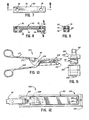
- Figure 10 is a side view of an instrument for applying the first embodiment of the fastener illustrated in Figures 1-9;
- Figure 11 is a greatly enlarged, fragmentary, front end view of the instrument illustrated in Figure 10;
- Figure 12 is a greatly enlarged, fragmentary, top plan view of the instrument of Figure 10;
- Figures 13-16 are greatly enlarged, fragmentary, partial cross-sectional views of the instrument of Figure 10 illustrating the sequence of operation of the instrument;
- Figure 17 is a greatly enlarged, fragmentary plane view of the instrument lower jaw taken along the plane 17-17 in Figure 13;
- Figure 18 is a greatly enlarged, fragmentary, cross-sectional view of'the front end of the jaws of the instrument in the closed position shown in Figure 16;
- Figure 19 is a fragmentary, cross-sectional view similar to Figure 18 but limited to the end of the lower jaw and showing a modified form of the instrument;
- Figure 20 is a fragmentary, partial, cross-sectional view of a second embodiment of the fastener shown in an orientation similar to that of the orientation of the first embodiment of the fastener in Figure 2;
- Figure 21 is a fragmentary, cross-sectional view taken generally along the plane 21-21 in Figure 20;
- Figure 22 is a side view of the receiver of the second embodiment of the fastener shown in Figures 20 and 21;
- Figure 23 is a top plan view of the receiver of the second embodiment of the fastener of Figures 20-22;
- Figure 24 is a cross-sectional view taken generally along the plane 24-24 in Figure 22;
- Figure 25 is a fragmentary, partial, cross-sectional view of a third emhodiment of the fastener shown in an orientation similar to that of the orientation of the first embodiment of the fastener in Figure 2;
- Figure 26 is a fragmentary, cross-sectional view taken generally along the plane 26-26 in Figure 25;
- Figure 27 is a side view of the receiver of the third embodiment of the fastener of Figures 25 and 26;
- Figure 28 is a top plan view of the third fastener embodiment receiver of Figures 25-27; and
- Figure 29 is a cross-sectional view taken generally along the plane 29-29 in Figure 27.
- This invention may be used in many different forms. The specification and the accompanying drawings disclose only a few specific forms as an example of the use of the invention. The precise shapes and sizes of the components herein described are not essential to the invention unless otherwise indicated. The invention is not intended to be limited to the embodiments illustrated, and the scope of the invention will be pointed out in the appended claims.
- A first embodiment of the fastener is illustrated in an assembled configuration in Figures 1-4 and is generally indicated therein by
reference numeral 50. Individual parts of the fastener are shown in Figures 5-9. - The plurality of
such fasteners 50 are illustrated in Figure 1 as holding together separatedportions - The fastener includes two components, a generally U-shaped or open
loop fastening member 60 and areceiver 62 which are initially separated as illustrated in Figure 4 which are adapted to cooperate to compress or hold between them thetissue portions - As is best illustrated in Figure 4, the
fastening member 60 includes 1) a pair oflegs 66 adapted to penetrate the tissue portions and 2) alink 68 which is connected to thelegs 66 and which is adapted to lie substantially against one of the tissue portions (e.g.,tissue portion 54 in Figure 2). Thelegs 66 of the fastening member are generally parallel to each other and are generally perpendicular to thelink 68. Preferably, eachleg 66 has a solid, generally cylindrical configuration with a conical end 70 (Figures 4-6) to facilitate or aid in the penetration of the tissue portions. Thelink 68 may have the regular parallelpiped shape illustrated or may have any other suitable shape. - As best illustrated in Figures 7-9, the
receiver 62 includes acentral member 72 joining a pair ofleg receiving members 74. Eachleg receiving member 74 defines at least onepassage 76 for receiving one of thefastening member legs 66 as best illustrated in Figure 3. If thefastening member legs 66 have a cylindrical configuration as illustrated, then the receivingmember passages 76 are preferably cylindrical bores of sufficient diameter to permit thelegs 66 to be received (loosely or in sliding engagement). Each receivingmember 74 and thepassage 76 defined therein cooperate as means for receiving and encompassing at least a portion of one of thefastening member legs 66 after the leg has been inserted through the tissue portions as best illustrated in Figures 2 and 3. - Preferably, each receiving
member 74 of thereceiver 62 defines a first aperture 78 (Figures 3 and 9) communicating from the exterior of the receivingmember 74 with the interior of thepassage 76. Also, a second aperture 80 (Figures 3 and 9) is provided in the receivingmember 74 opposite thefirst aperture 78 for communicating between the exterior of the receivingmember 74 and the interior of thepassage 76. At least one of these twoapertures fastening member leg 66 in a manner described in detail hereinafter. The other of theapertures receiver 62 within the instrument in a manner also described in detail hereinafter. - The
fastening member 60 and thereceiver 62 may be formed from suitable materials, such as thermoplastic polymer materials that are absorbable by mammalian tissue. For example, thefastening member 60 has been satisfactorily molded from a copolymer of lactide and glycolide. Preferably, thefastening member 60 is molded in a heated mold, is post-scoured, and is annealed. - According to the novel method of joining tissue portions with the above-described
fastener 50, thetissue portions 52 and 54 (Figures 1-3) are approximated in surface-to-surface relationship. Thefastening member 60 is then positioned on one side of the tissue portions with thelegs 66 oriented at an appropriate angle to penetrate the tissue portions. Thereceiver 62 is held on the other side of the tissue portions opposite thefastening member 60 and generally in alignment with thefastening member legs 66. Specifically, thepassages 76 are aligned with thefastening member legs 66. - Next, relative movement between the fastening
member 60 and thereceiver 62 is effected to urge the fastening member and the receiver closer together to cause thefastening member legs 66 to penetrate thetissue portions fastening member legs 66 within thereceiver 62. The relative movement between the fasteningmember 60 and the receiver 6a is terminated when thefastening member link 68 is at a desired distance from thereceiver 62 to secure the tissue portions together. Preferably, this movement is terminated after the tissue portions have been compressed together a desired amount. - At this point, the distal ends of the
fastening member legs 66 will typically protrude from the receiver opposite the side of the receiver that is contacting one of the tissue portions. In Figures 1-2, thelegs 66 are not shown protruding beyond thereceiver 62 since, in accordance with a preferred further step of the method, the protruding portions bave been severed flush with thereceiver 62. An instrument for applying thefastener 50 and severing thelegs 66 is described in detail hereinafter. However, in its broadest form, the method of applying thefastener 50 to the tissue portions does not necessarily require the severance of the protruding portions of thefastening member legs 66. - Regardless of whether or not the protruding portions of the
fastening member legs 66 are severed, thefastening member legs 66 and/or thereceiver 62 are acted upon in a certain manner to effect an engagement of thelegs 66 with thereceiver 62 to hold the two tissue portions together. To this end, in a preferred form of the method, each fasteningmember leg 66 is deformed or coined to force a bulged outportion 79 of each fasteningmember leg 66 into engagement with thereceiver 62. - Specifically, as best illustrated in Figures 2 and 3, a force may be applied by means of a tool or instrument through one or both.of the
apertures receiver 62 and against a-portion of each leg. 66. The amount of force is such that the pressure on eachleg 66 deforms aportion 79 of the leg material outwardly into either end of one or both of theapertures - To accommodate this bulging out of the
leg portion 79, theapertures apertures cylindrical bore passage 76. This accommodates the bulged outportion 79 of the'fastening member leg material and thus effects a rivet-like engagement of theleg 66 with thereceiver 62. - It has been found that the above-described method of applying the
fastener 50 to the tissue portions results in a relatively strong retention structure comprising thefastening member 60 and engagedreceiver 62. Further, onesize fastener 50 may be used for a variety of different tissue thicknesses since thefastening member 60 can be inserted into thereceiver 62 to the desired depth and thelegs 66 can then be deformed to effect the engagement of the legs and receiver with the desired amount of tissue compression. This deformation can take place at any point along the length of eachleg 66, depending on tissue thickness. Such a fastener structure and method of applying the fastener readily accommodate application of thefastener 50 by means of a suitable instrument that can be designed to apply a plurality of such fasteners simultaneously. - With the embodiment of the
fastener 50 described above, thelegs 66 are deformed into engagement with thereceiver 62. However, it is to be understood that thelegs 66 may be formed with apertures or notches (not illustrated) and that portions of thereceiver 62 may be deformed into the leg notches or apertures for effecting the engagement .between thereceiver 62 andfastening member 60. Further, a combination of both the deformation of thereceiver 62 and the deformation of thelegs 66 may also be used to effect engagement of thereceiver 62 andfastening member 60. - With the above-described method, the protruding portions of the
fastening member legs 66 may be severed during or after the step of deforming thelegs 66 and/orreceiver 62. Preferably, during the step of severing the protruding portions of thefastening member legs 66, the protruding portions of the fastening member legs are surrounded with a suitable container for catching the leg protruding portions after they are severed so as to prevent the severed portions of legs from falling into the surrounding tissue or body cavity. - The material from which the fastening member legs.66 are formed is preferably selected to accommodate the deforming action. To this end, copolymers of lactide and glycolide have been found to work satisfactorily. If just the legs are to be deformed, the
receiver 62 need not be fabricated from such a relatively easily deformable material. On the other hand, the copolymers of lactide and glycolide may be made relatively inelastic enough to function well as a receiver also even if it is not intended that the receiver be deformed. - Regardless of the materials selected for the
fastening member 60 andreceiver 62, it may be desirable to effect the method of deforming thefastening legs 66 and/orreceiver 62 with the aid of heat to soften the material. Such heat may be provided by a suitable process (e.g., electrical resistance heating). Such heating would reduce the magnitude of the mechanical forces required to effect the necessary deformation. - A tool or instrument for applying the first embodiment of the
fastener 50 is illustrated in Figures 10-19 and is designated generally by thereference numeral 100. As is best illustrated in Figures 10, 11, and 12, the instrument includes afirst jaw 101 for holding thefastening member 60 on one side of the tissue portions with thefastening member legs 66 oriented at an appropriate angle to penetrate thetissue portions instrument 100 further includes asecond jaw 102 for holding thereceiver 62 on the other side of the tissue portions opposite thefastening member 60 and generally in alignment with thefastening member legs 66. - The
first jaw 101 andsecond jaw 102 are pivotally mounted together about apin 104. Also pivotally mounted to pin 104 is a fasteningmember driving frame 106 which functions as a means for moving thefastening member 60 relative to thefirst jaw 101 to penetrate thetissue portions legs 66 of the fastening member and to locate at least portions of thefastening member legs 66 within thereceiver 62 held in thesecond jaw 102. - A first scissors-type-
handle lever 108 extends rearwardly from the drivingframe 106. Therefore, the fastening member moving means or drivingframe 106 can be regarded as being mounted to, and extending forwardly from, thefirst handle lever 108. Thefirst handle lever 108 defines a "Y" configuration where it is joined to thedriving frame 106. At this point, the front end of thehandle lever 108 defines anengaging surface 109 for engaging the lower exterior portion of thesecond jaw 102 when thejaws - A second scissors-
type handle 110 is pivotally mounted about apin 112 to the upper rear portion of thesecond jaw 102. Thesecond jaw 102 can be alternatively regarded as being pivotally mounted to, and extending from, thesecond handle lever 110. Both handlelevers - As best illustrated in Figure 13, the
second handle lever 110 is biased outwardly from thefirst handle lever 108 by means of a helical compression spring 114 (Figure 13). Thespring 114 is disposed within abore 116 in the upper rear portion of thesecond jaw 102 and bears upwardly against an annular bearing ring orplate 118 which is secured to the underside of thesecond handle lever 110. - As best illustrated in Figure 13, the
first jaw 101 is mounted to thepin 104 in the manner that permits thefirst jaw 101 to move relative to both the fasteningmember driving frame 106 and thesecond jaw 102. Thefirst jaw 101 is adapted to cooperate with the fasteningmember driving frame 106 as best illustrated in Figures 12 and 14. Specifically, the front end of thejaw 101 defines a passage in the form of a T-shapedslot 120 for receiving thefastening member 60 for receiving a generally T-shapedpusher member 122. - As best illustrated in Figures 13 and 14, the crosswise portion of the T-shaped slot or
passage 120 functions as a channel for frictionally receiving thefastening member 60 and the cross bar portion of thepusher member 122. The base of thepusher member 122 extends out of theslot 120 and is slidably disposed within an aperture 3.26 at the front of the fasteningmember driving frame 106 as best illustrated in Figure 18. This mounting of thepusher member 122 in theframe 106 facilitates entry of thepusher member 122 into the T-shapedslot 120 of thefirst jaw 101. - The
pusher member 122 preferably includes an upwardly projecting tab 123 (Figure 13) to retain thepusher member 122 within the fasteningmember driving frame 106 when theframe 106 is tilted upwardly in the orientation shown in Figure 13. - The
second jaw 102 holds thefastener receiver 62 in aslot 127 as best illustrated in Figure 14 and houses the fastening member leg deforming and severing mechanism as is next explained in detail. Thelower jaw 102 includes a generallycylindrical anvil member 130 slidably disposed within acylindrical bore 132 and biased outwardly a predetermined amount by means of ahelical spring 134. The distal end of theanvil 130 has a curved or somewhat hemispherical configuration adapted to enter into one of thereceiver apertures 78 or 80 (Figure 9) to vertically position thereceiver 62 within thesecond jaw 102. Lateral positioning of thereceiver 62 in thesecond jaw 102 is effected by the four walls defining theslot 127 in thelower jaw 102. - To accommodate the insertion of the
receiver 62 into thesecond jaw 102, the bottom of thereceiver 62 is preferably rounded so as.-to tangentially engage the hemispherical end of theanvil member 130 and cause theanvil member 130 to be pushed rearwardly against thespring 134 until thereceiver apertures anvil member 130. At this point, theanvil member 130 is biased outwardly into one of the receiver apertures to fix the vertical position of thereceiver 62 in thesecond jaw 102. - As best illustrated in Figures 13, 17, and 18, a pair of deforming
members 150 are mounted for movement within thesecond jaw 102. Preferably, as best illustrated in Figures 13-17, the deformingmembers 150 are part of a unitaryreciprocative actuating member 154 which is slidably disposed in a receiving cavity 156 (Figures 16 and 18) in thesecond jaw 102. - Also unitary with the
reciprocative actuating member 154 are two cuttingblades 160 which are spaced below, and in alignment with, the deformingmembers 150. - A novel means is provided for moving the deforming
members 150 and thecutting blades 160 forwardly into the fastener. Specifically, thereciprocative actuating member 154 includes aflexible drive member 170 extending rearwardly in anarcuate channel 172 in thesecond jaw 102. Theflexible drive member 170 includes adisk 174 at its distal end which is received in acylindrical bore 176 defined in thesecond handle lever 110. - Normally, when the handle levers 108 and 110 are in the unactuated, open position illustrated in Figure 13, the
spring 114 biases the handle levers 108 and 110 apart so that theannular ring 118 secured to thesecond handle lever 110 pulls up on thedisk 174, and hence pulls the attachedflexible drive member 170 upwardly and rearwardly relative to the front of the instrument. This causes thereciprocative actuating member 154 to be pulled rearwardly in its receivingcavity 156 to the fully retracted position illustrated in Figure 13. - On the other hand, when the handle levers 108 and 110 are closed in the orientation illustrated in Figure 16,
disk 174 is moved downwardly by thesecond handle lever 110 to force thedrive member 170, and hence the actuatingmember 154, forwardly to the extended position illustrated in Figures 16 and 18. The resulting action of the deformingmembers 150 andblades 160 on the fastener is described in detail hereinafter. - As best illustrated in Figure 13, the
second handle lever 110 is preferably provided with a pair of depending skirts 177 (one of which is visible in Figure 10 and the other of which is visible in Figure 13) to inhibit access to theflexible drive member 170 andspring 114. Also, as best illustrated in Figure 13, the upper rear portion of thesecond jaw 102 defines aflat abutment surface 180 between theskirts 177 for cooperating with the underside of thesecond handle lever 110 to limit the movement of thesecond handle lever 110 relative to thesecond jaw 102 and, hence, relative to thefirst handle lever 108. This, of course, limits the forward travel of thereciprocative actuating member 154 to the positon illustrated in Figure 16. - In operation, the tool is initially oriented as illustrated in Figure 13 with the
first jaw 101 and thesecond jaw 102 temporarily held apart to permit the insertion of thereceiver 62 into theslot 127 of thelower jaw 102. When properly inserted, the receiver is engaged as described above by theanvil member 130. - Next, the
fastening member 60 is inserted in thedriving frame channel 120 as illustrated in Figures 13 and 14. Then, as illustrated in Figure 14, thefirst jaw 101 and thesecond jaw 102 are disposed on either side of thetissue portions first handle lever 108 is pulled toward thesecond handle lever 110 to bring thepusher member 122 on top of thefastening member 60 and into thechannel 120. Initially, thesecond handle lever 110 does not pivot relative to thesecond jaw 102 because the force applied to thehandle lever 110 is not great enough to overcome the force ofspring 114. Consequently, relative movement occurs between the drivingframe 106 and thesecond jaw 102 so that thepusher member 122 forces the fasteningmember 60 through thetissue portions receiver 62. - In the instrument embodiment illustrated in Figures 13-16, the downward movement of the
pusher member 122 terminates when the drivingframe 106 pivots to the orientation illustrated in Figure 15. At this point, the engagingsurface 109 of thefirst handle lever 108 engages the bottom exterior surface of thesecond jaw 102 and prevents a further pivoting of theframe 106 andsecond jaw 102 about thepin 104. This precludes undue compression of thetissue portions second jaw 102 by thefirst handle lever 108 may not be necessary in some situations and that no limitation of the downward movement of thepusher member 122 need necessarily be provided. - If the
engaging surface 109 is provided on thehandle 108 for engaging thesecond jaw 102, then further movement of thefirst handle lever 108 towards thesecond handle lever 110 is prohibited when thefirst handle lever 108 reaches the orientation illustrated in Figure 15. At this point, any further force applied to squeeze the two together handlelevers spring 114 and to cause thesecond handle lever 110 to pivot about thepin 112. This drives thereciprocative actuating member 154 forward to the position illustrated in Figure 16. - When the
second handle lever 110 engages thetop surface 180 of the rear portion of thesecond jaw 102, further forward movement of thereciprocative actuating member 154 is necessarily prevented. At this point, the deformingmembers 150 have become positioned within the apertures (78 or 80 in Figure 9) of the receivingmember 62 and have deformed a portion of each of thefastening member legs 66 to thereby effect an engagement of thefastening member legs 66 andreceiver 62 in the manner described in detail above with respect to Figures 1-9. - Similarily, when the actuating
member 154 is in the extended position as illustrated in Figure 16, the spaced-apartcutting blades 160 have moved across the bottom of thereceiver 62 to sever the protruding portions of thelegs 66 from thefastening member 60 at substantially the same time the legs are being deformed into engagement with thereceiver 62 bymembers 150 . Preferably, thecutting blades 160 are arranged to sever the protruding portions of the legs flush with the bottom of the receiver so as to eliminate the possiblity of protrusions that could injure surrounding tissue. - Even if the
engagement surface 109 is not provided as part of thefirst handle lever 108 and associatedframe 106, theinstrument 100 will function in the same manner as just described. Specifically, even though the downward movement of thepusher member 122 is not terminated by mechanical engagement of interacting parts of the instrument, the force required to compress thetissue portions member link 68 and thesecond jaw 102 eventually becomes so great that thespring 114 is overcome and thesecond handle 110 pivots to the position illustrated in Figure 16 to effect the deformation of thefastening member legs 66 and the severance of the protruding portions of the legs. - If desired, the
instrument 100 may be provided with means for heating the deformingmembers 150. Although not illustrated, such heating means could include electrical resistance heating elements powered by a suitable battery. Heating of the deformingmembers 150 would reduce the amount of force required to cause deformation of the fastener leg material. - After the
fastener 50 has been applied as illustrated in Figure 18, the handle levers 108 and 110 are opened. Thesecond jaw 102 can be disengaged from thereceiver 62 by pulling thesecond jaw 102 away from the receiver 62 (which is now secured to the tissue with the fastening member 60). It is possible to disengage thesecond jaw 102 from thereceiver 62 because the curved distal end of theanvil 130 in thesecond jaw 102 will be forced further into the receivingcavity 132 and out of the receiver aperture as thesecond jaw 102 is pulled downwardly past the bottom of thereceiver 62. - Figure 19 illustrates a modification of the
instrument 100 shown in Figures 10-18. Specifically, a cage, housing, orcontainer 192 is provided at the bottom of thesecond jaw 102 for receiving the severed portions of thefastening member legs 66. This prevents the severed portions of the legs from falling into the body cavity. Thehousing 192 can be designed so it is readily movable from thesecond jaw 102 when desired for disposing of the severed leg portions. - Although the
instrument 100 has been illustrated as being designed to deform the fastening member legs into engagement with the receiver substantially simultaneously with the step of severing the protruding ends of the legs, it is to be realized - that the step of severing the legs may be effected before or after the deformation step. - Further, although the
instrument 100 preferably includes thecutting blades 160 for severing the projecting portions of thelegs 66 as described above, in some applications it may not be desired to sever the legs. In such applications, thecutting blades 160 may, of course, be omitted from the instrument if desired. - Although the
instrument 100 has been illustrated as designed for applying one fastener at a time, it is to be realized that the instrument may be modified to apply a plurality of fasteners simultaneously. For example, the jaws could be made considerably wider and could be provided with a plurality ofcavities 132 andpassages 120 for holding thereceivers 62 andfastening members 60, respectively, and with a plurality ofpusher members 122. - The second embodiment of the fastener is illustrated in Figures 20-24 and is designated generally by the
reference numeral 50A. The elements of thesecond embodiment 50A that are identical or functionally analogous to those of thefirst embodiment 50 are designated by reference numerals identical to those used for the first embodiment with the exception that the second embodiment reference numerals are followed by the upper case letter A whereas the first embodiment reference numerals are not followed by any letter.' - The
fastener 50A has ah open loop orU-shaped fastening member 60A withlegs 66A substantially identical to thefastening member 60 of the first embodiment described above with reference to Figures 1-9. - The
fastener 50A also includes areceiver 62A which is similar to thereceiver 62 of the first embodiment of thefastener 50 described above with reference to Figures 1-9. Thereceiver 62A hascentral member 72A joining a pair ofleg receiving members 74A. Eachleg receiving member 74A defines a generallycylindrical bore 76A for receiving one of thefastening member legs 66A. - Further, each receiving
member 74A defines oneaperture 78A communicating between the exterior of the receiving member and the interior of thebore 76A. Unlike thereceiver 62 of the first embodiment of thefastener 50 described above with reference to Figures 1-9, the receiver 62A.does not have a second aperture opposite theaperture 78A. Theaperture 78A functions to admit a deforming member of a suitable instrument that is used in applying thefastener 50A to tissue portions. The deforming member of the instrument would pass through theaperture 78A and deform theleg 66A to produce a bulged outportion 79A (Figure 20). To accommodate the bulged outportion 79A, theaperture 78A has a dimension (as measured in the direction normal to the longitudinal axis of the fastening member leg) which is larger than the diameter of the leg receiving bore 76A. Thus, the bulged outportion 79A acts to retain thefastening member 60A in thereceiver 62A. - The second embodiment of the
fastening member 50A may be applied with a suitable instrument similar to theinstrument 100 described above with reference to Figures 10-19. However, such an instrument would not require the spring biased anvil (anvil 130 illustrated in Figure 18). Other suitable means for temporarily aligning thereceiver 62A vertically within the instrument lower jaw would be provided. - A third embodiment of the fastener is illustrated in Figures 25-29 wherein the fastener is designated generally by
reference numeral 50B. The elements of the third embodiment of thefastener 50B that are identical or functionally anaglous to those of the first embodiment of thefastener 50 are designated by reference numerals identical to those used for the first embodiment with the exception that the third embodiment reference numerals are followed by the upper case letter B whereas no letter follows the first embodiment reference numerals. - The third embodiment of the
fastening member 50B includes a generallyU-shaped fastening member 60B that is substantially identical, in the unapplied condition, to thefastening member 60 of the first embodiment of thefastener 50 described above with reference to Figures 1-9. The third embodiment of thefastener 50B also includes areceiver 62B that includes acentral member 72B joining a pair ofleg receiving members 74B. Eachleg receiving member 74B defines at least one passage, such as acylindrical bore 76, for receiving one of thefastening member legs 66B. - The height of each
leg receiving member 74B is less than the height of eachleg receiving member 74 of the first embodiment of thefastener 50 described above with reference to Figures l-9. Further, no apertures (such asapertures receiver 62 of the first embodiment of thefastener 50 illustrated in Figures 1-4) are provided. Rather, thelegs 66B are deformed, as by producing abulge 79B (Figure 25), adjacent the side of thereceiver 62B that faces away from, thetissue portion - The deformation of the
fastening member legs 66B may be effected with a instrument similar to theinstrument 100 described above with reference to Figures 10-19. However, the springbiased anvil 130 of the instrument 100 (Figure 18) need not be provided. Rather, a fixed anvil may be provided in such an instrument immediately below the bottom of the receiver. In addition, the cutter blades (such ascutter blades 160 of theinstrument 100 illustrated in Figure 18) would be spaced below the bottom of thereceiver 62B by an amount sufficient to accommodate thedeformed portion 79B of the fastening member legs. - Although not illustrated, the fastener design may also include an interference fit or friction fit feature. For example, the fastening member legs may be provided with protrusions for engaging suitable portions of the receiver. The friction fit would provide a retention restraint in addition to the restraint provided by the permanent deformation of the legs and/or receiver.
- In the figures, the two legs of the fastening member are connected by a portion of the fastening member (e.g., the link or clamping member) which is illustrated as being generally straight and extending perpendicular to the two legs. The structure need not be limited to such a shape however. Instead, all or a portion of the length of the fastening member between the-two legs may be arched or arcuate or may include an arcuate portion (e.g., an inverted U-shaped configuration). This would function to initially provide a free space between the upper tissue portion and the top of the fastening member to allow for some expansion of the tissue.
- However, in those situations where increased initial tissue compression is desired, a modified receiver structure may be provided to cooperate with the above-described arcuate fastening member. Specifically, the receiver need not have a flat upper surface as illustrated. Rather, the upper surface of the receiver may be arcuate (e.g., convex) so as to generally match or correspond with the arcuate shape of the fastening member. This can result in an increased compression of the two tissue portions between the receiver and fastening member.
- From the foregoing, it will be observed that numerous variations and modifications may be effected without departing from the true spirt and scope of the novel concept of the invention. It is to be understood that no limitation with respect to the specific articles, instruments, and methods illustrated herein is intended or should be inferred. It is, of course, intended to cover by the appended claims all such modifications as fall within the scope of the claims.
Claims (18)
Applications Claiming Priority (2)
| Application Number | Priority Date | Filing Date | Title |
|---|---|---|---|
| US506151 | 1983-06-20 | ||
| US06/506,151 US4573469A (en) | 1983-06-20 | 1983-06-20 | Two-piece tissue fastener with coinable leg staple and retaining receiver and method and instrument for applying same |
Publications (2)
| Publication Number | Publication Date |
|---|---|
| EP0129441A1 true EP0129441A1 (en) | 1984-12-27 |
| EP0129441B1 EP0129441B1 (en) | 1987-11-19 |
Family
ID=24013406
Family Applications (1)
| Application Number | Title | Priority Date | Filing Date |
|---|---|---|---|
| EP84304132A Expired EP0129441B1 (en) | 1983-06-20 | 1984-06-19 | Two-piece tissue fastener with coinable leg staple and retaining receiver and method and instrument for applying same |
Country Status (9)
| Country | Link |
|---|---|
| US (1) | US4573469A (en) |
| EP (1) | EP0129441B1 (en) |
| JP (1) | JPS6012046A (en) |
| AU (1) | AU565190B2 (en) |
| BR (1) | BR8403004A (en) |
| CA (1) | CA1259875A (en) |
| DE (1) | DE3467501D1 (en) |
| GR (1) | GR81918B (en) |
| ZA (1) | ZA844641B (en) |
Cited By (3)
| Publication number | Priority date | Publication date | Assignee | Title |
|---|---|---|---|---|
| EP0169044A2 (en) * | 1984-07-16 | 1986-01-22 | Ethicon, Inc. | "W" shaped staples and slotted receivers |
| US4671280A (en) * | 1985-05-13 | 1987-06-09 | Ethicon, Inc. | Surgical fastening device and method for manufacture |
| US6149658A (en) * | 1997-01-09 | 2000-11-21 | Coalescent Surgical, Inc. | Sutured staple surgical fasteners, instruments and methods for minimally invasive vascular and endoscopic surgery |
Families Citing this family (560)
| Publication number | Priority date | Publication date | Assignee | Title |
|---|---|---|---|---|
| US4741336A (en) * | 1984-07-16 | 1988-05-03 | Ethicon, Inc. | Shaped staples and slotted receivers (case VII) |
| US5100418A (en) | 1987-05-14 | 1992-03-31 | Inbae Yoon | Suture tie device system and applicator therefor |
| US4932962A (en) * | 1989-05-16 | 1990-06-12 | Inbae Yoon | Suture devices particularly useful in endoscopic surgery and methods of suturing |
| US5222976A (en) * | 1989-05-16 | 1993-06-29 | Inbae Yoon | Suture devices particularly useful in endoscopic surgery |
| US5053047A (en) * | 1989-05-16 | 1991-10-01 | Inbae Yoon | Suture devices particularly useful in endoscopic surgery and methods of suturing |
| US5395391A (en) * | 1993-06-07 | 1995-03-07 | Essig; Mitchell N. | Method for closing ressected uterine tissues |
| US5391173A (en) * | 1994-02-10 | 1995-02-21 | Wilk; Peter J. | Laparoscopic suturing technique and associated device |
| US5904697A (en) * | 1995-02-24 | 1999-05-18 | Heartport, Inc. | Devices and methods for performing a vascular anastomosis |
| US6551328B2 (en) * | 1997-11-03 | 2003-04-22 | Symbiosis Corporation | Surgical instrument for invagination and fundoplication |
| US6086600A (en) | 1997-11-03 | 2000-07-11 | Symbiosis Corporation | Flexible endoscopic surgical instrument for invagination and fundoplication |
| US6641593B1 (en) | 1998-06-03 | 2003-11-04 | Coalescent Surgical, Inc. | Tissue connector apparatus and methods |
| US6945980B2 (en) | 1998-06-03 | 2005-09-20 | Medtronic, Inc. | Multiple loop tissue connector apparatus and methods |
| US6613059B2 (en) | 1999-03-01 | 2003-09-02 | Coalescent Surgical, Inc. | Tissue connector apparatus and methods |
| US8118822B2 (en) | 1999-03-01 | 2012-02-21 | Medtronic, Inc. | Bridge clip tissue connector apparatus and methods |
| US6981983B1 (en) | 1999-03-31 | 2006-01-03 | Rosenblatt Peter L | System and methods for soft tissue reconstruction |
| US20050283189A1 (en) * | 1999-03-31 | 2005-12-22 | Rosenblatt Peter L | Systems and methods for soft tissue reconstruction |
| US6695859B1 (en) | 1999-04-05 | 2004-02-24 | Coalescent Surgical, Inc. | Apparatus and methods for anastomosis |
| US7846180B2 (en) | 1999-06-22 | 2010-12-07 | Ethicon Endo-Surgery, Inc. | Tissue fixation devices and methods of fixing tissue |
| US8287554B2 (en) * | 1999-06-22 | 2012-10-16 | Ethicon Endo-Surgery, Inc. | Method and devices for tissue reconfiguration |
| US6663639B1 (en) | 1999-06-22 | 2003-12-16 | Ndo Surgical, Inc. | Methods and devices for tissue reconfiguration |
| US6494888B1 (en) * | 1999-06-22 | 2002-12-17 | Ndo Surgical, Inc. | Tissue reconfiguration |
| US6821285B2 (en) * | 1999-06-22 | 2004-11-23 | Ndo Surgical, Inc. | Tissue reconfiguration |
| US6835200B2 (en) | 1999-06-22 | 2004-12-28 | Ndo Surgical. Inc. | Method and devices for tissue reconfiguration |
| US8529583B1 (en) | 1999-09-03 | 2013-09-10 | Medtronic, Inc. | Surgical clip removal apparatus |
| US6926730B1 (en) | 2000-10-10 | 2005-08-09 | Medtronic, Inc. | Minimally invasive valve repair procedure and apparatus |
| US6551332B1 (en) | 2000-03-31 | 2003-04-22 | Coalescent Surgical, Inc. | Multiple bias surgical fastener |
| US6305891B1 (en) * | 2000-05-15 | 2001-10-23 | Mark S. Burlingame | Fastening device and a spacer, and a method of using the same |
| US6438924B1 (en) * | 2000-08-22 | 2002-08-27 | Edward N. Martin | Slot forming tool for wall construction |
| US6503259B2 (en) * | 2000-12-27 | 2003-01-07 | Ethicon, Inc. | Expandable anastomotic device |
| US20040126201A1 (en) * | 2002-08-09 | 2004-07-01 | Brian Kobylinski | Color-coded staples |
| US8066724B2 (en) | 2002-09-12 | 2011-11-29 | Medtronic, Inc. | Anastomosis apparatus and methods |
| US8105345B2 (en) | 2002-10-04 | 2012-01-31 | Medtronic, Inc. | Anastomosis apparatus and methods |
| US9060770B2 (en) | 2003-05-20 | 2015-06-23 | Ethicon Endo-Surgery, Inc. | Robotically-driven surgical instrument with E-beam driver |
| US20070084897A1 (en) | 2003-05-20 | 2007-04-19 | Shelton Frederick E Iv | Articulating surgical stapling instrument incorporating a two-piece e-beam firing mechanism |
| US7182769B2 (en) | 2003-07-25 | 2007-02-27 | Medtronic, Inc. | Sealing clip, delivery systems, and methods |
| US20050043749A1 (en) | 2003-08-22 | 2005-02-24 | Coalescent Surgical, Inc. | Eversion apparatus and methods |
| US8394114B2 (en) | 2003-09-26 | 2013-03-12 | Medtronic, Inc. | Surgical connection apparatus and methods |
| US7118318B2 (en) * | 2003-11-20 | 2006-10-10 | Bellsouth Intellectual Property Corporation | Wire protector and retainer |
| US7128761B2 (en) * | 2003-12-10 | 2006-10-31 | Axiomed Spine Corporation | Method and apparatus for replacing a damaged spinal disc |
| US7879047B2 (en) | 2003-12-10 | 2011-02-01 | Medtronic, Inc. | Surgical connection apparatus and methods |
| US20060015144A1 (en) * | 2004-07-19 | 2006-01-19 | Vascular Control Systems, Inc. | Uterine artery occlusion staple |
| US8215531B2 (en) | 2004-07-28 | 2012-07-10 | Ethicon Endo-Surgery, Inc. | Surgical stapling instrument having a medical substance dispenser |
| US11896225B2 (en) | 2004-07-28 | 2024-02-13 | Cilag Gmbh International | Staple cartridge comprising a pan |
| CA2549224A1 (en) * | 2005-06-02 | 2006-12-02 | Tyco Healthcare Group Lp | Expandable backspan staple |
| US7722610B2 (en) * | 2005-06-02 | 2010-05-25 | Tyco Healthcare Group Lp | Multiple coil staple and staple applier |
| US9237891B2 (en) | 2005-08-31 | 2016-01-19 | Ethicon Endo-Surgery, Inc. | Robotically-controlled surgical stapling devices that produce formed staples having different lengths |
| US11246590B2 (en) | 2005-08-31 | 2022-02-15 | Cilag Gmbh International | Staple cartridge including staple drivers having different unfired heights |
| US11484312B2 (en) | 2005-08-31 | 2022-11-01 | Cilag Gmbh International | Staple cartridge comprising a staple driver arrangement |
| US10159482B2 (en) | 2005-08-31 | 2018-12-25 | Ethicon Llc | Fastener cartridge assembly comprising a fixed anvil and different staple heights |
| US8800838B2 (en) | 2005-08-31 | 2014-08-12 | Ethicon Endo-Surgery, Inc. | Robotically-controlled cable-based surgical end effectors |
| US7934630B2 (en) * | 2005-08-31 | 2011-05-03 | Ethicon Endo-Surgery, Inc. | Staple cartridges for forming staples having differing formed staple heights |
| US20070194082A1 (en) | 2005-08-31 | 2007-08-23 | Morgan Jerome R | Surgical stapling device with anvil having staple forming pockets of varying depths |
| US7669746B2 (en) | 2005-08-31 | 2010-03-02 | Ethicon Endo-Surgery, Inc. | Staple cartridges for forming staples having differing formed staple heights |
| US20070106317A1 (en) | 2005-11-09 | 2007-05-10 | Shelton Frederick E Iv | Hydraulically and electrically actuated articulation joints for surgical instruments |
| US20070181756A1 (en) * | 2006-01-18 | 2007-08-09 | Gelfond-Holtz Alicia K | Transparent mounting strip |
| US11793518B2 (en) | 2006-01-31 | 2023-10-24 | Cilag Gmbh International | Powered surgical instruments with firing system lockout arrangements |
| US20110006101A1 (en) | 2009-02-06 | 2011-01-13 | EthiconEndo-Surgery, Inc. | Motor driven surgical fastener device with cutting member lockout arrangements |
| US20120292367A1 (en) | 2006-01-31 | 2012-11-22 | Ethicon Endo-Surgery, Inc. | Robotically-controlled end effector |
| US8186555B2 (en) | 2006-01-31 | 2012-05-29 | Ethicon Endo-Surgery, Inc. | Motor-driven surgical cutting and fastening instrument with mechanical closure system |
| US20110024477A1 (en) | 2009-02-06 | 2011-02-03 | Hall Steven G | Driven Surgical Stapler Improvements |
| US9861359B2 (en) | 2006-01-31 | 2018-01-09 | Ethicon Llc | Powered surgical instruments with firing system lockout arrangements |
| US8763879B2 (en) | 2006-01-31 | 2014-07-01 | Ethicon Endo-Surgery, Inc. | Accessing data stored in a memory of surgical instrument |
| US7845537B2 (en) | 2006-01-31 | 2010-12-07 | Ethicon Endo-Surgery, Inc. | Surgical instrument having recording capabilities |
| US8161977B2 (en) | 2006-01-31 | 2012-04-24 | Ethicon Endo-Surgery, Inc. | Accessing data stored in a memory of a surgical instrument |
| US20110295295A1 (en) | 2006-01-31 | 2011-12-01 | Ethicon Endo-Surgery, Inc. | Robotically-controlled surgical instrument having recording capabilities |
| US8708213B2 (en) | 2006-01-31 | 2014-04-29 | Ethicon Endo-Surgery, Inc. | Surgical instrument having a feedback system |
| US8820603B2 (en) | 2006-01-31 | 2014-09-02 | Ethicon Endo-Surgery, Inc. | Accessing data stored in a memory of a surgical instrument |
| US7753904B2 (en) | 2006-01-31 | 2010-07-13 | Ethicon Endo-Surgery, Inc. | Endoscopic surgical instrument with a handle that can articulate with respect to the shaft |
| US11224427B2 (en) | 2006-01-31 | 2022-01-18 | Cilag Gmbh International | Surgical stapling system including a console and retraction assembly |
| US11278279B2 (en) | 2006-01-31 | 2022-03-22 | Cilag Gmbh International | Surgical instrument assembly |
| US8992422B2 (en) | 2006-03-23 | 2015-03-31 | Ethicon Endo-Surgery, Inc. | Robotically-controlled endoscopic accessory channel |
| US20070225562A1 (en) | 2006-03-23 | 2007-09-27 | Ethicon Endo-Surgery, Inc. | Articulating endoscopic accessory channel |
| US8322455B2 (en) | 2006-06-27 | 2012-12-04 | Ethicon Endo-Surgery, Inc. | Manually driven surgical cutting and fastening instrument |
| US10130359B2 (en) | 2006-09-29 | 2018-11-20 | Ethicon Llc | Method for forming a staple |
| US10568652B2 (en) | 2006-09-29 | 2020-02-25 | Ethicon Llc | Surgical staples having attached drivers of different heights and stapling instruments for deploying the same |
| US7506791B2 (en) | 2006-09-29 | 2009-03-24 | Ethicon Endo-Surgery, Inc. | Surgical stapling instrument with mechanical mechanism for limiting maximum tissue compression |
| US8459520B2 (en) | 2007-01-10 | 2013-06-11 | Ethicon Endo-Surgery, Inc. | Surgical instrument with wireless communication between control unit and remote sensor |
| US11291441B2 (en) | 2007-01-10 | 2022-04-05 | Cilag Gmbh International | Surgical instrument with wireless communication between control unit and remote sensor |
| US8684253B2 (en) | 2007-01-10 | 2014-04-01 | Ethicon Endo-Surgery, Inc. | Surgical instrument with wireless communication between a control unit of a robotic system and remote sensor |
| US8652120B2 (en) | 2007-01-10 | 2014-02-18 | Ethicon Endo-Surgery, Inc. | Surgical instrument with wireless communication between control unit and sensor transponders |
| US8701958B2 (en) | 2007-01-11 | 2014-04-22 | Ethicon Endo-Surgery, Inc. | Curved end effector for a surgical stapling device |
| US11039836B2 (en) | 2007-01-11 | 2021-06-22 | Cilag Gmbh International | Staple cartridge for use with a surgical stapling instrument |
| RU2440150C2 (en) * | 2007-02-20 | 2012-01-20 | КейСиАй Лайсензинг Инк. | System and method of differentiating state of leak and state of reservoir disconnection in system of processing with lower pressure |
| US7669747B2 (en) | 2007-03-15 | 2010-03-02 | Ethicon Endo-Surgery, Inc. | Washer for use with a surgical stapling instrument |
| US20080234703A1 (en) * | 2007-03-23 | 2008-09-25 | Ethicon Endo-Surgery, Inc. | Tissue approximation system |
| US8852216B2 (en) | 2007-03-23 | 2014-10-07 | Ethicon Endo-Surgery, Inc. | Tissue approximation methods |
| US8893946B2 (en) | 2007-03-28 | 2014-11-25 | Ethicon Endo-Surgery, Inc. | Laparoscopic tissue thickness and clamp load measuring devices |
| WO2008137833A2 (en) * | 2007-05-07 | 2008-11-13 | Tyco Healthcare Group Lp | Variable size-uniform compression staple assembly |
| US8534528B2 (en) | 2007-06-04 | 2013-09-17 | Ethicon Endo-Surgery, Inc. | Surgical instrument having a multiple rate directional switching mechanism |
| US11564682B2 (en) | 2007-06-04 | 2023-01-31 | Cilag Gmbh International | Surgical stapler device |
| US8931682B2 (en) | 2007-06-04 | 2015-01-13 | Ethicon Endo-Surgery, Inc. | Robotically-controlled shaft based rotary drive systems for surgical instruments |
| US7832408B2 (en) | 2007-06-04 | 2010-11-16 | Ethicon Endo-Surgery, Inc. | Surgical instrument having a directional switching mechanism |
| US7905380B2 (en) | 2007-06-04 | 2011-03-15 | Ethicon Endo-Surgery, Inc. | Surgical instrument having a multiple rate directional switching mechanism |
| US8308040B2 (en) | 2007-06-22 | 2012-11-13 | Ethicon Endo-Surgery, Inc. | Surgical stapling instrument with an articulatable end effector |
| US7753245B2 (en) | 2007-06-22 | 2010-07-13 | Ethicon Endo-Surgery, Inc. | Surgical stapling instruments |
| US11849941B2 (en) | 2007-06-29 | 2023-12-26 | Cilag Gmbh International | Staple cartridge having staple cavities extending at a transverse angle relative to a longitudinal cartridge axis |
| US8348972B2 (en) * | 2007-07-11 | 2013-01-08 | Covidien Lp | Surgical staple with augmented compression area |
| US8561870B2 (en) | 2008-02-13 | 2013-10-22 | Ethicon Endo-Surgery, Inc. | Surgical stapling instrument |
| US7905381B2 (en) | 2008-09-19 | 2011-03-15 | Ethicon Endo-Surgery, Inc. | Surgical stapling instrument with cutting member arrangement |
| US8636736B2 (en) | 2008-02-14 | 2014-01-28 | Ethicon Endo-Surgery, Inc. | Motorized surgical cutting and fastening instrument |
| JP5410110B2 (en) | 2008-02-14 | 2014-02-05 | エシコン・エンド−サージェリィ・インコーポレイテッド | Surgical cutting / fixing instrument with RF electrode |
| US7866527B2 (en) | 2008-02-14 | 2011-01-11 | Ethicon Endo-Surgery, Inc. | Surgical stapling apparatus with interlockable firing system |
| US8573465B2 (en) | 2008-02-14 | 2013-11-05 | Ethicon Endo-Surgery, Inc. | Robotically-controlled surgical end effector system with rotary actuated closure systems |
| US8758391B2 (en) | 2008-02-14 | 2014-06-24 | Ethicon Endo-Surgery, Inc. | Interchangeable tools for surgical instruments |
| US8752749B2 (en) | 2008-02-14 | 2014-06-17 | Ethicon Endo-Surgery, Inc. | Robotically-controlled disposable motor-driven loading unit |
| US8584919B2 (en) | 2008-02-14 | 2013-11-19 | Ethicon Endo-Sugery, Inc. | Surgical stapling apparatus with load-sensitive firing mechanism |
| US7793812B2 (en) | 2008-02-14 | 2010-09-14 | Ethicon Endo-Surgery, Inc. | Disposable motor-driven loading unit for use with a surgical cutting and stapling apparatus |
| US8657174B2 (en) | 2008-02-14 | 2014-02-25 | Ethicon Endo-Surgery, Inc. | Motorized surgical cutting and fastening instrument having handle based power source |
| US7819298B2 (en) | 2008-02-14 | 2010-10-26 | Ethicon Endo-Surgery, Inc. | Surgical stapling apparatus with control features operable with one hand |
| US9179912B2 (en) | 2008-02-14 | 2015-11-10 | Ethicon Endo-Surgery, Inc. | Robotically-controlled motorized surgical cutting and fastening instrument |
| US8459525B2 (en) | 2008-02-14 | 2013-06-11 | Ethicon Endo-Sugery, Inc. | Motorized surgical cutting and fastening instrument having a magnetic drive train torque limiting device |
| US8622274B2 (en) | 2008-02-14 | 2014-01-07 | Ethicon Endo-Surgery, Inc. | Motorized cutting and fastening instrument having control circuit for optimizing battery usage |
| US11272927B2 (en) | 2008-02-15 | 2022-03-15 | Cilag Gmbh International | Layer arrangements for surgical staple cartridges |
| US20130153641A1 (en) | 2008-02-15 | 2013-06-20 | Ethicon Endo-Surgery, Inc. | Releasable layer of material and surgical end effector having the same |
| US8177836B2 (en) | 2008-03-10 | 2012-05-15 | Medtronic, Inc. | Apparatus and methods for minimally invasive valve repair |
| US8231040B2 (en) * | 2008-04-14 | 2012-07-31 | Tyco Healthcare Group Lp | Variable compression surgical fastener cartridge |
| US7926691B2 (en) | 2008-04-14 | 2011-04-19 | Tyco Healthcare Group, L.P. | Variable compression surgical fastener cartridge |
| US8100310B2 (en) * | 2008-04-14 | 2012-01-24 | Tyco Healthcare Group Lp | Variable compression surgical fastener apparatus |
| US20090255974A1 (en) * | 2008-04-14 | 2009-10-15 | Tyco Healthcare Group Lp | Single loop surgical fastener apparatus for applying variable compression |
| US8231041B2 (en) * | 2008-04-14 | 2012-07-31 | Tyco Healthcare Group Lp | Variable compression surgical fastener cartridge |
| US8277160B1 (en) * | 2008-04-29 | 2012-10-02 | Strauel Theodore A | Protective wire fastening apparatus |
| US8967446B2 (en) | 2008-05-09 | 2015-03-03 | Covidien Lp | Variable compression surgical fastener cartridge |
| US8091756B2 (en) | 2008-05-09 | 2012-01-10 | Tyco Healthcare Group Lp | Varying tissue compression using take-up component |
| US9016541B2 (en) | 2008-05-09 | 2015-04-28 | Covidien Lp | Varying tissue compression with an anvil configuration |
| US8464922B2 (en) | 2008-05-09 | 2013-06-18 | Covidien Lp | Variable compression surgical fastener cartridge |
| US8186556B2 (en) | 2008-05-09 | 2012-05-29 | Tyco Healthcare Group Lp | Variable compression surgical fastener apparatus |
| PL3476312T3 (en) | 2008-09-19 | 2024-03-11 | Ethicon Llc | Surgical stapler with apparatus for adjusting staple height |
| US11648005B2 (en) | 2008-09-23 | 2023-05-16 | Cilag Gmbh International | Robotically-controlled motorized surgical instrument with an end effector |
| US9386983B2 (en) | 2008-09-23 | 2016-07-12 | Ethicon Endo-Surgery, Llc | Robotically-controlled motorized surgical instrument |
| US9050083B2 (en) | 2008-09-23 | 2015-06-09 | Ethicon Endo-Surgery, Inc. | Motorized surgical instrument |
| US8210411B2 (en) | 2008-09-23 | 2012-07-03 | Ethicon Endo-Surgery, Inc. | Motor-driven surgical cutting instrument |
| US9005230B2 (en) | 2008-09-23 | 2015-04-14 | Ethicon Endo-Surgery, Inc. | Motorized surgical instrument |
| US8608045B2 (en) | 2008-10-10 | 2013-12-17 | Ethicon Endo-Sugery, Inc. | Powered surgical cutting and stapling apparatus with manually retractable firing system |
| US8381961B2 (en) * | 2009-01-14 | 2013-02-26 | Covidien Lp | Surgical stapling apparatus including staple with plate |
| US8397971B2 (en) | 2009-02-05 | 2013-03-19 | Ethicon Endo-Surgery, Inc. | Sterilizable surgical instrument |
| US8517239B2 (en) | 2009-02-05 | 2013-08-27 | Ethicon Endo-Surgery, Inc. | Surgical stapling instrument comprising a magnetic element driver |
| US8414577B2 (en) | 2009-02-05 | 2013-04-09 | Ethicon Endo-Surgery, Inc. | Surgical instruments and components for use in sterile environments |
| US8444036B2 (en) | 2009-02-06 | 2013-05-21 | Ethicon Endo-Surgery, Inc. | Motor driven surgical fastener device with mechanisms for adjusting a tissue gap within the end effector |
| EP2393430A1 (en) | 2009-02-06 | 2011-12-14 | Ethicon Endo-Surgery, Inc. | Driven surgical stapler improvements |
| US8518060B2 (en) | 2009-04-09 | 2013-08-27 | Medtronic, Inc. | Medical clip with radial tines, system and method of using same |
| US8292154B2 (en) * | 2009-04-16 | 2012-10-23 | Tyco Healthcare Group Lp | Surgical apparatus for applying tissue fasteners |
| US8668704B2 (en) | 2009-04-24 | 2014-03-11 | Medtronic, Inc. | Medical clip with tines, system and method of using same |
| US8851354B2 (en) | 2009-12-24 | 2014-10-07 | Ethicon Endo-Surgery, Inc. | Surgical cutting instrument that analyzes tissue thickness |
| US8220688B2 (en) | 2009-12-24 | 2012-07-17 | Ethicon Endo-Surgery, Inc. | Motor-driven surgical cutting instrument with electric actuator directional control assembly |
| US8783543B2 (en) | 2010-07-30 | 2014-07-22 | Ethicon Endo-Surgery, Inc. | Tissue acquisition arrangements and methods for surgical stapling devices |
| US9877720B2 (en) | 2010-09-24 | 2018-01-30 | Ethicon Llc | Control features for articulating surgical device |
| US8733613B2 (en) | 2010-09-29 | 2014-05-27 | Ethicon Endo-Surgery, Inc. | Staple cartridge |
| US9301753B2 (en) | 2010-09-30 | 2016-04-05 | Ethicon Endo-Surgery, Llc | Expandable tissue thickness compensator |
| US9277919B2 (en) | 2010-09-30 | 2016-03-08 | Ethicon Endo-Surgery, Llc | Tissue thickness compensator comprising fibers to produce a resilient load |
| US11849952B2 (en) | 2010-09-30 | 2023-12-26 | Cilag Gmbh International | Staple cartridge comprising staples positioned within a compressible portion thereof |
| US9216019B2 (en) | 2011-09-23 | 2015-12-22 | Ethicon Endo-Surgery, Inc. | Surgical stapler with stationary staple drivers |
| US10945731B2 (en) | 2010-09-30 | 2021-03-16 | Ethicon Llc | Tissue thickness compensator comprising controlled release and expansion |
| US8840003B2 (en) | 2010-09-30 | 2014-09-23 | Ethicon Endo-Surgery, Inc. | Surgical stapling instrument with compact articulation control arrangement |
| US9220501B2 (en) | 2010-09-30 | 2015-12-29 | Ethicon Endo-Surgery, Inc. | Tissue thickness compensators |
| US11812965B2 (en) | 2010-09-30 | 2023-11-14 | Cilag Gmbh International | Layer of material for a surgical end effector |
| US11298125B2 (en) | 2010-09-30 | 2022-04-12 | Cilag Gmbh International | Tissue stapler having a thickness compensator |
| US9629814B2 (en) | 2010-09-30 | 2017-04-25 | Ethicon Endo-Surgery, Llc | Tissue thickness compensator configured to redistribute compressive forces |
| US9386988B2 (en) | 2010-09-30 | 2016-07-12 | Ethicon End-Surgery, LLC | Retainer assembly including a tissue thickness compensator |
| US8893949B2 (en) | 2010-09-30 | 2014-11-25 | Ethicon Endo-Surgery, Inc. | Surgical stapler with floating anvil |
| US8746535B2 (en) | 2010-09-30 | 2014-06-10 | Ethicon Endo-Surgery, Inc. | Tissue thickness compensator comprising detachable portions |
| US9517063B2 (en) | 2012-03-28 | 2016-12-13 | Ethicon Endo-Surgery, Llc | Movable member for use with a tissue thickness compensator |
| US9566061B2 (en) | 2010-09-30 | 2017-02-14 | Ethicon Endo-Surgery, Llc | Fastener cartridge comprising a releasably attached tissue thickness compensator |
| US9307989B2 (en) | 2012-03-28 | 2016-04-12 | Ethicon Endo-Surgery, Llc | Tissue stapler having a thickness compensator incorportating a hydrophobic agent |
| US9332974B2 (en) | 2010-09-30 | 2016-05-10 | Ethicon Endo-Surgery, Llc | Layered tissue thickness compensator |
| US9314246B2 (en) | 2010-09-30 | 2016-04-19 | Ethicon Endo-Surgery, Llc | Tissue stapler having a thickness compensator incorporating an anti-inflammatory agent |
| US9414838B2 (en) | 2012-03-28 | 2016-08-16 | Ethicon Endo-Surgery, Llc | Tissue thickness compensator comprised of a plurality of materials |
| US9839420B2 (en) | 2010-09-30 | 2017-12-12 | Ethicon Llc | Tissue thickness compensator comprising at least one medicament |
| US9364233B2 (en) | 2010-09-30 | 2016-06-14 | Ethicon Endo-Surgery, Llc | Tissue thickness compensators for circular surgical staplers |
| EP2621356B1 (en) | 2010-09-30 | 2018-03-07 | Ethicon LLC | Fastener system comprising a retention matrix and an alignment matrix |
| US8695866B2 (en) | 2010-10-01 | 2014-04-15 | Ethicon Endo-Surgery, Inc. | Surgical instrument having a power control circuit |
| DE102012100086A1 (en) * | 2011-01-07 | 2012-08-02 | Z-Medical Gmbh & Co. Kg | Surgical instrument |
| US10398445B2 (en) | 2011-01-11 | 2019-09-03 | Amsel Medical Corporation | Method and apparatus for clamping tissue layers and occluding tubular body structures |
| US10820895B2 (en) | 2011-01-11 | 2020-11-03 | Amsel Medical Corporation | Methods and apparatus for fastening and clamping tissue |
| US20120260489A1 (en) * | 2011-04-18 | 2012-10-18 | Hamilton Elaine T | Button repair system and method |
| AU2012250197B2 (en) | 2011-04-29 | 2017-08-10 | Ethicon Endo-Surgery, Inc. | Staple cartridge comprising staples positioned within a compressible portion thereof |
| US9072535B2 (en) | 2011-05-27 | 2015-07-07 | Ethicon Endo-Surgery, Inc. | Surgical stapling instruments with rotatable staple deployment arrangements |
| US11207064B2 (en) | 2011-05-27 | 2021-12-28 | Cilag Gmbh International | Automated end effector component reloading system for use with a robotic system |
| JP5372192B2 (en) * | 2011-06-18 | 2013-12-18 | 須藤 二三男 | Wall mounting tool using plate-like pins |
| ES2633746T3 (en) * | 2011-07-18 | 2017-09-25 | Woodwelding Ag | Implant to stabilize each other separate bone portions |
| US9050084B2 (en) | 2011-09-23 | 2015-06-09 | Ethicon Endo-Surgery, Inc. | Staple cartridge including collapsible deck arrangement |
| US9044230B2 (en) | 2012-02-13 | 2015-06-02 | Ethicon Endo-Surgery, Inc. | Surgical cutting and fastening instrument with apparatus for determining cartridge and firing motion status |
| US9198662B2 (en) | 2012-03-28 | 2015-12-01 | Ethicon Endo-Surgery, Inc. | Tissue thickness compensator having improved visibility |
| RU2644272C2 (en) | 2012-03-28 | 2018-02-08 | Этикон Эндо-Серджери, Инк. | Limitation node with tissue thickness compensator |
| RU2639857C2 (en) | 2012-03-28 | 2017-12-22 | Этикон Эндо-Серджери, Инк. | Tissue thickness compensator containing capsule for medium with low pressure |
| MX358135B (en) | 2012-03-28 | 2018-08-06 | Ethicon Endo Surgery Inc | Tissue thickness compensator comprising a plurality of layers. |
| US9101358B2 (en) | 2012-06-15 | 2015-08-11 | Ethicon Endo-Surgery, Inc. | Articulatable surgical instrument comprising a firing drive |
| US9072536B2 (en) | 2012-06-28 | 2015-07-07 | Ethicon Endo-Surgery, Inc. | Differential locking arrangements for rotary powered surgical instruments |
| US20140001231A1 (en) | 2012-06-28 | 2014-01-02 | Ethicon Endo-Surgery, Inc. | Firing system lockout arrangements for surgical instruments |
| US8747238B2 (en) | 2012-06-28 | 2014-06-10 | Ethicon Endo-Surgery, Inc. | Rotary drive shaft assemblies for surgical instruments with articulatable end effectors |
| US9125662B2 (en) | 2012-06-28 | 2015-09-08 | Ethicon Endo-Surgery, Inc. | Multi-axis articulating and rotating surgical tools |
| US9561038B2 (en) | 2012-06-28 | 2017-02-07 | Ethicon Endo-Surgery, Llc | Interchangeable clip applier |
| US9649111B2 (en) | 2012-06-28 | 2017-05-16 | Ethicon Endo-Surgery, Llc | Replaceable clip cartridge for a clip applier |
| US9226751B2 (en) | 2012-06-28 | 2016-01-05 | Ethicon Endo-Surgery, Inc. | Surgical instrument system including replaceable end effectors |
| BR112014032776B1 (en) | 2012-06-28 | 2021-09-08 | Ethicon Endo-Surgery, Inc | SURGICAL INSTRUMENT SYSTEM AND SURGICAL KIT FOR USE WITH A SURGICAL INSTRUMENT SYSTEM |
| EP2866686A1 (en) | 2012-06-28 | 2015-05-06 | Ethicon Endo-Surgery, Inc. | Empty clip cartridge lockout |
| US9119657B2 (en) | 2012-06-28 | 2015-09-01 | Ethicon Endo-Surgery, Inc. | Rotary actuatable closure arrangement for surgical end effector |
| US9028494B2 (en) | 2012-06-28 | 2015-05-12 | Ethicon Endo-Surgery, Inc. | Interchangeable end effector coupling arrangement |
| US11202631B2 (en) | 2012-06-28 | 2021-12-21 | Cilag Gmbh International | Stapling assembly comprising a firing lockout |
| US9289256B2 (en) | 2012-06-28 | 2016-03-22 | Ethicon Endo-Surgery, Llc | Surgical end effectors having angled tissue-contacting surfaces |
| US9101385B2 (en) | 2012-06-28 | 2015-08-11 | Ethicon Endo-Surgery, Inc. | Electrode connections for rotary driven surgical tools |
| US20140005718A1 (en) | 2012-06-28 | 2014-01-02 | Ethicon Endo-Surgery, Inc. | Multi-functional powered surgical device with external dissection features |
| US9386984B2 (en) | 2013-02-08 | 2016-07-12 | Ethicon Endo-Surgery, Llc | Staple cartridge comprising a releasable cover |
| US10092292B2 (en) | 2013-02-28 | 2018-10-09 | Ethicon Llc | Staple forming features for surgical stapling instrument |
| RU2669463C2 (en) | 2013-03-01 | 2018-10-11 | Этикон Эндо-Серджери, Инк. | Surgical instrument with soft stop |
| RU2672520C2 (en) | 2013-03-01 | 2018-11-15 | Этикон Эндо-Серджери, Инк. | Hingedly turnable surgical instruments with conducting ways for signal transfer |
| US9358003B2 (en) | 2013-03-01 | 2016-06-07 | Ethicon Endo-Surgery, Llc | Electromechanical surgical device with signal relay arrangement |
| US9345481B2 (en) | 2013-03-13 | 2016-05-24 | Ethicon Endo-Surgery, Llc | Staple cartridge tissue thickness sensor system |
| US9629629B2 (en) | 2013-03-14 | 2017-04-25 | Ethicon Endo-Surgey, LLC | Control systems for surgical instruments |
| US9332987B2 (en) | 2013-03-14 | 2016-05-10 | Ethicon Endo-Surgery, Llc | Control arrangements for a drive member of a surgical instrument |
| US9332984B2 (en) | 2013-03-27 | 2016-05-10 | Ethicon Endo-Surgery, Llc | Fastener cartridge assemblies |
| US9795384B2 (en) | 2013-03-27 | 2017-10-24 | Ethicon Llc | Fastener cartridge comprising a tissue thickness compensator and a gap setting element |
| US9572577B2 (en) | 2013-03-27 | 2017-02-21 | Ethicon Endo-Surgery, Llc | Fastener cartridge comprising a tissue thickness compensator including openings therein |
| US9867612B2 (en) | 2013-04-16 | 2018-01-16 | Ethicon Llc | Powered surgical stapler |
| BR112015026109B1 (en) | 2013-04-16 | 2022-02-22 | Ethicon Endo-Surgery, Inc | surgical instrument |
| CN105358074A (en) | 2013-05-07 | 2016-02-24 | 阿姆泽尔医药公司 | Method and apparatus for occluding a blood vessel and/or securing two objects together |
| US9574644B2 (en) | 2013-05-30 | 2017-02-21 | Ethicon Endo-Surgery, Llc | Power module for use with a surgical instrument |
| MX369362B (en) | 2013-08-23 | 2019-11-06 | Ethicon Endo Surgery Llc | Firing member retraction devices for powered surgical instruments. |
| US9775609B2 (en) | 2013-08-23 | 2017-10-03 | Ethicon Llc | Tamper proof circuit for surgical instrument battery pack |
| US20150082601A1 (en) * | 2013-09-25 | 2015-03-26 | Srinivas Dutt | Crimping apparatus |
| US9839428B2 (en) | 2013-12-23 | 2017-12-12 | Ethicon Llc | Surgical cutting and stapling instruments with independent jaw control features |
| US20150173756A1 (en) | 2013-12-23 | 2015-06-25 | Ethicon Endo-Surgery, Inc. | Surgical cutting and stapling methods |
| US9724092B2 (en) | 2013-12-23 | 2017-08-08 | Ethicon Llc | Modular surgical instruments |
| US9763662B2 (en) | 2013-12-23 | 2017-09-19 | Ethicon Llc | Fastener cartridge comprising a firing member configured to directly engage and eject fasteners from the fastener cartridge |
| US9962161B2 (en) | 2014-02-12 | 2018-05-08 | Ethicon Llc | Deliverable surgical instrument |
| US20140166725A1 (en) | 2014-02-24 | 2014-06-19 | Ethicon Endo-Surgery, Inc. | Staple cartridge including a barbed staple. |
| JP6462004B2 (en) | 2014-02-24 | 2019-01-30 | エシコン エルエルシー | Fastening system with launcher lockout |
| BR112016021943B1 (en) | 2014-03-26 | 2022-06-14 | Ethicon Endo-Surgery, Llc | SURGICAL INSTRUMENT FOR USE BY AN OPERATOR IN A SURGICAL PROCEDURE |
| US10028761B2 (en) | 2014-03-26 | 2018-07-24 | Ethicon Llc | Feedback algorithms for manual bailout systems for surgical instruments |
| US9826977B2 (en) | 2014-03-26 | 2017-11-28 | Ethicon Llc | Sterilization verification circuit |
| US9913642B2 (en) | 2014-03-26 | 2018-03-13 | Ethicon Llc | Surgical instrument comprising a sensor system |
| US20150272557A1 (en) | 2014-03-26 | 2015-10-01 | Ethicon Endo-Surgery, Inc. | Modular surgical instrument system |
| JP6612256B2 (en) | 2014-04-16 | 2019-11-27 | エシコン エルエルシー | Fastener cartridge with non-uniform fastener |
| CN106456176B (en) | 2014-04-16 | 2019-06-28 | 伊西康内外科有限责任公司 | Fastener cartridge including the extension with various configuration |
| US9844369B2 (en) | 2014-04-16 | 2017-12-19 | Ethicon Llc | Surgical end effectors with firing element monitoring arrangements |
| US10206677B2 (en) | 2014-09-26 | 2019-02-19 | Ethicon Llc | Surgical staple and driver arrangements for staple cartridges |
| JP6532889B2 (en) | 2014-04-16 | 2019-06-19 | エシコン エルエルシーEthicon LLC | Fastener cartridge assembly and staple holder cover arrangement |
| US20150297223A1 (en) | 2014-04-16 | 2015-10-22 | Ethicon Endo-Surgery, Inc. | Fastener cartridges including extensions having different configurations |
| US10045781B2 (en) | 2014-06-13 | 2018-08-14 | Ethicon Llc | Closure lockout systems for surgical instruments |
| BR112017004361B1 (en) | 2014-09-05 | 2023-04-11 | Ethicon Llc | ELECTRONIC SYSTEM FOR A SURGICAL INSTRUMENT |
| US20160066913A1 (en) | 2014-09-05 | 2016-03-10 | Ethicon Endo-Surgery, Inc. | Local display of tissue parameter stabilization |
| US11311294B2 (en) | 2014-09-05 | 2022-04-26 | Cilag Gmbh International | Powered medical device including measurement of closure state of jaws |
| US10105142B2 (en) | 2014-09-18 | 2018-10-23 | Ethicon Llc | Surgical stapler with plurality of cutting elements |
| US11523821B2 (en) | 2014-09-26 | 2022-12-13 | Cilag Gmbh International | Method for creating a flexible staple line |
| JP6648119B2 (en) | 2014-09-26 | 2020-02-14 | エシコン エルエルシーEthicon LLC | Surgical stapling buttress and accessory materials |
| US10076325B2 (en) | 2014-10-13 | 2018-09-18 | Ethicon Llc | Surgical stapling apparatus comprising a tissue stop |
| US9924944B2 (en) | 2014-10-16 | 2018-03-27 | Ethicon Llc | Staple cartridge comprising an adjunct material |
| US11141153B2 (en) | 2014-10-29 | 2021-10-12 | Cilag Gmbh International | Staple cartridges comprising driver arrangements |
| US10517594B2 (en) | 2014-10-29 | 2019-12-31 | Ethicon Llc | Cartridge assemblies for surgical staplers |
| US9844376B2 (en) | 2014-11-06 | 2017-12-19 | Ethicon Llc | Staple cartridge comprising a releasable adjunct material |
| US10736636B2 (en) | 2014-12-10 | 2020-08-11 | Ethicon Llc | Articulatable surgical instrument system |
| US9987000B2 (en) | 2014-12-18 | 2018-06-05 | Ethicon Llc | Surgical instrument assembly comprising a flexible articulation system |
| US10188385B2 (en) | 2014-12-18 | 2019-01-29 | Ethicon Llc | Surgical instrument system comprising lockable systems |
| US9844375B2 (en) | 2014-12-18 | 2017-12-19 | Ethicon Llc | Drive arrangements for articulatable surgical instruments |
| US10085748B2 (en) | 2014-12-18 | 2018-10-02 | Ethicon Llc | Locking arrangements for detachable shaft assemblies with articulatable surgical end effectors |
| US9844374B2 (en) | 2014-12-18 | 2017-12-19 | Ethicon Llc | Surgical instrument systems comprising an articulatable end effector and means for adjusting the firing stroke of a firing member |
| RU2703684C2 (en) | 2014-12-18 | 2019-10-21 | ЭТИКОН ЭНДО-СЕРДЖЕРИ, ЭлЭлСи | Surgical instrument with anvil which is selectively movable relative to staple cartridge around discrete fixed axis |
| US10004501B2 (en) | 2014-12-18 | 2018-06-26 | Ethicon Llc | Surgical instruments with improved closure arrangements |
| US10117649B2 (en) | 2014-12-18 | 2018-11-06 | Ethicon Llc | Surgical instrument assembly comprising a lockable articulation system |
| US20160249910A1 (en) | 2015-02-27 | 2016-09-01 | Ethicon Endo-Surgery, Llc | Surgical charging system that charges and/or conditions one or more batteries |
| US10180463B2 (en) | 2015-02-27 | 2019-01-15 | Ethicon Llc | Surgical apparatus configured to assess whether a performance parameter of the surgical apparatus is within an acceptable performance band |
| US11154301B2 (en) | 2015-02-27 | 2021-10-26 | Cilag Gmbh International | Modular stapling assembly |
| US10226250B2 (en) | 2015-02-27 | 2019-03-12 | Ethicon Llc | Modular stapling assembly |
| US9901342B2 (en) | 2015-03-06 | 2018-02-27 | Ethicon Endo-Surgery, Llc | Signal and power communication system positioned on a rotatable shaft |
| US10045776B2 (en) | 2015-03-06 | 2018-08-14 | Ethicon Llc | Control techniques and sub-processor contained within modular shaft with select control processing from handle |
| US9993248B2 (en) | 2015-03-06 | 2018-06-12 | Ethicon Endo-Surgery, Llc | Smart sensors with local signal processing |
| US9924961B2 (en) | 2015-03-06 | 2018-03-27 | Ethicon Endo-Surgery, Llc | Interactive feedback system for powered surgical instruments |
| US10617412B2 (en) | 2015-03-06 | 2020-04-14 | Ethicon Llc | System for detecting the mis-insertion of a staple cartridge into a surgical stapler |
| US9895148B2 (en) | 2015-03-06 | 2018-02-20 | Ethicon Endo-Surgery, Llc | Monitoring speed control and precision incrementing of motor for powered surgical instruments |
| US10687806B2 (en) | 2015-03-06 | 2020-06-23 | Ethicon Llc | Adaptive tissue compression techniques to adjust closure rates for multiple tissue types |
| US10245033B2 (en) | 2015-03-06 | 2019-04-02 | Ethicon Llc | Surgical instrument comprising a lockable battery housing |
| JP2020121162A (en) | 2015-03-06 | 2020-08-13 | エシコン エルエルシーEthicon LLC | Time dependent evaluation of sensor data to determine stability element, creep element and viscoelastic element of measurement |
| US10052044B2 (en) | 2015-03-06 | 2018-08-21 | Ethicon Llc | Time dependent evaluation of sensor data to determine stability, creep, and viscoelastic elements of measures |
| US10441279B2 (en) | 2015-03-06 | 2019-10-15 | Ethicon Llc | Multiple level thresholds to modify operation of powered surgical instruments |
| US9808246B2 (en) | 2015-03-06 | 2017-11-07 | Ethicon Endo-Surgery, Llc | Method of operating a powered surgical instrument |
| US10433844B2 (en) | 2015-03-31 | 2019-10-08 | Ethicon Llc | Surgical instrument with selectively disengageable threaded drive systems |
| US10368861B2 (en) | 2015-06-18 | 2019-08-06 | Ethicon Llc | Dual articulation drive system arrangements for articulatable surgical instruments |
| US10835249B2 (en) | 2015-08-17 | 2020-11-17 | Ethicon Llc | Implantable layers for a surgical instrument |
| MX2022009705A (en) | 2015-08-26 | 2022-11-07 | Ethicon Llc | Surgical staples comprising hardness variations for improved fastening of tissue. |
| BR112018003693B1 (en) | 2015-08-26 | 2022-11-22 | Ethicon Llc | SURGICAL STAPLE CARTRIDGE FOR USE WITH A SURGICAL STAPPING INSTRUMENT |
| US10357251B2 (en) | 2015-08-26 | 2019-07-23 | Ethicon Llc | Surgical staples comprising hardness variations for improved fastening of tissue |
| MX2022006189A (en) | 2015-09-02 | 2022-06-16 | Ethicon Llc | Surgical staple configurations with camming surfaces located between portions supporting surgical staples. |
| US10251648B2 (en) | 2015-09-02 | 2019-04-09 | Ethicon Llc | Surgical staple cartridge staple drivers with central support features |
| US10363036B2 (en) | 2015-09-23 | 2019-07-30 | Ethicon Llc | Surgical stapler having force-based motor control |
| US10076326B2 (en) | 2015-09-23 | 2018-09-18 | Ethicon Llc | Surgical stapler having current mirror-based motor control |
| US10105139B2 (en) | 2015-09-23 | 2018-10-23 | Ethicon Llc | Surgical stapler having downstream current-based motor control |
| US10085751B2 (en) | 2015-09-23 | 2018-10-02 | Ethicon Llc | Surgical stapler having temperature-based motor control |
| US10327769B2 (en) | 2015-09-23 | 2019-06-25 | Ethicon Llc | Surgical stapler having motor control based on a drive system component |
| US10238386B2 (en) | 2015-09-23 | 2019-03-26 | Ethicon Llc | Surgical stapler having motor control based on an electrical parameter related to a motor current |
| US10299878B2 (en) | 2015-09-25 | 2019-05-28 | Ethicon Llc | Implantable adjunct systems for determining adjunct skew |
| US10603039B2 (en) | 2015-09-30 | 2020-03-31 | Ethicon Llc | Progressively releasable implantable adjunct for use with a surgical stapling instrument |
| US10271849B2 (en) | 2015-09-30 | 2019-04-30 | Ethicon Llc | Woven constructs with interlocked standing fibers |
| US11890015B2 (en) | 2015-09-30 | 2024-02-06 | Cilag Gmbh International | Compressible adjunct with crossing spacer fibers |
| US10980539B2 (en) | 2015-09-30 | 2021-04-20 | Ethicon Llc | Implantable adjunct comprising bonded layers |
| US10022216B2 (en) * | 2015-12-07 | 2018-07-17 | Cable Fix LLC | Soft-tissue fixation device |
| US10433891B2 (en) | 2015-12-07 | 2019-10-08 | Cable Fix LLC | Apparatus, system, and method for anchoring cable to bone |
| US10327825B2 (en) | 2015-12-07 | 2019-06-25 | Cable Fix LLC | System and method for reducing and stabilizing fractures in bone, subluxations, or dislocations |
| US20170156774A1 (en) | 2015-12-07 | 2017-06-08 | Cable Fix LLC | Washer for supporting cable relative to bone |
| US10349996B2 (en) | 2015-12-07 | 2019-07-16 | Cable Fix LLC | Apparatus, system, and method for securing a tensioned cable through or around bone |
| US10231769B2 (en) | 2015-12-07 | 2019-03-19 | Cable Fix LLC | Apparatus, system, and method for passing cable through a pass-through hole in bone |
| US10368865B2 (en) | 2015-12-30 | 2019-08-06 | Ethicon Llc | Mechanisms for compensating for drivetrain failure in powered surgical instruments |
| US10265068B2 (en) | 2015-12-30 | 2019-04-23 | Ethicon Llc | Surgical instruments with separable motors and motor control circuits |
| US10292704B2 (en) | 2015-12-30 | 2019-05-21 | Ethicon Llc | Mechanisms for compensating for battery pack failure in powered surgical instruments |
| BR112018016098B1 (en) | 2016-02-09 | 2023-02-23 | Ethicon Llc | SURGICAL INSTRUMENT |
| US11213293B2 (en) | 2016-02-09 | 2022-01-04 | Cilag Gmbh International | Articulatable surgical instruments with single articulation link arrangements |
| US10433837B2 (en) | 2016-02-09 | 2019-10-08 | Ethicon Llc | Surgical instruments with multiple link articulation arrangements |
| US10448948B2 (en) | 2016-02-12 | 2019-10-22 | Ethicon Llc | Mechanisms for compensating for drivetrain failure in powered surgical instruments |
| US10258331B2 (en) | 2016-02-12 | 2019-04-16 | Ethicon Llc | Mechanisms for compensating for drivetrain failure in powered surgical instruments |
| US11224426B2 (en) | 2016-02-12 | 2022-01-18 | Cilag Gmbh International | Mechanisms for compensating for drivetrain failure in powered surgical instruments |
| US10314582B2 (en) | 2016-04-01 | 2019-06-11 | Ethicon Llc | Surgical instrument comprising a shifting mechanism |
| US10617413B2 (en) | 2016-04-01 | 2020-04-14 | Ethicon Llc | Closure system arrangements for surgical cutting and stapling devices with separate and distinct firing shafts |
| US10357247B2 (en) | 2016-04-15 | 2019-07-23 | Ethicon Llc | Surgical instrument with multiple program responses during a firing motion |
| US11179150B2 (en) | 2016-04-15 | 2021-11-23 | Cilag Gmbh International | Systems and methods for controlling a surgical stapling and cutting instrument |
| US11607239B2 (en) | 2016-04-15 | 2023-03-21 | Cilag Gmbh International | Systems and methods for controlling a surgical stapling and cutting instrument |
| US10405859B2 (en) | 2016-04-15 | 2019-09-10 | Ethicon Llc | Surgical instrument with adjustable stop/start control during a firing motion |
| US10335145B2 (en) | 2016-04-15 | 2019-07-02 | Ethicon Llc | Modular surgical instrument with configurable operating mode |
| US10492783B2 (en) | 2016-04-15 | 2019-12-03 | Ethicon, Llc | Surgical instrument with improved stop/start control during a firing motion |
| US10456137B2 (en) | 2016-04-15 | 2019-10-29 | Ethicon Llc | Staple formation detection mechanisms |
| US10828028B2 (en) | 2016-04-15 | 2020-11-10 | Ethicon Llc | Surgical instrument with multiple program responses during a firing motion |
| US10426467B2 (en) | 2016-04-15 | 2019-10-01 | Ethicon Llc | Surgical instrument with detection sensors |
| US11317917B2 (en) | 2016-04-18 | 2022-05-03 | Cilag Gmbh International | Surgical stapling system comprising a lockable firing assembly |
| US10426469B2 (en) | 2016-04-18 | 2019-10-01 | Ethicon Llc | Surgical instrument comprising a primary firing lockout and a secondary firing lockout |
| US20170296173A1 (en) | 2016-04-18 | 2017-10-19 | Ethicon Endo-Surgery, Llc | Method for operating a surgical instrument |
| USD850617S1 (en) | 2016-06-24 | 2019-06-04 | Ethicon Llc | Surgical fastener cartridge |
| CN109310431B (en) | 2016-06-24 | 2022-03-04 | 伊西康有限责任公司 | Staple cartridge comprising wire staples and punch staples |
| USD847989S1 (en) | 2016-06-24 | 2019-05-07 | Ethicon Llc | Surgical fastener cartridge |
| US11000278B2 (en) | 2016-06-24 | 2021-05-11 | Ethicon Llc | Staple cartridge comprising wire staples and stamped staples |
| USD826405S1 (en) | 2016-06-24 | 2018-08-21 | Ethicon Llc | Surgical fastener |
| US10213240B2 (en) | 2016-08-30 | 2019-02-26 | Cable Fix LLC | Deployable anchor for bone fixation |
| US20180168648A1 (en) | 2016-12-21 | 2018-06-21 | Ethicon Endo-Surgery, Llc | Durability features for end effectors and firing assemblies of surgical stapling instruments |
| US11090048B2 (en) | 2016-12-21 | 2021-08-17 | Cilag Gmbh International | Method for resetting a fuse of a surgical instrument shaft |
| US10888322B2 (en) | 2016-12-21 | 2021-01-12 | Ethicon Llc | Surgical instrument comprising a cutting member |
| US10675025B2 (en) | 2016-12-21 | 2020-06-09 | Ethicon Llc | Shaft assembly comprising separately actuatable and retractable systems |
| JP7010956B2 (en) | 2016-12-21 | 2022-01-26 | エシコン エルエルシー | How to staple tissue |
| US10568625B2 (en) | 2016-12-21 | 2020-02-25 | Ethicon Llc | Staple cartridges and arrangements of staples and staple cavities therein |
| US10856868B2 (en) | 2016-12-21 | 2020-12-08 | Ethicon Llc | Firing member pin configurations |
| US20180168625A1 (en) | 2016-12-21 | 2018-06-21 | Ethicon Endo-Surgery, Llc | Surgical stapling instruments with smart staple cartridges |
| US10588630B2 (en) | 2016-12-21 | 2020-03-17 | Ethicon Llc | Surgical tool assemblies with closure stroke reduction features |
| US10568624B2 (en) | 2016-12-21 | 2020-02-25 | Ethicon Llc | Surgical instruments with jaws that are pivotable about a fixed axis and include separate and distinct closure and firing systems |
| US10426471B2 (en) | 2016-12-21 | 2019-10-01 | Ethicon Llc | Surgical instrument with multiple failure response modes |
| US10610224B2 (en) | 2016-12-21 | 2020-04-07 | Ethicon Llc | Lockout arrangements for surgical end effectors and replaceable tool assemblies |
| US11419606B2 (en) | 2016-12-21 | 2022-08-23 | Cilag Gmbh International | Shaft assembly comprising a clutch configured to adapt the output of a rotary firing member to two different systems |
| US10695055B2 (en) | 2016-12-21 | 2020-06-30 | Ethicon Llc | Firing assembly comprising a lockout |
| US20180168615A1 (en) | 2016-12-21 | 2018-06-21 | Ethicon Endo-Surgery, Llc | Method of deforming staples from two different types of staple cartridges with the same surgical stapling instrument |
| US11191540B2 (en) | 2016-12-21 | 2021-12-07 | Cilag Gmbh International | Protective cover arrangements for a joint interface between a movable jaw and actuator shaft of a surgical instrument |
| US10945727B2 (en) | 2016-12-21 | 2021-03-16 | Ethicon Llc | Staple cartridge with deformable driver retention features |
| US11684367B2 (en) | 2016-12-21 | 2023-06-27 | Cilag Gmbh International | Stepped assembly having and end-of-life indicator |
| US11134942B2 (en) | 2016-12-21 | 2021-10-05 | Cilag Gmbh International | Surgical stapling instruments and staple-forming anvils |
| US10687810B2 (en) | 2016-12-21 | 2020-06-23 | Ethicon Llc | Stepped staple cartridge with tissue retention and gap setting features |
| US10993715B2 (en) | 2016-12-21 | 2021-05-04 | Ethicon Llc | Staple cartridge comprising staples with different clamping breadths |
| MX2019007311A (en) | 2016-12-21 | 2019-11-18 | Ethicon Llc | Surgical stapling systems. |
| JP6983893B2 (en) | 2016-12-21 | 2021-12-17 | エシコン エルエルシーEthicon LLC | Lockout configuration for surgical end effectors and replaceable tool assemblies |
| US20180168598A1 (en) | 2016-12-21 | 2018-06-21 | Ethicon Endo-Surgery, Llc | Staple forming pocket arrangements comprising zoned forming surface grooves |
| US11071554B2 (en) | 2017-06-20 | 2021-07-27 | Cilag Gmbh International | Closed loop feedback control of motor velocity of a surgical stapling and cutting instrument based on magnitude of velocity error measurements |
| US10779820B2 (en) | 2017-06-20 | 2020-09-22 | Ethicon Llc | Systems and methods for controlling motor speed according to user input for a surgical instrument |
| US10646220B2 (en) | 2017-06-20 | 2020-05-12 | Ethicon Llc | Systems and methods for controlling displacement member velocity for a surgical instrument |
| US10881399B2 (en) | 2017-06-20 | 2021-01-05 | Ethicon Llc | Techniques for adaptive control of motor velocity of a surgical stapling and cutting instrument |
| US10327767B2 (en) | 2017-06-20 | 2019-06-25 | Ethicon Llc | Control of motor velocity of a surgical stapling and cutting instrument based on angle of articulation |
| USD890784S1 (en) | 2017-06-20 | 2020-07-21 | Ethicon Llc | Display panel with changeable graphical user interface |
| US10624633B2 (en) | 2017-06-20 | 2020-04-21 | Ethicon Llc | Systems and methods for controlling motor velocity of a surgical stapling and cutting instrument |
| US10390841B2 (en) | 2017-06-20 | 2019-08-27 | Ethicon Llc | Control of motor velocity of a surgical stapling and cutting instrument based on angle of articulation |
| US10307170B2 (en) | 2017-06-20 | 2019-06-04 | Ethicon Llc | Method for closed loop control of motor velocity of a surgical stapling and cutting instrument |
| US10368864B2 (en) | 2017-06-20 | 2019-08-06 | Ethicon Llc | Systems and methods for controlling displaying motor velocity for a surgical instrument |
| USD879808S1 (en) | 2017-06-20 | 2020-03-31 | Ethicon Llc | Display panel with graphical user interface |
| US11090046B2 (en) | 2017-06-20 | 2021-08-17 | Cilag Gmbh International | Systems and methods for controlling displacement member motion of a surgical stapling and cutting instrument |
| US10881396B2 (en) | 2017-06-20 | 2021-01-05 | Ethicon Llc | Surgical instrument with variable duration trigger arrangement |
| US11517325B2 (en) | 2017-06-20 | 2022-12-06 | Cilag Gmbh International | Closed loop feedback control of motor velocity of a surgical stapling and cutting instrument based on measured displacement distance traveled over a specified time interval |
| US11653914B2 (en) | 2017-06-20 | 2023-05-23 | Cilag Gmbh International | Systems and methods for controlling motor velocity of a surgical stapling and cutting instrument according to articulation angle of end effector |
| US10813639B2 (en) | 2017-06-20 | 2020-10-27 | Ethicon Llc | Closed loop feedback control of motor velocity of a surgical stapling and cutting instrument based on system conditions |
| USD879809S1 (en) | 2017-06-20 | 2020-03-31 | Ethicon Llc | Display panel with changeable graphical user interface |
| US10888321B2 (en) | 2017-06-20 | 2021-01-12 | Ethicon Llc | Systems and methods for controlling velocity of a displacement member of a surgical stapling and cutting instrument |
| US10980537B2 (en) | 2017-06-20 | 2021-04-20 | Ethicon Llc | Closed loop feedback control of motor velocity of a surgical stapling and cutting instrument based on measured time over a specified number of shaft rotations |
| US11382638B2 (en) | 2017-06-20 | 2022-07-12 | Cilag Gmbh International | Closed loop feedback control of motor velocity of a surgical stapling and cutting instrument based on measured time over a specified displacement distance |
| US11324503B2 (en) | 2017-06-27 | 2022-05-10 | Cilag Gmbh International | Surgical firing member arrangements |
| US10856869B2 (en) | 2017-06-27 | 2020-12-08 | Ethicon Llc | Surgical anvil arrangements |
| US10631859B2 (en) | 2017-06-27 | 2020-04-28 | Ethicon Llc | Articulation systems for surgical instruments |
| US10772629B2 (en) | 2017-06-27 | 2020-09-15 | Ethicon Llc | Surgical anvil arrangements |
| US10993716B2 (en) | 2017-06-27 | 2021-05-04 | Ethicon Llc | Surgical anvil arrangements |
| US11266405B2 (en) | 2017-06-27 | 2022-03-08 | Cilag Gmbh International | Surgical anvil manufacturing methods |
| USD851762S1 (en) | 2017-06-28 | 2019-06-18 | Ethicon Llc | Anvil |
| US11259805B2 (en) | 2017-06-28 | 2022-03-01 | Cilag Gmbh International | Surgical instrument comprising firing member supports |
| US10903685B2 (en) | 2017-06-28 | 2021-01-26 | Ethicon Llc | Surgical shaft assemblies with slip ring assemblies forming capacitive channels |
| US10211586B2 (en) | 2017-06-28 | 2019-02-19 | Ethicon Llc | Surgical shaft assemblies with watertight housings |
| US11564686B2 (en) | 2017-06-28 | 2023-01-31 | Cilag Gmbh International | Surgical shaft assemblies with flexible interfaces |
| US11246592B2 (en) | 2017-06-28 | 2022-02-15 | Cilag Gmbh International | Surgical instrument comprising an articulation system lockable to a frame |
| US10765427B2 (en) | 2017-06-28 | 2020-09-08 | Ethicon Llc | Method for articulating a surgical instrument |
| US20190000461A1 (en) | 2017-06-28 | 2019-01-03 | Ethicon Llc | Surgical cutting and fastening devices with pivotable anvil with a tissue locating arrangement in close proximity to an anvil pivot axis |
| USD854151S1 (en) | 2017-06-28 | 2019-07-16 | Ethicon Llc | Surgical instrument shaft |
| US11678880B2 (en) | 2017-06-28 | 2023-06-20 | Cilag Gmbh International | Surgical instrument comprising a shaft including a housing arrangement |
| US10716614B2 (en) | 2017-06-28 | 2020-07-21 | Ethicon Llc | Surgical shaft assemblies with slip ring assemblies with increased contact pressure |
| EP4070740A1 (en) | 2017-06-28 | 2022-10-12 | Cilag GmbH International | Surgical instrument comprising selectively actuatable rotatable couplers |
| USD869655S1 (en) | 2017-06-28 | 2019-12-10 | Ethicon Llc | Surgical fastener cartridge |
| USD906355S1 (en) | 2017-06-28 | 2020-12-29 | Ethicon Llc | Display screen or portion thereof with a graphical user interface for a surgical instrument |
| US10932772B2 (en) | 2017-06-29 | 2021-03-02 | Ethicon Llc | Methods for closed loop velocity control for robotic surgical instrument |
| US10258418B2 (en) | 2017-06-29 | 2019-04-16 | Ethicon Llc | System for controlling articulation forces |
| US10398434B2 (en) | 2017-06-29 | 2019-09-03 | Ethicon Llc | Closed loop velocity control of closure member for robotic surgical instrument |
| US11007022B2 (en) | 2017-06-29 | 2021-05-18 | Ethicon Llc | Closed loop velocity control techniques based on sensed tissue parameters for robotic surgical instrument |
| US10898183B2 (en) | 2017-06-29 | 2021-01-26 | Ethicon Llc | Robotic surgical instrument with closed loop feedback techniques for advancement of closure member during firing |
| US11471155B2 (en) | 2017-08-03 | 2022-10-18 | Cilag Gmbh International | Surgical system bailout |
| US11944300B2 (en) | 2017-08-03 | 2024-04-02 | Cilag Gmbh International | Method for operating a surgical system bailout |
| US11304695B2 (en) | 2017-08-03 | 2022-04-19 | Cilag Gmbh International | Surgical system shaft interconnection |
| US10743872B2 (en) | 2017-09-29 | 2020-08-18 | Ethicon Llc | System and methods for controlling a display of a surgical instrument |
| US10765429B2 (en) | 2017-09-29 | 2020-09-08 | Ethicon Llc | Systems and methods for providing alerts according to the operational state of a surgical instrument |
| USD907648S1 (en) | 2017-09-29 | 2021-01-12 | Ethicon Llc | Display screen or portion thereof with animated graphical user interface |
| USD907647S1 (en) | 2017-09-29 | 2021-01-12 | Ethicon Llc | Display screen or portion thereof with animated graphical user interface |
| USD917500S1 (en) | 2017-09-29 | 2021-04-27 | Ethicon Llc | Display screen or portion thereof with graphical user interface |
| US11399829B2 (en) | 2017-09-29 | 2022-08-02 | Cilag Gmbh International | Systems and methods of initiating a power shutdown mode for a surgical instrument |
| US10796471B2 (en) | 2017-09-29 | 2020-10-06 | Ethicon Llc | Systems and methods of displaying a knife position for a surgical instrument |
| US10729501B2 (en) | 2017-09-29 | 2020-08-04 | Ethicon Llc | Systems and methods for language selection of a surgical instrument |
| US11134944B2 (en) | 2017-10-30 | 2021-10-05 | Cilag Gmbh International | Surgical stapler knife motion controls |
| US11090075B2 (en) | 2017-10-30 | 2021-08-17 | Cilag Gmbh International | Articulation features for surgical end effector |
| US10842490B2 (en) | 2017-10-31 | 2020-11-24 | Ethicon Llc | Cartridge body design with force reduction based on firing completion |
| US10779903B2 (en) | 2017-10-31 | 2020-09-22 | Ethicon Llc | Positive shaft rotation lock activated by jaw closure |
| US10687813B2 (en) | 2017-12-15 | 2020-06-23 | Ethicon Llc | Adapters with firing stroke sensing arrangements for use in connection with electromechanical surgical instruments |
| US10779826B2 (en) | 2017-12-15 | 2020-09-22 | Ethicon Llc | Methods of operating surgical end effectors |
| US11071543B2 (en) | 2017-12-15 | 2021-07-27 | Cilag Gmbh International | Surgical end effectors with clamping assemblies configured to increase jaw aperture ranges |
| US11197670B2 (en) | 2017-12-15 | 2021-12-14 | Cilag Gmbh International | Surgical end effectors with pivotal jaws configured to touch at their respective distal ends when fully closed |
| US11006955B2 (en) | 2017-12-15 | 2021-05-18 | Ethicon Llc | End effectors with positive jaw opening features for use with adapters for electromechanical surgical instruments |
| US10779825B2 (en) | 2017-12-15 | 2020-09-22 | Ethicon Llc | Adapters with end effector position sensing and control arrangements for use in connection with electromechanical surgical instruments |
| US10869666B2 (en) | 2017-12-15 | 2020-12-22 | Ethicon Llc | Adapters with control systems for controlling multiple motors of an electromechanical surgical instrument |
| US10743874B2 (en) | 2017-12-15 | 2020-08-18 | Ethicon Llc | Sealed adapters for use with electromechanical surgical instruments |
| US10743875B2 (en) | 2017-12-15 | 2020-08-18 | Ethicon Llc | Surgical end effectors with jaw stiffener arrangements configured to permit monitoring of firing member |
| US10966718B2 (en) | 2017-12-15 | 2021-04-06 | Ethicon Llc | Dynamic clamping assemblies with improved wear characteristics for use in connection with electromechanical surgical instruments |
| US10828033B2 (en) | 2017-12-15 | 2020-11-10 | Ethicon Llc | Handheld electromechanical surgical instruments with improved motor control arrangements for positioning components of an adapter coupled thereto |
| US11033267B2 (en) | 2017-12-15 | 2021-06-15 | Ethicon Llc | Systems and methods of controlling a clamping member firing rate of a surgical instrument |
| US10835330B2 (en) | 2017-12-19 | 2020-11-17 | Ethicon Llc | Method for determining the position of a rotatable jaw of a surgical instrument attachment assembly |
| USD910847S1 (en) | 2017-12-19 | 2021-02-16 | Ethicon Llc | Surgical instrument assembly |
| US11045270B2 (en) | 2017-12-19 | 2021-06-29 | Cilag Gmbh International | Robotic attachment comprising exterior drive actuator |
| US10729509B2 (en) | 2017-12-19 | 2020-08-04 | Ethicon Llc | Surgical instrument comprising closure and firing locking mechanism |
| US11020112B2 (en) | 2017-12-19 | 2021-06-01 | Ethicon Llc | Surgical tools configured for interchangeable use with different controller interfaces |
| US10716565B2 (en) | 2017-12-19 | 2020-07-21 | Ethicon Llc | Surgical instruments with dual articulation drivers |
| US11129680B2 (en) | 2017-12-21 | 2021-09-28 | Cilag Gmbh International | Surgical instrument comprising a projector |
| US11076853B2 (en) | 2017-12-21 | 2021-08-03 | Cilag Gmbh International | Systems and methods of displaying a knife position during transection for a surgical instrument |
| US11337691B2 (en) | 2017-12-21 | 2022-05-24 | Cilag Gmbh International | Surgical instrument configured to determine firing path |
| US11311290B2 (en) | 2017-12-21 | 2022-04-26 | Cilag Gmbh International | Surgical instrument comprising an end effector dampener |
| US10779821B2 (en) | 2018-08-20 | 2020-09-22 | Ethicon Llc | Surgical stapler anvils with tissue stop features configured to avoid tissue pinch |
| US11039834B2 (en) | 2018-08-20 | 2021-06-22 | Cilag Gmbh International | Surgical stapler anvils with staple directing protrusions and tissue stability features |
| US11253256B2 (en) | 2018-08-20 | 2022-02-22 | Cilag Gmbh International | Articulatable motor powered surgical instruments with dedicated articulation motor arrangements |
| US11045192B2 (en) | 2018-08-20 | 2021-06-29 | Cilag Gmbh International | Fabricating techniques for surgical stapler anvils |
| US11083458B2 (en) | 2018-08-20 | 2021-08-10 | Cilag Gmbh International | Powered surgical instruments with clutching arrangements to convert linear drive motions to rotary drive motions |
| US11324501B2 (en) | 2018-08-20 | 2022-05-10 | Cilag Gmbh International | Surgical stapling devices with improved closure members |
| US11291440B2 (en) | 2018-08-20 | 2022-04-05 | Cilag Gmbh International | Method for operating a powered articulatable surgical instrument |
| USD914878S1 (en) | 2018-08-20 | 2021-03-30 | Ethicon Llc | Surgical instrument anvil |
| US10842492B2 (en) | 2018-08-20 | 2020-11-24 | Ethicon Llc | Powered articulatable surgical instruments with clutching and locking arrangements for linking an articulation drive system to a firing drive system |
| US10912559B2 (en) | 2018-08-20 | 2021-02-09 | Ethicon Llc | Reinforced deformable anvil tip for surgical stapler anvil |
| US10856870B2 (en) | 2018-08-20 | 2020-12-08 | Ethicon Llc | Switching arrangements for motor powered articulatable surgical instruments |
| US11207065B2 (en) | 2018-08-20 | 2021-12-28 | Cilag Gmbh International | Method for fabricating surgical stapler anvils |
| US11344297B2 (en) * | 2019-02-28 | 2022-05-31 | Covidien Lp | Surgical stapling device with independently movable jaws |
| US11147551B2 (en) | 2019-03-25 | 2021-10-19 | Cilag Gmbh International | Firing drive arrangements for surgical systems |
| US11172929B2 (en) | 2019-03-25 | 2021-11-16 | Cilag Gmbh International | Articulation drive arrangements for surgical systems |
| US11696761B2 (en) | 2019-03-25 | 2023-07-11 | Cilag Gmbh International | Firing drive arrangements for surgical systems |
| US11147553B2 (en) | 2019-03-25 | 2021-10-19 | Cilag Gmbh International | Firing drive arrangements for surgical systems |
| US11432816B2 (en) | 2019-04-30 | 2022-09-06 | Cilag Gmbh International | Articulation pin for a surgical instrument |
| US11471157B2 (en) | 2019-04-30 | 2022-10-18 | Cilag Gmbh International | Articulation control mapping for a surgical instrument |
| US11903581B2 (en) | 2019-04-30 | 2024-02-20 | Cilag Gmbh International | Methods for stapling tissue using a surgical instrument |
| US11253254B2 (en) | 2019-04-30 | 2022-02-22 | Cilag Gmbh International | Shaft rotation actuator on a surgical instrument |
| US11648009B2 (en) | 2019-04-30 | 2023-05-16 | Cilag Gmbh International | Rotatable jaw tip for a surgical instrument |
| US11452528B2 (en) | 2019-04-30 | 2022-09-27 | Cilag Gmbh International | Articulation actuators for a surgical instrument |
| US11426251B2 (en) | 2019-04-30 | 2022-08-30 | Cilag Gmbh International | Articulation directional lights on a surgical instrument |
| US11638587B2 (en) | 2019-06-28 | 2023-05-02 | Cilag Gmbh International | RFID identification systems for surgical instruments |
| US11298127B2 (en) | 2019-06-28 | 2022-04-12 | Cilag GmbH Interational | Surgical stapling system having a lockout mechanism for an incompatible cartridge |
| US11660163B2 (en) | 2019-06-28 | 2023-05-30 | Cilag Gmbh International | Surgical system with RFID tags for updating motor assembly parameters |
| US11478241B2 (en) | 2019-06-28 | 2022-10-25 | Cilag Gmbh International | Staple cartridge including projections |
| US11298132B2 (en) | 2019-06-28 | 2022-04-12 | Cilag GmbH Inlernational | Staple cartridge including a honeycomb extension |
| US11497492B2 (en) | 2019-06-28 | 2022-11-15 | Cilag Gmbh International | Surgical instrument including an articulation lock |
| US11426167B2 (en) | 2019-06-28 | 2022-08-30 | Cilag Gmbh International | Mechanisms for proper anvil attachment surgical stapling head assembly |
| US11376098B2 (en) | 2019-06-28 | 2022-07-05 | Cilag Gmbh International | Surgical instrument system comprising an RFID system |
| US11771419B2 (en) | 2019-06-28 | 2023-10-03 | Cilag Gmbh International | Packaging for a replaceable component of a surgical stapling system |
| US11399837B2 (en) | 2019-06-28 | 2022-08-02 | Cilag Gmbh International | Mechanisms for motor control adjustments of a motorized surgical instrument |
| US11051807B2 (en) | 2019-06-28 | 2021-07-06 | Cilag Gmbh International | Packaging assembly including a particulate trap |
| US11224497B2 (en) | 2019-06-28 | 2022-01-18 | Cilag Gmbh International | Surgical systems with multiple RFID tags |
| US11291451B2 (en) | 2019-06-28 | 2022-04-05 | Cilag Gmbh International | Surgical instrument with battery compatibility verification functionality |
| US11246678B2 (en) | 2019-06-28 | 2022-02-15 | Cilag Gmbh International | Surgical stapling system having a frangible RFID tag |
| US11553971B2 (en) | 2019-06-28 | 2023-01-17 | Cilag Gmbh International | Surgical RFID assemblies for display and communication |
| US11219455B2 (en) | 2019-06-28 | 2022-01-11 | Cilag Gmbh International | Surgical instrument including a lockout key |
| US11464601B2 (en) | 2019-06-28 | 2022-10-11 | Cilag Gmbh International | Surgical instrument comprising an RFID system for tracking a movable component |
| US11627959B2 (en) | 2019-06-28 | 2023-04-18 | Cilag Gmbh International | Surgical instruments including manual and powered system lockouts |
| US11523822B2 (en) | 2019-06-28 | 2022-12-13 | Cilag Gmbh International | Battery pack including a circuit interrupter |
| US11241235B2 (en) | 2019-06-28 | 2022-02-08 | Cilag Gmbh International | Method of using multiple RFID chips with a surgical assembly |
| US11259803B2 (en) | 2019-06-28 | 2022-03-01 | Cilag Gmbh International | Surgical stapling system having an information encryption protocol |
| US11684434B2 (en) | 2019-06-28 | 2023-06-27 | Cilag Gmbh International | Surgical RFID assemblies for instrument operational setting control |
| US11607219B2 (en) | 2019-12-19 | 2023-03-21 | Cilag Gmbh International | Staple cartridge comprising a detachable tissue cutting knife |
| US11291447B2 (en) | 2019-12-19 | 2022-04-05 | Cilag Gmbh International | Stapling instrument comprising independent jaw closing and staple firing systems |
| US11701111B2 (en) | 2019-12-19 | 2023-07-18 | Cilag Gmbh International | Method for operating a surgical stapling instrument |
| US11911032B2 (en) | 2019-12-19 | 2024-02-27 | Cilag Gmbh International | Staple cartridge comprising a seating cam |
| US11504122B2 (en) | 2019-12-19 | 2022-11-22 | Cilag Gmbh International | Surgical instrument comprising a nested firing member |
| US11931033B2 (en) | 2019-12-19 | 2024-03-19 | Cilag Gmbh International | Staple cartridge comprising a latch lockout |
| US11844520B2 (en) | 2019-12-19 | 2023-12-19 | Cilag Gmbh International | Staple cartridge comprising driver retention members |
| US11234698B2 (en) | 2019-12-19 | 2022-02-01 | Cilag Gmbh International | Stapling system comprising a clamp lockout and a firing lockout |
| US11529139B2 (en) | 2019-12-19 | 2022-12-20 | Cilag Gmbh International | Motor driven surgical instrument |
| US11464512B2 (en) | 2019-12-19 | 2022-10-11 | Cilag Gmbh International | Staple cartridge comprising a curved deck surface |
| US11304696B2 (en) | 2019-12-19 | 2022-04-19 | Cilag Gmbh International | Surgical instrument comprising a powered articulation system |
| US11446029B2 (en) | 2019-12-19 | 2022-09-20 | Cilag Gmbh International | Staple cartridge comprising projections extending from a curved deck surface |
| US11529137B2 (en) | 2019-12-19 | 2022-12-20 | Cilag Gmbh International | Staple cartridge comprising driver retention members |
| US11576672B2 (en) | 2019-12-19 | 2023-02-14 | Cilag Gmbh International | Surgical instrument comprising a closure system including a closure member and an opening member driven by a drive screw |
| US11559304B2 (en) | 2019-12-19 | 2023-01-24 | Cilag Gmbh International | Surgical instrument comprising a rapid closure mechanism |
| EP4158207A1 (en) | 2020-05-28 | 2023-04-05 | Milwaukee Electric Tool Corporation | Insulated staple and staple collation |
| USD976401S1 (en) | 2020-06-02 | 2023-01-24 | Cilag Gmbh International | Staple cartridge |
| USD974560S1 (en) | 2020-06-02 | 2023-01-03 | Cilag Gmbh International | Staple cartridge |
| USD975851S1 (en) | 2020-06-02 | 2023-01-17 | Cilag Gmbh International | Staple cartridge |
| USD966512S1 (en) | 2020-06-02 | 2022-10-11 | Cilag Gmbh International | Staple cartridge |
| USD975278S1 (en) | 2020-06-02 | 2023-01-10 | Cilag Gmbh International | Staple cartridge |
| USD967421S1 (en) | 2020-06-02 | 2022-10-18 | Cilag Gmbh International | Staple cartridge |
| USD975850S1 (en) | 2020-06-02 | 2023-01-17 | Cilag Gmbh International | Staple cartridge |
| US11883024B2 (en) | 2020-07-28 | 2024-01-30 | Cilag Gmbh International | Method of operating a surgical instrument |
| USD980051S1 (en) * | 2020-10-15 | 2023-03-07 | Milwaukee Electric Tool Corporation | Staple |
| US11717289B2 (en) | 2020-10-29 | 2023-08-08 | Cilag Gmbh International | Surgical instrument comprising an indicator which indicates that an articulation drive is actuatable |
| US11931025B2 (en) | 2020-10-29 | 2024-03-19 | Cilag Gmbh International | Surgical instrument comprising a releasable closure drive lock |
| US11517390B2 (en) | 2020-10-29 | 2022-12-06 | Cilag Gmbh International | Surgical instrument comprising a limited travel switch |
| US11844518B2 (en) | 2020-10-29 | 2023-12-19 | Cilag Gmbh International | Method for operating a surgical instrument |
| US11779330B2 (en) | 2020-10-29 | 2023-10-10 | Cilag Gmbh International | Surgical instrument comprising a jaw alignment system |
| US11896217B2 (en) | 2020-10-29 | 2024-02-13 | Cilag Gmbh International | Surgical instrument comprising an articulation lock |
| US11617577B2 (en) | 2020-10-29 | 2023-04-04 | Cilag Gmbh International | Surgical instrument comprising a sensor configured to sense whether an articulation drive of the surgical instrument is actuatable |
| USD980425S1 (en) | 2020-10-29 | 2023-03-07 | Cilag Gmbh International | Surgical instrument assembly |
| US11534259B2 (en) | 2020-10-29 | 2022-12-27 | Cilag Gmbh International | Surgical instrument comprising an articulation indicator |
| USD1013170S1 (en) | 2020-10-29 | 2024-01-30 | Cilag Gmbh International | Surgical instrument assembly |
| US11452526B2 (en) | 2020-10-29 | 2022-09-27 | Cilag Gmbh International | Surgical instrument comprising a staged voltage regulation start-up system |
| US11737751B2 (en) | 2020-12-02 | 2023-08-29 | Cilag Gmbh International | Devices and methods of managing energy dissipated within sterile barriers of surgical instrument housings |
| US11944296B2 (en) | 2020-12-02 | 2024-04-02 | Cilag Gmbh International | Powered surgical instruments with external connectors |
| US11653920B2 (en) | 2020-12-02 | 2023-05-23 | Cilag Gmbh International | Powered surgical instruments with communication interfaces through sterile barrier |
| US11678882B2 (en) | 2020-12-02 | 2023-06-20 | Cilag Gmbh International | Surgical instruments with interactive features to remedy incidental sled movements |
| US11744581B2 (en) | 2020-12-02 | 2023-09-05 | Cilag Gmbh International | Powered surgical instruments with multi-phase tissue treatment |
| US11653915B2 (en) | 2020-12-02 | 2023-05-23 | Cilag Gmbh International | Surgical instruments with sled location detection and adjustment features |
| US11627960B2 (en) | 2020-12-02 | 2023-04-18 | Cilag Gmbh International | Powered surgical instruments with smart reload with separately attachable exteriorly mounted wiring connections |
| US11849943B2 (en) | 2020-12-02 | 2023-12-26 | Cilag Gmbh International | Surgical instrument with cartridge release mechanisms |
| US11890010B2 (en) | 2020-12-02 | 2024-02-06 | Cllag GmbH International | Dual-sided reinforced reload for surgical instruments |
| US11730473B2 (en) | 2021-02-26 | 2023-08-22 | Cilag Gmbh International | Monitoring of manufacturing life-cycle |
| US11749877B2 (en) | 2021-02-26 | 2023-09-05 | Cilag Gmbh International | Stapling instrument comprising a signal antenna |
| US11751869B2 (en) | 2021-02-26 | 2023-09-12 | Cilag Gmbh International | Monitoring of multiple sensors over time to detect moving characteristics of tissue |
| US11696757B2 (en) | 2021-02-26 | 2023-07-11 | Cilag Gmbh International | Monitoring of internal systems to detect and track cartridge motion status |
| US11793514B2 (en) | 2021-02-26 | 2023-10-24 | Cilag Gmbh International | Staple cartridge comprising sensor array which may be embedded in cartridge body |
| US11925349B2 (en) | 2021-02-26 | 2024-03-12 | Cilag Gmbh International | Adjustment to transfer parameters to improve available power |
| US11812964B2 (en) | 2021-02-26 | 2023-11-14 | Cilag Gmbh International | Staple cartridge comprising a power management circuit |
| US11950777B2 (en) | 2021-02-26 | 2024-04-09 | Cilag Gmbh International | Staple cartridge comprising an information access control system |
| US11723657B2 (en) | 2021-02-26 | 2023-08-15 | Cilag Gmbh International | Adjustable communication based on available bandwidth and power capacity |
| US11950779B2 (en) | 2021-02-26 | 2024-04-09 | Cilag Gmbh International | Method of powering and communicating with a staple cartridge |
| US11701113B2 (en) | 2021-02-26 | 2023-07-18 | Cilag Gmbh International | Stapling instrument comprising a separate power antenna and a data transfer antenna |
| US11744583B2 (en) | 2021-02-26 | 2023-09-05 | Cilag Gmbh International | Distal communication array to tune frequency of RF systems |
| US11826012B2 (en) | 2021-03-22 | 2023-11-28 | Cilag Gmbh International | Stapling instrument comprising a pulsed motor-driven firing rack |
| US11723658B2 (en) | 2021-03-22 | 2023-08-15 | Cilag Gmbh International | Staple cartridge comprising a firing lockout |
| US11737749B2 (en) | 2021-03-22 | 2023-08-29 | Cilag Gmbh International | Surgical stapling instrument comprising a retraction system |
| US11826042B2 (en) | 2021-03-22 | 2023-11-28 | Cilag Gmbh International | Surgical instrument comprising a firing drive including a selectable leverage mechanism |
| US11806011B2 (en) | 2021-03-22 | 2023-11-07 | Cilag Gmbh International | Stapling instrument comprising tissue compression systems |
| US11717291B2 (en) | 2021-03-22 | 2023-08-08 | Cilag Gmbh International | Staple cartridge comprising staples configured to apply different tissue compression |
| US11759202B2 (en) | 2021-03-22 | 2023-09-19 | Cilag Gmbh International | Staple cartridge comprising an implantable layer |
| US11896218B2 (en) | 2021-03-24 | 2024-02-13 | Cilag Gmbh International | Method of using a powered stapling device |
| US11786243B2 (en) | 2021-03-24 | 2023-10-17 | Cilag Gmbh International | Firing members having flexible portions for adapting to a load during a surgical firing stroke |
| US11832816B2 (en) | 2021-03-24 | 2023-12-05 | Cilag Gmbh International | Surgical stapling assembly comprising nonplanar staples and planar staples |
| US11744603B2 (en) | 2021-03-24 | 2023-09-05 | Cilag Gmbh International | Multi-axis pivot joints for surgical instruments and methods for manufacturing same |
| US11857183B2 (en) | 2021-03-24 | 2024-01-02 | Cilag Gmbh International | Stapling assembly components having metal substrates and plastic bodies |
| US11896219B2 (en) | 2021-03-24 | 2024-02-13 | Cilag Gmbh International | Mating features between drivers and underside of a cartridge deck |
| US11903582B2 (en) | 2021-03-24 | 2024-02-20 | Cilag Gmbh International | Leveraging surfaces for cartridge installation |
| US11849945B2 (en) | 2021-03-24 | 2023-12-26 | Cilag Gmbh International | Rotary-driven surgical stapling assembly comprising eccentrically driven firing member |
| US11849944B2 (en) | 2021-03-24 | 2023-12-26 | Cilag Gmbh International | Drivers for fastener cartridge assemblies having rotary drive screws |
| US11786239B2 (en) | 2021-03-24 | 2023-10-17 | Cilag Gmbh International | Surgical instrument articulation joint arrangements comprising multiple moving linkage features |
| US11793516B2 (en) | 2021-03-24 | 2023-10-24 | Cilag Gmbh International | Surgical staple cartridge comprising longitudinal support beam |
| US11944336B2 (en) | 2021-03-24 | 2024-04-02 | Cilag Gmbh International | Joint arrangements for multi-planar alignment and support of operational drive shafts in articulatable surgical instruments |
| US11826047B2 (en) | 2021-05-28 | 2023-11-28 | Cilag Gmbh International | Stapling instrument comprising jaw mounts |
| US11877745B2 (en) | 2021-10-18 | 2024-01-23 | Cilag Gmbh International | Surgical stapling assembly having longitudinally-repeating staple leg clusters |
| US11957337B2 (en) | 2021-10-18 | 2024-04-16 | Cilag Gmbh International | Surgical stapling assembly with offset ramped drive surfaces |
| US11937816B2 (en) | 2021-10-28 | 2024-03-26 | Cilag Gmbh International | Electrical lead arrangements for surgical instruments |
Citations (4)
| Publication number | Priority date | Publication date | Assignee | Title |
|---|---|---|---|---|
| GB392802A (en) * | 1932-09-21 | 1933-05-25 | Elemer Von Hammersberg | Method of and means for sealing severed blood vessels |
| US3744495A (en) * | 1970-01-02 | 1973-07-10 | M Johnson | Method of securing prolapsed vagina in cattle |
| US3879783A (en) * | 1974-02-11 | 1975-04-29 | Minnesota Mining & Mfg | Paper binding machine |
| WO1983001190A1 (en) * | 1981-10-09 | 1983-04-14 | United States Surgical Corp | Instrument for and method of applying two-part plastic surgical fastening devices |
Family Cites Families (38)
| Publication number | Priority date | Publication date | Assignee | Title |
|---|---|---|---|---|
| US579831A (en) * | 1897-03-30 | Button | ||
| US389660A (en) * | 1888-09-18 | Metallic fastener | ||
| US27391A (en) * | 1860-03-06 | Washing-machine | ||
| US306479A (en) * | 1884-10-14 | Chables y | ||
| CH82738A (en) * | 1919-01-23 | 1919-10-16 | Marius Piguet | Tools for marking livestock |
| US1988233A (en) * | 1933-08-09 | 1935-01-15 | Berendt Alfred | Button fastener |
| US2794981A (en) * | 1953-03-19 | 1957-06-11 | Ind Dev Corp | Machine for applying eye fasteners |
| US2897561A (en) * | 1954-11-10 | 1959-08-04 | Megibow Charles | Fastener |
| US2881762A (en) * | 1955-02-09 | 1959-04-14 | Robert J Lowrie | Surgical staple and stapler |
| US2900696A (en) * | 1956-02-27 | 1959-08-25 | John H Bacon | Dog collar or the like |
| US3009852A (en) * | 1960-01-22 | 1961-11-21 | Walter L Gruner | Plastic tag and applying tongs therefor |
| GB972731A (en) * | 1961-05-31 | 1964-10-14 | Mihaly Gerendas | Improvements in or relating to artery clamps |
| US3166072A (en) * | 1962-10-22 | 1965-01-19 | Jr John T Sullivan | Barbed clips |
| FR1385691A (en) * | 1963-12-19 | 1965-01-15 | Animal identification mark | |
| US3326217A (en) * | 1964-04-27 | 1967-06-20 | Kerr Harry Sydney | Hemostatic clamp |
| US3210820A (en) * | 1964-05-26 | 1965-10-12 | Scovill Manufacturing Co | One-way snap fastener combination |
| US3357296A (en) * | 1965-05-14 | 1967-12-12 | Keuneth W Lefever | Staple fastener |
| US3494006A (en) * | 1968-01-12 | 1970-02-10 | George C Brumlik | Self-gripping fastening device |
| US3570497A (en) * | 1969-01-16 | 1971-03-16 | Gerald M Lemole | Suture apparatus and methods |
| US3577601A (en) * | 1969-03-12 | 1971-05-04 | Thomas & Betts Corp | Article fastening device |
| FR2084475A5 (en) * | 1970-03-16 | 1971-12-17 | Brumlik George | |
| US3683927A (en) * | 1970-08-18 | 1972-08-15 | United States Surgical Corp | Method and cartridge for ligating organic tubular structures |
| USRE27391E (en) | 1970-10-12 | 1972-06-20 | Connector for holding articles together | |
| US3802438A (en) * | 1972-03-31 | 1974-04-09 | Technibiotics | Surgical instrument |
| US3875648A (en) * | 1973-04-04 | 1975-04-08 | Dennison Mfg Co | Fastener attachment apparatus and method |
| US3857396A (en) * | 1973-08-22 | 1974-12-31 | C Hardwick | Suture clamp |
| US4038725A (en) * | 1975-03-20 | 1977-08-02 | Monarch Marking Systems, Inc. | Fastener and method of using same |
| US4006747A (en) * | 1975-04-23 | 1977-02-08 | Ethicon, Inc. | Surgical method |
| US4060089A (en) * | 1975-09-03 | 1977-11-29 | United States Surgical Corporation | Surgical fastening method and device therefor |
| JPS541115A (en) * | 1977-06-03 | 1979-01-06 | Takeo Aoki | Delivered transparent adhesive tape printer |
| US4294255A (en) * | 1978-04-17 | 1981-10-13 | Andre Geroc | Intraluminal anastomosis |
| US4235238A (en) * | 1978-05-11 | 1980-11-25 | Olympus Optical Co., Ltd. | Apparatus for suturing coeliac tissues |
| JPS5542626A (en) * | 1978-09-20 | 1980-03-26 | Olympus Optical Co | Blocking device of coelom inside tubular portion |
| US4259959A (en) * | 1978-12-20 | 1981-04-07 | Walker Wesley W | Suturing element |
| CA1097171A (en) * | 1979-02-07 | 1981-03-10 | Frank Judickas | Ear piercing tool, method and insert |
| US4400833A (en) * | 1981-06-10 | 1983-08-30 | Kurland Kenneth Z | Means and method of implanting bioprosthetics |
| AU548370B2 (en) * | 1981-10-08 | 1985-12-05 | United States Surgical Corporation | Surgical fastener |
| US4454875A (en) * | 1982-04-15 | 1984-06-19 | Techmedica, Inc. | Osteal medical staple |
-
1983
- 1983-06-20 US US06/506,151 patent/US4573469A/en not_active Expired - Lifetime
-
1984
- 1984-06-15 GR GR75038A patent/GR81918B/el unknown
- 1984-06-18 CA CA000456803A patent/CA1259875A/en not_active Expired
- 1984-06-18 JP JP59123886A patent/JPS6012046A/en active Granted
- 1984-06-19 ZA ZA844641A patent/ZA844641B/en unknown
- 1984-06-19 EP EP84304132A patent/EP0129441B1/en not_active Expired
- 1984-06-19 DE DE8484304132T patent/DE3467501D1/en not_active Expired
- 1984-06-19 AU AU29527/84A patent/AU565190B2/en not_active Ceased
- 1984-06-19 BR BR8403004A patent/BR8403004A/en not_active IP Right Cessation
Patent Citations (4)
| Publication number | Priority date | Publication date | Assignee | Title |
|---|---|---|---|---|
| GB392802A (en) * | 1932-09-21 | 1933-05-25 | Elemer Von Hammersberg | Method of and means for sealing severed blood vessels |
| US3744495A (en) * | 1970-01-02 | 1973-07-10 | M Johnson | Method of securing prolapsed vagina in cattle |
| US3879783A (en) * | 1974-02-11 | 1975-04-29 | Minnesota Mining & Mfg | Paper binding machine |
| WO1983001190A1 (en) * | 1981-10-09 | 1983-04-14 | United States Surgical Corp | Instrument for and method of applying two-part plastic surgical fastening devices |
Cited By (5)
| Publication number | Priority date | Publication date | Assignee | Title |
|---|---|---|---|---|
| EP0169044A2 (en) * | 1984-07-16 | 1986-01-22 | Ethicon, Inc. | "W" shaped staples and slotted receivers |
| EP0169044A3 (en) * | 1984-07-16 | 1987-10-21 | Ethicon Inc. | "w" shaped staples and slotted receivers |
| US4671280A (en) * | 1985-05-13 | 1987-06-09 | Ethicon, Inc. | Surgical fastening device and method for manufacture |
| EP0202090A3 (en) * | 1985-05-13 | 1988-11-02 | Ethicon Inc. | Surgical fastening device and method for manufacture |
| US6149658A (en) * | 1997-01-09 | 2000-11-21 | Coalescent Surgical, Inc. | Sutured staple surgical fasteners, instruments and methods for minimally invasive vascular and endoscopic surgery |
Also Published As
| Publication number | Publication date |
|---|---|
| EP0129441B1 (en) | 1987-11-19 |
| GR81918B (en) | 1984-12-12 |
| US4573469A (en) | 1986-03-04 |
| ZA844641B (en) | 1986-02-26 |
| JPS6012046A (en) | 1985-01-22 |
| JPH0380018B2 (en) | 1991-12-20 |
| DE3467501D1 (en) | 1987-12-23 |
| AU2952784A (en) | 1985-01-03 |
| CA1259875A (en) | 1989-09-26 |
| AU565190B2 (en) | 1987-09-10 |
| BR8403004A (en) | 1985-05-28 |
Similar Documents
| Publication | Publication Date | Title |
|---|---|---|
| US4573469A (en) | Two-piece tissue fastener with coinable leg staple and retaining receiver and method and instrument for applying same | |
| US4627437A (en) | Method of applying a fastener to tissue with a pair of hollow needles | |
| EP0129442B1 (en) | Method and apparatus for applying a fastener to tissue with a pair of hollow needles | |
| US4534350A (en) | Two-piece tissue fastener with compressible leg staple and retaining receiver | |
| US4532926A (en) | Two-piece tissue fastener with ratchet leg staple and sealable latching receiver | |
| US4602634A (en) | Method and instrument for applying a fastener to a tissue using means to grasp, guide and pull the fastener through the tissue | |
| EP0169044B1 (en) | "w" shaped staples and slotted receivers | |
| EP0323016B1 (en) | Surgical fastener cartridge | |
| US4741336A (en) | Shaped staples and slotted receivers (case VII) | |
| US8192458B2 (en) | Surgical fastening system and method for using the same | |
| EP0077262B1 (en) | Surgical fastener and means for applying same | |
| US4693248A (en) | Two-piece tissue fastener with deformable retaining receiver | |
| US5551622A (en) | Surgical stapler | |
| US5211649A (en) | Venous cuff applicator, cartridge and cuff | |
| US4531522A (en) | Two-piece tissue fastener with locking top and method for applying same | |
| WO1996002279A9 (en) | Surgical stapler | |
| EP0147920B1 (en) | Method and instrument for applying a fastener to a tissue using means to grasp, guide and pull the fastener through the tissue |
Legal Events
| Date | Code | Title | Description |
|---|---|---|---|
| PUAI | Public reference made under article 153(3) epc to a published international application that has entered the european phase |
Free format text: ORIGINAL CODE: 0009012 |
|
| AK | Designated contracting states |
Designated state(s): BE DE FR GB IT SE |
|
| 17P | Request for examination filed |
Effective date: 19850531 |
|
| 17Q | First examination report despatched |
Effective date: 19860822 |
|
| GRAA | (expected) grant |
Free format text: ORIGINAL CODE: 0009210 |
|
| AK | Designated contracting states |
Kind code of ref document: B1 Designated state(s): BE DE FR GB IT SE |
|
| PG25 | Lapsed in a contracting state [announced via postgrant information from national office to epo] |
Ref country code: IT Free format text: LAPSE BECAUSE OF FAILURE TO SUBMIT A TRANSLATION OF THE DESCRIPTION OR TO PAY THE FEE WITHIN THE PRESCRIBED TIME-LIMIT;WARNING: LAPSES OF ITALIAN PATENTS WITH EFFECTIVE DATE BEFORE 2007 MAY HAVE OCCURRED AT ANY TIME BEFORE 2007. THE CORRECT EFFECTIVE DATE MAY BE DIFFERENT FROM THE ONE RECORDED. Effective date: 19871119 Ref country code: FR Free format text: THE PATENT HAS BEEN ANNULLED BY A DECISION OF A NATIONAL AUTHORITY Effective date: 19871119 Ref country code: BE Effective date: 19871119 |
|
| PG25 | Lapsed in a contracting state [announced via postgrant information from national office to epo] |
Ref country code: SE Effective date: 19871130 |
|
| REF | Corresponds to: |
Ref document number: 3467501 Country of ref document: DE Date of ref document: 19871223 |
|
| EN | Fr: translation not filed | ||
| PLBE | No opposition filed within time limit |
Free format text: ORIGINAL CODE: 0009261 |
|
| STAA | Information on the status of an ep patent application or granted ep patent |
Free format text: STATUS: NO OPPOSITION FILED WITHIN TIME LIMIT |
|
| 26N | No opposition filed | ||
| REG | Reference to a national code |
Ref country code: GB Ref legal event code: IF02 |
|
| PGFP | Annual fee paid to national office [announced via postgrant information from national office to epo] |
Ref country code: GB Payment date: 20030618 Year of fee payment: 20 |
|
| PGFP | Annual fee paid to national office [announced via postgrant information from national office to epo] |
Ref country code: DE Payment date: 20030626 Year of fee payment: 20 |
|
| PG25 | Lapsed in a contracting state [announced via postgrant information from national office to epo] |
Ref country code: GB Free format text: LAPSE BECAUSE OF EXPIRATION OF PROTECTION Effective date: 20040618 |
|
| REG | Reference to a national code |
Ref country code: GB Ref legal event code: PE20 |