EP0129180A1 - Device for the supply of rods of material to a feeding device for machine tools, especially automatic lathes - Google Patents
Device for the supply of rods of material to a feeding device for machine tools, especially automatic lathes Download PDFInfo
- Publication number
- EP0129180A1 EP0129180A1 EP84106641A EP84106641A EP0129180A1 EP 0129180 A1 EP0129180 A1 EP 0129180A1 EP 84106641 A EP84106641 A EP 84106641A EP 84106641 A EP84106641 A EP 84106641A EP 0129180 A1 EP0129180 A1 EP 0129180A1
- Authority
- EP
- European Patent Office
- Prior art keywords
- drive
- bar
- elevator
- levels
- drivers
- Prior art date
- Legal status (The legal status is an assumption and is not a legal conclusion. Google has not performed a legal analysis and makes no representation as to the accuracy of the status listed.)
- Granted
Links
Images


Classifications
-
- B—PERFORMING OPERATIONS; TRANSPORTING
- B65—CONVEYING; PACKING; STORING; HANDLING THIN OR FILAMENTARY MATERIAL
- B65G—TRANSPORT OR STORAGE DEVICES, e.g. CONVEYORS FOR LOADING OR TIPPING, SHOP CONVEYOR SYSTEMS OR PNEUMATIC TUBE CONVEYORS
- B65G1/00—Storing articles, individually or in orderly arrangement, in warehouses or magazines
- B65G1/02—Storage devices
- B65G1/04—Storage devices mechanical
- B65G1/0442—Storage devices mechanical for elongated articles
-
- B—PERFORMING OPERATIONS; TRANSPORTING
- B65—CONVEYING; PACKING; STORING; HANDLING THIN OR FILAMENTARY MATERIAL
- B65G—TRANSPORT OR STORAGE DEVICES, e.g. CONVEYORS FOR LOADING OR TIPPING, SHOP CONVEYOR SYSTEMS OR PNEUMATIC TUBE CONVEYORS
- B65G1/00—Storing articles, individually or in orderly arrangement, in warehouses or magazines
- B65G1/02—Storage devices
- B65G1/04—Storage devices mechanical
- B65G1/06—Storage devices mechanical with means for presenting articles for removal at predetermined position or level
- B65G1/08—Storage devices mechanical with means for presenting articles for removal at predetermined position or level the articles being fed by gravity
Definitions
- the invention relates to a device for feeding material bars into a replenishment device for machine tools, in particular automatic lathes, with a bar magazine consisting of a plurality of levels arranged obliquely one above the other and with an elevator arranged in front of the levels, which driver for grasping a bar from the magazine as well as has a bar discharge device at the upper end, which feeds a bar from the carriers of the replenishment device.
- German patent specification 23 50 105 a device is known which has several superposed levels for the storage of material bars, from which the bars are individually fed to a replenishment device with an elevator.
- the inclined planes each have a tongue which can be pivoted away from the path of the drivers on the elevator, so that the drivers can each remove a bar from one plane,
- rods can only be removed from the magazine in such a way that first the upper level and then the subsequent levels of material rods are emptied.
- Another disadvantage is that the driver has to be pivoted from the foremost stocked rod in order to thereby actuate a switch controlling the elevator drive. If the bar is very thin and there are only a few bars left in the relevant plane, there is a risk that the drivers, of which at least two must be present over the length of the elevator, push the bar back into the plane, thereby removing the bar is prevented from the plane. This creates disruptions in the operation of the elevator and the supply of material to the replenishment device, because one level is not completely made up of bars is emptied.
- the device mentioned at the outset is to be equipped with means which permit safe and complete emptying of a level of, in particular, light material bars.
- a device for feeding material bars into a supply device for machine tools, in particular automatic lathes with a bar magazine consisting of several levels arranged at an angle one above the other as well as with an elevator arranged in front of the levels, which driver for gripping a bar from the magazine and at the top End has a bar ejection device, which feeds a bar from the drivers of the replenishment device, it is provided that the driver designed as a slide are coupled to a drive adjustable to a predetermined distance. It is thereby achieved that rods can be removed from a predetermined level, rods of other diameters possibly remaining in the levels above them. Furthermore, the empty upper levels can be filled already with new material Stan g s, while material rods are taken to supply the replenishment device even from a lower level.
- a stepping mechanism which controls the elevator drive and is adjusted to the heights of the individual levels is provided, it becomes possible to automatically control individual levels from the beginning.
- the levels are arranged at a distance in front of the elevator, so that a material rod removed from a lower level 'in front of the ends of the upper level of the replenishment device can be fed by the elevator.
- a toothed strip is expediently formed on each driver, with which a toothed wheel coupled to the drive meshes.
- the slides and the shaft on which the toothed wheels meshing with the toothed strips of the drivers are seated in a rotationally fixed manner are advantageously fastened to the cross member of the elevator.
- a finger sits on the shaft in a rotationally fixed manner, in the path of which an adjustable stop protrudes.
- the adjustability of the stop allows the feed movement of the slide to be adapted to the diameter and thus to the position of the foremost rod to be removed from one plane.
- the stop is then expediently provided with a microswitch that controls the drive.
- a compressed air cylinder attached to the crossbar which is equipped with a travel limiter for the piston coupled to the shaft, has proven to be suitable as the drive.
- the device for feeding material bars essentially consists of two assemblies, namely a bar magazine 2 and an elevator 3 set up in front of a longitudinal side of the bar magazine 2 2 in its longitudinal direction.
- the utility model document 82 25 574 shows, for example, an elevator 30 similar to the elevator 3 in its spatial assignment to a replenishment device.
- another type of attachment of the device to the replenishment device is also possible, as is shown, for example, in patent specification 23 50 105.
- the rod magazine 2 consists of a rectangular framework 20, in which several levels 22, 24 are fastened one above the other. Each level has a plurality of spaced, aligned strips 25, 26, 27 which are attached to a front cross member 28 and a rear cross member 29 of the framework 20. At the respective front end of each of the strips 25, 26, 27 there is a raised angle 31, 32. In this way, from behind, i.e. in Fig. 2 from the left, material bars 33 are placed on the strips 25, 26, 27, which due to the inclination of the strips 25, 26, 27 forward and down on the strips 25, 26, 27 forward to the system Roll angles 31, 32 so that on the levels 22, 24 there is a layer of adjacent material bars 33, 34 ready for removal of the foremost material bar lying against the angles 31, 32.
- the elevator 3 has a rectangular frame 35, on the side cheeks 37, 38 of which a vertical spindle 39 is fastened.
- the spindle 39 is coupled at the lower end via bevel gears 40 to an electric motor 36, which is the rotary drive for the spindle 39.
- the spindle 39 and the opposite spindle, not shown in FIG. 1, have a cross member 42 in such a way that when the spindles rotate, the cross member 42 is moved up or down in the frame 35 of the elevator 3.
- the drivers 50, 52, 54 spaced along its longitudinal direction, each of which has a throat for receiving a material bar at the end facing the bar magazine 2. Since the frame 35 of the elevator 3 is set up at a distance in front of the adjacent long side of the bar magazine 2, the drivers 50, 52, 54 can pass in front of the adjacent ends of the strips 25, 26, 27 when the crossbar 42 is being moved up and down.
- the driver 50 is designed as a slide which is displaceable in a longitudinal guide 56 fastened on the cross member 42 by a drive which can be set to a predetermined distance.
- the top of the driver 50 is provided behind the throat 58 with a toothed strip 60 with which a toothed wheel 62 is in engagement.
- the gear 62 and the further gears 63, 64 assigned to the further drivers 52, 54 are seated in a rotationally fixed manner on a shaft 66 which is rotatably mounted on the cross member 42 in posts 67, 68, 69, 70 and extends in the longitudinal direction of the cross member 42.
- the adjustable drive for the gears 62, b 3, 64 and the drivers 50 consists of a compressed air cylinder 72 fastened to the crossbeam 42 and also a stop 74 fastened to the cross member.
- the piston 73 of the compressed air cylinder 72 is non-rotatably connected to the shaft 66 connected arm 71 articulated so that the movement of the piston 73 in the air cylinder 72 results in a corresponding rotation of the shaft 66.
- the compressed air cylinder 72 is equipped with a travel limitation for the piston 73, so that the shaft 66 is rotated by a predetermined angle from the compressed air cylinder 72.
- the stop 74 interacts with a finger 76 which is seated in a rotationally fixed manner on the shaft 66 and is equipped with a microswitch (not shown) which actuates against the stop 74 when the finger 76 starts up. becomes.
- the stop 74 is attached to the cross member 42 relative to the shaft 66 on the same side as the air cylinder 72.
- the compressed air supply lines to the compressed air cylinder 72 and controllable valves which enable the compressed air cylinder 72 to be acted upon by compressed air in one direction or the other are not shown.
- the electrical control of the device in the input circuit of which the microswitch mentioned lies in the stop 74.
- the spindle 41 is indicated schematically, which in Fig. L is rotatably mounted behind the side cheek 38 of the frame 35 and can be driven synchronously with the spindle 39 by the electric motor 36.
- the device described works as follows: in the plane 24, material rods 33 of a diameter required for the automatic lathe are inserted, and in the level 22, material bars are inserted, for example, of a different diameter. If the supply device is to be supplied with a new material bar of a diameter which is equal to the diameter of the material bar 33 stored in the plane 24, the electric motor 36 is switched on in such a way that the cross member 42 is removed from the electric motor 36 and the spindles 39, 41 existing on 7 ugsantrieb in frame 35 is driven down. The compressed air cylinder 72 is acted on so that its piston 73 is fully extended and the drivers 50, 52, 54 are consequently in their fully retracted position.
- the spatial position of the planes 22, 24 relative to the cross member 42 is stored in a program control unit (not shown), which can also be an electronic type or a mechanical switching unit.
- a program control unit (not shown), which can also be an electronic type or a mechanical switching unit.
- a corresponding command is entered into the program control unit, which causes the cross member 42 with the retracted drivers 50, 52, 54 to descend to just below the front end of level 24.
- a microswitch can be installed, which is actuated by the foremost bar of material stored in the level 24 and the program control unit the presence of at least one level of material in the level 24 reports.
- a sensor can be arranged on the crossmember 42, which detects the presence of the foremost material bar in each of the levels 22, 24 and supplies a corresponding signal to the program control unit.
- the throats 58 of the drivers are now exactly below the foremost material bar of level 24.
- the program control mechanism moves the crossbar 42 up so far that the foremost material bar of level 24 is covered by the driver 50, 52, 54 and is lifted out of level 24.
- the program control unit then causes the piston 73 to be extended again from the compressed air cylinder 72 until the drivers 50, 52, 54 are again in their retracted position, with the required material bar now on the drivers 50, 52, 54, namely in whose throats 58, rests.
- the entrained material bar travels upwards at the front end of the level 22 located above the level 24 to an upper end position, where it is transferred to the inlet of the replenishment device in the manner shown in the aforementioned utility model.
- drivers 50, 52, 54 are spaced apart in the longitudinal direction of the cross member 42, that they can intervene in the space between the strips 25, 26, 27.
Abstract
Description
Die Erfindung betrifft eine Vorrichtung für die Zufuhr von Materialstangen in eine Nachschubeinrichtung für Werkzeugmaschinen, insbesondere Drehautomaten, mit einem aus mehreren, übereinander schräg angeordneten Ebenen bestehenden Stangenmagazin sowie mit einem vor den Ebenen angeordneten Aufzug, welcher Mitnehmer zum Erfassen jeweils einer Stange aus dem Magazin sowie am oberen Ende eine Stangenabwurfeinrichtung aufweist, die eine Stange aus den Mitnehmern der Nachschubeinrichtung zuführt.The invention relates to a device for feeding material bars into a replenishment device for machine tools, in particular automatic lathes, with a bar magazine consisting of a plurality of levels arranged obliquely one above the other and with an elevator arranged in front of the levels, which driver for grasping a bar from the magazine as well as has a bar discharge device at the upper end, which feeds a bar from the carriers of the replenishment device.
Aus der deutschen Patentschrift 23 50 105 ist eine Vorrichtung bekannt, die zur Lagerung von Materialstangen mehrere übereinander liegende Ebenen aufweist, aus denen die Stangen einzeln mit einem Aufzug einer Nachschubeinrichtung zugeführt werden. Die schräg gestellten Ebenen weisen jeweils eine aus dem Weg der Mitnehmer am Aufzug wegschwenkbare Zunge auf, sodaß die Mitnehmer jeweils eine .Stange aus einer Ebene entnehmen können,From the German patent specification 23 50 105 a device is known which has several superposed levels for the storage of material bars, from which the bars are individually fed to a replenishment device with an elevator. The inclined planes each have a tongue which can be pivoted away from the path of the drivers on the elevator, so that the drivers can each remove a bar from one plane,
Bei dieser Vorrichtung können aus dem Magazin Stangen nur in der Weise entnommen werden, daß zuerst die obere Ebene und dann die nach unten nachfolgenden Ebenen von Materialstangen entleert werden. Ferner ist nachteilig, daß der Mitnehmer von der vordersten bevorrateten Stange verschwenkt werden muß, um dadurch einen den Aufzugantrieb steuernden Schalter zu betätigen. Ist die Stange sehr dünn und sind in der betreffenden Ebene nur noch wenige Stangen bevorratet, besteht die Gefahr, daß die Mitnehmer, von denen über die Länge des Aufzugs wenigstens zwei vorhanden sein müssen, die Stange in die Ebene zurückschieben, wodurch eine Entnahme der Stange aus der Ebene verhindert wird. Dadurch entstehen Störungen im Betriebsablauf des Aufzugs und der Versorgung der Nachschubeinrichtung mit Materialstangen, weil eine Ebene nicht vollständig von Stangen entleert wird.In this device, rods can only be removed from the magazine in such a way that first the upper level and then the subsequent levels of material rods are emptied. Another disadvantage is that the driver has to be pivoted from the foremost stocked rod in order to thereby actuate a switch controlling the elevator drive. If the bar is very thin and there are only a few bars left in the relevant plane, there is a risk that the drivers, of which at least two must be present over the length of the elevator, push the bar back into the plane, thereby removing the bar is prevented from the plane. This creates disruptions in the operation of the elevator and the supply of material to the replenishment device, because one level is not completely made up of bars is emptied.
Mit der Erfindung soll daher die eingangs genannte Vorrichtung mit Mitteln ausgerüstet werden, die eine sichere und vollständige Entleerung einer Ebene von insbesondere leichten Materialstangen gestatten.With the invention, therefore, the device mentioned at the outset is to be equipped with means which permit safe and complete emptying of a level of, in particular, light material bars.
Bei einer Vorrichtung für die Zufuhr von Materialstangen in eine Nachschuteinrichtung für Werkzeugmaschinen, insbesondere Drehautomaten, mit einem aus mehreren, übereinander schräg angeordneten Ebenen bestehenden Stangenmagazin sowie mit einem vor den Ebenen angeordneten Aufzug, welcher Mitnehmer zum Erfassen jeweils einer Stange aus dem Magazin sowie am oberen Ende eine Stangenabwurfeinrichtung aufweist, die eine Stange aus den Mitnehmern der Nachschubeinrichtung zuführt, ist dazu vorgesehen, daß die als Schieber ausgebildeten Mitnehmer mit einem auf eine vorgegebene Wegstrecke einstellbaren Antrieb gekoppelt sind. Dadurch wird erreicht, daß Stangen aus einer vorgegebenen Ebene entnommen werden können, wobei in den darüber liegenden Ebenen Stangen gegebenenfalls anderen Durchmessers bevorratet bleiben können. Ferner können die leeren oberen Ebenen bereits mit neuen Materialstangen aufgefüllt werden, während noch von einer unteren Ebene Materialstangen zur Versorgung der Nachschubeinrichtung entnommen werden.In the case of a device for feeding material bars into a supply device for machine tools, in particular automatic lathes, with a bar magazine consisting of several levels arranged at an angle one above the other as well as with an elevator arranged in front of the levels, which driver for gripping a bar from the magazine and at the top End has a bar ejection device, which feeds a bar from the drivers of the replenishment device, it is provided that the driver designed as a slide are coupled to a drive adjustable to a predetermined distance. It is thereby achieved that rods can be removed from a predetermined level, rods of other diameters possibly remaining in the levels above them. Furthermore, the empty upper levels can be filled already with new material Stan g s, while material rods are taken to supply the replenishment device even from a lower level.
Wenn in zweckmäßiger Ausgestaltung der Erfindung an der Vorrichtung ein auf die Höhen der einzelnen Ebenen eingestelltes, den Aufzugantrieb steuerndes Schrittschaltwerk vorgesehen ist, wird es möglich, automatisch einzelne Ebenen vom Anfang ansteuern zu lassen. Dazu ist es zweckmäßig, daß die Ebenen mit Abstand vor dem Aufzug angeordnet sind, so daß eine aus einer unteren Ebene'entnommene Materialstange vor den Enden der oberen Ebene der Nachschubeinrichtung durch den Aufzug zugeführt weren können.If, in an expedient embodiment of the invention, a stepping mechanism which controls the elevator drive and is adjusted to the heights of the individual levels is provided, it becomes possible to automatically control individual levels from the beginning. For this purpose, it is expedient that the levels are arranged at a distance in front of the elevator, so that a material rod removed from a lower level 'in front of the ends of the upper level of the replenishment device can be fed by the elevator.
An jedem Mitnehmer ist zweckmäßig eine Zahnleiste ausgebildet, mit der ein mit dem Antrieb gekoppeltes Zahnrad kämmt. An dem Querträger des Aufzugs sind vorteilhafterweise die Schieber sowie die Welle befestigt, auf der die mit den Zahnleisten der Mitnehmer kämmenden Zahnräder drehfest sitzen. Zur Steuerung der Vorschubbewegung der Mitnehmer bei Entnahme einer Materialstange sitzt in Weiterbildung der Erfindung auf der Welle drehfest ein Finger, in dessen Weg ein verstellbarer Anschlag ragt. Die Verstellbarkeit des Anschlags gestattet eine Anpassung der Vorschubbewegung der Schieber an den Durchmesser und damit an die Lage der jeweils vordersten, aus einer Ebene zu entnehmenden Stange. Der Anschlag ist dann zweckmäßig mit einem den Antrieb steuerenden Mikroschalter versehen. Als Antrieb erweist sich ein am Querbalken befestigter Druckluftzylinder als zweckmäßig, der mit einer Wegbegrenzung für den mit der Welle gekoppelten Kolben ausgerüstet ist.A toothed strip is expediently formed on each driver, with which a toothed wheel coupled to the drive meshes. The slides and the shaft on which the toothed wheels meshing with the toothed strips of the drivers are seated in a rotationally fixed manner are advantageously fastened to the cross member of the elevator. In order to control the feed movement of the drivers when a material rod is removed, in a further development of the invention, a finger sits on the shaft in a rotationally fixed manner, in the path of which an adjustable stop protrudes. The adjustability of the stop allows the feed movement of the slide to be adapted to the diameter and thus to the position of the foremost rod to be removed from one plane. The stop is then expediently provided with a microswitch that controls the drive. A compressed air cylinder attached to the crossbar, which is equipped with a travel limiter for the piston coupled to the shaft, has proven to be suitable as the drive.
Die ERfindung wird nachstehend an dem in der beigefügten Zeichnung dargestellten Ausführungsbeispiel im einzelnen beschrieben. Es zeigen:
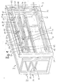
- Fig. 1 eine perspektivische Ansicht einer Vorrichtung für die Zufuhr von Materialstangen, von vorne gesehen;
- Fig. 2 eine schematische Stirnansichtung der Vorrichtung aus Fig. 1; und
- Fig. 3 eine vergrößerte Darstellung eines Details aus der Vorrichtung nach Fig. l und 2.
- Figure 1 is a perspective view of a device for feeding bars of material, seen from the front.
- FIG. 2 shows a schematic end view of the device from FIG. 1; and
- 3 shows an enlarged illustration of a detail from the device according to FIGS. 1 and 2.
Die Vorrichtung für die Zufuhr von Materialstangen besteht im wesentlichen aus zwei Baugruppen, nämlich einem Stangenmagazin 2 und einem vor einer Längsseite des Stangenmagazins 2 aufgestellten Aufzug 3. Die nicht dargestellte Nachschubeinrichtung für eine ebenfalls nicht dargestellte Werkzeugmaschine, beispielsweise einen Drehautomaten, erstreckt sich über dem Stangenmagazin 2 in dessen Längsrichtung. Die Gebrauchsmusterschrift 82 25 574 zeigt beispielsweise einen dem Aufzug 3 ähnlichen Aufzug 30 in seiner räumlichen Zuordnung zu einer Nachschubeinrichtung. Alternativ kommt auch eine andere Art des Anbaus der Vorrichtung an die Nachschubeinrichtung in Frage, wie sie etwa in der Patentschrift 23 50 105 dargestellt ist.The device for feeding material bars essentially consists of two assemblies, namely a
Das Stangenmagazin 2 besteht aus einem rechteckigen Rahmenwerk 20, in welchem mehrere Ebenen 22, 24 übereinander befestigt sind. Jede Ebene weist mehrere beabstandete, fluchtende Leisten 25, 26, 27 auf, die auf einem vorderen Querträger 28 und einem hinteren Querträger 29 des Rahmenwerks 20 befestigt sind. Am jeweiligen vorderen Ende jeder der Leisten 25, 26, 27 sitzt ein erhabener Winkel 31, 32. Auf diese Weise können von hinten, d.h. bei Fig. 2 von links, Materialstangen 33 auf die Leisten 25, 26, 27 aufgelegt werden, welche vermöge der Neigung der Leisten 25, 26, 27 nach vorne und unten auf den Leisten 25, 26, 27 nach vorne bis zur Anlage an die Winkel 31, 32 rollen, so daß auf den Ebenen 22, 24 jeweils eine Lage von nebeneinander liegenden Materialstangen 33, 34 zur Entnahme der jeweils vordersten, an den Winkeln 31, 32 anliegenden Materialstange bereitliegen.The
Der Aufzug 3 weist einen rechtwinkligen Rahmen 35 auf, an dessen Seitenwangen 37, 38 je eine vertikale Spindel 39 befestigt ist. Die Spindel 39 ist am unteren Ende über Kegelräder 40 mit einem Elektromotor 36 gekoppelt, der der Drehantrieb-für die Spindel 39 ist. Der Spindel 39 sowie der in Fig. l nicht dargestellten gegenüberliegenden Spindel sitzt ein Querträger 42. derart, daß bei Drehung der Spindeln der Querträger 42 im Rahmen 35 des Aufzugs 3 aufwärts oder abwärts bewegt wird.The
Auf dem Querträger 42 des Aufzugs 3 sitzen über dessen Längsrichtung beabstandet mehrere Mitnehmer 50, 52, 54, die an dem auf.das Stangenmagazin 2 zuweisenden Ende je eine Kehle zur Aufnahme einer Materialstange besitzen. Da der Rahmen 35 des Aufzugs 3 mit Abstand vor der benachbarten Längsseite des Stangenmagazins 2 aufgestellt ist, können beim Auf- und Niederfahren des Querbalkens 42 die Mitnehmer 50, 52, 54 vor den benachbarten Enden der Leisten 25, 26, 27 vorbeifahren.On the
Gemäß Fig. 3 ist der Mitnehmer 50 als Schieber ausgebildet, der in einer auf dem Querträger 42 befestigten Längsführung 56 durch einen auf eine vorgegebene Wegstrecke einstellbaren Antrieb verschiebbar ist. Dazu ist die Oberseite des Mitnehmers 50 hinter der Kehle 58 mit einer Zahnleiste 60 versehen, mit der ein Zahnrad 62 in Eingriff steht. Das Zahnrad 62 sowie die den weiteren Mitnehmern 52, 54 zugeordneten weiteren Zahnräder 63, 64 sitzen drehfest auf einer Welle 66, die auf dem Querträger 42 in Pfosten 67, 68, 69, 70 drehbar gelagert ist und sich in Längsrichtung des Querträgers 42 erstreckt.3, the
Der einstellbare Antrieb für die Zahnräder 62, b3, 64 und die Mitnehmer 50, besteht aus einem am Querbalken 42 befestigten Druckluftzylinder 72 und einem ebenfalls an: Querträger befestigten Anschlag 74. Der Kolben 73 des Druckluftzylinders 72 ist an einem mit der Welle 66 drehfest verbundenen Arm 71 angelenkt, so daß die Bewegung des Kolbens 73 im Druckluftzylinder 72 zuleiner entsprechenden Drehung der Welle 66 resultiert. Der Druckluftzylinder 72 ist mit einer Wegbegrenzung für den Kolben 73 ausgerüstet, so daß die Welle 66 um einen vorgegebenen Winkel vom Druckluftzylinder 72 gedreht wird.The adjustable drive for the
Der Anschlag 74 wirkt mit einem auf der Welle 66 drehfest sitzenden Finger 76 zusammen und ist mit einem nicht dargestellten Mikroschalter ausgerüstet, der bei Anlaufen des Fingers 76 gegen den Anschlag 74 betätigt . wird. Wie dargestellt, ist der Anschlag 74 relativ zur Welle 66 auf der gleichen Seite wie der Druckluftzylinder 72 am Querträger 42 befestigt. Nicht dargestellt sind die Druckluftzuleitungen zum Druckluftzylinder 72 sowie steuerbare Ventile, die die Beaufschlagung des Druckluftzylinders 72 mit Druckluft in der einen oder anderen Richtung ermöglichen. Ferner nicht dargestellt ist die elektrische Steuerung der Vorrichtung, in deren Eingangskreis der erwähnte Mikroschalter im Anschlag 74 liegt. In Fig. 3 ist die Spindel 41 schematisch angedeutet, die bei Fig. l hinter der Seitenwange 38 des Rahmens 35 drehbar befestigt ist und synchron mit der Spindel 39 vom Elektromotor 36 angetrieben werden kann.The
Die beschriebene Vorrichtung arbeitet wie folgt: in die Ebene 24 werden Materialstangen 33 eines für den Drehautomaten erforderlichen Durchmessers eingelegt, und in die Ebene 22 werden Materialstangen beispielsweise anderen Durchmessers eingelegt. Wenn der Nachschubeinrichtung eine neue Materialstange eines Durchmessers zugeführt werden soll, der dem Durchmesser der in der Ebene 24 bevorrateten Materialstange 33 gleicht, wird der Elektromotor 36 in der Weise eingeschaltet, daß der Querträger 42 von dem aus dem Elektromotor 36 und den Spindeln 39, 41 bestehenden Auf7ugsantrieb im Rahmen 35 abwärts gefahren wird. Der Druckluftzylinder 72 ist so beaufschlagt, daß sein Kolben 73 ganz ausgefahren ist und die Mitnehmer 50, 52, 54 demzufolge sich in ihrer ganz zurückgezogenen Position befinden. In einem nicht dargestellten Programmsteuerwerk, das elektronischer Bauart oaer auch ein mechanisches Schaltwerk sein kann, ist die räumliche Lage der Ebenen 22, 24 relativ zum Querträger 42 gespeichert. Zur Entnahme der benötigten Materialstange aus der Ebene 24 wird dem Programmsteuerwerk ein entsprechender Befehl eingegeben, der bewirkt, daß der Querträger 42 mit den zurückgezogenen Mitnehmern 50, 52, 54 bis kurz unterhalb dem vorderen Ende der Ebene 24 herabfährt. An den vorderen Enden der Leisten 25, 26, 27, etwa an den Winkeln 31, 32, kann ein Mikroschalter eingebaut sein, der von der vordersten, in der Ebene 24 bevorrateten Materialstange betätigt wird und dem Programmsteuerwerk das Vorhandensein wenigstens einer Materialstange in der Ebene 24 meldet. Alternativ kann auf dem Querträger 42 ein Fühler angeordnet sein, der das Vorhandensein der vordersten Materialstange in jeder der Ebenen 22, 24 ertastet und ein entsprechendes Signal dem Programmsteuerwerk liefert.The device described works as follows: in the
Wenn das Vorhandensein einer benötigten Materialstange in der Ebene 24 dem Programmsteuerwerk gemeldet worden ist, bewirkt dieses, daß der Druckluftzylinder 72 in der Weise mit Druckluft beaufschlagt wird, daß sein Kolben 73 in den Zylinder 72 einfährt und über die Welle 66 und die Zahnräder 62, 63, 64 die Mitnehmer 50, 52, 54 synchron in Richtung auf die vorderste Materialstange der Ebene 24 vorschiebt. Die Wegstrecke, um die die Mitnehmer 50, 52, 54 vorgeschoben werden, wird durch die Lage des Anschlags 74 bestimmt, der, wie in Fig. 3 angedeutet, ein Druckluftzylinder mit einstellbarem Kolben 77 sein kann. Sobald der Finger 76 auf dem Kolben 77 des Anschlags 74 auftrifft, wird der erwähnte Mikro-. schalter des Anschlags 74 betätigt, der den weiteren Antrieb der Welle 66 durch den Druckluftzylinder 72 stillsetzt. Die Kehlen 58 der Mitnehmer befinden sich jetzt genau unterhalb der vordersten Materialstange der Ebene 24. Das Programmsteuerwerk fährt nach Betätigung des Mikroschalters im Anschlag 74 den Querbalken 42 so weit hoch, daß die vorderste Materialstange der Ebene 24 von dem Mitnehmer 50, 52, 54 unterfaßt und aus der Ebene 24 herausgehoben wird. Das Programmsteuerwerk veranlaßt sodann, daß der Kolben 73 aus dem Druckluftzylinder 72 wieder ausgefahren wird, bis die Mitnehmer 50, 52, 54 sich wieder in ihrer zurückgezogenen Stellung befinden, wobei jetzt die benötigte Materialstange auf den Mitnehmern 50, 52, 54, und zwar in deren Kehlen 58, ruht. Die mitgenommene Materialstange fährt am vorderen Ende der über der Ebene 24 befindlichen Ebene 22 vorbei nach oben bis zu einer oberen Endstellung, wo sie etwa in der in der erwähnten Gebrauchsmusterschrift dargestellten Weise dem Einlauf der Nachschubeinrichtung übergeben wird.If the presence of a required material bar in
Es versteht sich, daß die Mitnehmer 50, 52, 54 derart in Längsrichtung des Querträgers 42 beabstandet sind, daß sie in den Zwischenraum zwischen den Leisten 25, 26, 27 eingreifen können.It is understood that the
Claims (9)
Applications Claiming Priority (2)
| Application Number | Priority Date | Filing Date | Title |
|---|---|---|---|
| DE19833321164 DE3321164A1 (en) | 1983-06-11 | 1983-06-11 | DEVICE FOR THE FEED OF MATERIAL RODS INTO A SUPPLY DEVICE FOR MACHINE TOOLS, ESPECIALLY TURNING MACHINES |
| DE3321164 | 1983-06-11 |
Publications (2)
| Publication Number | Publication Date |
|---|---|
| EP0129180A1 true EP0129180A1 (en) | 1984-12-27 |
| EP0129180B1 EP0129180B1 (en) | 1986-10-01 |
Family
ID=6201257
Family Applications (1)
| Application Number | Title | Priority Date | Filing Date |
|---|---|---|---|
| EP84106641A Expired EP0129180B1 (en) | 1983-06-11 | 1984-06-09 | Device for the supply of rods of material to a feeding device for machine tools, especially automatic lathes |
Country Status (2)
| Country | Link |
|---|---|
| EP (1) | EP0129180B1 (en) |
| DE (2) | DE3321164A1 (en) |
Cited By (6)
| Publication number | Priority date | Publication date | Assignee | Title |
|---|---|---|---|---|
| DE3707655C1 (en) * | 1987-03-10 | 1988-01-14 | Heinz Dipl-Ing Dornieden | Long material storage facility |
| US5865596A (en) * | 1995-11-16 | 1999-02-02 | Sten Wallsten Nikom Ab | Separating and picking out device |
| CN109262198A (en) * | 2018-09-08 | 2019-01-25 | 芜湖全程智能科技有限公司 | A kind of blanking equipment and its application method for axial workpiece blanking |
| CN112623696A (en) * | 2020-10-30 | 2021-04-09 | 无锡航海精密钢管有限责任公司 | Discharge apparatus is stabilized to tubular product |
| CN113086658A (en) * | 2021-04-19 | 2021-07-09 | 湖北宏博汽车工业智能装备有限公司 | Shaft bin type full-automatic feeding machine |
| CN114030849A (en) * | 2021-11-19 | 2022-02-11 | 中国联合工程有限公司 | Workpiece feeding device of steel pipe inner and outer wall coating production line |
Families Citing this family (3)
| Publication number | Priority date | Publication date | Assignee | Title |
|---|---|---|---|---|
| AT405258B (en) * | 1994-01-27 | 1999-06-25 | Braeuer Franz | DEVICE FOR CUTTING BARS AND FEEDING THE CUTTING BAR PIECES TO A MACHINE TOOL |
| CN111573093B (en) * | 2020-04-10 | 2021-08-20 | 涡阳县康仕达机电有限公司 | Axle finished product transfer device |
| CN112475987B (en) * | 2020-11-06 | 2023-01-06 | 窑街煤电集团甘肃金凯机械制造有限责任公司 | Automatic rod body feeding device for anchor rod processing production line |
Citations (4)
| Publication number | Priority date | Publication date | Assignee | Title |
|---|---|---|---|---|
| US3750804A (en) * | 1969-03-07 | 1973-08-07 | Triax Co | Load handling mechanism and automatic storage system |
| DE2407756A1 (en) * | 1974-02-18 | 1975-08-28 | Norbert Karl Acker | Shelf unloading system - has vehicle with lifting mechanism guided by data carriers to suit item size |
| US4016987A (en) * | 1974-05-31 | 1977-04-12 | Stopa Stahlbau Gmbh & Co. | Storage system |
| DE2350105C2 (en) * | 1972-10-07 | 1983-03-17 | I.E.M.C.A. S.p.A. Industria Elettromeccanica Complessi Automatici, Faenza, Ravenna | Device for feeding bars of material into a feeding device for machine tools |
-
1983
- 1983-06-11 DE DE19833321164 patent/DE3321164A1/en not_active Withdrawn
-
1984
- 1984-06-09 DE DE8484106641T patent/DE3460862D1/en not_active Expired
- 1984-06-09 EP EP84106641A patent/EP0129180B1/en not_active Expired
Patent Citations (4)
| Publication number | Priority date | Publication date | Assignee | Title |
|---|---|---|---|---|
| US3750804A (en) * | 1969-03-07 | 1973-08-07 | Triax Co | Load handling mechanism and automatic storage system |
| DE2350105C2 (en) * | 1972-10-07 | 1983-03-17 | I.E.M.C.A. S.p.A. Industria Elettromeccanica Complessi Automatici, Faenza, Ravenna | Device for feeding bars of material into a feeding device for machine tools |
| DE2407756A1 (en) * | 1974-02-18 | 1975-08-28 | Norbert Karl Acker | Shelf unloading system - has vehicle with lifting mechanism guided by data carriers to suit item size |
| US4016987A (en) * | 1974-05-31 | 1977-04-12 | Stopa Stahlbau Gmbh & Co. | Storage system |
Cited By (8)
| Publication number | Priority date | Publication date | Assignee | Title |
|---|---|---|---|---|
| DE3707655C1 (en) * | 1987-03-10 | 1988-01-14 | Heinz Dipl-Ing Dornieden | Long material storage facility |
| EP0281955A2 (en) | 1987-03-10 | 1988-09-14 | Heinz Dornieden | Storage device for long articles |
| US5865596A (en) * | 1995-11-16 | 1999-02-02 | Sten Wallsten Nikom Ab | Separating and picking out device |
| CN109262198A (en) * | 2018-09-08 | 2019-01-25 | 芜湖全程智能科技有限公司 | A kind of blanking equipment and its application method for axial workpiece blanking |
| CN112623696A (en) * | 2020-10-30 | 2021-04-09 | 无锡航海精密钢管有限责任公司 | Discharge apparatus is stabilized to tubular product |
| CN113086658A (en) * | 2021-04-19 | 2021-07-09 | 湖北宏博汽车工业智能装备有限公司 | Shaft bin type full-automatic feeding machine |
| CN113086658B (en) * | 2021-04-19 | 2022-09-27 | 湖北宏博汽车工业智能装备有限公司 | Shaft bin type full-automatic feeding machine |
| CN114030849A (en) * | 2021-11-19 | 2022-02-11 | 中国联合工程有限公司 | Workpiece feeding device of steel pipe inner and outer wall coating production line |
Also Published As
| Publication number | Publication date |
|---|---|
| DE3321164A1 (en) | 1984-12-13 |
| EP0129180B1 (en) | 1986-10-01 |
| DE3460862D1 (en) | 1986-11-06 |
Similar Documents
| Publication | Publication Date | Title |
|---|---|---|
| DE3346523C2 (en) | Device for assembling a motor vehicle body | |
| DE3006229C2 (en) | System for sorting and filing stacks of sheets | |
| DE3422661A1 (en) | Apparatus for feeding cut-to-length longitudinal wires to a grid welding machine | |
| EP0129180B1 (en) | Device for the supply of rods of material to a feeding device for machine tools, especially automatic lathes | |
| DE1095297B (en) | Sheet feeder with several pile hoists | |
| EP0150809B1 (en) | Apparatus for removing and stacking cuttings of sheet metal falling behind the cutting line of a plate-shearing machine | |
| DE1813048B2 (en) | DEVICE FOR SEPARATING WASTE PARTS ON CONTAINERS MADE OF THERMOPLASTIC PLASTIC | |
| DE1939395B2 (en) | Magazine filling device for cigarette processing machines | |
| DE1552422A1 (en) | Bar loading magazine | |
| DE1228275B (en) | Machine for the orderly stacking of flat objects, for example newspapers | |
| DE3010517C2 (en) | Folding machine with a paper feeder | |
| AT362404B (en) | FEEDING DEVICE FOR SHEETS OD. DGL. | |
| DE8317102U1 (en) | Device for feeding bars of material into a feeding device for machine tools, in particular automatic lathes | |
| CH432366A (en) | Storage arrangement | |
| DE1950292A1 (en) | Sawing machine | |
| DE2724284A1 (en) | Loading equipment for letters - has control operating circulating drive according to signal from sensor in stacking mechanism region | |
| DE19819596C2 (en) | Sheet retainer for a non-stop stack changer | |
| DE3434446C2 (en) | ||
| DE1602460B2 (en) | LIFTING DEVICE FOR A PRESS BRAKE | |
| DE19507740A1 (en) | Stacker for folded drawings | |
| DE2408536C2 (en) | Device for the controlled loading of filling, processing and other machines with cup-shaped containers to be filled or processed | |
| DE1536429C (en) | Device for different types and colors of printing empty bags made of e.g. plastic film or paper | |
| DE2119372C3 (en) | Device for the automatic folding of sheet material | |
| DE947153C (en) | Loading device of a machine tool provided with a material container | |
| DE2910091A1 (en) | DEVICE FOR THE TRANSFER OF A COIL BODY |
Legal Events
| Date | Code | Title | Description |
|---|---|---|---|
| PUAI | Public reference made under article 153(3) epc to a published international application that has entered the european phase |
Free format text: ORIGINAL CODE: 0009012 |
|
| AK | Designated contracting states |
Designated state(s): CH DE FR GB IT LI |
|
| 17P | Request for examination filed |
Effective date: 19841120 |
|
| ITF | It: translation for a ep patent filed |
Owner name: UFFICIO TECNICO ING. A. MANNUCCI |
|
| RAP1 | Party data changed (applicant data changed or rights of an application transferred) |
Owner name: FECHENBACH-COLLENBERGER MASCHINENBAU GMBH |
|
| GRAA | (expected) grant |
Free format text: ORIGINAL CODE: 0009210 |
|
| AK | Designated contracting states |
Kind code of ref document: B1 Designated state(s): CH DE FR GB IT LI |
|
| REF | Corresponds to: |
Ref document number: 3460862 Country of ref document: DE Date of ref document: 19861106 |
|
| ET | Fr: translation filed | ||
| RAP2 | Party data changed (patent owner data changed or rights of a patent transferred) |
Owner name: FMB MASCHINENBAU GMBH |
|
| PLBE | No opposition filed within time limit |
Free format text: ORIGINAL CODE: 0009261 |
|
| STAA | Information on the status of an ep patent application or granted ep patent |
Free format text: STATUS: NO OPPOSITION FILED WITHIN TIME LIMIT |
|
| 26N | No opposition filed | ||
| ITTA | It: last paid annual fee | ||
| REG | Reference to a national code |
Ref country code: CH Ref legal event code: PUE Owner name: FMB MASCHINENBAU GMBH TRANSFER- FMB MASCHINENBAUGE |
|
| REG | Reference to a national code |
Ref country code: GB Ref legal event code: 732E |
|
| PGFP | Annual fee paid to national office [announced via postgrant information from national office to epo] |
Ref country code: GB Payment date: 20010521 Year of fee payment: 18 |
|
| PGFP | Annual fee paid to national office [announced via postgrant information from national office to epo] |
Ref country code: DE Payment date: 20010531 Year of fee payment: 18 |
|
| PGFP | Annual fee paid to national office [announced via postgrant information from national office to epo] |
Ref country code: FR Payment date: 20010618 Year of fee payment: 18 |
|
| PGFP | Annual fee paid to national office [announced via postgrant information from national office to epo] |
Ref country code: CH Payment date: 20010622 Year of fee payment: 18 |
|
| REG | Reference to a national code |
Ref country code: GB Ref legal event code: IF02 |
|
| PG25 | Lapsed in a contracting state [announced via postgrant information from national office to epo] |
Ref country code: GB Free format text: LAPSE BECAUSE OF NON-PAYMENT OF DUE FEES Effective date: 20020609 |
|
| PG25 | Lapsed in a contracting state [announced via postgrant information from national office to epo] |
Ref country code: LI Free format text: LAPSE BECAUSE OF NON-PAYMENT OF DUE FEES Effective date: 20020630 Ref country code: CH Free format text: LAPSE BECAUSE OF NON-PAYMENT OF DUE FEES Effective date: 20020630 |
|
| PG25 | Lapsed in a contracting state [announced via postgrant information from national office to epo] |
Ref country code: DE Free format text: LAPSE BECAUSE OF NON-PAYMENT OF DUE FEES Effective date: 20030101 |
|
| GBPC | Gb: european patent ceased through non-payment of renewal fee |
Effective date: 20020609 |
|
| REG | Reference to a national code |
Ref country code: CH Ref legal event code: PL |
|
| PG25 | Lapsed in a contracting state [announced via postgrant information from national office to epo] |
Ref country code: FR Free format text: LAPSE BECAUSE OF NON-PAYMENT OF DUE FEES Effective date: 20030228 |
|
| REG | Reference to a national code |
Ref country code: FR Ref legal event code: ST |