EP0127397A1 - A construction element - Google Patents
A construction element Download PDFInfo
- Publication number
- EP0127397A1 EP0127397A1 EP84303357A EP84303357A EP0127397A1 EP 0127397 A1 EP0127397 A1 EP 0127397A1 EP 84303357 A EP84303357 A EP 84303357A EP 84303357 A EP84303357 A EP 84303357A EP 0127397 A1 EP0127397 A1 EP 0127397A1
- Authority
- EP
- European Patent Office
- Prior art keywords
- jaws
- construction element
- jaw
- element according
- free ends
- Prior art date
- Legal status (The legal status is an assumption and is not a legal conclusion. Google has not performed a legal analysis and makes no representation as to the accuracy of the status listed.)
- Granted
Links
Images


Classifications
-
- A—HUMAN NECESSITIES
- A63—SPORTS; GAMES; AMUSEMENTS
- A63H—TOYS, e.g. TOPS, DOLLS, HOOPS OR BUILDING BLOCKS
- A63H33/00—Other toys
- A63H33/04—Building blocks, strips, or similar building parts
- A63H33/06—Building blocks, strips, or similar building parts to be assembled without the use of additional elements
- A63H33/065—Building blocks, strips, or similar building parts to be assembled without the use of additional elements using elastic deformation
-
- Y—GENERAL TAGGING OF NEW TECHNOLOGICAL DEVELOPMENTS; GENERAL TAGGING OF CROSS-SECTIONAL TECHNOLOGIES SPANNING OVER SEVERAL SECTIONS OF THE IPC; TECHNICAL SUBJECTS COVERED BY FORMER USPC CROSS-REFERENCE ART COLLECTIONS [XRACs] AND DIGESTS
- Y10—TECHNICAL SUBJECTS COVERED BY FORMER USPC
- Y10T—TECHNICAL SUBJECTS COVERED BY FORMER US CLASSIFICATION
- Y10T403/00—Joints and connections
- Y10T403/70—Interfitted members
- Y10T403/7016—Diametric end slot is joint component
-
- Y—GENERAL TAGGING OF NEW TECHNOLOGICAL DEVELOPMENTS; GENERAL TAGGING OF CROSS-SECTIONAL TECHNOLOGIES SPANNING OVER SEVERAL SECTIONS OF THE IPC; TECHNICAL SUBJECTS COVERED BY FORMER USPC CROSS-REFERENCE ART COLLECTIONS [XRACs] AND DIGESTS
- Y10—TECHNICAL SUBJECTS COVERED BY FORMER USPC
- Y10T—TECHNICAL SUBJECTS COVERED BY FORMER US CLASSIFICATION
- Y10T403/00—Joints and connections
- Y10T403/70—Interfitted members
- Y10T403/7045—Interdigitated ends
Definitions
- the invention relates to a construction element of the type which can be used, for example, with further construction elements to build models, shapes or patterns.
- US Patent No. 3 550 311 describes elongate construction elements having interengageable jaws, which enable the elements to be joined end to end coaxially.
- the jaws lie in the same plane when joined together and rely solely on friction to prevent the jaws sliding sideways relative to each other and becoming detached.
- the jaws are of complex form and tend to project considerably beyond the cylindrical surface of a rod on which they are snap fitted.
- US No. 2959888 describes interlockable toy elements which also have jaws which snap together.
- the jaws of the elements in this case lie in mutually transverse planes and, therefore, are mechanically resistant to separation by relative sideways movement.
- the frictional fit of the jaws will permit relative pivoting of the elements in the transverse planes. This can be a disadvantage when making, say, supporting legs of a model where a considerable amount of rigidity is required.
- An object of the present invention is to provide a construction element having a jaw which can be located in a similar jaw of a further construction element in a manner which will provide a substantially rigid interconnection mechanically resistant to separation by sideways applied forces.
- a construction element comprising a body having resiliently openable jaws thereon locatable between similar jaws of a further construction element with the jaws of the respective elements arranged in mutually transverse planes, and a jaw retention surface on the body, said jaws defining an open front end between free ends thereof whereby said jaws locate each other with the free ends of the jaws of each element cooperating with said retention surface on the other element to inhibit relative movement between the elements.
- the arrangement of the located jaws in mutually transverse planes provides the required mechanical resistance to sideways applied separation forces and the jaw retention means on the body provides the desired rigid interconnection of the two elements which gives, e.g. useful resistance to relative angular deflection of interconnected elements.
- the jaws have a closed rear end so that when the jaws are located in the similar jaws the free ends of the jaws of each element are positioned behind the closed rear end of the other jaws for engagement with the retention surface.
- the retention surface may be defined by a rear surface of means defining the said closed rear end of the jaws.
- the retention surface may comprise a groove in the body behind a closed rear end of the jaws so that when the jaws are located between the similar jaws the free ends of the jaws of each element locate in the groove behind the closed rear end of the other jaws.
- the aforesaid rear surface of the means defining the closed rear end of the jaws may form a wall of said groove. The use of the groove provides a very positive location for the free ends of the jaws when the two sets of jaws are brought together.
- the free ends of the jaws of each element engage the retention surface of the other element in a snap-fit manner.
- the snap-fit provides optimum resistance to direct separation of the sets of jaws as well as increased resistance to separation by relative angular movement of the interconnected elements.
- the body is preferably elongate and may have the jaws at an end thereof.
- the jaws are preferably dimensioned so as to snap-fit on to the body of a similar construction element.
- the elongate body could, of course, have jaws at each end which would preferably lie in a common plane.
- the elongate body may have jaws at one end and a jaw locating member at its other end extending transversely of the body.
- the jaw locating member is arranged so that when the jaws of said similar construction element are located on the member they lie in a plane transverse to the plane containing the jaws at said one end of the body.
- the jaw locating member may comprise a transverse bar mounted on a support such as finger means on the body.
- the finger means may comprise two spaced fingers on the body interconnected at or adjacent free ends by the bar.
- Means may be provided for inhibiting rotational movement of jaws located on the jaw locating member.
- Such means may comprise a projection, e.g. a rib or flange, on said member which lies between said free ends of the jaws when the jaws are located on the member.
- a construction element 10 is moulded from resilient plastics and comprises an elongate body 1 of circular cross section.
- Two jaws 2 are formed at each end of the body and have free ends 3.
- Each pair of jaws 2 has an open front end 4 defined between the free ends 3 and a closed rear end 5 defined by an end section 6.
- Circumferential grooves 7 are formed in the body 1 immediately behind the end sections 6, a wall of each groove forming a rear surface 8 of the adjacent end section.
- the jaws 2 can be located on the body 1 of another element 9, the distance X (Fig.3) between the free ends 3 being less than the diameter D (Fig.4) of the body.
- Such location is effected by first placing the body 1 of the other element 9 against the free ends 3 of the jaws 2.
- a force in direction F is then applied to the element 9 thereby causing the resilient jaws to open and receive the body 1.
- the jaws 2 snap-fit on to the body 1 whereby the flat internal surfaces of the jaws 2 and end section 6 grip the body 1 at points around its periphery whilst permitting relative rotation between the two elements 9, 10 about the axis of element 9.
- Fig.6 shows the way in which jaws of the construction element 9 can be located between the jaws of construction element 10.
- the elements are first rotated about their longitudinal axes until the jaws lie in mutually perpendicular planes.
- the jaws 2 of element 9 lie in a vertical plane and the jaws 2 of element 10 lie in a horizontal plane.
- the open ends 4 of the jaws are then moved towards each other until the free ends 3 interengage.
- the distance X is less than the width of the jaws and so axial loading is necessary to cause the free ends 3 to ride over each other to permit initial intercalating of the jaws. Further axial loading is then applied to cause the free ends of the jaws of each element to ride over the end section 6 associated with the jaws of the other element and to snap into the grooves 7.
- Each of the free ends 3 thereby resiliently engages along a straight line 8a defined by part of the end section 6 adjacent surface 8 of the relevant end section 6 and also engages a point P on an opposite edge of the relevant groove 7.
- the joint achieved by the intercalating jaws provides high resistance to separation by sideways applied forces S in vertical, horizontal or intermediate planes.
- the joint is capable of transmitting compressive forces, rotational forces R from one element to the other and is resistant to tensile separation or separation by relative angular displacement of the elements in any plane.
- the strength of the joint is greatly enhanced by the substantial line contact between the free ends 3 and end section 6 coupled with the spaced point contact P.
- line contact along 8a is preferred, it will be appreciated that contact of a jaw with spaced points lying, say, adjacent opposite ends of line 8 and with point P will provide a strong joint.
- the jaws grip the body I as in Fig. 5, the body 1 may be of reduced diameter to avoid the need ; for a groove 7. The jaws would then be retained simply by the surfaces 8.
- Fig.7 illustrates a way of overcoming that.
- one end of an element 11 carries jaws 2 whilst the opposite end has two parallel fingers 12 interconnected by a cylindrical bar 13 having a diameter equal to D. Jaws of a further element can be snapped on to the bar 13.
- the axis of the bar 13 lies in the same plane as the jaws 2 at the other end of the element or in a plane substantially parallel therewith.
- the elment 11 is used, say, in place of element 10 in Fig.6, jaws of a further element which locate on bar 13 will lie in the same plane as the jaws of element 9. If it is desired to prevent or limit rotation of jaws around the bar 13, the bar can be formed with a rib or flange 14 as shown in Fig.8. The flange lies between the free ends 3 of the jaws 2.
- Fig.9 shows an alternative means of preventing or limiting rotation about bar 13 by using a tapering web 14'which extends between the bar 13 and the adjacent end of the body.
- the body 1 has its end opposite the jaws 2 formed with a transverse bar 20, a groove 7 being formed in the body adjacent the bar.
- Jaws 2 of a further element can be located in position a, b ore as indicated in broken lines in Fig. 10. In positions a and c the jaws 2 can rotate about the bar 20 but in position b the jaws engage the groove 7 and such rotation is therefore prevented.
- a rotary interconnection between the jaws 2 and the bars 13, 20 enable a knuckle type joint to be formed between two elements.
- Construction elements in accordance with the invention can be used to form an infinite variety of patterns, geometric designs, models etc. and may be supplied in a pack containing elements in various colours and other constructional components such as wheels or rings.
Landscapes
- Joining Of Building Structures In Genera (AREA)
Abstract
Description
- The invention relates to a construction element of the type which can be used, for example, with further construction elements to build models, shapes or patterns.
- Many types of constructional elements have been proposed over the years. For example US Patent No. 3 550 311 describes elongate construction elements having interengageable jaws, which enable the elements to be joined end to end coaxially. However the jaws lie in the same plane when joined together and rely solely on friction to prevent the jaws sliding sideways relative to each other and becoming detached. Moreover the jaws are of complex form and tend to project considerably beyond the cylindrical surface of a rod on which they are snap fitted. US No. 2959888 describes interlockable toy elements which also have jaws which snap together. The jaws of the elements in this case lie in mutually transverse planes and, therefore, are mechanically resistant to separation by relative sideways movement. However the frictional fit of the jaws will permit relative pivoting of the elements in the transverse planes. This can be a disadvantage when making, say, supporting legs of a model where a considerable amount of rigidity is required.
- An object of the present invention is to provide a construction element having a jaw which can be located in a similar jaw of a further construction element in a manner which will provide a substantially rigid interconnection mechanically resistant to separation by sideways applied forces.
- According to the invention there is provided a construction element comprising a body having resiliently openable jaws thereon locatable between similar jaws of a further construction element with the jaws of the respective elements arranged in mutually transverse planes, and a jaw retention surface on the body, said jaws defining an open front end between free ends thereof whereby said jaws locate each other with the free ends of the jaws of each element cooperating with said retention surface on the other element to inhibit relative movement between the elements.
- The arrangement of the located jaws in mutually transverse planes provides the required mechanical resistance to sideways applied separation forces and the jaw retention means on the body provides the desired rigid interconnection of the two elements which gives, e.g. useful resistance to relative angular deflection of interconnected elements.
- Preferably the jaws have a closed rear end so that when the jaws are located in the similar jaws the free ends of the jaws of each element are positioned behind the closed rear end of the other jaws for engagement with the retention surface. This arrangement results in a particularly rigid joint between elements. In such a case the retention surface may be defined by a rear surface of means defining the said closed rear end of the jaws.
- The retention surface may comprise a groove in the body behind a closed rear end of the jaws so that when the jaws are located between the similar jaws the free ends of the jaws of each element locate in the groove behind the closed rear end of the other jaws. The aforesaid rear surface of the means defining the closed rear end of the jaws may form a wall of said groove. The use of the groove provides a very positive location for the free ends of the jaws when the two sets of jaws are brought together.
- Preferably the free ends of the jaws of each element engage the retention surface of the other element in a snap-fit manner. The snap-fit provides optimum resistance to direct separation of the sets of jaws as well as increased resistance to separation by relative angular movement of the interconnected elements.
- The body is preferably elongate and may have the jaws at an end thereof. The jaws are preferably dimensioned so as to snap-fit on to the body of a similar construction element. The elongate body could, of course, have jaws at each end which would preferably lie in a common plane.
- The elongate body may have jaws at one end and a jaw locating member at its other end extending transversely of the body. Preferably the jaw locating member is arranged so that when the jaws of said similar construction element are located on the member they lie in a plane transverse to the plane containing the jaws at said one end of the body. The jaw locating member may comprise a transverse bar mounted on a support such as finger means on the body. The finger means may comprise two spaced fingers on the body interconnected at or adjacent free ends by the bar. Means may be provided for inhibiting rotational movement of jaws located on the jaw locating member. Such means may comprise a projection, e.g. a rib or flange, on said member which lies between said free ends of the jaws when the jaws are located on the member.
- A construction element in accordance with the invention will now be described by way of example with reference to the accompanying drawings in which:-
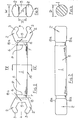
- Fig. 1 is an elevation of one form of construction element in accordance with the invention having jaws at each end,
- Fig.2 is a plan view of the element shown in Fig.1,
- Fig.3 is an end view of the element of Fig.1,
- Fig.4 is a cross-section of the element of Fig.1 on the line IV-IV in Fig.1,
- Fig.5 shows the way in which jaws of the element grip the body of another element,
- Fig.6 shows the way in which two sets of jaws are located one within the other,
- Fig.7 shows an alternative form of element having a jaw locating member at one end and jaws at the other end,
- Fig.6 is a cross section through the jaw locating member in Fig.7 on the line VIII-VIII in Fig.7,
- Fig.9 is a cross section through an alternative form of jaw locating member, and
- Figs. 10 and 11 are elevation and plan views respectively of an element having another form of jaw locating member.
- Referring to Figs. 1 to 4 a
construction element 10 is moulded from resilient plastics and comprises anelongate body 1 of circular cross section. Twojaws 2 are formed at each end of the body and havefree ends 3. Each pair ofjaws 2 has anopen front end 4 defined between thefree ends 3 and a closedrear end 5 defined by anend section 6.Circumferential grooves 7 are formed in thebody 1 immediately behind theend sections 6, a wall of each groove forming arear surface 8 of the adjacent end section. - As shown in Fig.5, the
jaws 2 can be located on thebody 1 of anotherelement 9, the distance X (Fig.3) between thefree ends 3 being less than the diameter D (Fig.4) of the body. Such location is effected by first placing thebody 1 of theother element 9 against thefree ends 3 of thejaws 2. A force in direction F is then applied to theelement 9 thereby causing the resilient jaws to open and receive thebody 1. In view of the resilience of the plastics material, thejaws 2 snap-fit on to thebody 1 whereby the flat internal surfaces of thejaws 2 andend section 6 grip thebody 1 at points around its periphery whilst permitting relative rotation between the twoelements element 9. - Fig.6 shows the way in which jaws of the
construction element 9 can be located between the jaws ofconstruction element 10. To locate the jaws, the elements are first rotated about their longitudinal axes until the jaws lie in mutually perpendicular planes. In Figo6, thejaws 2 ofelement 9 lie in a vertical plane and thejaws 2 ofelement 10 lie in a horizontal plane. Theopen ends 4 of the jaws are then moved towards each other until thefree ends 3 interengage. - The distance X is less than the width of the jaws and so axial loading is necessary to cause the
free ends 3 to ride over each other to permit initial intercalating of the jaws. Further axial loading is then applied to cause the free ends of the jaws of each element to ride over theend section 6 associated with the jaws of the other element and to snap into thegrooves 7. Each of thefree ends 3 thereby resiliently engages along astraight line 8a defined by part of theend section 6adjacent surface 8 of therelevant end section 6 and also engages a point P on an opposite edge of therelevant groove 7. As thejaws 2 of one element overlap thejaws 2 of the other element in a snap-fit manner, the joint achieved by the intercalating jaws provides high resistance to separation by sideways applied forces S in vertical, horizontal or intermediate planes. Also, the joint is capable of transmitting compressive forces, rotational forces R from one element to the other and is resistant to tensile separation or separation by relative angular displacement of the elements in any plane. The strength of the joint is greatly enhanced by the substantial line contact between thefree ends 3 andend section 6 coupled with the spaced point contact P. Although line contact along 8a is preferred, it will be appreciated that contact of a jaw with spaced points lying, say, adjacent opposite ends ofline 8 and with point P will provide a strong joint. - Where it is not essential that. the jaws grip the body I as in Fig. 5, the
body 1 may be of reduced diameter to avoid the need ; for agroove 7. The jaws would then be retained simply by thesurfaces 8. - Where the elements are connected as shown in Fig. 6, the jaws at the opposite end of
element 9 will be in a plane perpendicular to the plane containing the jaws at the opposite end ofelement 10. This may be inconvenient in some instances and Fig.7 illustrates a way of overcoming that. In Fig.7 one end of an element 11 carriesjaws 2 whilst the opposite end has twoparallel fingers 12 interconnected by acylindrical bar 13 having a diameter equal to D. Jaws of a further element can be snapped on to thebar 13. The axis of thebar 13 lies in the same plane as thejaws 2 at the other end of the element or in a plane substantially parallel therewith. Therefore if the elment 11 is used, say, in place ofelement 10 in Fig.6, jaws of a further element which locate onbar 13 will lie in the same plane as the jaws ofelement 9. If it is desired to prevent or limit rotation of jaws around thebar 13, the bar can be formed with a rib orflange 14 as shown in Fig.8. The flange lies between the free ends 3 of thejaws 2. - Fig.9 shows an alternative means of preventing or limiting rotation about
bar 13 by using a tapering web 14'which extends between thebar 13 and the adjacent end of the body. - In the embodiments of Figs 7,8 and 9 the distance E between the fingers is slightly greater than W.
- In Figs. 10 and 11 the
body 1 has its end opposite thejaws 2 formed with atransverse bar 20, agroove 7 being formed in the body adjacent the bar.Jaws 2 of a further element can be located in position a, b ore as indicated in broken lines in Fig. 10. In positions a and c thejaws 2 can rotate about thebar 20 but in position b the jaws engage thegroove 7 and such rotation is therefore prevented. - A rotary interconnection between the
jaws 2 and thebars - Whilst specific reference has been made to a body which is of elongate form the body could be of a non elongate form.
- Construction elements in accordance with the invention can be used to form an infinite variety of patterns, geometric designs, models etc. and may be supplied in a pack containing elements in various colours and other constructional components such as wheels or rings.
- Whilst specific embodiments of the invention have been shown and described in detail it will be understood that the embodiments may be modified or varied without departing from the spirit or scope of the invention.
Claims (10)
Applications Claiming Priority (2)
| Application Number | Priority Date | Filing Date | Title |
|---|---|---|---|
| GB838313507A GB8313507D0 (en) | 1983-05-17 | 1983-05-17 | Connector |
| GB8313507 | 1983-05-17 |
Publications (2)
| Publication Number | Publication Date |
|---|---|
| EP0127397A1 true EP0127397A1 (en) | 1984-12-05 |
| EP0127397B1 EP0127397B1 (en) | 1988-12-14 |
Family
ID=10542834
Family Applications (1)
| Application Number | Title | Priority Date | Filing Date |
|---|---|---|---|
| EP84303357A Expired EP0127397B1 (en) | 1983-05-17 | 1984-05-17 | A construction element |
Country Status (4)
| Country | Link |
|---|---|
| US (1) | US4548590A (en) |
| EP (1) | EP0127397B1 (en) |
| DE (1) | DE3475594D1 (en) |
| GB (1) | GB8313507D0 (en) |
Cited By (1)
| Publication number | Priority date | Publication date | Assignee | Title |
|---|---|---|---|---|
| US5049104A (en) * | 1989-02-24 | 1991-09-17 | Interlego A.G. | Connecting means for a toy building set |
Families Citing this family (46)
| Publication number | Priority date | Publication date | Assignee | Title |
|---|---|---|---|---|
| IL76426A0 (en) * | 1985-09-19 | 1986-01-31 | Asher Gat | Assembly toys for joining cylindrical objects |
| DE8717713U1 (en) * | 1987-09-17 | 1989-10-12 | Wolf, Elmar, 8706 Hoechberg, De | |
| US4900090A (en) * | 1987-10-08 | 1990-02-13 | Roplas Sales Pty. Ltd. | Slat assembled chair and method of assembly thereof |
| US5056291A (en) * | 1989-10-19 | 1991-10-15 | Skilland Engineering, Ltd. | Modular system for space frame structures |
| DE4105763A1 (en) * | 1991-02-23 | 1992-08-27 | Suspa Compart Ag | LINKING A VIBRATION DAMPER FOR A WASHING MACHINE |
| US5123123A (en) * | 1991-01-17 | 1992-06-23 | American Standard Inc. | Bathtub overflow control device |
| US5305576A (en) * | 1992-05-07 | 1994-04-26 | Giles Brian C | Method of constructing curvilinear structures |
| US5871384A (en) * | 1993-04-20 | 1999-02-16 | Kichijo; Hiroshi | Block assembly and devices formed thereby |
| US5503497A (en) * | 1994-09-19 | 1996-04-02 | Op-D-Op, Inc. | Ratchet link |
| US5582488A (en) * | 1994-09-19 | 1996-12-10 | Op-D-Op, Inc. | Ratchet link |
| IL112421A (en) * | 1995-01-24 | 1997-11-20 | Tiltan Technologiot Tlat Meima | Construction element |
| AU708568B2 (en) * | 1995-12-11 | 1999-08-05 | Zoob Corporation | Construction system |
| US6672931B1 (en) | 2000-11-14 | 2004-01-06 | Jim Bagley | Interconnectable model construction elements |
| US6572429B2 (en) * | 2001-01-02 | 2003-06-03 | Huntar, Inc. | Toy model building set |
| US6948998B2 (en) * | 2003-02-07 | 2005-09-27 | Jim Bagley | Interconnectable model construction elements |
| US7588033B2 (en) | 2003-06-18 | 2009-09-15 | Breathe Technologies, Inc. | Methods, systems and devices for improving ventilation in a lung area |
| JP2007506480A (en) * | 2003-08-18 | 2007-03-22 | ワンドカ,アンソニー・ディ | Methods and apparatus for non-invasive ventilation with a nasal interface |
| JP2008511383A (en) * | 2004-09-02 | 2008-04-17 | スカボロー,デーン | Toy construction set method and apparatus |
| US20090149110A1 (en) * | 2004-09-02 | 2009-06-11 | Dane Scarborough | Toy construction set |
| US7326100B2 (en) * | 2005-02-18 | 2008-02-05 | O'brien Gilford | Marble building toy |
| EP1926517A2 (en) | 2005-09-20 | 2008-06-04 | Lutz Freitag | Systems, methods and apparatus for respiratory support of a patient |
| JP5191005B2 (en) | 2006-05-18 | 2013-04-24 | ブリーズ テクノロジーズ, インコーポレイテッド | Method and device for tracheostomy |
| US8172636B1 (en) | 2006-09-15 | 2012-05-08 | Pull-Buoy, Inc. | Playground hoop-holding apparatus |
| CN101720247A (en) * | 2007-02-09 | 2010-06-02 | 鹰飞能玩具公司 | Construction system |
| WO2008144589A1 (en) | 2007-05-18 | 2008-11-27 | Breathe Technologies, Inc. | Methods and devices for sensing respiration and providing ventilation therapy |
| US8567399B2 (en) | 2007-09-26 | 2013-10-29 | Breathe Technologies, Inc. | Methods and devices for providing inspiratory and expiratory flow relief during ventilation therapy |
| JP5513392B2 (en) | 2007-09-26 | 2014-06-04 | ブリーズ・テクノロジーズ・インコーポレーテッド | Method and apparatus for treating sleep apnea |
| US20090108550A1 (en) * | 2007-10-29 | 2009-04-30 | Samsung Gwangju Electronics Co., Ltd. | Wheel connection apparatus and cleaner having the same |
| EP2082791B1 (en) | 2008-01-25 | 2010-05-19 | Saso Stevkovski | Construction system and applications thereof |
| JP5758799B2 (en) | 2008-04-18 | 2015-08-05 | ブリーズ・テクノロジーズ・インコーポレーテッド | Method and device for sensing respiratory effects and controlling ventilator function |
| US8770193B2 (en) | 2008-04-18 | 2014-07-08 | Breathe Technologies, Inc. | Methods and devices for sensing respiration and controlling ventilator functions |
| CA2734296C (en) | 2008-08-22 | 2018-12-18 | Breathe Technologies, Inc. | Methods and devices for providing mechanical ventilation with an open airway interface |
| CA2739435A1 (en) | 2008-10-01 | 2010-04-08 | Breathe Technologies, Inc. | Ventilator with biofeedback monitoring and control for improving patient activity and health |
| US9132250B2 (en) | 2009-09-03 | 2015-09-15 | Breathe Technologies, Inc. | Methods, systems and devices for non-invasive ventilation including a non-sealing ventilation interface with an entrainment port and/or pressure feature |
| WO2010115170A2 (en) | 2009-04-02 | 2010-10-07 | Breathe Technologies, Inc. | Methods, systems and devices for non-invasive open ventilation for treating airway obstructions |
| US9962512B2 (en) | 2009-04-02 | 2018-05-08 | Breathe Technologies, Inc. | Methods, systems and devices for non-invasive ventilation including a non-sealing ventilation interface with a free space nozzle feature |
| CA2774902C (en) | 2009-09-03 | 2017-01-03 | Breathe Technologies, Inc. | Methods, systems and devices for non-invasive ventilation including a non-sealing ventilation interface with an entrainment port and/or pressure feature |
| JP5891226B2 (en) | 2010-08-16 | 2016-03-22 | ブリーズ・テクノロジーズ・インコーポレーテッド | Method, system and apparatus for providing ventilatory assistance using LOX |
| WO2012045051A1 (en) | 2010-09-30 | 2012-04-05 | Breathe Technologies, Inc. | Methods, systems and devices for humidifying a respiratory tract |
| BE1019854A3 (en) * | 2011-02-28 | 2013-01-08 | Vandoren Rolf | CONSTRUCTION TOYS. |
| ITAN20130234A1 (en) * | 2013-12-05 | 2014-03-06 | Riplast S R L | SYSTEM OF MOUNTING ELEMENTS FOR TOY CONSTRUCTION. |
| USD783729S1 (en) * | 2014-07-25 | 2017-04-11 | GoldieBlox, Inc. | Angle compatible block |
| US9573075B1 (en) * | 2016-05-17 | 2017-02-21 | Kids Toy Clab, LLC. | Illuminated toy construction apparatus |
| US10792449B2 (en) | 2017-10-03 | 2020-10-06 | Breathe Technologies, Inc. | Patient interface with integrated jet pump |
| USD936752S1 (en) * | 2020-01-22 | 2021-11-23 | Costas Sisamos | Snap-lock construction toy axle |
| USD931947S1 (en) * | 2020-09-18 | 2021-09-28 | Jierong Wang | Connector piece for toy building set |
Citations (4)
| Publication number | Priority date | Publication date | Assignee | Title |
|---|---|---|---|---|
| US2959888A (en) * | 1959-09-15 | 1960-11-15 | Ideal Toy Corp | Interlockable toy elements |
| DK90840C (en) * | 1955-09-14 | 1961-05-01 | Holger Louis Hansen | Building elements. |
| US3392480A (en) * | 1965-06-10 | 1968-07-16 | Kohner Bros Inc | Child's construction game |
| US3550311A (en) * | 1967-09-20 | 1970-12-29 | John J Fouquart | Interengageable construction elements with resilient clutching parts |
Family Cites Families (13)
| Publication number | Priority date | Publication date | Assignee | Title |
|---|---|---|---|---|
| US1095858A (en) * | 1913-06-21 | 1914-05-05 | Henry Charles Harrison | Toy building elements. |
| US2022261A (en) * | 1935-07-18 | 1935-11-26 | William L Wade | Toy construction set |
| CH271970A (en) * | 1948-06-21 | 1950-11-30 | Kobler & Co | Construction kit. |
| US2583474A (en) * | 1948-09-18 | 1952-01-22 | John A Cozzone | Toy construction rod |
| US2554876A (en) * | 1948-10-02 | 1951-05-29 | Kenneth T Snow | Electrical connection having identical, bifurcated plate members |
| US2709318A (en) * | 1952-11-24 | 1955-05-31 | W R Benjamin Co | Toy construction elements |
| US2885822A (en) * | 1956-06-29 | 1959-05-12 | Richard A Onanian | Construction set |
| US3469339A (en) * | 1966-04-15 | 1969-09-30 | John M Thomas | Interconnecting tubes |
| FR1488343A (en) * | 1966-05-25 | 1967-07-13 | Characters fitting into each other | |
| US3698123A (en) * | 1971-12-06 | 1972-10-17 | Carl R Heldt | Structural toys |
| US4103451A (en) * | 1975-04-09 | 1978-08-01 | Chikao Kawada | Doll with neck detachably secured between opposed baby means portions |
| NL7605017A (en) * | 1976-05-11 | 1977-11-15 | Reobyn Bv | TOY BUILDING SYSTEM. |
| CA1222869A (en) * | 1983-03-30 | 1987-06-16 | 284215 Alberta Limited | Connectable polygonal construction modules |
-
1983
- 1983-05-17 GB GB838313507A patent/GB8313507D0/en active Pending
-
1984
- 1984-05-16 US US06/610,810 patent/US4548590A/en not_active Expired - Lifetime
- 1984-05-17 DE DE8484303357T patent/DE3475594D1/en not_active Expired
- 1984-05-17 EP EP84303357A patent/EP0127397B1/en not_active Expired
Patent Citations (4)
| Publication number | Priority date | Publication date | Assignee | Title |
|---|---|---|---|---|
| DK90840C (en) * | 1955-09-14 | 1961-05-01 | Holger Louis Hansen | Building elements. |
| US2959888A (en) * | 1959-09-15 | 1960-11-15 | Ideal Toy Corp | Interlockable toy elements |
| US3392480A (en) * | 1965-06-10 | 1968-07-16 | Kohner Bros Inc | Child's construction game |
| US3550311A (en) * | 1967-09-20 | 1970-12-29 | John J Fouquart | Interengageable construction elements with resilient clutching parts |
Cited By (1)
| Publication number | Priority date | Publication date | Assignee | Title |
|---|---|---|---|---|
| US5049104A (en) * | 1989-02-24 | 1991-09-17 | Interlego A.G. | Connecting means for a toy building set |
Also Published As
| Publication number | Publication date |
|---|---|
| DE3475594D1 (en) | 1989-01-19 |
| US4548590A (en) | 1985-10-22 |
| GB8313507D0 (en) | 1983-06-22 |
| EP0127397B1 (en) | 1988-12-14 |
Similar Documents
| Publication | Publication Date | Title |
|---|---|---|
| EP0127397A1 (en) | A construction element | |
| US5350331A (en) | Construction toy system | |
| US5199919A (en) | Construction toy system | |
| US5172534A (en) | Chainable building blocks | |
| US5209693A (en) | Toy block set with diverse flexible connectors on opposing ends | |
| US5769681A (en) | Open-ended toy construction system | |
| SK279903B6 (en) | Construction toy | |
| US2959888A (en) | Interlockable toy elements | |
| US4881843A (en) | Joint structure | |
| DE60031901T2 (en) | Connecting device for electrical cable channel profiles | |
| WO1994024901A3 (en) | Adjustable comb | |
| US20100248584A1 (en) | Construction system | |
| EP0235183A1 (en) | Articulated connection between two shafts. | |
| US5957601A (en) | Multi-segment writing implement | |
| CA2034743A1 (en) | Aircraft wheel | |
| US5140806A (en) | Roller chain | |
| JPS61500117A (en) | conveyor chain | |
| US20040182947A1 (en) | Flexible track for a toy vehicle | |
| US6948998B2 (en) | Interconnectable model construction elements | |
| US3979855A (en) | Construction toy | |
| EP0021153A1 (en) | Cable supporting chain with monobloc elements | |
| EP0732251A4 (en) | Grip rod of baby carriage | |
| GB1585825A (en) | Constructional toys | |
| EP0389152B1 (en) | An assemblable tube or trough for use as a playground slide, a crawling tube, or the like | |
| WO1998003351B1 (en) | Information system display panel |
Legal Events
| Date | Code | Title | Description |
|---|---|---|---|
| PUAI | Public reference made under article 153(3) epc to a published international application that has entered the european phase |
Free format text: ORIGINAL CODE: 0009012 |
|
| AK | Designated contracting states |
Designated state(s): DE FR GB IT NL SE |
|
| 17P | Request for examination filed |
Effective date: 19850524 |
|
| 17Q | First examination report despatched |
Effective date: 19860612 |
|
| R17C | First examination report despatched (corrected) |
Effective date: 19870518 |
|
| GRAA | (expected) grant |
Free format text: ORIGINAL CODE: 0009210 |
|
| AK | Designated contracting states |
Kind code of ref document: B1 Designated state(s): DE FR GB IT NL SE |
|
| ITF | It: translation for a ep patent filed |
Owner name: JACOBACCI & PERANI S.P.A. |
|
| REF | Corresponds to: |
Ref document number: 3475594 Country of ref document: DE Date of ref document: 19890119 |
|
| ET | Fr: translation filed | ||
| R20 | Corrections of a patent specification |
Effective date: 19890222 |
|
| PLBE | No opposition filed within time limit |
Free format text: ORIGINAL CODE: 0009261 |
|
| STAA | Information on the status of an ep patent application or granted ep patent |
Free format text: STATUS: NO OPPOSITION FILED WITHIN TIME LIMIT |
|
| 26N | No opposition filed | ||
| NLR4 | Nl: receipt of corrected translation in the netherlands language at the initiative of the proprietor of the patent | ||
| ITTA | It: last paid annual fee | ||
| EAL | Se: european patent in force in sweden |
Ref document number: 84303357.2 |
|
| PGFP | Annual fee paid to national office [announced via postgrant information from national office to epo] |
Ref country code: FR Payment date: 19950329 Year of fee payment: 12 |
|
| PGFP | Annual fee paid to national office [announced via postgrant information from national office to epo] |
Ref country code: SE Payment date: 19950330 Year of fee payment: 12 |
|
| PGFP | Annual fee paid to national office [announced via postgrant information from national office to epo] |
Ref country code: NL Payment date: 19950531 Year of fee payment: 12 |
|
| PG25 | Lapsed in a contracting state [announced via postgrant information from national office to epo] |
Ref country code: SE Effective date: 19960518 |
|
| PG25 | Lapsed in a contracting state [announced via postgrant information from national office to epo] |
Ref country code: NL Effective date: 19961201 |
|
| PG25 | Lapsed in a contracting state [announced via postgrant information from national office to epo] |
Ref country code: FR Effective date: 19970131 |
|
| EUG | Se: european patent has lapsed |
Ref document number: 84303357.2 |
|
| NLV4 | Nl: lapsed or anulled due to non-payment of the annual fee |
Effective date: 19961201 |
|
| REG | Reference to a national code |
Ref country code: FR Ref legal event code: ST |
|
| REG | Reference to a national code |
Ref country code: GB Ref legal event code: IF02 |
|
| PGFP | Annual fee paid to national office [announced via postgrant information from national office to epo] |
Ref country code: DE Payment date: 20020523 Year of fee payment: 19 |
|
| PGFP | Annual fee paid to national office [announced via postgrant information from national office to epo] |
Ref country code: GB Payment date: 20020709 Year of fee payment: 19 |
|
| PG25 | Lapsed in a contracting state [announced via postgrant information from national office to epo] |
Ref country code: GB Free format text: LAPSE BECAUSE OF NON-PAYMENT OF DUE FEES Effective date: 20030517 |
|
| PG25 | Lapsed in a contracting state [announced via postgrant information from national office to epo] |
Ref country code: DE Free format text: LAPSE BECAUSE OF NON-PAYMENT OF DUE FEES Effective date: 20031202 |
|
| GBPC | Gb: european patent ceased through non-payment of renewal fee |
Effective date: 20030517 |