EP0127077A2 - A rotatable drill bit - Google Patents
A rotatable drill bit Download PDFInfo
- Publication number
- EP0127077A2 EP0127077A2 EP84105607A EP84105607A EP0127077A2 EP 0127077 A2 EP0127077 A2 EP 0127077A2 EP 84105607 A EP84105607 A EP 84105607A EP 84105607 A EP84105607 A EP 84105607A EP 0127077 A2 EP0127077 A2 EP 0127077A2
- Authority
- EP
- European Patent Office
- Prior art keywords
- bit
- elements
- cutting elements
- gage
- diamond
- Prior art date
- Legal status (The legal status is an assumption and is not a legal conclusion. Google has not performed a legal analysis and makes no representation as to the accuracy of the status listed.)
- Granted
Links
- 238000005520 cutting process Methods 0.000 claims abstract description 131
- 230000007704 transition Effects 0.000 claims abstract description 7
- 239000010432 diamond Substances 0.000 claims description 176
- 229910003460 diamond Inorganic materials 0.000 claims description 140
- 238000005553 drilling Methods 0.000 claims description 27
- 230000006872 improvement Effects 0.000 claims description 23
- 239000000463 material Substances 0.000 claims description 17
- 230000000737 periodic effect Effects 0.000 claims description 10
- 238000004519 manufacturing process Methods 0.000 claims description 6
- 230000000063 preceeding effect Effects 0.000 claims description 2
- 230000002829 reductive effect Effects 0.000 claims description 2
- 230000010076 replication Effects 0.000 claims 8
- 238000006073 displacement reaction Methods 0.000 claims 4
- 230000002028 premature Effects 0.000 abstract description 3
- 238000004904 shortening Methods 0.000 abstract 1
- 239000011159 matrix material Substances 0.000 description 24
- 229910052751 metal Inorganic materials 0.000 description 12
- 239000002184 metal Substances 0.000 description 12
- 238000005755 formation reaction Methods 0.000 description 11
- 230000015572 biosynthetic process Effects 0.000 description 10
- 230000009471 action Effects 0.000 description 7
- 238000000034 method Methods 0.000 description 6
- 239000011435 rock Substances 0.000 description 6
- 230000008901 benefit Effects 0.000 description 5
- 239000012530 fluid Substances 0.000 description 5
- 239000007787 solid Substances 0.000 description 5
- 238000003776 cleavage reaction Methods 0.000 description 3
- 239000013078 crystal Substances 0.000 description 3
- 230000035515 penetration Effects 0.000 description 3
- 230000007017 scission Effects 0.000 description 3
- UONOETXJSWQNOL-UHFFFAOYSA-N tungsten carbide Chemical compound [W+]#[C-] UONOETXJSWQNOL-UHFFFAOYSA-N 0.000 description 3
- 238000005219 brazing Methods 0.000 description 2
- 238000010586 diagram Methods 0.000 description 2
- 230000000694 effects Effects 0.000 description 2
- 230000014759 maintenance of location Effects 0.000 description 2
- 238000005498 polishing Methods 0.000 description 2
- 238000005245 sintering Methods 0.000 description 2
- 239000004575 stone Substances 0.000 description 2
- 229920002994 synthetic fiber Polymers 0.000 description 2
- XLYOFNOQVPJJNP-UHFFFAOYSA-N water Substances O XLYOFNOQVPJJNP-UHFFFAOYSA-N 0.000 description 2
- 229910000831 Steel Inorganic materials 0.000 description 1
- 230000002411 adverse Effects 0.000 description 1
- 230000004075 alteration Effects 0.000 description 1
- 238000005266 casting Methods 0.000 description 1
- 239000003054 catalyst Substances 0.000 description 1
- 238000005352 clarification Methods 0.000 description 1
- 230000006835 compression Effects 0.000 description 1
- 238000007906 compression Methods 0.000 description 1
- 238000007796 conventional method Methods 0.000 description 1
- 230000007423 decrease Effects 0.000 description 1
- 238000009826 distribution Methods 0.000 description 1
- 230000003628 erosive effect Effects 0.000 description 1
- 239000010419 fine particle Substances 0.000 description 1
- 238000010438 heat treatment Methods 0.000 description 1
- 230000001771 impaired effect Effects 0.000 description 1
- 230000000670 limiting effect Effects 0.000 description 1
- 229910001092 metal group alloy Inorganic materials 0.000 description 1
- 238000005065 mining Methods 0.000 description 1
- 238000012986 modification Methods 0.000 description 1
- 230000004048 modification Effects 0.000 description 1
- 239000003129 oil well Substances 0.000 description 1
- 230000036961 partial effect Effects 0.000 description 1
- 239000003208 petroleum Substances 0.000 description 1
- 238000004663 powder metallurgy Methods 0.000 description 1
- 230000008569 process Effects 0.000 description 1
- 230000003252 repetitive effect Effects 0.000 description 1
- 230000000717 retained effect Effects 0.000 description 1
- 238000010008 shearing Methods 0.000 description 1
- 239000002904 solvent Substances 0.000 description 1
- 239000010959 steel Substances 0.000 description 1
- 230000035882 stress Effects 0.000 description 1
- 239000000758 substrate Substances 0.000 description 1
- 230000008646 thermal stress Effects 0.000 description 1
Images


Classifications
-
- E—FIXED CONSTRUCTIONS
- E21—EARTH DRILLING; MINING
- E21B—EARTH DRILLING, e.g. DEEP DRILLING; OBTAINING OIL, GAS, WATER, SOLUBLE OR MELTABLE MATERIALS OR A SLURRY OF MINERALS FROM WELLS
- E21B10/00—Drill bits
- E21B10/46—Drill bits characterised by wear resisting parts, e.g. diamond inserts
- E21B10/56—Button-type inserts
- E21B10/567—Button-type inserts with preformed cutting elements mounted on a distinct support, e.g. polycrystalline inserts
- E21B10/5673—Button-type inserts with preformed cutting elements mounted on a distinct support, e.g. polycrystalline inserts having a non planar or non circular cutting face
-
- E—FIXED CONSTRUCTIONS
- E21—EARTH DRILLING; MINING
- E21B—EARTH DRILLING, e.g. DEEP DRILLING; OBTAINING OIL, GAS, WATER, SOLUBLE OR MELTABLE MATERIALS OR A SLURRY OF MINERALS FROM WELLS
- E21B10/00—Drill bits
- E21B10/46—Drill bits characterised by wear resisting parts, e.g. diamond inserts
-
- E—FIXED CONSTRUCTIONS
- E21—EARTH DRILLING; MINING
- E21B—EARTH DRILLING, e.g. DEEP DRILLING; OBTAINING OIL, GAS, WATER, SOLUBLE OR MELTABLE MATERIALS OR A SLURRY OF MINERALS FROM WELLS
- E21B10/00—Drill bits
- E21B10/26—Drill bits with leading portion, i.e. drill bits with a pilot cutter; Drill bits for enlarging the borehole, e.g. reamers
Definitions
- the present invention relates to the field of earth boring bits and more particularly to rotary bits employing 5diamond cutting elements.
- the PCD products are fabricated from synthetic and/or appropriately sized natural diamond crystals under heat and pressure and in the presence of a solvent/catalyst to form the polycrystalline structure.
- the polycrystalline structures includes sintering aid material distributed essentially in the interstices where adjacent crystals have not bonded together.
- the resulting aiamond sintered product is porous, porosity being achieved by dissolving out the nondiamond material or at least a portion thereof, as disclosed for example, in U. S. 3,745,623; 4,104,344 and 4,224,380.
- a porous PCD as referenced in U.S. 4,224,380.
- Polycrystalline diamonds have been used in drilling products either as inaiviaual compact elements or as relatively thin PCD tables supported on a cemented tungsten carbide (WC) support backings.
- the PCD compact is supported on a cylindrical slug about 13.3 mm in diameter and about 3 mm long, with a PCD table of about 0.5 to 0.6 mm in cross section on the face of the cutter.
- a stud cutter the PCD table also is supported by a cylindrical substrate of tungsten carbide of about 3 mm by 13.3 mm in diameter by 26mm in overall length.
- These cylindrical PCD table faced cutters have been useo in drilling products intended to be used in soft to medium-hard formations.
- the natural diamond could be either surface-set in a predetermined orientation, or impregnated, i.e., diamond is distributed throughout the matrix in grit or fine particle form.
- porous PCD compacts and those said to be temperature stable up to about 1200°C are available in a variety of shapes, e.g., cylindrical and triangular.
- the triangular material typically is about 0.3 carats in weight, measures 4mm on a side and is about 2.6mm thick. It is suggested by the prior art that the triangular porous PCD compact be surface-set on the face with a minimal point exposure, i.e., less than 0.5mm above the adjacent metal matrix face for rock drills.
- the difficulties with such placements are several.
- the difficulties may be understood by considering the dynamics of the drilling operation.
- a fluid such as water, air or drilling mud is pumped through the center of the tool, radially outwardly across the tool face, radially around the outer surface (gage) and then back up the bore.
- the drilling fluid clears the tool face of cuttings and to some extent cools the cutter face.
- the cuttings may not be cleared from the face, especially where the formation is soft or brittle.
- the clearance between the cutting surface-formation interface and the tool body face is relatively small and if no provision is made for chip clearance, there may be bit clearing problems.
- Run-in in synthetic PCD bits is required to break otf the tip or point of the triangular cutter before efficient cutting can begin.
- the amount of tip loss is approximately equal to the total exposure of natural diamonds. Therefore, an extremely large initial exposure is required for synthetic diamonds as compared to natural diamonds. Therefore, to accommodate expectea wearing during drilling, to allow for tip removal curing run-in, and to provide flow clearance necessary, substantial initial clearance is needed.
- Still another advantage is the provision of a drilling tool in which thermally stable PCD elements of a defined predetermined geometry are so positioned and supported in a metal matrix as to be effectively locked into the matrix in order to provide reasonably long life of the tooling by preventing loss of PCD elements other than by normal wear.
- the improvement of the present invention includes a plurality of PCD cutting elements disposed on the apex, nose flank and shoulder of a rotating drill bit.
- the elements disposed on the apex, nose, flank and shoulder extend therefrom by a first predetermined distance.
- the rotating drill bit also includes a gage which defines the circumferential perimeter with a plurality of diamond elements disposed on the gage.
- the diamond elements disposed on the gage extend from the rotating bit by a second predetermined distance.
- the diameter of the hole bored by the rotating bit is defined by the diamond elements disposed on the gage and by the PCD elements disposed at or near a key level on the shoulder.
- the PCD cutting elements are disposed on the shoulder only up to the key level.
- the key level is defined as that level with respect to the gage of the rotating bit where the PCD element disposed at the key level defines a drilled bore substantially equal in diameter to the diameter defined by the diamond elements disposed on the gage.
- the present invention is an improvement in diamond tooth design and tooth configuration in a rotary bit.
- the useful life of a diamond rotating bit can be extended by using a tooth design and tooth configuration which retains the diamond cutting element on the face of the rotating cutting bit for a longer period and which maximizes the useful life of the diamond cutting element by avoiding loss and premature damage or fracture to the diamond cutting element.
- the triangular, prismatic shaped synthetic polycrystalline diamonds are exposed to the maximum extent from the bit face of the drill. However, the farther such diamonds are exposed from the bit face, the less they are embedded and secured within the bit face.
- the degree of security and retention of such a diamond cutting element can be increased by providing an integral extension of the diamond face in the form of a trailing support, the present invention has further improved the security of retention by forming a generally oval shaped collar about the base of a generally teardrop-shaped cutting tooth having a leading face formed by the diamond cutting element and about at least a portion of the trailing support forming the tail of an otherwise teardrop-shaped tooth.
- the tooth in plan view as described below takes the form and appearance of a teardrop-shaped tooth having a generally ovulate collar extending about the midsection of the tooth.
- This allows the diamond to be exposed to the maximum extent while providing additional integral matrix material to secure the diamond to the bit face while using a minimum of such matrix material projecting from the bit face.
- the diamond may in fact be disposed entirely above the bit face if desired.
- the tooth design is better set forth in copending application entitled
- Tooth 10 is particularly characterised by a polycrystalline diamond cutting element 14 in combination with matrix material integrally extending from rotary bit face 12 to form a prepad 16 and trailing support 18.
- prepad 16 can be deleted without departing from the teachings of the invention.
- the nature of prepad 16 and trailing support 18 are better described in the copending application entitled , Serial No. , assigned to the same assignee.
- tooth 10 of Figure 1 differs from that described in the above denoted application by reason of an integrally formed, ovulate shaped collar 20 extending from bit face 12 by a height 22.
- tooth 10 has a main body portion principally characterised by a generally triangularly prismatic shaped polycrystalline diamond element 14.
- the apical edge 24 of diamond element 14 is illustrated in solid cutline while its sides 25 and base 26 are shown in dotted and solid outline in Figures 1-3.
- Generally oval-shaped collar 20 completely circumscribes the main body of tooth 10 and in particular, diamond element 14.
- collar 20 extends from bit face 12 by a preselected height 22 to provide additional matrix material.
- the matrix material is integrally formed with bit face 12 by conventional metallic casting and powder metallurgy techniques to more firmly embed diamond element 14 )within bit face 12.
- collar 20 provides additional lateral, forward and rearward support to element 14 to secure element 14 to bit face 12.
- tooth 10 as shown in Figure 2 forms a singular geometric shape generally described as a teardrop-shaped tooth having a generally oval-shaped collar disposed around the triangular prismatic-shaped diamond element.
- This shape is illustrative only and any tooth design could be used with equal facility in the present invention.
- Figure 1 also shows in solid outline a second, larger similar triangular prismatic shaped diamond element 28 which has the same substantial shape as element 14 but can be included within tooth 10 as an alternative substitute cutting element of larger dimension.
- element 14 is a conventionally manufactured polycrystalline diamond stone manufacturea by General Electric Company under the trademark GEOSET 2102
- larger cutting element 28 is a similarly shaped but larger polycrystalline diamond stone manufactured by General Electric Company under the trademark GEOSET 2103.
- GEOSET 2102 General Electric Company
- GEOSET 2103 the same tooth 10 may accommodate alternately either diamond cutting element while having a similar exposure profile above bit face 12.
- trailing support 18 is integrally continued through portion 30 to provide additional trailing support to the smaller diamond element 14, which portion 30 is deleted and replaced by larger diamond element 28 in the alternative embodiment when the larger diamond is used.
- Rotary bit 32 is shown illustratively as a petroleum bit divided into three symmetric sectors about center 3 4 of bit 32 wherein each sector is set off from the other by a main waterway 36.
- main waterways 36 are subdivided into a plurality of water courses 38 which extend from the cehter region of bit 32 to its periphery defined by the cylindrical sides of gage 40 of bit 32.
- a plurality of conventional collectors 42 are provided alternatively between waterways 38 in addition to symmetrically disposed junk slots 44.
- Waterways 38, collectors 42, and junk slots 44 are formed according to conventional design principles well known to the art and will not be further described here. However, it should be understood that any style rotary bit coulo be used in combination with the present invention without departing from the spirit and scope of the invention notwithstanding differences in the style or design of the hydraulic configuration of face of bit 32.
- Gage 40 of bit 32 is defined by a plurality of cutting elements 46 which include diamond cutting elements affixed to or disposed in gage 40.
- Such elements include synthetic diamond cutting elements as well as conventional natural diamonds set within longitudinal matrix ridges integrally formed as part of gage 40 in a conventional manner.
- FIG. 5a shows the three pads generally denoted by reference numerals 46, 50 and 52.
- the series of pads 48, 50, and 52 or truncated versions appear in sequence five times around bit 32 of Figure 4.
- Each of the pads 48-52 are laid out flatly in Figure 5a, although in fact the cross section of bit 32 is actually shown from the centerline 54 to the outer diameter 56 of the bore as illustrated in profile in Figure 6a.
- Pads 48-52 thus lie on the surface of bit 32 in the cross sectional curve illustrated in Figure 6a and in the plan view as illustrated in Figure 4.
- Figure 5a is a diagrammatic view of each of the pads of the repetitive sequence showing the placement of the diamond cutting elements, again diagrammatically shown and previously described in connection with the Figures 1-3.
- Pad 52 begins at center 34 of bit 32 and extends as a single pad from center 34 to approximately point 58 which is located at or near nose 60 of bit 32 where pad 52 broadens and divides into two separate pads generally denoted by reference characters 52a and 52b. Pads 52a and 52b are separated by a collector 42 best shown in Figure 4. Pads 52a and 52b continue along flank 63 and shoulder 62 of bit 32 to gage 64 and thereafter continue upwardly along gage 64.
- the maximum linear velocity of bit 32 when rotated, occurs at point 66 just at the beginning of gage 64.
- Diamond cutting elements on shoulder 62 placed just below point 66 also encounter linear cutting velocities substantially near the maximum achieved by bit 32. Typically, it is the diamond cutting elements in this area that are subjected to the highest degree of wear and it is these cutting elements that usually fail first and cause bit 32 to "go put of gage".
- these cutting elements when tripping the bit in. and out of the bore, it is also these cutting elements which are often subjected to the most abuse. Sometimes a bore will swell and must be reamed by these cutters. Further, in an intentional reaming operation these cutters will bear the primary brunt of the wearing action.
- the extent of projection of element 14 from bit face 12, namely distance 68, is approximately 2.6 to 2.7 millimeters when polycrystalline synthetic diamonds are used.
- the cutting elements in gage 64 are typically chosen as industrial grade natural diamonds for economic and design reasons of a size of approximately 6-8 per carat. In other embodiments new or used PCD elements, set face or side out, may be used to better advantage.
- a key level 72 is identified on shoulder 62 above which the synthetic polycrystalline diamond cutting elements are not positioned.
- pad 48b includes a polycrystalline diamond bearing tooth 96 positioned on shoulder 62 at key level 72.
- a pattern of synthetic polycrystalline diamond cutting elements are disposed below key level 72 as best seen in Figure 5a on pads 48-52.
- shoulder 62 is provided with a patterned array of cutting elements in keyspace 90, generally denoted by reference numeral 88, each cutting element incorporating a natural diamond of a size of approximately 5 per carat.
- tooth 96 is shown at key level 72 and extends perpendicularly from the bit face of shoulder 62 by the designed amount of approximately 6.7 millimeters. 5 per carat natural diamonds 88 are then positioned in a transition region or keyspace 90 on shoulder 62 to gage point 66.
- key level 72 is chosen so that uppermost polycrystalline synthetic diamond tooth 96 extends radially from center line 54 by an amount substantially equal to the extent of gage teeth 70 from center line 54 of bit 32 as indicated by line 91 in Figure 6b.
- tooth 96 is "in gage” and no other principal cutting tooth is positioned on the bit face of bit 32 beyond the designed gage diameter.
- Transition diamonds 88 thus provide a gage-type keyspace 90 transitioning into smaller 6 to 8 per carat gage diamonds 70 on gage 64.
- Both GEOSETS 2102 and 2103 are shown in Figure 6b with the larger 2103 GEOSET shown in dotted outline and the smaller 2102 GEOSETS shown in solid outline.
- Figures 5a and 5b show the GEOSETS symbolically as open triangles and circles, with the solid circles being natural diamond.
- Figure 6b shows the diamond cutting elements in their ideal geometric shape where round natural diamonds are depicted for the sake of clarity as spherical. Clearly, other shaped diamonds could be substituted for the rounded natural diamonds.
- Circular elements representing teeth 82 and 95 indicate a first polycrystalline synthetic diamond type, such as the triangular prismatic aiamond GEOSET 2102, having equilateral triangular faces of approximately 4.0 millimeters and a thickness of 2.6 millimeters.
- Teeth 95 and 82 thus include a GEOSET 2102 diamond while teeth 83 and 96 include a similarly shaped triangular prismatic synthetic polycrystalline diamond GEOSET 2103, having an equilateral triangular face of approximately 6.0 millimeters and a thickness of 3.7 millimeters.
- Teeth 82 and 83 are in line with radially adjacent teeth 67 and 69 which include a 5 per carat natural diamond.
- the pattern of teeth 96, 83, 69, 98, 92 and 65 form a pattern which is again repeated at least partially on pads 48a and 48b.
- polycrystalline synthetic diamond bearing teeth are placed on a single row on or near the leading edge of pads 48a and 48b down to the point where each of these pads merge to form single land 48.
- Single pad 48 then continues with a double row of teeth on portion 118, one row being of polycrystalline synthetic material and the other row including 5 per carat natural diamond material.
- the very tip portion 116 is then heavily provided with scrap portions of polycrystalline synthetic material which are recycled from previously worn bits or set with various types of natural diamonds.
- Pads 50 and 52 are provided with similar patterns.
- pads 48-52 are repeated about a bit face in a repetitious pattern with only three pads reproduced in full length as shown in Figure 5a. Most of the pads are truncated or shortened to provide room for main waterways 36 of bit 32. Bit face designs other than that shown in Figure 4 could have been used with the tooth placement of Figures 5a-b and 6a-b. For example, in other designs, pads 48-52 as shown in Figure 5a or portions thereof may be repeated only three or four times about the bit face rather than the five times illustrated in the design of Figure 4.
- FIG. 5a, 5b and 6b wherein the relationship between the spacing of teeth on adjacent pads is described.
- tooth 73 on pad 52a and tooth 74 on pad 52b are in line with each other and can be considered as the starting point or initial reference location for all other teeth on the bit as will be described in the following.
- the distance between two adjacent teeth in the same row on the same pad is defined as a unit of spacing and is uniform throughout the tooth configuration on the bit face.
- the distance between tooth 71 and 73 is a unit space, as is the distance between tooth 75 and 76 in the second row of pad 52a.
- the distance between tooth 74 and 77 is a unit space, as is the distance between teeth 78 and 79 in the second row on pad 52b.
- the unit space is thus defined as that distance between two longitudinally adjacent teeth in a given row on a pad.
- tooth 80 on pad 50a and tooth 81 on pad 50b are in line with each other and are offset away from line 1 by two-thirds of a unit space from the corresponding azimuthal level of teeth 73 and 74 on pads 52a and 52b, respectively.
- Each of the azimuthal lines vertically drawn in Figure 5b are one sixth of the unit space apart.
- tooth 82 on pad 48a and tooth 83 on pad 48b are in line with each other and are offset away from line 1 by one-third of a unit space from the azimuthal level of teeth 73 and 74 on pads 52a and 52b, respectively. This pattern is repeated every three pads circumferentially around the bit.
- tooth 71 on pad 52a and tooth 77 on pad 52b are in line with each other and offset from teeth 73 and 74 by one unit spacing longitudinally along the face of the bit.
- Tooth 86 on pad 50a and tooth 87 on pad 50b are similarly longitudinally offset from tooth 80 on pad 50a and tooth 81 on pad 50b respectively by a unit spacing, and are longitudinally offset from teeth 71 and 77 by two-thirds of a unit space.
- Tooth 89 on pad 48a and tooth 92 on pad 48b are also in line with each other and are longitudinally offset from teeth 82 and 83 respectively by one unit spacing, and are longitudinally offset from teeth 71 and 77 by one-third of a unit space. Again, this pattern is repeated circumferentially around the bit for each unit of longitudinal spacing on the bit face.
- a second row of teeth is provided on each bifurcated pad which second row is disposed behind and offset behind its adjacent front row of teeth just described above by one-half of a unit space.
- tooth 97 on pad 50a is set halfway between and behind teeth 80 and 86 on pad 50a.
- the teeth in the second row are set in a pattern similar to the pattern just >described.
- the teeth within the second row on each of the pads are related to the second row teeth on adjacent pads by offset longitudinal spacing of multiples of one-third of the unit space in the same manner as the teeth of the first row.
- Teeth are disposed on the bit face according to the described pattern up to the region of bit shoulder 62, shown in Figure 6b, until key point 72 is reached. However, no tooth is disposed on the bit face above key level 72 or between key level 72 and gage 66 in keyspace 90.
- teeth 74 and 73 are the highest teeth on pads 52a and 52b, that is nearest gage point 66.
- Teeth 74 and 73 are one-sixth of a unit space below key level 72.
- Teeth 93 and 94 on pads 50a and 50b respectively are set one-third of a unit space below key level 72. Only teeth 95 and 96 on pads 48a and 48b respectively are set exactly at key level 72.
- teeth 95 and 96 at key level 72 occur only at the end of the cutting pattern. Therefore, beginning at key level 72, a tooth and an aligned backup tooth is presented at every one-sixth interval of a unit space from key level 72 toward center 34 of the bit.
- the tooth density is increased twofold from six per unit space for the first rows on the three bifurcated pads to twelve per unit space over the same three bifurcated pads by the addition of the offset second row of teeth on each pad.
- Each repetition of the pattern thus provides redundancy of the 12 per unit space coverage of teeth. Tooth density is thus increased greatly over the density achieved by the placement of teeth in a single row on a single pad. As a result, the cutting action is smoother, more efficient, and the life of the bit is substantially increased.
- tooth set on pads 46-52 are further distinguished from each other by including different types of diamond material within the tooth. Therefore, tnere is a distribution of diamond-type material which is included and superimposed upon the geometric pattern of teeth described above.
- Tooth 73 on pad 52a in Figure 5a Tooth 73 is illustrated in Figure 5a and 5b by a triangle to indicate that tooth 73 includes a one carat GEOSET 2103. Tooth 74 which is aligned behind tooth 73 and includea within the first row in pad 52b incluaes a one-third carat GEOSET 2102.
- pads 50a and 50b include tooth 80 including a GEOSET 2102 and azimuthally aligned tooth 81, including a GEOSET 2103.
- pads 48a and 4bb include tooth 82, which includes a 2102 GECSET ana tooth 83 which includes GEOSET 2103.
- tooth 84 on the first row on pad 52a the pattern is reversed.
- tooth 84 is set with a GEOSET 2103 while tooth 85 in the first row on pad 52b is set with a GECSET 2102.
- Tnis pattern is again repeated on pads 50a and 50b wherein tooth 86 includes a GEOSET 2103 and aligned tooth 87 a GEOSET 2102; and on pads 48a and 48b wherein tooth 89 includes a GEOSET 2103 and tooth 92 a GEOSET 2102.
- alternation ot diamond-type material included within the teeth continues across bit shoulder 62 to one unit space past the bottom of junk slot 44, not illustrated in Figure 5a, but which is shown in plan view in Figure 4.
- pads 52a and 52b include two portions 100 and 101 wherein the teeth alternately include polycrystalline diamond elements of differing sizes, namely, a GEOSET 2102 diamond alternated with a GEOSET 2103 diamond. Since in each case, regardless of diamond size, the extent of the tooth projection from the bit face is identical for each tooth in portions 100 and 101, the different sized diamond elements included within the teeth result in alternating extents of disposition within the matrix material of the bit face, namely, the larger 2103 diamond is embedded more beeply than the smaller 2102 diamond. This is shown in Figure 7 in diagrammatic sectional view along line 7-7 in Figure 5b of pad 48b.
- a higher density of deeply embedded, large diamond cutting elements can be achieved than would otherwise be possible.
- the. larger diamonas tend to be more impact resistant and their fixation to the bit is more erosion resistant. Therefore, a mixed series of larger and smaller diamonds provides better performance than a similar series of only smaller diamonds, and is more economical to manufacture than a similar series of only larger diamonds.
- FIG 8 a second embodiment of a tooth or diamond plot in addition to that shown in Figure 5a is diagrammatically illustrated in symbolic plan view.
- the plot of 25 Figure 8 differs primarily from that of Figure 5a in that the total number of alternating larger GEOSET 2103 diamonds and smaller GEOSET 2102 diamonds set as described above in connection with Figure 7 has been increased and second rows 102 and 104 of such alternating diamond-bearing teeth have been disposed on each pad behind its corresponding leading rows 106 and 108, respectively, which leading rows are also shown on the pads of the plot ciagram of Figure 5a as portions 100 and 101. Rows 102 and 104 have been shown collectively in the case of pad 48 as encircled in dotted outline for the purposes of clarity of description.
- the number of larger GEOSETS 2103 in row 106 are in the embodiment of Figure 8 reduced to three in number, whereas in the corresponding row in the embodiment of Figure 5a, four such GEOSETS 2103 are used at the similar portion 100 ot pad 52.
- the second row, row 102, corresponding to row 106 and row 104 corresponding to row 108 of diamond elements on pad 52, are positioned on the pad to lie behind and in the half spaces between the diamond elements in the preceeding row. Namely, diamond element 114 is placed behind and halfway between leading diamond elements 110 and 112. Otherwise, placement of diamonds on the pads as illustrated in the plot diagram of Figure 8 is substantially identical to that described in connection with the embodiment of Figure 5a.
- a plot setting as shown in Figure 6 provides additional cutting capacity and bit life, particularly near nose 60 of the bit.
- both improved performance and bit life can be achieved without both improved performance and bit life can be achieved without substantially increasing the number of diamond elements used in the bit and thus increasing its cost.
- nose 60 may be subject to greater abuse than flank 63 because of the vertical weight of the drill string is supported in large part directly by nose 60.
- a double row of teeth including a high proportion of larger 2103 GEOSETS is provided on the shoulder up to key level 72 to accommodate the greater wear and abuse to which such peripherally located teeth are subjected. The remaining portions of the bit are then providea with smaller diamond elements and a lower tooth density suitable to those more lightly worn or abused portions of the bit.
Abstract
Description
- The present invention relates to the field of earth boring bits and more particularly to rotary bits employing 5diamond cutting elements.
- The use of diamonds in drilling products is well known. More recently synthetic diamonds both single crystal diamonds (SCD) and polycrystalline diamonds (PCD) have become commercially available from various sources and have been used in such products, with recognized advantages. For example, natural diamond bits effect drilling with a plowing action in comparison to crushing in the case of a roller cone bit, whereas synthetic diamonds tend to cut by a shearing action. In. the case of rock formations, for example, it is believed that less energy is required to fail the rock in shear than in compression.
- More recently, a variety of synthetic diamond products has become available commercially some of which are available as polycrystalline products. Crystalline diamonds preferentially tractures on (111), (110) and (100) planes whereas PCD tends to be isotropic and exhibits this same cleavage but on a microscale and therefore resists catastrophic large scale cleavage failure. The result is a retained sharpness which appears to resist polishing and aids in cutting. Such products are described, for example, in U.S. Patents 3,913,280; 3,745,623; 3,816,085; 4,104,344 and 4,224,380.
- In general, the PCD products are fabricated from synthetic and/or appropriately sized natural diamond crystals under heat and pressure and in the presence of a solvent/catalyst to form the polycrystalline structure. In one form of product, the polycrystalline structures includes sintering aid material distributed essentially in the interstices where adjacent crystals have not bonded together.
- In another form, as described for example in U. S. Patents 3,745,623; 3,616,085; 3,913,280; 4,104,223 and 4,224,380 the resulting aiamond sintered product is porous, porosity being achieved by dissolving out the nondiamond material or at least a portion thereof, as disclosed for example, in U. S. 3,745,623; 4,104,344 and 4,224,380. For convenience, such a material may be described as a porous PCD, as referenced in U.S. 4,224,380.
- Polycrystalline diamonds have been used in drilling products either as inaiviaual compact elements or as relatively thin PCD tables supported on a cemented tungsten carbide (WC) support backings. In one form, the PCD compact is supported on a cylindrical slug about 13.3 mm in diameter and about 3 mm long, with a PCD table of about 0.5 to 0.6 mm in cross section on the face of the cutter. In another version, a stud cutter, the PCD table also is supported by a cylindrical substrate of tungsten carbide of about 3 mm by 13.3 mm in diameter by 26mm in overall length. These cylindrical PCD table faced cutters have been useo in drilling products intended to be used in soft to medium-hard formations.
- Individual PCD elements of various geometrical shapes have been used as substitutes for natural diamonds in certain applications on drilling products. However, certain problems arose with PCD elements used as individual pieces of a given carat size or weight. In general, natural diamond, available in a wide variety of shapes and grades, was placed in predefined locations in a mold, and production of the tool was completed by various conventional techniques. The result is the formation of a metal carbide matrix which holds the diamond in place, this matrix sometimes being referred to as a crown, the latter attached to a steel blank by a metallurgical and mechanical bond formed during the process of forming the metal matrix. Natural diamond is sufficiently thermally stable to withstand the heating process in metal matrix formation.
- In this procedure above described, the natural diamond could be either surface-set in a predetermined orientation, or impregnated, i.e., diamond is distributed throughout the matrix in grit or fine particle form.
- With early PCD elements, problems arose in the production of drilling products because PCD elements especially PCD tables on carbide backing tended to be thermally unstable at the temperature used in the furnacing of the metal matrix bit crown, resulting in catastrophic failure of the PCD elements if the same procedures as were used with natural diamonds were used with them. It was believed that the catastrophic failure was due to thermal stress cracks from the expansion of residual metal or metal alloy used as the sintering aid in the formation of the PCD element.
- Brazing techniques were used to fix the cylindrical PCD table faced cutter into the matrix using temperature unstable PCD products. Brazing materials and procedures were used to assure that temperatures were not reached which would cause catastrophic failure of the PCD element during the manufacture of the drilling tool. The result was that sometimes the PCD components separated from the metal matrix, thus adversely affecting performance of the drilling tool.
- with the advent of thermally stable PCD elements, typically porous PCD material, it was believed that such elements could be surface-set into the metal matrix much in the same fashion as natural diamonds, thus simplifying the manufacturing process of the drill tool, and providing better performance due to the fact that PCD elements were believed to have advantages of less tendency to polish, and lack of inherently weak cleavage planes as compared to natural diamond.
- Significantly, the current literature relating to porous PCD compacts suggests that the element be surface-set. The porous PCD compacts, and those said to be temperature stable up to about 1200°C are available in a variety of shapes, e.g., cylindrical and triangular. The triangular material typically is about 0.3 carats in weight, measures 4mm on a side and is about 2.6mm thick. It is suggested by the prior art that the triangular porous PCD compact be surface-set on the face with a minimal point exposure, i.e., less than 0.5mm above the adjacent metal matrix face for rock drills. Larger one per carat synthetic triangular diamonds have also become available, measuring 6 mm on a side and 3.7 mm thick, but no recommendation has been made as to the degree of exposure for such a diamond. In the case ot abrasive rock, it is suggested by the prior art that the triangular element be set completely below the metal matrix. For soft nonabrasive rock, it is suggested by the prior art that the triangular element be set in a radial orientation with the base at about the level of the metal matrix. The degree of exposure recommended thus depended on the type of rock formation to be cut.
- The difficulties with such placements are several. The difficulties may be understood by considering the dynamics of the drilling operation. In the usual drilling operation, be it mining, coring, or oil well drilling, a fluid such as water, air or drilling mud is pumped through the center of the tool, radially outwardly across the tool face, radially around the outer surface (gage) and then back up the bore. The drilling fluid clears the tool face of cuttings and to some extent cools the cutter face. Where there is insufficient clearance between the formation cut and the bit body, the cuttings may not be cleared from the face, especially where the formation is soft or brittle. Thus, if the clearance between the cutting surface-formation interface and the tool body face is relatively small and if no provision is made for chip clearance, there may be bit clearing problems.
- 5 Other factors to be considered are the weight on the drill bit, normally the weight of the drill string and principally the weight of the drill collar, and the effect of the fluid which tends to lift the bit off the bottom. It has been reported, for example, that the pressure beneath a diamond bit )may be as much as 1000 psi greater than the pressure above the bit, resulting in a hydraulic lift, and in some cases the hydraulic lift force exceeds 50% of the applied load while drilling.
- !5 One surprising observation made in drill bits having surface-set thermally stable PCD elements is that even after sufficient exposure of the cutting face has been achieved, by running the bit in the hole and after a fraction of the surface of the metal matrix was abraded away, the rate of penetration often decreases. Examination of the bit indicates unexpected polishing of the PCD elements. Usually RCP can be increased by adding weight to the drill string or replacing the bit. Adding weight to the drill string is generally objectionable because it increases stress and wear on the drill rig. Further, tripping or replacing the bit is expensive since the economics of drilling in normal cases are expressed in cost per foot of penetration. The cost calculation takes into account the bit cost plus the rig cost including trip time and drilling time divided by the footage drilled.
- Clearly, it is desirable to provide a drilling tool having thermally stable PCD elements and which can be manufactured at reasonable costs and which will perform well in terms of length of bit life and rate of penetration.
- It is also desirable to provide a drilling tool having thermally stable PCD elements so located and positioned in the face of the tool as to provide cutting without a long run-in period, and one which provides a sufficient clearance between the cutting elements and the formation for effective flow of drilling fluid and for clearance of cuttings.
- Run-in in synthetic PCD bits is required to break otf the tip or point of the triangular cutter before efficient cutting can begin. The amount of tip loss is approximately equal to the total exposure of natural diamonds. Therefore, an extremely large initial exposure is required for synthetic diamonds as compared to natural diamonds. Therefore, to accommodate expectea wearing during drilling, to allow for tip removal curing run-in, and to provide flow clearance necessary, substantial initial clearance is needed.
- Still another advantage is the provision of a drilling tool in which thermally stable PCD elements of a defined predetermined geometry are so positioned and supported in a metal matrix as to be effectively locked into the matrix in order to provide reasonably long life of the tooling by preventing loss of PCD elements other than by normal wear.
- It is also desirable to provide a drilling tool having thermally stable PCD elements so affixed in the tool that it is usable in specific formations without the necessity of significantly increased drill string weight, bit torque, or significant increases in drilling fluid flow or pressure, and which will drill at a higher ROP than conventional bits under the same drilling conditions.
- Brief Summary of the Invention 5
- The improvement of the present invention includes a plurality of PCD cutting elements disposed on the apex, nose flank and shoulder of a rotating drill bit. The elements disposed on the apex, nose, flank and shoulder extend therefrom by a first predetermined distance. The rotating drill bit also includes a gage which defines the circumferential perimeter with a plurality of diamond elements disposed on the gage. The diamond elements disposed on the gage extend from the rotating bit by a second predetermined distance. The diameter of the hole bored by the rotating bit is defined by the diamond elements disposed on the gage and by the PCD elements disposed at or near a key level on the shoulder. The PCD cutting elements are disposed on the shoulder only up to the key level. The key level is defined as that level with respect to the gage of the rotating bit where the PCD element disposed at the key level defines a drilled bore substantially equal in diameter to the diameter defined by the diamond elements disposed on the gage.
- These and other aspects in various embodiments of the present invention can better be understood by reviewing the tollowing Figures in light of the following detailed description.
-
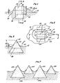
- Figure 1 is a longitudinal sectional view of a tooth improved according to the present invention.
- Figure 2 is a plan view of the tooth shown in Figure 1.
- Figure 3 is a cross sectional view taken through line 3-3 of Figure 1.
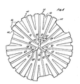
- Figure 4 is a diagrammatic plan view of a rotating bit showing a pad layout whereon a tooth configuration improved according to the present invention is disposed.
- Figure 5a is a diagrammatic plot detail diagram showing the placement of diamond cutting elements on the primary pads from the apex through the shoulder to the gage of the bit of Figure 4.
- Figure 5b is an enlarged view of a portion of the bifurcated pads of Figure 5a shown in diagrammatic form.
- Figure 6a is a diagrammatic profile in longitudinal cross section of the rotary bit shown in plan view in Figure 4.
- Figure 6b is an enlarged view of a portion of Figure 6a included within
circle 6b. - Figure 7 is a diagrammatic cross sectional view taken along line 7-7 of Figure 5b showing two sizes of PCD elements adjacently disposed in a row of teeth.
- Figure 8 is a partial diagrammatic plan view ot another embodiment of the tooth plot similar to that shown in Figure 5a wherein an alternative plot is provided on the lands.
- The present invention and its various embodiments may be better understood by viewing the above Figures in light of the following description.
- The present invention is an improvement in diamond tooth design and tooth configuration in a rotary bit. The useful life of a diamond rotating bit can be extended by using a tooth design and tooth configuration which retains the diamond cutting element on the face of the rotating cutting bit for a longer period and which maximizes the useful life of the diamond cutting element by avoiding loss and premature damage or fracture to the diamond cutting element.
- To extend the useful life of the diamond cutting element, the triangular, prismatic shaped synthetic polycrystalline diamonds are exposed to the maximum extent from the bit face of the drill. However, the farther such diamonds are exposed from the bit face, the less they are embedded and secured within the bit face. Although the degree of security and retention of such a diamond cutting element can be increased by providing an integral extension of the diamond face in the form of a trailing support, the present invention has further improved the security of retention by forming a generally oval shaped collar about the base of a generally teardrop-shaped cutting tooth having a leading face formed by the diamond cutting element and about at least a portion of the trailing support forming the tail of an otherwise teardrop-shaped tooth. Thus, the tooth in plan view as described below takes the form and appearance of a teardrop-shaped tooth having a generally ovulate collar extending about the midsection of the tooth. This allows the diamond to be exposed to the maximum extent while providing additional integral matrix material to secure the diamond to the bit face while using a minimum of such matrix material projecting from the bit face. The diamond may in fact be disposed entirely above the bit face if desired. The tooth design is better set forth in copending application entitled
- filed , Serial No. assigned to the same assignee of the present application.
- In addition, premature fracture of these maximally exposed diamond cutting elements can be avoided, particularly at the shoulder-to-gage transition, where the maximum cutting action occurs in a diamond rotary bit, by placing the most radially disposed polycrystalline diamond cutting tooth, such as described above, at a key level on the shoulder at which key level the diamond extends in a radial distance from the centerline of the rotary bit by a distance substantially equal to the distance of the diamond cutting elements on the gage of the bit. By this placement, polycrystalline diamond cutting elements in the shoulder form a smooth cutting transition to the natural diamond cutting elements on the gage.
- The present invention can be better understood by considering the above general description in the context of the Figures.
- Referring now to Figure 1, a longitudinal section of a tooth generally denoted by
reference number 10 is illustrated as taken through line 1-1 of Figure 2.Tooth 10 is particularly characterised by a polycrystallinediamond cutting element 14 in combination with matrix material integrally extending from rotary bit face 12 to form aprepad 16 and trailingsupport 18. As previously stated,prepad 16 can be deleted without departing from the teachings of the invention. The nature ofprepad 16 and trailingsupport 18 are better described in the copending application entitled , Serial No. , assigned to the same assignee. However,tooth 10 of Figure 1 differs from that described in the above denoted application by reason of an integrally formed, ovulate shapedcollar 20 extending from bit face 12 by aheight 22. - As better seen in plan outline in Figure 2,
tooth 10 has a main body portion principally characterised by a generally triangularly prismatic shapedpolycrystalline diamond element 14. Theapical edge 24 ofdiamond element 14 is illustrated in solid cutline while itssides 25 andbase 26 are shown in dotted and solid outline in Figures 1-3. Generally oval-shaped collar 20 completely circumscribes the main body oftooth 10 and in particular,diamond element 14. As better shown in longitudinal sectional view in Figure 1 and in perpendicular sectional view in Figure 3 taken through line 3-3 of Figure 1,collar 20 extends from bit face 12 by apreselected height 22 to provide additional matrix material. The matrix material is integrally formed with bit face 12 by conventional metallic casting and powder metallurgy techniques to more firmly embed diamond element 14 )within bit face 12. However, an amount ofdiamond element 14 has been extended from bit face 12 leaving predetermined portions ofelements 14 uncovered by any matrix material as best illustrated in Figure 3. However, with the addition of a minimal amount of integrally formed matrix material,collar 20 provides additional lateral, forward and rearward support toelement 14 to secureelement 14 to bitface 12. - Thus,
tooth 10 as shown in Figure 2 forms a singular geometric shape generally described as a teardrop-shaped tooth having a generally oval-shaped collar disposed around the triangular prismatic-shaped diamond element. This shape is illustrative only and any tooth design could be used with equal facility in the present invention. - Figure 1 also shows in solid outline a second, larger similar triangular prismatic shaped
diamond element 28 which has the same substantial shape aselement 14 but can be included withintooth 10 as an alternative substitute cutting element of larger dimension. Specifically,element 14 is a conventionally manufactured polycrystalline diamond stone manufacturea by General Electric Company under thetrademark GEOSET 2102, whilelarger cutting element 28 is a similarly shaped but larger polycrystalline diamond stone manufactured by General Electric Company under the trademark GEOSET 2103. Thus, thesame tooth 10 may accommodate alternately either diamond cutting element while having a similar exposure profile above bit face 12. In the case ofsmaller diamond element 14, trailingsupport 18 is integrally continued throughportion 30 to provide additional trailing support to thesmaller diamond element 14, whichportion 30 is deleted and replaced bylarger diamond element 28 in the alternative embodiment when the larger diamond is used. - The teeth improved according to the present invention are also used in an improved configuration on a rotary drilling bit as shown by way of an example in the bit face diagrammatically illustrated in plan view in Figure 4.
Rotary bit 32 is shown illustratively as a petroleum bit divided into three symmetric sectors aboutcenter 34 ofbit 32 wherein each sector is set off from the other by amain waterway 36. As is well known to the art,main waterways 36 are subdivided into a plurality ofwater courses 38 which extend from the cehter region ofbit 32 to its periphery defined by the cylindrical sides ofgage 40 ofbit 32. In aadition, a plurality ofconventional collectors 42 are provided alternatively betweenwaterways 38 in addition to symmetrically disposedjunk slots 44.Waterways 38,collectors 42, andjunk slots 44 are formed according to conventional design principles well known to the art and will not be further described here. However, it should be understood that any style rotary bit coulo be used in combination with the present invention without departing from the spirit and scope of the invention notwithstanding differences in the style or design of the hydraulic configuration of face ofbit 32. -
Gage 40 ofbit 32 is defined by a plurality of cuttingelements 46 which include diamond cutting elements affixed to or disposed ingage 40. Such elements include synthetic diamond cutting elements as well as conventional natural diamonds set within longitudinal matrix ridges integrally formed as part ofgage 40 in a conventional manner. - Consider now the diagrammatic plot detail illustrated in Figure 5a which shows the three pads generally denoted by
reference numerals pads bit 32 of Figure 4. Each of the pads 48-52 are laid out flatly in Figure 5a, although in fact the cross section ofbit 32 is actually shown from thecenterline 54 to theouter diameter 56 of the bore as illustrated in profile in Figure 6a. Pads 48-52 thus lie on the surface ofbit 32 in the cross sectional curve illustrated in Figure 6a and in the plan view as illustrated in Figure 4. Figure 5a, then, is a diagrammatic view of each of the pads of the repetitive sequence showing the placement of the diamond cutting elements, again diagrammatically shown and previously described in connection with the Figures 1-3. - Consider, for example,
pad 52 in Figure 5a.Pad 52 begins atcenter 34 ofbit 32 and extends as a single pad fromcenter 34 to approximately point 58 which is located at ornear nose 60 ofbit 32 wherepad 52 broadens and divides into two separate pads generally denoted byreference characters 52a and 52b.Pads 52a and 52b are separated by acollector 42 best shown in Figure 4.Pads 52a and 52b continue alongflank 63 andshoulder 62 ofbit 32 togage 64 and thereafter continue upwardly alonggage 64. - Referring now, for the moment, to Figure 6a, the maximum linear velocity of
bit 32, when rotated, occurs atpoint 66 just at the beginning ofgage 64. Diamond cutting elements onshoulder 62 placed just belowpoint 66 also encounter linear cutting velocities substantially near the maximum achieved bybit 32. Typically, it is the diamond cutting elements in this area that are subjected to the highest degree of wear and it is these cutting elements that usually fail first and cause bit 32 to "go put of gage". In addition, when tripping the bit in. and out of the bore, it is also these cutting elements which are often subjected to the most abuse. Sometimes a bore will swell and must be reamed by these cutters. Further, in an intentional reaming operation these cutters will bear the primary brunt of the wearing action. Reaming is an extremely abusive operation with respect to the cutting elements. Once the gage or aiameter of the bore drilled bybit 32 is established, it is highly desirable that the drill bit not further enlarge the bore diameter. Thus, diamond cutting elements placed ongage 64 ofbit 32 are designed and intended to keep the bore "in gage" and are not intended to enlarge the diameter of the bore in any manner. Thus, these gage elements do little, if any, bore cutting except where used in reaming an undersized hole. Cutting action of the rotary bit in general, and in particular to establish the diameter of the bore, is accomplished with the cutting elements on the bit face. Once these elements are lost or have their cutting action impaired in any manner, the usable life of the entire rotary bit essentially enas. - Refer again to the cutting elements of the present invention as described in connection with Figures 1-3 in the illustrated embodiment and as particularly shown in Figure 3, the extent of projection of
element 14 from bit face 12, namely distance 68, is approximately 2.6 to 2.7 millimeters when polycrystalline synthetic diamonds are used. In the illustrated embodiment, the cutting elements ingage 64 are typically chosen as industrial grade natural diamonds for economic and design reasons of a size of approximately 6-8 per carat. In other embodiments new or used PCD elements, set face or side out, may be used to better advantage. - Turn again to Figure 5a. Without the benefit of the present invention a bit with synthetic diamond elements on the face up to the gage would always be over-gage. When embeddea in
gage 64 according to conventional principles, the projection of such natural diamonds, generally denoted byreference numeral 70, is typically no more than 0.64 millimeters beyond the bit surface. As best illustrated in the enlargement of Figure 6b, if the synthetic polycrystalline diamond cutting elements onshoulder 62 were extended to point 66 next togage 64, such a diamond would extend approximately 2.7 millimeters from the bit face and the next adjacent diamond upwardly ongage 64, a natural diamond, would extend only 0.64 millimeters from the bit face. The result would be that the synthetic diamond would be substantially over-gage atpoint 66 where maximal lineal cutting velocity is incurred. Such a bit cannot be shipped to the field. - Therefore, according to the present invention as shown in Figure 6b, a
key level 72 is identified onshoulder 62 above which the synthetic polycrystalline diamond cutting elements are not positioned. Consider the enlargement of Figure 5b, where pad 48b includes a polycrystallinediamond bearing tooth 96 positioned onshoulder 62 atkey level 72. A pattern of synthetic polycrystalline diamond cutting elements are disposed belowkey level 72 as best seen in Figure 5a on pads 48-52. Abovekey level 72 and belowgage point 66,shoulder 62 is provided with a patterned array of cutting elements inkeyspace 90, generally denoted byreference numeral 88, each cutting element incorporating a natural diamond of a size of approximately 5 per carat. - turning again to Figure 6b, wherein the projection of the cutting elements from the bit face are shown in exaggerated profile,
tooth 96 is shown atkey level 72 and extends perpendicularly from the bit face ofshoulder 62 by the designed amount of approximately 6.7 millimeters. 5 per caratnatural diamonds 88 are then positioned in a transition region orkeyspace 90 onshoulder 62 togage point 66. According to the curvature of the illustrated embodiment,key level 72 is chosen so that uppermost polycrystallinesynthetic diamond tooth 96 extends radially fromcenter line 54 by an amount substantially equal to the extent ofgage teeth 70 fromcenter line 54 ofbit 32 as indicated byline 91 in Figure 6b. Thus,tooth 96 is "in gage" and no other principal cutting tooth is positioned on the bit face ofbit 32 beyond the designed gage diameter.Transition diamonds 88 thus provide a gage-type keyspace 90 transitioning into smaller 6 to 8 percarat gage diamonds 70 ongage 64. BothGEOSETS 2102 and 2103 are shown in Figure 6b with the larger 2103 GEOSET shown in dotted outline and the smaller 2102 GEOSETS shown in solid outline. Figures 5a and 5b show the GEOSETS symbolically as open triangles and circles, with the solid circles being natural diamond. Figure 6b, however, shows the diamond cutting elements in their ideal geometric shape where round natural diamonds are depicted for the sake of clarity as spherical. Clearly, other shaped diamonds could be substituted for the rounded natural diamonds. - Turning now to Figure 5a, consider again the disposition of diamonds illustrated on
pad 48. A periodic pattern of diamond types is shown belowkey level 72 onpads 48a and 48b. Circularelements representing teeth prismatic aiamond GEOSET 2102, having equilateral triangular faces of approximately 4.0 millimeters and a thickness of 2.6 millimeters.Teeth GEOSET 2102 diamond whileteeth Teeth adjacent teeth teeth pads 48a and 48b. Thereafter, polycrystalline synthetic diamond bearing teeth are placed on a single row on or near the leading edge ofpads 48a and 48b down to the point where each of these pads merge to formsingle land 48.Single pad 48 then continues with a double row of teeth on portion 118, one row being of polycrystalline synthetic material and the other row including 5 per carat natural diamond material. Thevery tip portion 116 is then heavily provided with scrap portions of polycrystalline synthetic material which are recycled from previously worn bits or set with various types of natural diamonds.Pads - Referring now to Figure 4 it can be seen that pads 48-52 are repeated about a bit face in a repetitious pattern with only three pads reproduced in full length as shown in Figure 5a. Most of the pads are truncated or shortened to provide room for
main waterways 36 ofbit 32. Bit face designs other than that shown in Figure 4 could have been used with the tooth placement of Figures 5a-b and 6a-b. For example, in other designs, pads 48-52 as shown in Figure 5a or portions thereof may be repeated only three or four times about the bit face rather than the five times illustrated in the design of Figure 4. - Refer now to Figures 5a, 5b and 6b wherein the relationship between the spacing of teeth on adjacent pads is described. Consider again Figure 5b and
bifurcated pads 52a, 52b ofpad 52 shown in its entirety in Figure 5a and in fragmentary view in Figure 5b. In Figure 5b,tooth 73 onpad 52a andtooth 74 on pad 52b are in line with each other and can be considered as the starting point or initial reference location for all other teeth on the bit as will be described in the following. The distance between two adjacent teeth in the same row on the same pad is defined as a unit of spacing and is uniform throughout the tooth configuration on the bit face. For example, the distance betweentooth tooth pad 52a. Similarly, the distance betweentooth teeth - Consider now bifurcated
pads 50a and 50b ofpad 50 shown in its entirety in Figure 5a and in fragmentary view in Figure 5b. Turning to Figure 5b,tooth 80 onpad 50a andtooth 81 on pad 50b are in line with each other and are offset away from line 1 by two-thirds of a unit space from the corresponding azimuthal level ofteeth pads 52a and 52b, respectively. Each of the azimuthal lines vertically drawn in Figure 5b are one sixth of the unit space apart. Similarly,tooth 82 onpad 48a andtooth 83 on pad 48b are in line with each other and are offset away from line 1 by one-third of a unit space from the azimuthal level ofteeth pads 52a and 52b, respectively. This pattern is repeated every three pads circumferentially around the bit. - For example,
tooth 71 onpad 52a andtooth 77 on pad 52b are in line with each other and offset fromteeth Tooth 86 onpad 50a and tooth 87 on pad 50b are similarly longitudinally offset fromtooth 80 onpad 50a andtooth 81 on pad 50b respectively by a unit spacing, and are longitudinally offset fromteeth Tooth 89 onpad 48a andtooth 92 on pad 48b are also in line with each other and are longitudinally offset fromteeth teeth - As illustrated in the Figures, and in particular in Figure 5b, a second row of teeth is provided on each bifurcated pad which second row is disposed behind and offset behind its adjacent front row of teeth just described above by one-half of a unit space. For example,
tooth 97 onpad 50a is set halfway between and behindteeth pad 50a. The teeth in the second row are set in a pattern similar to the pattern just >described. The teeth within the second row on each of the pads are related to the second row teeth on adjacent pads by offset longitudinal spacing of multiples of one-third of the unit space in the same manner as the teeth of the first row. - Teeth are disposed on the bit face according to the described pattern up to the region of
bit shoulder 62, shown in Figure 6b, untilkey point 72 is reached. However, no tooth is disposed on the bit face abovekey level 72 or betweenkey level 72 andgage 66 inkeyspace 90. Referring again to Figure 5b, it can readily be seen thatteeth pads 52a and 52b, that isnearest gage point 66.Teeth key level 72.Teeth pads 50a and 50b respectively are set one-third of a unit space belowkey level 72. Onlyteeth pads 48a and 48b respectively are set exactly atkey level 72. Therefore,teeth key level 72 occur only at the end of the cutting pattern. Therefore, beginning atkey level 72, a tooth and an aligned backup tooth is presented at every one-sixth interval of a unit space fromkey level 72 towardcenter 34 of the bit. As would be seen in an azimuthal swath cut by the bit as it rotates, the tooth density is increased twofold from six per unit space for the first rows on the three bifurcated pads to twelve per unit space over the same three bifurcated pads by the addition of the offset second row of teeth on each pad. Each repetition of the pattern thus provides redundancy of the 12 per unit space coverage of teeth. Tooth density is thus increased greatly over the density achieved by the placement of teeth in a single row on a single pad. As a result, the cutting action is smoother, more efficient, and the life of the bit is substantially increased. - The unit space between teeth as described in the above pattern was divided in thirds. Such a pattern has been described 1 here only for the purposes of illustration and it must be understood that other multiples of division could have been chosen as well without departing from the scope of the invention.
- Referring now to Figure 5a, the teeth set on pads 46-52 are further distinguished from each other by including different types of diamond material within the tooth. Therefore, tnere is a distribution of diamond-type material which is included and superimposed upon the geometric pattern of teeth described above. Consider again
tooth 73 onpad 52a in Figure 5a.Tooth 73 is illustrated in Figure 5a and 5b by a triangle to indicate thattooth 73 includes a one carat GEOSET 2103.Tooth 74 which is aligned behindtooth 73 and includea within the first row in pad 52b incluaes a one-third carat GEOSET 2102. This same alternation of diamond type material included within the teeth repeats onpads 50a and 50b withtooth 80 including aGEOSET 2102 and azimuthally alignedtooth 81, including a GEOSET 2103. Similarly,pads 48a and 4bb includetooth 82, which includes a 2102GECSET ana tooth 83 which includes GEOSET 2103. Beginning withtooth 84 on the first row onpad 52a, the pattern is reversed. In other words,tooth 84 is set with a GEOSET 2103 whiletooth 85 in the first row on pad 52b is set with aGECSET 2102. Tnis pattern is again repeated onpads 50a and 50b whereintooth 86 includes a GEOSET 2103 and aligned tooth 87 aGEOSET 2102; and onpads 48a and 48b whereintooth 89 includes a GEOSET 2103 and tooth 92 aGEOSET 2102. - The alternation ot diamond-type material included within the teeth continues across
bit shoulder 62 to one unit space past the bottom ofjunk slot 44, not illustrated in Figure 5a, but which is shown in plan view in Figure 4. - Two teatures should be noted with respect to the diamond placement pattern as shown in
land 52 on Figure 5a. Firstly,pads 52a and 52b include twoportions 100 and 101 wherein the teeth alternately include polycrystalline diamond elements of differing sizes, namely, aGEOSET 2102 diamond alternated with a GEOSET 2103 diamond. Since in each case, regardless of diamond size, the extent of the tooth projection from the bit face is identical for each tooth inportions 100 and 101, the different sized diamond elements included within the teeth result in alternating extents of disposition within the matrix material of the bit face, namely, the larger 2103 diamond is embedded more beeply than the smaller 2102 diamond. This is shown in Figure 7 in diagrammatic sectional view along line 7-7 in Figure 5b of pad 48b. Thus, a higher density of deeply embedded, large diamond cutting elements can be achieved than would otherwise be possible. In addition, the. larger diamonas tend to be more impact resistant and their fixation to the bit is more erosion resistant. Therefore, a mixed series of larger and smaller diamonds provides better performance than a similar series of only smaller diamonds, and is more economical to manufacture than a similar series of only larger diamonds. - Turning now to Figure 8, a second embodiment of a tooth or diamond plot in addition to that shown in Figure 5a is diagrammatically illustrated in symbolic plan view. The plot of 25Figure 8 differs primarily from that of Figure 5a in that the total number of alternating larger GEOSET 2103 diamonds and
smaller GEOSET 2102 diamonds set as described above in connection with Figure 7 has been increased andsecond rows rows 106 and 108, respectively, which leading rows are also shown on the pads of the plot ciagram of Figure 5a asportions 100 and 101.Rows pad 48 as encircled in dotted outline for the purposes of clarity of description. The number of larger GEOSETS 2103 inrow 106, for example, are in the embodiment of Figure 8 reduced to three in number, whereas in the corresponding row in the embodiment of Figure 5a, four such GEOSETS 2103 are used at the similar portion 100ot pad 52. The second row,row 102, corresponding to row 106 and row 104 corresponding to row 108 of diamond elements onpad 52, are positioned on the pad to lie behind and in the half spaces between the diamond elements in the preceeding row. Namely,diamond element 114 is placed behind and halfway between leadingdiamond elements - It has been found that a plot setting as shown in Figure 6 provides additional cutting capacity and bit life, particularly near
nose 60 of the bit. By using thesmaller GEOSET 2102 diamond elements alongflank 63 of the bit and doubling up the tooth rows to increase diamond density in the region ofnose 60, both improved performance and bit life can be achieved without both improved performance and bit life can be achieved without substantially increasing the number of diamond elements used in the bit and thus increasing its cost. It is believed thatnose 60 may be subject to greater abuse thanflank 63 because of the vertical weight of the drill string is supported in large part directly bynose 60. Similarly, a double row of teeth including a high proportion of larger 2103 GEOSETS is provided on the shoulder up tokey level 72 to accommodate the greater wear and abuse to which such peripherally located teeth are subjected. The remaining portions of the bit are then providea with smaller diamond elements and a lower tooth density suitable to those more lightly worn or abused portions of the bit. - Many alterations and modifications may be made by those having orainary skill in the art without departing from the spirit and scope of the present invention. For example, although the illustrated embodiment has assumed a certain bit face style distinguished by a specified configuration of nozzles, pads, waterways, and collectors as shown in more detail in Figures 4-6, any other bit face employing the principles of the present invention could also be equally employed. Thus, the illustratea embodiment has been described only for the purposes of clarification and example and should not be taken as limiting the scope of the following claims.
Claims (20)
whereby bifurcated groups of rows are formed.
0 whereby density of cutting elements is doubled within said azimuthal swath cut by said bit as said bit rotates, a cutting element being presented at each submultiple spacing within said longitudinal distance of unit space and at each point halfway between adjacent submultiple spacings. 25
5 whereby density of cutting elements is doubled within said azimuthal swath cut by said bit as said bit rotates, a cutting element being presented at each submultiple spacing within said longitudinal distance of unit space and at each point halfway between adjacent submultiple spacings. 3
Applications Claiming Priority (2)
| Application Number | Priority Date | Filing Date | Title |
|---|---|---|---|
| US496611 | 1983-05-20 | ||
| US06/496,611 US4586574A (en) | 1983-05-20 | 1983-05-20 | Cutter configuration for a gage-to-shoulder transition and face pattern |
Publications (3)
| Publication Number | Publication Date |
|---|---|
| EP0127077A2 true EP0127077A2 (en) | 1984-12-05 |
| EP0127077A3 EP0127077A3 (en) | 1986-02-05 |
| EP0127077B1 EP0127077B1 (en) | 1989-07-26 |
Family
ID=23973404
Family Applications (1)
| Application Number | Title | Priority Date | Filing Date |
|---|---|---|---|
| EP84105607A Expired EP0127077B1 (en) | 1983-05-20 | 1984-05-17 | A rotatable drill bit |
Country Status (8)
| Country | Link |
|---|---|
| US (1) | US4586574A (en) |
| EP (1) | EP0127077B1 (en) |
| JP (1) | JPS59217890A (en) |
| AU (1) | AU2806584A (en) |
| BR (1) | BR8402398A (en) |
| CA (1) | CA1214771A (en) |
| DE (1) | DE3479142D1 (en) |
| ZA (1) | ZA843409B (en) |
Cited By (12)
| Publication number | Priority date | Publication date | Assignee | Title |
|---|---|---|---|---|
| EP0156235A2 (en) * | 1984-03-26 | 1985-10-02 | Eastman Christensen Company | Multi-component cutting element using consolidated rod-like polycrystalline diamond |
| EP0156264A2 (en) * | 1984-03-26 | 1985-10-02 | Eastman Christensen Company | Multi-component cutting element using triangular, rectangular and higher order polyhedral-shaped polycrystalline diamond disks |
| EP0157278A2 (en) * | 1984-03-26 | 1985-10-09 | Eastman Christensen Company | Multi-component cutting element using polycrystalline diamond disks |
| EP0189212A1 (en) * | 1985-01-25 | 1986-07-30 | Eastman Christensen Company | An improved kerfing drag bit |
| EP0236924A2 (en) * | 1986-03-07 | 1987-09-16 | Eastman Teleco Company | Diamond setting in a cutting tooth in a drill bit with an increased effective diamond width |
| EP0265718A2 (en) * | 1986-10-16 | 1988-05-04 | Eastman Teleco Company | An improved bit design for a rotating bit incorporating synthetic polycrystalline cutters |
| EP0325271A2 (en) * | 1988-01-20 | 1989-07-26 | Eastman Teleco Company | Drill bit |
| US5649604A (en) * | 1994-10-15 | 1997-07-22 | Camco Drilling Group Limited | Rotary drill bits |
| GB2294069B (en) * | 1994-10-15 | 1998-10-28 | Camco Drilling Group Ltd | Improvements in or relating to rotary drills bits |
| GB2352748A (en) * | 1999-08-05 | 2001-02-07 | Smith International | Side-cutting drill bit |
| GB2359572A (en) * | 2000-01-11 | 2001-08-29 | Baker Hughes Inc | Anti-whirl drill bit |
| US6684967B2 (en) | 1999-08-05 | 2004-02-03 | Smith International, Inc. | Side cutting gage pad improving stabilization and borehole integrity |
Families Citing this family (26)
| Publication number | Priority date | Publication date | Assignee | Title |
|---|---|---|---|---|
| US4673044A (en) * | 1985-08-02 | 1987-06-16 | Eastman Christensen Co. | Earth boring bit for soft to hard formations |
| US4883136A (en) * | 1986-09-11 | 1989-11-28 | Eastman Christensen Co. | Large compact cutter rotary drill bit utilizing directed hydraulics for each cutter |
| US5025873A (en) * | 1989-09-29 | 1991-06-25 | Baker Hughes Incorporated | Self-renewing multi-element cutting structure for rotary drag bit |
| US5467836A (en) * | 1992-01-31 | 1995-11-21 | Baker Hughes Incorporated | Fixed cutter bit with shear cutting gage |
| US5282513A (en) * | 1992-02-04 | 1994-02-01 | Smith International, Inc. | Thermally stable polycrystalline diamond drill bit |
| US5238075A (en) * | 1992-06-19 | 1993-08-24 | Dresser Industries, Inc. | Drill bit with improved cutter sizing pattern |
| GB9422022D0 (en) * | 1994-10-31 | 1994-12-21 | Red Baron Oil Tools Rental | Two stage underreamer |
| US6206117B1 (en) | 1997-04-02 | 2001-03-27 | Baker Hughes Incorporated | Drilling structure with non-axial gage |
| US6123160A (en) * | 1997-04-02 | 2000-09-26 | Baker Hughes Incorporated | Drill bit with gage definition region |
| US6321862B1 (en) * | 1997-09-08 | 2001-11-27 | Baker Hughes Incorporated | Rotary drill bits for directional drilling employing tandem gage pad arrangement with cutting elements and up-drill capability |
| US20060011388A1 (en) * | 2003-01-31 | 2006-01-19 | Mohammed Boudrare | Drill bit and cutter element having multiple extensions |
| US6929079B2 (en) * | 2003-02-21 | 2005-08-16 | Smith International, Inc. | Drill bit cutter element having multiple cusps |
| US6883624B2 (en) * | 2003-01-31 | 2005-04-26 | Smith International, Inc. | Multi-lobed cutter element for drill bit |
| US7690442B2 (en) * | 2005-05-17 | 2010-04-06 | Smith International, Inc. | Drill bit and cutting inserts for hard/abrasive formations |
| US7757789B2 (en) * | 2005-06-21 | 2010-07-20 | Smith International, Inc. | Drill bit and insert having bladed interface between substrate and coating |
| US7624825B2 (en) * | 2005-10-18 | 2009-12-01 | Smith International, Inc. | Drill bit and cutter element having aggressive leading side |
| US7743855B2 (en) * | 2006-09-05 | 2010-06-29 | Smith International, Inc. | Drill bit with cutter element having multifaceted, slanted top cutting surface |
| US7798258B2 (en) * | 2007-01-03 | 2010-09-21 | Smith International, Inc. | Drill bit with cutter element having crossing chisel crests |
| US7631709B2 (en) | 2007-01-03 | 2009-12-15 | Smith International, Inc. | Drill bit and cutter element having chisel crest with protruding pilot portion |
| US7686106B2 (en) * | 2007-01-03 | 2010-03-30 | Smith International, Inc. | Rock bit and inserts with wear relief grooves |
| US8205692B2 (en) * | 2007-01-03 | 2012-06-26 | Smith International, Inc. | Rock bit and inserts with a chisel crest having a broadened region |
| US8544568B2 (en) * | 2010-12-06 | 2013-10-01 | Varel International, Inc., L.P. | Shoulder durability enhancement for a PDC drill bit using secondary and tertiary cutting elements |
| US8607899B2 (en) | 2011-02-18 | 2013-12-17 | National Oilwell Varco, L.P. | Rock bit and cutter teeth geometries |
| US20140182947A1 (en) | 2012-12-28 | 2014-07-03 | Smith International, Inc. | Cutting insert for percussion drill bit |
| CA3143814A1 (en) | 2015-01-12 | 2016-07-21 | Longyear Tm, Inc. | Drilling tools having matrices with carbide-forming alloys, and methods of making and using same |
| WO2017123562A1 (en) | 2016-01-13 | 2017-07-20 | Schlumberger Technology Corporation | Angled chisel insert |
Citations (8)
| Publication number | Priority date | Publication date | Assignee | Title |
|---|---|---|---|---|
| US3135341A (en) * | 1960-10-04 | 1964-06-02 | Christensen Diamond Prod Co | Diamond drill bits |
| US3709308A (en) * | 1970-12-02 | 1973-01-09 | Christensen Diamond Prod Co | Diamond drill bits |
| GB1367520A (en) * | 1971-11-19 | 1974-09-18 | Shell Int Research | Diamond bit |
| US4073354A (en) * | 1976-11-26 | 1978-02-14 | Christensen, Inc. | Earth-boring drill bits |
| US4234048A (en) * | 1978-06-12 | 1980-11-18 | Christensen, Inc. | Drill bits embodying impregnated segments |
| US4373593A (en) * | 1979-03-16 | 1983-02-15 | Christensen, Inc. | Drill bit |
| EP0117506A2 (en) * | 1983-02-24 | 1984-09-05 | Eastman Christensen Company | A cutting tooth and a rotating bit having a fully exposed polycrystalline diamond element |
| EP0121124A2 (en) * | 1983-03-07 | 1984-10-10 | Eastman Christensen Company | An improved diamond cutting element in a rotating bit |
Family Cites Families (1)
| Publication number | Priority date | Publication date | Assignee | Title |
|---|---|---|---|---|
| US3727704A (en) * | 1971-03-17 | 1973-04-17 | Christensen Diamond Prod Co | Diamond drill bit |
-
1983
- 1983-05-20 US US06/496,611 patent/US4586574A/en not_active Expired - Lifetime
-
1984
- 1984-05-07 ZA ZA843409A patent/ZA843409B/en unknown
- 1984-05-16 AU AU28065/84A patent/AU2806584A/en not_active Abandoned
- 1984-05-17 DE DE8484105607T patent/DE3479142D1/en not_active Expired
- 1984-05-17 EP EP84105607A patent/EP0127077B1/en not_active Expired
- 1984-05-18 BR BR8402398A patent/BR8402398A/en unknown
- 1984-05-18 CA CA000454663A patent/CA1214771A/en not_active Expired
- 1984-05-19 JP JP59099730A patent/JPS59217890A/en active Pending
Patent Citations (8)
| Publication number | Priority date | Publication date | Assignee | Title |
|---|---|---|---|---|
| US3135341A (en) * | 1960-10-04 | 1964-06-02 | Christensen Diamond Prod Co | Diamond drill bits |
| US3709308A (en) * | 1970-12-02 | 1973-01-09 | Christensen Diamond Prod Co | Diamond drill bits |
| GB1367520A (en) * | 1971-11-19 | 1974-09-18 | Shell Int Research | Diamond bit |
| US4073354A (en) * | 1976-11-26 | 1978-02-14 | Christensen, Inc. | Earth-boring drill bits |
| US4234048A (en) * | 1978-06-12 | 1980-11-18 | Christensen, Inc. | Drill bits embodying impregnated segments |
| US4373593A (en) * | 1979-03-16 | 1983-02-15 | Christensen, Inc. | Drill bit |
| EP0117506A2 (en) * | 1983-02-24 | 1984-09-05 | Eastman Christensen Company | A cutting tooth and a rotating bit having a fully exposed polycrystalline diamond element |
| EP0121124A2 (en) * | 1983-03-07 | 1984-10-10 | Eastman Christensen Company | An improved diamond cutting element in a rotating bit |
Cited By (23)
| Publication number | Priority date | Publication date | Assignee | Title |
|---|---|---|---|---|
| EP0156264A2 (en) * | 1984-03-26 | 1985-10-02 | Eastman Christensen Company | Multi-component cutting element using triangular, rectangular and higher order polyhedral-shaped polycrystalline diamond disks |
| EP0157278A2 (en) * | 1984-03-26 | 1985-10-09 | Eastman Christensen Company | Multi-component cutting element using polycrystalline diamond disks |
| EP0156235A3 (en) * | 1984-03-26 | 1986-06-11 | Norton Christensen, Inc. | Multi-component cutting element using consolidated rod-like polycrystalline diamond |
| EP0157278A3 (en) * | 1984-03-26 | 1986-06-11 | Norton Christensen, Inc. | Multi-component cutting element using polycrystalline diamond disks |
| EP0156264A3 (en) * | 1984-03-26 | 1986-06-11 | Norton Christensen, Inc. | Multi-component cutting element using triangular, rectangular and higher order polyhedral-shaped polycrystalline diamond disks |
| EP0156235A2 (en) * | 1984-03-26 | 1985-10-02 | Eastman Christensen Company | Multi-component cutting element using consolidated rod-like polycrystalline diamond |
| EP0189212A1 (en) * | 1985-01-25 | 1986-07-30 | Eastman Christensen Company | An improved kerfing drag bit |
| EP0236924A2 (en) * | 1986-03-07 | 1987-09-16 | Eastman Teleco Company | Diamond setting in a cutting tooth in a drill bit with an increased effective diamond width |
| EP0236924A3 (en) * | 1986-03-07 | 1989-02-08 | Eastman Christensen Company | Diamond setting in a cutting tooth in a drill bit with an increased effective diamond width |
| EP0265718A3 (en) * | 1986-10-16 | 1989-10-25 | Eastman Christensen Company | An improved bit design for a rotating bit incorporating synthetic polycrystalline cutters |
| EP0265718A2 (en) * | 1986-10-16 | 1988-05-04 | Eastman Teleco Company | An improved bit design for a rotating bit incorporating synthetic polycrystalline cutters |
| EP0325271A2 (en) * | 1988-01-20 | 1989-07-26 | Eastman Teleco Company | Drill bit |
| EP0325271A3 (en) * | 1988-01-20 | 1990-01-31 | Eastman Christensen Company | Methods and apparatus for establishing hydraulic flow regime in drill bits |
| US5649604A (en) * | 1994-10-15 | 1997-07-22 | Camco Drilling Group Limited | Rotary drill bits |
| GB2294069B (en) * | 1994-10-15 | 1998-10-28 | Camco Drilling Group Ltd | Improvements in or relating to rotary drills bits |
| GB2352748A (en) * | 1999-08-05 | 2001-02-07 | Smith International | Side-cutting drill bit |
| US6253863B1 (en) | 1999-08-05 | 2001-07-03 | Smith International, Inc. | Side cutting gage pad improving stabilization and borehole integrity |
| GB2352748B (en) * | 1999-08-05 | 2004-01-07 | Smith International | Drill bit |
| US6684967B2 (en) | 1999-08-05 | 2004-02-03 | Smith International, Inc. | Side cutting gage pad improving stabilization and borehole integrity |
| GB2359572A (en) * | 2000-01-11 | 2001-08-29 | Baker Hughes Inc | Anti-whirl drill bit |
| BE1014019A5 (en) * | 2000-01-11 | 2003-02-04 | Baker Hughes Inc | DRILL BIT WITH LIMIT OF SIDE MOVEMENT AND SUBTERRANEAN DRILLING METHOD. |
| US6575256B1 (en) | 2000-01-11 | 2003-06-10 | Baker Hughes Incorporated | Drill bit with lateral movement mitigation and method of subterranean drilling |
| GB2359572B (en) * | 2000-01-11 | 2004-05-26 | Baker Hughes Inc | Drill bit with lateral movement mitigation and method of subterranean drilling |
Also Published As
| Publication number | Publication date |
|---|---|
| CA1214771A (en) | 1986-12-02 |
| JPS59217890A (en) | 1984-12-08 |
| EP0127077A3 (en) | 1986-02-05 |
| DE3479142D1 (en) | 1989-08-31 |
| US4586574A (en) | 1986-05-06 |
| AU2806584A (en) | 1984-11-22 |
| EP0127077B1 (en) | 1989-07-26 |
| ZA843409B (en) | 1985-07-31 |
| BR8402398A (en) | 1985-04-02 |
Similar Documents
| Publication | Publication Date | Title |
|---|---|---|
| US4586574A (en) | Cutter configuration for a gage-to-shoulder transition and face pattern | |
| CA1206470A (en) | Tooth configuration for an earth boring bit | |
| US4529047A (en) | Cutting tooth and a rotating bit having a fully exposed polycrystalline diamond element | |
| US4512426A (en) | Rotating bits including a plurality of types of preferential cutting elements | |
| US4673044A (en) | Earth boring bit for soft to hard formations | |
| US6009963A (en) | Superabrasive cutting element with enhanced stiffness, thermal conductivity and cutting efficiency | |
| US4889017A (en) | Rotary drill bit for use in drilling holes in subsurface earth formations | |
| EP0164297B1 (en) | Diamond drill bit with varied cutting elements | |
| US4550790A (en) | Diamond rotating bit | |
| US4491188A (en) | Diamond cutting element in a rotating bit | |
| US9038752B2 (en) | Rotary drag bit | |
| EP0186408B1 (en) | Improvements in or relating to cutting elements for rotary drill bits | |
| EP0291314A2 (en) | Cutting structure and rotary drill bit comprising such a structure | |
| CA1218353A (en) | Tooth design to avoid shearing stresses | |
| CA1248939A (en) | Exposed polycrystalline diamond mounted in a matrix body drill bit | |
| CA1218355A (en) | Tooth design using cylindrical diamond cutting elements | |
| EP0370199A1 (en) | Drill bits utilizing polycrystalline diamond grit | |
| CA1256856A (en) | Earth boring bit for soft to hard formations | |
| JPS6332955B2 (en) |
Legal Events
| Date | Code | Title | Description |
|---|---|---|---|
| PUAI | Public reference made under article 153(3) epc to a published international application that has entered the european phase |
Free format text: ORIGINAL CODE: 0009012 |
|
| AK | Designated contracting states |
Designated state(s): BE CH DE FR GB LI NL |
|
| PUAL | Search report despatched |
Free format text: ORIGINAL CODE: 0009013 |
|
| AK | Designated contracting states |
Designated state(s): BE CH DE FR GB LI NL |
|
| 17P | Request for examination filed |
Effective date: 19860422 |
|
| 17Q | First examination report despatched |
Effective date: 19870721 |
|
| RAP1 | Party data changed (applicant data changed or rights of an application transferred) |
Owner name: EASTMAN CHRISTENSEN COMPANY |
|
| GRAA | (expected) grant |
Free format text: ORIGINAL CODE: 0009210 |
|
| AK | Designated contracting states |
Kind code of ref document: B1 Designated state(s): BE CH DE FR GB LI NL |
|
| REF | Corresponds to: |
Ref document number: 3479142 Country of ref document: DE Date of ref document: 19890831 |
|
| ET | Fr: translation filed | ||
| RBV | Designated contracting states (corrected) |
Designated state(s): BE DE FR GB NL |
|
| REG | Reference to a national code |
Ref country code: CH Ref legal event code: PL |
|
| PLBE | No opposition filed within time limit |
Free format text: ORIGINAL CODE: 0009261 |
|
| STAA | Information on the status of an ep patent application or granted ep patent |
Free format text: STATUS: NO OPPOSITION FILED WITHIN TIME LIMIT |
|
| 26N | No opposition filed | ||
| PGFP | Annual fee paid to national office [announced via postgrant information from national office to epo] |
Ref country code: DE Payment date: 19920410 Year of fee payment: 9 |
|
| PGFP | Annual fee paid to national office [announced via postgrant information from national office to epo] |
Ref country code: NL Payment date: 19920531 Year of fee payment: 9 |
|
| PG25 | Lapsed in a contracting state [announced via postgrant information from national office to epo] |
Ref country code: NL Effective date: 19931201 |
|
| NLV4 | Nl: lapsed or anulled due to non-payment of the annual fee | ||
| PG25 | Lapsed in a contracting state [announced via postgrant information from national office to epo] |
Ref country code: DE Effective date: 19940201 |
|
| PGFP | Annual fee paid to national office [announced via postgrant information from national office to epo] |
Ref country code: FR Payment date: 19940413 Year of fee payment: 11 |
|
| PG25 | Lapsed in a contracting state [announced via postgrant information from national office to epo] |
Ref country code: FR Effective date: 19960229 |
|
| REG | Reference to a national code |
Ref country code: FR Ref legal event code: ST |
|
| REG | Reference to a national code |
Ref country code: FR Ref legal event code: ST |
|
| REG | Reference to a national code |
Ref country code: GB Ref legal event code: IF02 |
|
| PGFP | Annual fee paid to national office [announced via postgrant information from national office to epo] |
Ref country code: GB Payment date: 20020508 Year of fee payment: 19 |
|
| PGFP | Annual fee paid to national office [announced via postgrant information from national office to epo] |
Ref country code: BE Payment date: 20020606 Year of fee payment: 19 |
|
| PG25 | Lapsed in a contracting state [announced via postgrant information from national office to epo] |
Ref country code: GB Free format text: LAPSE BECAUSE OF NON-PAYMENT OF DUE FEES Effective date: 20030517 |
|
| PG25 | Lapsed in a contracting state [announced via postgrant information from national office to epo] |
Ref country code: BE Free format text: LAPSE BECAUSE OF NON-PAYMENT OF DUE FEES Effective date: 20030531 |
|
| BERE | Be: lapsed |
Owner name: *EASTMAN CHRISTENSEN CY Effective date: 20030531 |
|
| GBPC | Gb: european patent ceased through non-payment of renewal fee |
Effective date: 20030517 |