EP0126469A2 - Optical light spot scanning device for a photosensitive web material in optical photocomposing machines - Google Patents
Optical light spot scanning device for a photosensitive web material in optical photocomposing machines Download PDFInfo
- Publication number
- EP0126469A2 EP0126469A2 EP84105717A EP84105717A EP0126469A2 EP 0126469 A2 EP0126469 A2 EP 0126469A2 EP 84105717 A EP84105717 A EP 84105717A EP 84105717 A EP84105717 A EP 84105717A EP 0126469 A2 EP0126469 A2 EP 0126469A2
- Authority
- EP
- European Patent Office
- Prior art keywords
- laser beam
- rotating mirror
- axis
- segment
- laser
- Prior art date
- Legal status (The legal status is an assumption and is not a legal conclusion. Google has not performed a legal analysis and makes no representation as to the accuracy of the status listed.)
- Granted
Links
Images

Classifications
-
- H—ELECTRICITY
- H04—ELECTRIC COMMUNICATION TECHNIQUE
- H04N—PICTORIAL COMMUNICATION, e.g. TELEVISION
- H04N1/00—Scanning, transmission or reproduction of documents or the like, e.g. facsimile transmission; Details thereof
- H04N1/04—Scanning arrangements, i.e. arrangements for the displacement of active reading or reproducing elements relative to the original or reproducing medium, or vice versa
- H04N1/06—Scanning arrangements, i.e. arrangements for the displacement of active reading or reproducing elements relative to the original or reproducing medium, or vice versa using cylindrical picture-bearing surfaces, i.e. scanning a main-scanning line substantially perpendicular to the axis and lying in a curved cylindrical surface
- H04N1/0607—Scanning a concave surface, e.g. with internal drum type scanners
- H04N1/0621—Scanning a concave surface, e.g. with internal drum type scanners using a picture-bearing surface stationary in the main-scanning direction
- H04N1/0635—Scanning a concave surface, e.g. with internal drum type scanners using a picture-bearing surface stationary in the main-scanning direction using oscillating or rotating mirrors
-
- B—PERFORMING OPERATIONS; TRANSPORTING
- B41—PRINTING; LINING MACHINES; TYPEWRITERS; STAMPS
- B41B—MACHINES OR ACCESSORIES FOR MAKING, SETTING, OR DISTRIBUTING TYPE; TYPE; PHOTOGRAPHIC OR PHOTOELECTRIC COMPOSING DEVICES
- B41B19/00—Photoelectronic composing machines
-
- H—ELECTRICITY
- H04—ELECTRIC COMMUNICATION TECHNIQUE
- H04N—PICTORIAL COMMUNICATION, e.g. TELEVISION
- H04N1/00—Scanning, transmission or reproduction of documents or the like, e.g. facsimile transmission; Details thereof
- H04N1/04—Scanning arrangements, i.e. arrangements for the displacement of active reading or reproducing elements relative to the original or reproducing medium, or vice versa
- H04N1/06—Scanning arrangements, i.e. arrangements for the displacement of active reading or reproducing elements relative to the original or reproducing medium, or vice versa using cylindrical picture-bearing surfaces, i.e. scanning a main-scanning line substantially perpendicular to the axis and lying in a curved cylindrical surface
- H04N1/0657—Scanning a transparent surface, e.g. reading a transparency original
-
- H—ELECTRICITY
- H04—ELECTRIC COMMUNICATION TECHNIQUE
- H04N—PICTORIAL COMMUNICATION, e.g. TELEVISION
- H04N1/00—Scanning, transmission or reproduction of documents or the like, e.g. facsimile transmission; Details thereof
- H04N1/04—Scanning arrangements, i.e. arrangements for the displacement of active reading or reproducing elements relative to the original or reproducing medium, or vice versa
- H04N1/06—Scanning arrangements, i.e. arrangements for the displacement of active reading or reproducing elements relative to the original or reproducing medium, or vice versa using cylindrical picture-bearing surfaces, i.e. scanning a main-scanning line substantially perpendicular to the axis and lying in a curved cylindrical surface
- H04N1/0671—Scanning arrangements, i.e. arrangements for the displacement of active reading or reproducing elements relative to the original or reproducing medium, or vice versa using cylindrical picture-bearing surfaces, i.e. scanning a main-scanning line substantially perpendicular to the axis and lying in a curved cylindrical surface with sub-scanning by translational movement of the main-scanning components
- H04N1/0678—Scanning arrangements, i.e. arrangements for the displacement of active reading or reproducing elements relative to the original or reproducing medium, or vice versa using cylindrical picture-bearing surfaces, i.e. scanning a main-scanning line substantially perpendicular to the axis and lying in a curved cylindrical surface with sub-scanning by translational movement of the main-scanning components using a lead-screw or worm
Definitions
- the invention relates to an optical light spot scanning device in photosetters for a photosensitive sheet material with a modulated laser for generating a modulated laser beam, with a circular-cylindrical segment-like holder for the sheet material, for holding the sheet material in a partially cylindrical shape with a slide that can be moved parallel to the axis of the circular-segment-like holder, which carries an imaging optics and a rotating mirror arrangement, the axis of rotation of which coincides with the axis of the circular-segment-like holder, the laser beam falling via the imaging optics onto the rotating mirror arrangement and radially directed after reflection on the rotating mirror arrangement towards the sheet material by the rotation of the rotating mirror arrangement and displacement of the slide the sheet material scanned line by line and, by suitable modulation of the laser beam, generates a desired latent pattern on the material.
- a light spot scanning device of this type is known from DE-OS 31 26 642 and has some advantages over the light spot scanning devices previously used in photo setting devices.
- optical light spot scanning devices eg DE-OS 30 47 813
- complex optical correction devices are generally required in order to properly expose the photosensitive web material arranged in one plane.
- the photosensitive web material in these previously known optical light spot scanning devices is exposed in a planar arrangement because it is first transferred from the roll of material into a recording cassette and only then exposed.
- the laser beam scans the flat web material located in the receiving cassette line by line transversely to its longitudinal direction, which can be done in both directions on one or more lines.
- the text in columns or compositions can also be exposed line by line from top to bottom and thus set.
- the object of the present invention is to develop the device mentioned at the outset in such a way that a simple and uncomplicated way ensures a sharp, flawless and exact image of the quality of the laser light spot on the photosensitive material and, at the same time, a compact structure, even in the case of photosetters which are in the form of a web with photosensitive material work, whereby exposure of the sheet material over a circumferential angle of about 180 ° should be possible.
- the invention proposes that the laser is arranged on the carriage and preferably that the laser, the imaging optics and any existing parts deflecting the laser beam are mounted in a flat arrangement on the carriage, which is substantially parallel to one of the both ends of the plane containing the circular cylinder segment-like plane.
- the entire optical geometry remains fixed during the scanning, so that blurring cannot occur due to changing optical geometry. Also gradually led Lich diverging of the laser beam with increasing distance from the laser to no reduction in imaging quality, since with the arrangement according to the invention the optical distance between the laser and the material to be exposed remains constant, and any divergence that may be present can be corrected by means of a simple correction lens. Furthermore, different vibrations of the laser with respect to the carriage can no longer occur, since the laser is connected to the carriage, so that blurring due to this origin does not occur.
- the imaging optics and any existing parts deflecting the laser beam in a flat arrangement on the slide which runs essentially parallel to a plane that maintains the two ends of the circular segment-like holder the device becomes more compact, and not just because of the laser no longer lies away from the sled, but because the sled and the parts mounted on it can be housed in a flat construction on the bottom of the holder to save space.
- the laser beam can therefore be focused precisely on the photosensitive layer.
- a particularly favorable arrangement of the individual elements on the slide is characterized in that the laser next to the rotating mirror arrangement and essentially parallel to its axis of rotation, then a 90 ° deflecting mirror, then a laser modulator, another 90 ° deflecting mirror, possibly a correction lens and Finally, on the side of the rotating mirror arrangement facing away from the laser, a deflection element, which directs the laser beam to the rotating mirror arrangement, is arranged on the carriage.
- the laser beam preferably strikes the rotating mirror arrangement in a direction that coincides with the axis of the circular segment-like holder.
- the rotating mirror arrangement preferably has a rotating mirror, with a flat mirror surface enclosing an angle of 45 ° to the axis of the circular segment-like holder.
- the rotational axis of the rotary mirror arrangement lies above the laterally adjacent parts on the carriage to achieve an effective sampling or exposure of the sheet material over a circumferential angle of 18 0 0 or even more.
- This arrangement of the rotating mirror can be achieved in that either there are free spaces to the left and right of the rotating mirror or that the laser beam is first displaced upwards before hitting the rotating mirror.
- This can be done in that the laser beam is directed onto the rotating mirror by a prism which is tilted in its plane with respect to the slide and which causes an approximately 180 ° deflection of the laser beam.
- the material is in the form of a web which comes from a donor cassette arranged at one end of the holder designed as a circular cylinder segment, is guided along the circular cylinder segment and is received by a slave cassette at the other end of the holder becomes.
- the donor and slave cassettes can be accommodated in a space-saving manner without significantly increasing the overall dimensions of the device.
- the circular cylinder segment is advantageously transparent and the web material is laid around the outside of the cylinder segment.
- the circular cylinder segment thus specifies the shape of the flexible web material.
- the circular cylinder segment extends over an angle 100 to 18 0 ° and in particular about 180 °.
- the circular cylinder segment consists of a glass cylinder cut-out which extends in the circumferential direction by approximately 180 °.
- the longitudinal axis of the web material runs in a circle along the circular cylinder segment.
- the web material is to be guided in its longitudinal direction around the circular cylinder segment, so that the longitudinal axis and longitudinal lines parallel to it run parallel to peripheral or circumferential lines of the circular cylinder segment.
- lines perpendicular to the longitudinal axis and lying in the web material surface run parallel to the generatrices of the circular cylinder segment or to the cylinder segment axis.
- pairs of web material introduction and discharge rollers running parallel to the cylinder segment axis should be provided on the circumferential ends of the circular cylinder segment.
- At least the pairs of discharge rollers should be motor-driven.
- the pairs of insertion rollers are preferably also driven by a motor.
- the design according to the invention makes it possible for the insertion roller pairs and the removal roller pairs to be divided in their longitudinal direction into a plurality of differently drivable or idling sections.
- a particularly advantageous property of the device according to the invention is used, which consists in the fact that the format width does not matter.
- the device is designed for the widest possible format, it is possible to feed two different photosensitive web materials through the device in the same or different material width. This is very important, for example, in the event that the correction on paper and the final exposure on film for transmission on an offset plate.
- the roller pairs then have, for example, a common core of 500 mm width, a section being 250 mm wide and being driven by a motor.
- At least one donor or slave cassette is expediently arranged in front of or after the pair of introduction rollers or the pair of discharge rollers.
- the arrangement should be such that the width of the cassettes is equal to the width of a section or a number of adjacent sections.
- a further embodiment is designed in such a way that a cassette receiving space which can be reduced to smaller cassette sizes and which is designed to accommodate the largest possible cassette size is provided for accommodating donor cassettes or slave cassettes of different sizes.
- a cutting device is expediently connected between the removal roller pairs and the slave cassette or the slave cassettes.
- an opaque guide cover is placed around the outside of the circular cylinder segment at a distance from it.
- a further embodiment provides that the guide cover is attached so that it can be pivoted upward about a pivot axis running parallel to the cylinder segment axis.
- a circular cylinder segment 12 made of glass extends over its cylinder segment axis 16 above it over an angle of 120 °.
- the circular cylinder segment 12 is mounted in plastic strips 34 (FIG. 2), which in turn are attached to the frame 36 of the device by means of sheet metal supports 35 which extend essentially radially. !
- a likewise circular cylindrical segment-shaped guide cover 32 which according to FIG. 2 is pivotally mounted in the area of the left circumferential end of the circular cylinder segment 12 about a pivot axis 33 running parallel to the cylinder segment axis 16, so that the guide cover 32 is opened upwards in the direction of arrow f in FIG. 2 can be provided that the cover 37 of the device was previously removed or opened.
- control panel 38 on the front of the device.
- an insertion roller pair 25 is provided directly in front of the circular cylinder segment 12, the axes of which extend parallel to the cylinder segment axis 16.
- a pair of discharge rollers 26 is accommodated at the opposite circumferential end of the circular cylinder segment 12 in the front region of the device.
- cassette receiving spaces 29, 30 are provided, in which donor cassettes 27 or slave cassettes 28 of different sizes can be accommodated.
- the overall device is only about 75 cm deep and almost 50 cm high.
- the width (Fig. 1) is approximately 70 cm. This is based on a large-format exposure area of 500 x 600 mm.
- the circumference of the circular cylinder segment is 12 600 mm, while the axial extension of the circular cylinder segment is 12 500 mm.
- Photosensitive web material 11 is unwound from the donor cassette 27 and placed around the circular cylinder segment 12. Here, the web material 11 is passed through the pair of insertion rollers 25 and the pair of discharge rollers 26. It then finally arrives in the slave cassette 28, where it is rolled up again.
- a cutting device 31 which consists of a knife which can be moved in the transverse direction of the web in the direction of the arrow F (FIG. 1), in order to do so in the Slave cassette 28 to separate the photosensitive web material from the web material still resting on the cylinder segment 12.
- the pair of introduction rollers 25 and the pair of discharge rollers 26 each have three sections 25a, 25b, 25c and 26a, 26b, 26c.
- the roller pairs 25a, 26a on the left in FIG. 1 are each driven by motors 41, 42.
- the drive acts on only one, namely the inner roller of the pair of rollers.
- roller pairs 25a, 26a expediently have a length of 250 mm. This is followed by a short roller pair section 25b, 26b with a length of approximately 70 mm. This roller pair section is not driven, but runs freely. At the end there are again roller pair sections 25c, 26c which are driven by motors 43 and 44, respectively. In this case too, only the inner roller section is driven by one of the motors 43, 44.
- the drawing shows how a photosensitive web material with a width of 205 mm is guided through the first roller pair sections 25a and 26a around the left half of the circular cylinder segment 12.
- the guide cover 32 is partially broken away to illustrate the web material 11.
- a phototransistor 50 is fastened to the carriage via an arm 49 and cooperates with marks (not shown) on the front circumferential edge of the circular cylinder segment 12 in order to synchronize the movement of the carriage 24 in the axial direction with the scanning movement of the laser beam 13 to be described.
- the carriage is driven in the axial direction 16 by a spindle 51 which is rotatably arranged in a nut 52 (FIG. 2) attached to the carriage 24.
- a motor 53 (FIG. 1) drives the spindle 51 in a controlled manner to rotate.
- a laser 18 is arranged on the carriage 24 parallel to the cylinder segment axis 16, which laser emits a light beam parallel to the cylinder segment axis 16 to a - 90 ° deflection mirror 19 which directs the laser beam inwards to a laser modulator 20.
- the laser beam modulated in the sense of the typeface to be generated then arrives at a further 90 ° deflection mirror 21, which gives the beam a new 90 ° deflection, so that it again runs parallel but opposite to the beam emerging from the laser 18.
- the beam then passes through a correction lens 22 to a third 90 ° deflection mirror 23, which deflects the laser beam again in the direction of the laser 18.
- a rotating mirror 15 Between the laser 18 and the deflecting mirror 23 there is a rotating mirror 15, the axis of rotation 54 of which coincides with the cylinder segment axis 16 and lies in the mirror surface 14.
- a motor 55 drives the rotating mirror 15 to rotate continuously. In this way, a radially extending laser beam 13 is directed onto the inward-facing photosensitive layer of the photosensitive web material 11.
- the two positions of the rotating mirror 15 are separated by an angle of 60 °. which correspond to the two extreme angular positions of the radial laser beam 13.
- the photosensitive web material 11 between the two extreme positions shown in FIG. 2 is continuously scanned by the laser beam 13.
- the slide 24 By advancing the slide 24 a small distance after each angular scan by means of the rotating mirror 15, the entire width of the web material 11 can be scanned by the laser beam 13 in columns.
- a latent image is then generated on the photosensitive web material, as is indicated schematically at 56 in FIG. 1.
- central longitudinal axis 17 of the web material is placed in a circle around the circular cylinder segment 12, so that the photographic material is arranged in its natural bending direction and exposed in this position without errors.
- the web material is pulled off the donor cassette 27 and placed around the circular cylinder segment 12.
- the photosensitive web material 11 for carrying out the exposure is then at rest.
- the electronics controlling the deflection of the laser beam 13 and the advancement of the slide 24 it is possible due to a suitable memory organization to pre-sort the text and image parts to be exposed in such a way that, using suitable programming, the images are not only in the form shown in the drawing be exposed in the feed direction of the photosensitive web material, but also in a direction 90 ° to the scanning direction of the laser beam, ie in the axial direction.
- the carriage 24 With the photosensitive web material running in and wrapped around the circular cylinder segment 12, the carriage 24 begins the continuous exposure in the front right corner in the illustration in FIG. 1.
- the scanning laser beam 13 is synchronized by the phototransistor 50 connected to the carriage 24.
- the carriage moves continuously or step by step during the exposure process according to FIGS. 1 and 2 from front to back.
- the carriage 24 can also be driven by a steel belt.
- the use of a single mirror 15 has opposite polygon prisms or S piegelziern the advantage that the beam can be projected precisely without migration of the axis of the drum. Since the system according to the invention is technically designed so that the format width is irrelevant, the device is preferably designed for the largest usable format of 500 x 600 mm to be processed.
- the rollers of the roller pairs 25 and 26 have a common core of 500 mm width, on which the roller pair sections 25a, 25b, 25c and 26a, 26b and 26c are arranged.
- the axes of the web material rolls in the cassettes 27, 28, the roller pairs 25, 26 and the cylinder segment axis therefore all run parallel to one another according to the invention, as does the direction of movement of the carriage 24.
- An essential advantage of the arrangement according to the invention is that exposure can be carried out on standing photo material.
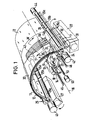
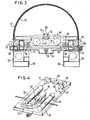
- the spatial arrangement of the embodiment according to FIGS. 3 and 4 is, however, made somewhat differently in order to achieve the desired scanning or exposure over a circumferential angle of 180 °.
- the circular segment-like holder 12 extends over a little more than 180 ° so that the web to be exposed can be scanned over the desired angle of 180 °.
- the circular segment-like holder thus has the shape of a half cylinder, which has the great advantage that the plane of the encoder cassette 27 runs parallel to the plane of the slave cassette and a simple symmetrical structure of the transport mechanism is given, the input side of the cassette 27 of the guide 58 and the Insertion roller pair 25 and on the output side of the removal roller pair 26, which consists of the guide device 59 extending through the cutting device 31 and the slave cassette 28.
- the axisymmetric design enables the encoder and slave cassette to be changed as required, which, when a later online development system is arranged, has a mechanically simplified effect.
- the semi-cylindrical arrangement is also characterized by the fact that it represents a very compact design in terms of height and depth.
- a special arrangement is made on the slide to enable scanning through 180 °.
- This arrangement can be seen in FIG. 4.
- the laser beam 18 ′ generated by the laser 18 first passes through a gray filter 57 and is then deflected by 90 ° by a deflection element 19. The beam then passes through a modulator 20 and hits a deflection element 21 again. After another deflection by 90 ° on the deflection element 21, the laser beam passes through a correction object tiv or a collimator 22 and then strikes a prism 23 '.
- This prism is tilted in its plane with respect to the slide, so that after two reflections on the inclined side surfaces of the prism, the laser beam strikes the rotating mirror arrangement 15 in a direction that coincides with the axis 16 of the circular segment-like holder 12.
- the rotating mirror arrangement has a rotating mirror 15 'with a flat mirror surface which forms an angle of 45 ° to the axis 16 of the segment-like holder 12.
- the tilted arrangement of the prism 23 ensures that the height of the laser beam 18' above the carriage 24 is increased, so that it is arranged in the direction of the axis of rotation 16 of the rotating mirror 15 'which is higher than the embodiment according to FIGS. 1 and 2. falls on it, the axis of rotation 16 being above the parts laterally adjacent on the slide, ie the laser 18 and the collimator 22.
- the device according to the invention both with individual sheets of the photosensitive sheet material and with webs thereof, e.g. Roll film can work.
Abstract
Eine optische Lichtfleck-Abtastvorrichtung bei Photosetzgeräten für ein photoempfindliches Bahnmaterial weist einen modulierten Laser (18), eine Abbildungsoptik und eine vom Laserstrahl beaufschlagte Drehspiegelanordnung (15) auf. Hierdurch wird der Laserstrahl (13) periodisch über die in ihrer Längsrichtung bewegte Bahn (11) geführt, wobei durch geeignete Modulation des Lasers (18) und linienweise Abtastung der Bahn (11) ein gewünschtes latentes Muster auf der Bahn erzeugt wird. Das Bahnmaterial ist in einer kreiszylindersegmentartig gekrümmten Form mit der photoempfindlichen Schicht auf der konkav gekrümmten Seite angeordnet. Die den Laserstrahl (13) zur photoempfindlichen Schicht lenkende Spiegelfläche (14) ist auf oder zumindestens nahe der Zylindersegmentachse (16) derart angebracht, dass der Laserstrahl (13) zwischen der Spiegefläche (14) und der photoempfindlichen Schicht während der gesamten Abtastbewegung im wesentlichen radial verläuft.An optical light spot scanning device in photosetting devices for a photosensitive web material has a modulated laser (18), an imaging optical system and a rotating mirror arrangement (15) acted upon by the laser beam. As a result, the laser beam (13) is guided periodically over the web (11) moved in its longitudinal direction, a desired latent pattern being generated on the web by suitable modulation of the laser (18) and line-by-line scanning of the web (11). The web material is arranged in a circular cylindrical segment-like shape with the photosensitive layer on the concave curved side. The mirror surface (14) directing the laser beam (13) to the photosensitive layer is attached on or at least close to the cylinder segment axis (16) such that the laser beam (13) between the mirror surface (14) and the photosensitive layer is essentially radial during the entire scanning movement runs.
Description
Die Erfindung betrifft eine optische Lichtfleck-Abtastvorrichtung bei Photosetzgeräten für ein photoempfindliches Blattmaterial mit einem modulierten Laser zur Erzeugung einesmodulierten Laserstrahles, mit einer kreiszylindersegmentartigen Halterung für das Blattmaterial,zur Halterung des Blattmaterials in einer teilzylindrischen Form mit einem parallel zur Achse der kreissegmentartigen Halterung verschiebbaren Schlitten, welche eine Abbildungsoptik und eine Drehspiegelanordnung trägt, deren Drehachse mit der Achse der kreiszylindersegmentartigen Halterung zusammenfällt, wobei der über die Abbildungsoptik auf die Drehspiegelanordnung fallende und nach erfolgter Reflexion an der Drehspiegelanordnung zum Blattmaterial radial gerichtete Laserstrahl durch die Drehung der Drehspiegelanordnung und Verschiebung des Schlittens das Blattmaterial zeilenweise abtastet und durch geeignete Modulation des Laserstrahles ein gewünschtes latentes Muster auf dem Material erzeugt. Eine Lichtfleck-Abtastvorrichtung dieser Art ist aus der DE-OS 31 26 642 bekannt und weist einige Vorteile gegenüber den bisher bei Photosetzgeräten eingesetzten Lichtfleck-Abtastvorrichtungen auf.The invention relates to an optical light spot scanning device in photosetters for a photosensitive sheet material with a modulated laser for generating a modulated laser beam, with a circular-cylindrical segment-like holder for the sheet material, for holding the sheet material in a partially cylindrical shape with a slide that can be moved parallel to the axis of the circular-segment-like holder, which carries an imaging optics and a rotating mirror arrangement, the axis of rotation of which coincides with the axis of the circular-segment-like holder, the laser beam falling via the imaging optics onto the rotating mirror arrangement and radially directed after reflection on the rotating mirror arrangement towards the sheet material by the rotation of the rotating mirror arrangement and displacement of the slide the sheet material scanned line by line and, by suitable modulation of the laser beam, generates a desired latent pattern on the material. A light spot scanning device of this type is known from DE-OS 31 26 642 and has some advantages over the light spot scanning devices previously used in photo setting devices.
Bei anderen bekannten optischen Lichtfleck-Abtastvorrichtungen (z.B. DE-OS 30 47 813) sind im allgemeinen aufwendige optische Korrektureinrichtungen erforderlich, um das in einer Ebene angeordnete photoempfindliche Bahnmaterial einwandfrei zu belichten. Das photoempfindliche Bahnmaterial wird bei diesen vorbekannten optischen Lichtfleck-Abtastvorrichtungen deshalb in ebener Anordnung belichtet, weil es von der Materialrolle zunächst in eine Aufnahmekassette überführt und erst dann belichtet wird. Der Laserstrahl tastet das in der Aufnahmekassette befindliche ebene Bahnmaterial Zeile für Zeile quer zu seiner Längsrichtung ab, was sowohl ein- als auch mehrzeilig in beiden Richtungen erfolgen kann. Es können aber auch gleichzeitig zeilenweise der Text in Spalten oder Kompositionen von oben nach unten belichtet und somit gesetzt werden.In other known optical light spot scanning devices (eg DE-OS 30 47 813), complex optical correction devices are generally required in order to properly expose the photosensitive web material arranged in one plane. The photosensitive web material in these previously known optical light spot scanning devices is exposed in a planar arrangement because it is first transferred from the roll of material into a recording cassette and only then exposed. The laser beam scans the flat web material located in the receiving cassette line by line transversely to its longitudinal direction, which can be done in both directions on one or more lines. However, the text in columns or compositions can also be exposed line by line from top to bottom and thus set.
Bei der DE-OS 31 26 642, welche zur Belichtung von Blattmaterial gedacht ist, wird durch die zylindrische Form des gehaltenen Blattes und die Anordnung des Drehspiegels an der Zylinderachse der Halterung die optische Geometrie weitgehend vereinfacht bzw. die Winkelgeschwindigkeit der Abtastung gleichmäßig gehalten, so daß aufwendige optische Korrektureinrichtungen entfallen.In DE-OS 31 26 642, which is intended for the exposure of sheet material, the optical geometry is largely simplified or the angular velocity of the scanning is kept uniform by the cylindrical shape of the sheet held and the arrangement of the rotating mirror on the cylinder axis of the holder that elaborate optical correction devices are eliminated.
Trotz dieser Verbesserung müssen bei der eingangs genannten Lichtfleck-Abtastvorrichtung besondere Maßnahmen getroffen werden, um ein latentes Muster mit optimaler Schärfe zu erhalten. Auch lässt die bekanntsAnordnung eine Belichtung des Blattmaterials über einen Umfangswinkel von etwa 180° nicht zu.Despite this improvement, special measures must be taken in the light spot scanning device mentioned at the outset in order to obtain a latent pattern with optimum sharpness. The known arrangement also does not allow exposure of the sheet material over a circumferential angle of approximately 180 °.
Aufgabe der vorliegenden Erfindung ist es die eingangs genannte Vorrichtung so weiterzubilden, daß auf einfache und unaufwendige Weise eine scharfe einwandfreie und exakte Qualitätsabbildung des Laserlichtflecks auf dem photoempfindlichen Material und gleichzeitig ein kompakter Aufbau gewährleistet wird und zwar auch bei Photosetzgeräten, die mit photoempfindlichem Material in Bahnform arbeiten, wobei ggf. eine Belichtung des Blattmaterials über einen Umfangswinkel von etwa 180° möglich sein sollte.The object of the present invention is to develop the device mentioned at the outset in such a way that a simple and uncomplicated way ensures a sharp, flawless and exact image of the quality of the laser light spot on the photosensitive material and, at the same time, a compact structure, even in the case of photosetters which are in the form of a web with photosensitive material work, whereby exposure of the sheet material over a circumferential angle of about 180 ° should be possible.
Zur Lösung dieser Aufgabe wird erfindungsgemäß vorgeschlagen, daß auch der Laser auf dem Schlitten angeordnet ist und vorzugsweise, daß der Laser, die Abbildungsoptik sowie etwaige vorhandene den Laserstrahl umlenkende Teile in einer flachen Anordnung auf dem Schlitten angebracht sind, der im wesentlichen parallel zu einer die beiden Enden der kreiszylindersegmentartigen Halterung enthaltenden Ebene verläuft.To solve this problem, the invention proposes that the laser is arranged on the carriage and preferably that the laser, the imaging optics and any existing parts deflecting the laser beam are mounted in a flat arrangement on the carriage, which is substantially parallel to one of the both ends of the plane containing the circular cylinder segment-like plane.
Dadurch, daß der Laser sich auf dem Schlitten befindet, bleibt die gesamte optische Geometrie während des Abtastens fest, so daß Unschärfe aufgrund sich ändernder optischer Geometrie gar nicht eintreten kann. Auch führtein allmähliches Divergieren des Laserstrahls mit zunehmendem Abstand vom Laser zu keinem Herabsetzen der Abbildungsqualität, da mit der erfindungsgemäßen Anordnung der optische Abstand zwischen dem Laser und dem zu belichtenden Material konstant bleibt, und eventuell vorhandene Divergenz mittels einem einfachen Korrekturobjektiv korrigiert werden kann. Weiterhin können unterschiedliche Schwingungen des Lasers gegenüber dem Schlitten nicht mehr auftreten, da der Laser mit dem Schlitten verbunden ist, so daß auf diesen Ursprung zurückzuführende Unschärfe nicht vorkommt. Durch die bevorzugte Anordnung des Lasers, der Abbildungsoptik sowie etwaigen vorhandenen den Laserstrahl umlenkenden Teile in einer flachen Anordnung auf dem Schlitten der im wesentlichen parallel zu einer die beiden Enden der kreiszylindersegmentartigen Halterung erhaltenden Ebene verläuft, wird die Vorrichtung kompakter und zwar nicht nur weil der Laser nicht mehr entfernt vom Schlitten liegt sondern weil der Schlitten und die daraufmontierten Teile in einer flachen Konstruktion am Boden der Halterung platzsparend untergebracht werden können.Because the laser is on the carriage, the entire optical geometry remains fixed during the scanning, so that blurring cannot occur due to changing optical geometry. Also gradually led Lich diverging of the laser beam with increasing distance from the laser to no reduction in imaging quality, since with the arrangement according to the invention the optical distance between the laser and the material to be exposed remains constant, and any divergence that may be present can be corrected by means of a simple correction lens. Furthermore, different vibrations of the laser with respect to the carriage can no longer occur, since the laser is connected to the carriage, so that blurring due to this origin does not occur. Due to the preferred arrangement of the laser, the imaging optics and any existing parts deflecting the laser beam in a flat arrangement on the slide which runs essentially parallel to a plane that maintains the two ends of the circular segment-like holder, the device becomes more compact, and not just because of the laser no longer lies away from the sled, but because the sled and the parts mounted on it can be housed in a flat construction on the bottom of the holder to save space.
Der Laserstrahl kann also exakt auf die photoempfindliche Schicht fokussiert werden.The laser beam can therefore be focused precisely on the photosensitive layer.
Eine besonders günstige Anordnung der einzelnen Elemente auf dem Schlitten ist dadurch gekennzeichnet, daß der Laser neben der Drehspiegelanordnung und im wesentlichen parallel zu seiner Drehachse, anschließend ein 90°-Umlenkspiegel, dann ein Lasermodulator, ein weiterer 90°-Umlenkspiegel, gegebenenfalls ein Korrekturobjektiv und schließlich auf der vom Laser abgewandten Seite der Drehspiegelanordnung ein Umlenkelement, der den Laserstrahl zur Drehspiegelanordnung lenkt, auf dem Schlitten angeordnet sind.A particularly favorable arrangement of the individual elements on the slide is characterized in that the laser next to the rotating mirror arrangement and essentially parallel to its axis of rotation, then a 90 ° deflecting mirror, then a laser modulator, another 90 ° deflecting mirror, possibly a correction lens and Finally, on the side of the rotating mirror arrangement facing away from the laser, a deflection element, which directs the laser beam to the rotating mirror arrangement, is arranged on the carriage.
Hierdurch wird bei einer flachen Anordnung der zur Verfügung stehende Raum unterhalb der Halterung optimal genutzt. Bevorzugt trifft der Laserstrahl auf die Drehspiegelanordnung in einer Richtung, die mit der Achse der kreissegmentartigen Halterung zusammenfällt. Bei dieser Ausführungsform weist die Drehspiegelanordnung bevorzugt einen Drehspiegel auf, mit einer zur Achse der kreissegmentartigen Halterung einen Winkel von 45° einschließenden ebenen Spiegelfläche.As a result, the space available below the holder is optimally used in a flat arrangement. The laser beam preferably strikes the rotating mirror arrangement in a direction that coincides with the axis of the circular segment-like holder. In this embodiment, the rotating mirror arrangement preferably has a rotating mirror, with a flat mirror surface enclosing an angle of 45 ° to the axis of the circular segment-like holder.
Auf diese Weise gelingt es, sofern die Drehachse der Drehspiegelanordnung oberhalb der auf dem Schlitten seitlich benachbarten Teile liegt, eine wirksame Abtastung bzw. Belichtung des Blattmaterials über einen Umfangswinkel von 180 0 oder sogar noch mehr zu erreichen.In this way, it is possible provided that the rotational axis of the rotary mirror arrangement lies above the laterally adjacent parts on the carriage to achieve an effective sampling or exposure of the sheet material over a circumferential angle of 18 0 0 or even more.
Diese Anordnung des Drehspiegels läßt sich dadurch erreichen, daß entweder freie Räume links und rechts vom Drehspiegel vorhanden sind oder aber, daß der Laserstrahl vor dem Auftreffen auf dem Drehspiegel erst nach oben versetzt wird. Dies kann dadurch geschehen, daß der Laserstrahl auf den Drehspiegel durch ein in seiner Ebene gegenüber dem Schlitten gekippt angeordnetes Prisma gelenkt wird, welches eine etwa 180°-Umlenkung des Laserstrahls bewirkt.This arrangement of the rotating mirror can be achieved in that either there are free spaces to the left and right of the rotating mirror or that the laser beam is first displaced upwards before hitting the rotating mirror. This can be done in that the laser beam is directed onto the rotating mirror by a prism which is tilted in its plane with respect to the slide and which causes an approximately 180 ° deflection of the laser beam.
Bei einer bevorzugten praktischen Ausführung wird vorgesehen, daß das Material in Form einer Bahn vorliegt, die aus einer an dem einen Ende der als Kreiszylindersegment ausgebildeten Halterung angeordneten Geberkassette kommt, an dem Kreizylindersegment entlanggeführt und von einer an dem anderen Ende der Halterung von einer Nehmerkassette aufgenommen wird. Auf diese Weise können die Geber- und Nehmer kassetten platzsparend untergebracht werden, ohne die gesamten Abmessungen der Vorrichtung wesentlich zu vergrößern.In a preferred practical embodiment it is provided that the material is in the form of a web which comes from a donor cassette arranged at one end of the holder designed as a circular cylinder segment, is guided along the circular cylinder segment and is received by a slave cassette at the other end of the holder becomes. In this way, the donor and slave cassettes can be accommodated in a space-saving manner without significantly increasing the overall dimensions of the device.
Vorteilhafterweise ist das Kreiszylindersegment durchsichtig und das Bahnmaterial außen um das Zylindersegment herumgelegt. Das Kreiszylindersegment gibt somit die Form des flexiblen Bahnmaterials vor. Um eine problemlose Abtastung mit einer Drehspiegelanordnung zu erzielen, soll dabei vorgesehen sein, daß das Kreiszylindersegment sich über einen Winkel von 100 bis 180° und insbesondere über 180° erstreckt. Im allgemeinen besteht das Kreiszylindersegment aus einem Glaszylinderausschnitt, der sich in Umfangsrichtung um etwa 180° erstreckt.The circular cylinder segment is advantageously transparent and the web material is laid around the outside of the cylinder segment. The circular cylinder segment thus specifies the shape of the flexible web material. In order to achieve a smooth scanning with a rotating mirror arrangement to be provided in that the circular cylinder segment extends over an angle 100 to 18 0 ° and in particular about 180 °. In general, the circular cylinder segment consists of a glass cylinder cut-out which extends in the circumferential direction by approximately 180 °.
Besonders vorteilhaft ist es, wenn die Längsachse des Bahnmaterials kreisförmig entlang des Kreiszylindersegments verläuft. Mit anderen Worten soll das Bahnmaterial in seiner Längsrichtung um das Kreiszylindersegment herumgeführt werden, so daß die Längsachse und dazu parallel verlaufende Längslinien zu peripheren bzw. Umfangslinien des Kreiszylindersegments parallel verlaufen. Senkrecht auf der Längsachse stehende und in der Bahnmaterialfläche liegende Linien verlaufen demgegenüber parallel zu den Erzeugenden des Kreiszylindersegments bzw. zur Zylindersegmentachse.It is particularly advantageous if the longitudinal axis of the web material runs in a circle along the circular cylinder segment. In other words, the web material is to be guided in its longitudinal direction around the circular cylinder segment, so that the longitudinal axis and longitudinal lines parallel to it run parallel to peripheral or circumferential lines of the circular cylinder segment. In contrast, lines perpendicular to the longitudinal axis and lying in the web material surface run parallel to the generatrices of the circular cylinder segment or to the cylinder segment axis.
Im Gegensatz zu der vorbekannten Anordnung (DE-OS 30 47 813) werden bei dem erfindungsgemäßen System also Texte und Bilder nicht mehr quer zur Längsrichtung des photoempfindlichen Bahnmaterials, sondern vielmehr in dessen Längsrichtung, d.h. von oben nach unten und nicht mehr horizontal vom Laserstrahl abgetastet. Durch diese Anordnung wird gewährleistet, daß das photoempfindliche Bahnmaterial in seiner natürlichen Biegerichtung abgebogen wird, die es bereits auf der Vorratsspule aufwies und auf der Aufnahmespule wieder einnehmen wird.In contrast to the previously known arrangement (DE-OS 30 47 813), in the system according to the invention, texts and images are no longer transversely to the longitudinal direction of the photosensitive web material, but rather in the longitudinal direction thereof, i.e. from top to bottom and no longer scanned horizontally by the laser beam. This arrangement ensures that the photosensitive web material is bent in its natural bending direction, which it already had on the supply reel and will take up again on the take-up reel.
Zwecks einwandfreiem Transports des photoempfindlichen Bahnmaterials über das Kreiszylindersegment' sollen an den Umfangsenden des Kreiszylindersegments parallel zur Zylindersegmentachse verlaufende Bahnmaterial-Einführung- bzw. Abführungswalzenpaare vorgesehen sein.For the purpose of proper transport of the photosensitive web material over the circular cylinder segment, pairs of web material introduction and discharge rollers running parallel to the cylinder segment axis should be provided on the circumferential ends of the circular cylinder segment.
Zumindest sollen hierbei die Abführungswalzenpaare motorisch angetrieben sein. Vorzugsweise sind aber auch die Einführungswalzenpaare motorisch angetrieben.At least the pairs of discharge rollers should be motor-driven. However, the pairs of insertion rollers are preferably also driven by a motor.
Die erfindungsgemäße Ausbildung ermöglicht es, daß die Einführungswalzenpaare und die Abführungswalzenpaare in ihrer Längsrichtung in mehrere unterschiedlich antreibbare bzw. leerlaufende Abschnitte unterteilt sind. Hierbei wird eine besonders vorteilhafte Eigenschaft der erfindungsgemäßen Vorrichtung ausgenutzt, welche darin besteht, daß die Formatbreite keine Rolle spielt. Somit ist bei auf das breitestmögliche Format erfolgter Auslegung der Vorrichtung die Möglichkeit gegeben, zwei verschiedene photoempfindliche Bahnmaterialien in gleicher oder unterschiedlicher Materialbreite durch die Vorrichtung hindurchzuführen. Dies ist z.B. für den Fall sehr wichtig, daß die Korrektur auf Papier und die Endbelichtung auf Film zur übertragung auf eine Offset-Platte erfolgt. Die Walzenpaare haben dann z.B. einen gemeinsamen Kern von 500 mm Breite, wobei ein Abschnitt 250 mm breit ist und durch einen-Motor angetrieben wird. In der Mittelzone befindet sich dann ein lose mitlaufendes Stück von 70 mm Breite. Am Ende wiederum befindet sich ein angetriebenes Stück von 180 mm Breite. Auf diese Weise kann durch den synchronen Antrieb aller Motoren ein Bahnmaterial der maximalen Breite von 500 mm transportiert werden. Es können aber auch nebeneinander zwei Materialbahnen von je 205 mm Breite (Standard) belichtet werden. Weiter ist es möglich, ein Bahnmaterial von 300 mm Breite neben einem Schmalformat von 70 mm Breite zu belichten.The design according to the invention makes it possible for the insertion roller pairs and the removal roller pairs to be divided in their longitudinal direction into a plurality of differently drivable or idling sections. Here, a particularly advantageous property of the device according to the invention is used, which consists in the fact that the format width does not matter. Thus, when the device is designed for the widest possible format, it is possible to feed two different photosensitive web materials through the device in the same or different material width. This is very important, for example, in the event that the correction on paper and the final exposure on film for transmission on an offset plate. The roller pairs then have, for example, a common core of 500 mm width, a section being 250 mm wide and being driven by a motor. In the middle zone there is a loose piece with a width of 70 mm. At the end there is a driven piece 180 mm wide. In this way, a sheet material with a maximum width of 500 mm can be transported through the synchronous drive of all motors. However, two material webs each 205 mm wide (standard) can also be exposed side by side. It is also possible to expose a sheet material of 300 mm width in addition to a narrow format of 70 mm width.
Zweckmäßigerweise ist vor bzw. nach dem Einführungswalzenpaar bzw. dem Abführungswalzenpaar wenigstens eine Geber- bzw. Nehmerkassette angeordnet.At least one donor or slave cassette is expediently arranged in front of or after the pair of introduction rollers or the pair of discharge rollers.
Dabei soll die Anordnung so sein, daß die Breite der Kassetten gleich der Breite eines Abschnittes oder mehrerer nebeneinanderliegender Abschnitte ist.The arrangement should be such that the width of the cassettes is equal to the width of a section or a number of adjacent sections.
Um auch mit unterschiedlich großen Kassetten arbeiten zu können, ist eine weitere Ausführungsform so ausgebildet, daß zur Aufnahme von Geberkassetten bzw. Nehmerkassetten unterschiedlicher Größe jeweils ein auf kleinere Kassettengrößen reduzierbarer Kassettenaufnahmeraum vorgesehen ist, welcher für die Aufnahme der größtmöglichen Kassettengröße ausgelegt ist.In order to be able to work with cassettes of different sizes, a further embodiment is designed in such a way that a cassette receiving space which can be reduced to smaller cassette sizes and which is designed to accommodate the largest possible cassette size is provided for accommodating donor cassettes or slave cassettes of different sizes.
Um schließlich das in die Nehmerkassette überführte photoempfindliche Bahnmaterial vom noch auf dem Zylindersegment befindlichen Bahnmaterial trennen zu können, ist zweckmäßig zwischen die Abführungswalzenpaare und die Nehmerkassette bzw. die Nehmerkassetten eine Schneidvorrichtung eingeschaltet.In order to finally be able to separate the photosensitive web material transferred into the slave cassette from the web material still on the cylinder segment, a cutting device is expediently connected between the removal roller pairs and the slave cassette or the slave cassettes.
Um das photoempfindliche Bahnmaterial nach außen lichtdicht und gegen Beschädigung abzudecken, ist weiter vorzugsweise vorgesehen, daß außen um das Kreiszylindersegment mit Abstand von diesem eine lichtundurchlässige Führungsabdeckung herumgelegt ist.In order to cover the photosensitive web material so that it is light-tight to the outside and against damage, it is further preferably provided that an opaque guide cover is placed around the outside of the circular cylinder segment at a distance from it.
Um jedoch das um das Zylindersegment herumgelegte Bahnmaterial z.B. im Falle von Störungen zugänglich zu machen, sieht eine weitere Ausführungsform vor, daß die Führungsabdeckung um eine parallel zur Zylindersegmentachse verlaufende Schwenkachse nach oben wegschwenkbar angebracht ist.However, around the web material wrapped around the cylinder segment e.g. To make accessible in the event of malfunctions, a further embodiment provides that the guide cover is attached so that it can be pivoted upward about a pivot axis running parallel to the cylinder segment axis.
Die Erfindung wird im folgenden beispielsweise anhand der Zeichnung beschrieben; in dieser zeigt:
- Fig. 1 eine schematische, zum Teil aufgebrochene perspektivische Ansicht einer optischen Lichtfleck-Abtastvorrichtung für ein photoempfindliches Bahnmaterial bei optischen Photosetzgeräten und
- Fig. 2 einen Axialschnitt der optischen Lichtfleck-Abtastvorrichtung nach Fig. 1, in dem jedoch mehr Einzelheiten gezeigt sind.
- Fig. 3 eine Stirnansicht einer weiteren bevorzugten Ausführungsform, die die Belichtung des photoempfindlichen Blattmaterials über einen Umfangswinkel von 180° ermöglicht,
- Fig. 4 eine perspektivische Ansicht des Schlittens der Ausführungsform gemäß Fig. 3.
- Fig. 1 is a schematic, partially broken perspective view of an optical light spot scanner for a photosensitive web material in optical photosetters and
- Fig. 2 is an axial section of the optical light spot scanner according to Fig. 1, but in which more details are shown.
- 3 shows an end view of a further preferred embodiment, which enables the exposure of the photosensitive sheet material over a circumferential angle of 180 °,
- 4 shows a perspective view of the carriage of the embodiment according to FIG. 3.
Nach Fig. 1 und 2 erstreckt sich ein aus Glas bestehendes Kreiszylindersegment 12 um seine Zylindersegmentachse 16 oberhalb derselben über einen Winkel von 120°. An den Umfangsenden ist das Kreiszylindersegment 12 in Kunststoffleisten 34 (Fig. 2) gelagert, welche ihrerseits über sich im wesentlichen radial erstreckende Blechstützen 35 am Gestell 36 der Vorrichtung befestigt sind. !1 and 2, a
Mit geringfügigem Abstand ist das Kreiszylindersegment von; einer ebenfalls kreiszylindersegmentförmigen Führungsabdeckung 32 umgeben, welche nach Fig. 2 im Bereich des linken Umfangsendes des Kreiszylindersegmentes 12 um eine parallel zur Zylindersegmentachse 16 verlaufende Schwenkachse 33 schwenkbar gelagert ist, so daß die Führungsabdeckung 32 in Richtung des Pfeiles f in Fig. 2 nach oben aufgeklappt werden kann, sofern zuvor der Deckel 37 der Vorrichtung abgenommen bzw. aufgeklappt wurde.At a short distance the circular cylinder segment is from; a likewise circular cylindrical segment-
An der Vorderseite der Vorrichtung befindet sich nach Fig. 2 ein Bedienungspult 38.2, there is a
Im hinteren Bereich der Vorrichtung ist unmittelbar vor dem Kreiszylindersegment 12 ein Einführungswalzenpaar 25 vorgesehen, dessen Achsen sich parallel zur Zylindersegmentachse 16 erstrecken. In entsprechender Weise ist am entgegengesetzten Umfangsende des Kreiszylindersegments 12 im vorderen Bereich der Vorrichtung ein Abführungswalzenpaar 26 untergebracht.In the rear area of the device, an
Vor bzw. hinter dem Einführungswalzenpaar 25 bzw. dem Abführungswalzenpaar 26 sind Kassettenaufnahmeräume 29, 30 vorgesehen, in denen Geberkassetten 27 bzw. Nehmerkassetten 28 unterschiedlicher Größe untergebracht werden können.In front of or behind the pair of
Nach Fig. 2 sind in den Kassettenaufnahmeräumen 29, 30, die für Kassetten mit einem Querschnitt von 140 mm2 ausgelegt sind, vermittels eines Adapterstückes 39 bzw. 40 kleinere Kassetten 27, 28 mit einem Querschnitt von 100 mm2 angeordnet.2, in the
Trotz der relativ großen Kassettenaufnahmeräume 29 bzw. 30 hat die Gesamtvorrichtung nur eine Tiefe von etwa 75 cm bei einer Höhe von knapp 50 cm. Die Breite (Fig. 1) liegt bei etwa 70 cm. Hierbei ist eine großformatige Belichtungsfläche von 500 x 600 mm zugrundegelegt. Dabei beträgt der Umfang des Kreiszylindersegments 12 600 mm, während die axiale Erstreckung des Kreiszylindersegments 12 500 mm ausmacht.Despite the relatively large
Von der Geberkassette 27 wird photoempfindliches Bahnmaterial 11 abgerollt und um das Kreiszylindersegment 12 herumgelegt. Hierbei wird das Bahnmaterial 11 durch das Einführungswalzenpaar 25 und das Abführungswalzenpaar 26 hindurchgeführt. Es gelangt dann schließlich in die Nehmerkassette 28, wo es erneut aufgerollt wird.Photosensitive web material 11 is unwound from the
Nach den Fig. 1 und 2 befindet sich zwischen den Abführungswalzenpaaren 26 und der Nehmerkassette 28 eine Schneidvorrichtung 31, die aus einem Messer besteht, welches in Querrichtung der Bahn in Richtung des Pfeiles F (Fig. 1) bewegbar ist, um das bereits in der Nehmerkassette 28 befindliche photoempfindliche Bahnmaterial von dem noch auf dem Zylindersegment 12 aufliegenden Bahnmaterial zu trennen.According to FIGS. 1 and 2, between the removal roller pairs 26 and the
Nach Fig. 1 weisen das Einführungswalzenpaar 25 und das Abführungswalzenpaar 26 jeweils drei Abschnitte 25a, 25b, 25c bzw. 26a, 26b, 26c auf. Die in Fig. 1 linken Walzenpaare 25a, 26a sind jeweils durch Motore 41, 42 angetrieben. Der Antrieb wirkt jeweils nur auf eine, und zwar die innere Walze des Walzenpaares.According to FIG. 1, the pair of
Die Walzenpaare 25a, 26a haben zweckmäßig eine Länge von 250 mm. Anschließend folgt dann ein kurzer Walzenpaarabschnitt 25b, 26b mit einer Länge von etwa 70 mm. Dieser Walzenpaarabschnitt ist nicht angetrieben, sondern läuft frei mit. Am Ende befinden sich dann wieder Walzenpaarabschnitte 25c, 26c, die durch Motore 43 bzw. 44 angetrieben sind. Auch in diesem Fall wird lediglich der innere Walzenabschnitt von einem der Motore 43, 44 angetrieben.The roller pairs 25a, 26a expediently have a length of 250 mm. This is followed by a short
In der Zeichnung ist gezeigt, wie ein photoempfindliches Bahnmaterial von 205 mm Breite durch die ersten Walzenpaarabschnitte 25a bzw. 26a um die linke Hälfte des Kreiszylindersegments 12 herumgeführt sind. Die Führungsabdeckung 32 ist teilweise weggebrochen, um das Bahnmaterial 11 zu veranschaulichen.The drawing shows how a photosensitive web material with a width of 205 mm is guided through the first
Im Innern des Zylindersegments 12 befindet sich ein Schlitten 24, der auf zwei Führungsstangen 45, 46, die parallel zur Zylindersegmentachse 16 verlaufen, axial geführt ist, und zwar mittels Kugelbuchsen 47, 48 (Fig. 2). An dem Schlitten ist über einen Arm 49 ein Phototransistor 50 befestigt, welcher mit nicht dargestellten Marken am vorderen Umfangsrand des Kreiszylindersegments 12 zusammenarbeitet, um die Bewegung des Schlittens 24 in Axialrichtung mit der noch zu beschreibenden Abtastbewegung des Laserstrahls 13 zu synchronisieren.In the interior of the
Der Schlitten wird in Axialrichtung 16 durch eine Spindel 51 angetrieben, die in einer am Schlitten 24 befestigten Mutter 52 (Fig. 2) drehbar angeordnet ist. Ein Motor 53 (Fig. 1) treibt die Spindel 51 in gesteuerter Weise zu einer Drehbewegung an.The carriage is driven in the
Auf dem Schlitten 24 ist nach den Fig. 1 und 2 parallel zur Zylindersegmentachse 16 ein Laser 18 angeordnet, der einen Lichtstrahl parallel zur Zylindersegmentachse 16 zu einem - 90°-Umlenkspiegel 19 lenkt, der den Laserstrahl nach innen zu einem Lasermodulator 20 lenkt. Der im Sinne des zu erzeugenden Schriftbildes modulierte Laserstrahl gelangt dann auf einen weiteren 90°-Umlenkspiegel 21, welcher dem Strahl eine erneute 90°-Umlenkung erteilt, so daß er wieder parallel aber entgegengesetzt zu dem aus dem Laser 18 austretenden Strahl verläuft. Der Strahl gelangt dann durch ein Korrekturobjektiv 22 auf einen dritten 90°-Umlenkspiegel 23, welcher den Laserstrahl wieder in Richtung des Lasers 18 umlenkt. Zwischen dem Laser 18 und dem Umlenkspiegel 23 befindet sich ein Drehspiegel 15, dessen Drehachse 54 mit der Zylindersegmentachse 16 zusammenfällt und in der Spiegelfläche 14 liegt. Ein Motor 55 treibt den Drehspiegel 15 zu einer kontinuierlichen Drehbewegung an. Auf diese Weise wird ein radial verlaufender Laserstrahl 13 auf die nach innen gerichtete photoempfindliche Schicht des photoempfindlichen Bahnmaterials 11 gerichtet.1 and 2, a
In Fig. 2 sind die beiden durch einen Winkel von 60° getrennten Stellungen des Drehspiegels 15 . eingezeichnet, welche den beiden extremen Winkelpositionen des radialen Laserstrahls 13 entsprechen. Durch kontinuierliche Drehung des Drehspiegels 15 wird also das photoempfindliche Bahnmaterial 11 zwischen den beiden in Fig. 2 dargestellten Extremlagen kontinuierlich vom Laserstrahl 13 abgetastet. Indem der Schlitten 24 nach jeder Winkelabtastung mittels des Drehspiegels 15 um ein kleines Stück vorgeschoben wird, kann so die gesamte Breite des Bahnmaterials 11 spaltenweise vom Laserstrahl 13 abgetastet werden. Durch geeignete Modulation wird dann auf dem photoempfindlichen Bahnmaterial ein latentes Bild erzeugt, wie es bei 56 in Fig. 1 schematisch angedeutet ist.2, the two positions of the
Wesentlich ist, daß die Mittellängsachse 17 des Bahnmaterials kreisförmig um das Kreiszylindersegment 12 herumgelegt ist, so daß das Photomaterial in seiner natürlichen Biegungsrichtung angeordnet und in dieser Position fehlerfrei belichtet wird.It is essential that the central longitudinal axis 17 of the web material is placed in a circle around the
Aus Fig. 2 ergibt sich, daß einem Schwenkwinkel des Drehspiegels 15 um 600 eine Ablenkung des-Laserstrahls 13 um 120° entspricht. Sowohl der Laserstrahl 13 als auch der Drehspiegel bewegen sich nach Fig. 1 und 2 entgegen dem Uhrzeigersinn in Richtung der Pfeile P. Das Bahnmaterial wird dagegen nach Fig. 1 in Richtung des Pfeiles W bewegt.From Fig. 2 it follows that a pivoting angle of the
Vor der Belichtung wird das Bahnmaterial von der Geberkassette 27 abgezogen und um das Kreiszylindersegment 12 herumgelegt. Anschließend befindet sich dann das photoempfindliche Bahnmaterial 11 zur Durchführung der Belichtung in Ruhe.Before the exposure, the web material is pulled off the
Mit der die Ablenkung des Laserstrahls 13 und den Vorschub des Schlittens 24 steuernden Elektronik ist es aufgrund einer geeigneten Speicherorganisation möglich, die zu belichtenden Text- und Bildteile so vorzusortieren, daß unter Verwendung einer geeigneten Programmierung die Bilder nicht nur in der aus der Zeichnung ersichtlichen Form in der Vorschubrichtung des photoempfindlichen Bahnmaterials belichtet werden, sondern auch in einer Richtung 90° zur Abtastrichtung des Laserstrahls, d.h. in Axialrichtung.With the electronics controlling the deflection of the
Der Schlitten 24 beginnt bei eingelaufenem und um das Kreiszylindersegment 12 herumgelegtem photoempfindlichen Bahnmaterial mit dem kontinuierlichen Belichten vorne rechts in der Ecke bei der Darstellung der Fig. 1. Der Abtastlaserstrahl 13 wird durch den mit dem Schlitten 24 verbundenen Phototransistor 50 synchronisiert. Der Schlitten bewegt sich kontunierlich oder schrittweise während des Belichtungsvorgangs nach den Fig. 1 und 2 von vorn nach hinten. Der Antrieb des Schlittens 24 kann auch durch ein Stahlband erfolgen. Die Verwendung eines Monospiegels 15 hat gegenüber Polygonprismen bzw. Spiegelrädern den Vorteil, daß der Strahl ohne Auswandern der Trommelachse exakt projiziert werden kann. Da das erfindungsgemäße System technisch so konzipiert ist, daß die Formatbreite keine Rolle spielt, ist die Vorrichtung bevorzugt auf das größte zu verarbeitende Nutzformat von 500 x 600 mm ausgelegt. Um die besonders breite Materialführung sinnvoll zu nutzen, ist erstmalig bei dem erfindungsgemäßen System die Möglichkeit gegeben, zwei verschiedene Materialien in gleicher oder unterschiedlicher Materialbreite im System zu führen. Dies ist sehr wichtig, wenn die Korrektur auf Papier und die Endbelichtung auf Film zur Übertragung auf eine Offset-Platte erfolgt.With the photosensitive web material running in and wrapped around the
Die Walzen der Walzenpaare 25 bzw. 26 haben einen gemeinsamen Kern von 500 mm Breite, auf dem die erwähnten Walzenpaarabschnitte 25a, 25b, 25c bzw. 26a, 26b bzw. 26c angeordnet sind.The rollers of the roller pairs 25 and 26 have a common core of 500 mm width, on which the
Die Achsen der Bahnmaterialrollen in den Kassetten 27, 28, der Walzenpaare 25, 26 und die Zylindersegmentachse verlaufen also erfindungsgemäß alle parallel zueinander ebenso wie die Bewegungsrichtung des Schlittens 24.The axes of the web material rolls in the
Ein wesentlicher Vorteil der erfindungsgemäßen Anordnung besteht darin, daß auf stehendem Photomaterial belichtet werden kann.An essential advantage of the arrangement according to the invention is that exposure can be carried out on standing photo material.
Durch die große Ablenkung von 60° bei dieser optischen Einrichtung wird 1/6 der Gesamtumdrehung des Drehspiegels 15 für die Lichtfleckprojektion genutzt, und es kann vorteilhafterweise auf die Anordnung eines Polygon-Spiegels verzichtet werden.Due to the large deflection of 60 ° in this optical device, 1/6 of the total rotation of the
Eine noch größere Ablenkung ist bei der Ausführungsform gemäß Fig. 3 und 4 möglich. Bei dieser Ausführung bedeuten die gleichen Bezugszeichen auch die gleichen Teile bei der Ausführung gemäß Fig. 1 und 2.An even greater distraction is possible in the embodiment according to FIGS. 3 and 4. In this embodiment, the same reference numerals also mean the same parts in the embodiment according to FIGS. 1 and 2.
Die räumliche Anordnung der Ausführung gemäß Fig. 3 und 4 ist jedoch etwas anders getroffen, um die erwünschte Abtastung bzw. Belichtung über einen Umfangswinkel von 180° zu erreichen. Zunächst erstreckt sich die kreissegmentartige Halterung 12 über etwas mehr als 180°, damit die zu belichtende Bahn über den erwünschten Winkel von 180° abgetastet werden kann. Die kreissegmentartige Halterung hat somit die Form eines Halbzylinders, was den großen Vorteil bietet, daß die Ebene der Geberkassette 27 mit der Ebene der Nehmerkassette parallel läuft und ein einfacher symmetrischer Aufbau der Transportmechanik gegeben ist, die eingangsseitig aus der Kassette 27 der Führung 58 und dem Einführungswalzenpaar 25 und ausgangsseitig aus dem Abführungswalzenpaar 26, der sich durch die Schneidvorrichtung 31 erstreckenden Führung 59 und der Nehmerkassette 28 besteht. Der achssymmetrische Aufbau ermöglicht den beliebigen Wechsel von Geber-und Nehmerkassette, was bei Anordnung eines späteren Online-Entwicklungssystems mechanisch vereinfachend wirkt. Die halbzylindrische Anordnung zeichnet sich darüberhinaus dadurch aus, daß sie eine sehr kompakte Bauform in der Höhe und Tiefe darstellt.The spatial arrangement of the embodiment according to FIGS. 3 and 4 is, however, made somewhat differently in order to achieve the desired scanning or exposure over a circumferential angle of 180 °. First, the circular segment-
Um die Abtastung durch 180° zu ermöglichen, wird eine besondere Anordnung auf dem Schlitten getroffen. Diese Anordnung läßt sich der Fig. 4 entnehmen. Wie ersichtlich, läuft der vom Laser 18 erzeugte Laserstrahl 18' zunächst durch einen Graufilter 57 und er wird dann durch ein Umlenkelement 19 um 90° umgelenkt. Der Strahl läuft dann durch einen Modulator 20 und trifft wieder auf ein Umlenkelement 21 auf. Nach erneuter Umlenkung um 90° am Umlenkelement 21 läuft der Laserstrahl durch ein Korrekturobjektiv bzw. einem Kollimator 22 und fällt dann auf ein Prisma 23' auf. Dieses Prisma ist in seiner Ebene gegenüber dem Schlitten gekippt angeordnet, so daß der Laserstrahl nach zwei Reflexionen an den zueinander geneigten Seitenflächen des Prismas auf die Drehspiegelanordnung 15 in einer Richtung auftrifft, die mit der Achse 16 der kreissegmentartigen Halterung 12 zusammenfällt. Die Drehspiegelanordnung weist einen Drehspiegel 15' mit einer zur Achse 16 der kreissegmentartigen Halterung 12 einen Winkel von 45° einschließenden ebenen Spiegelfläche auf.A special arrangement is made on the slide to enable scanning through 180 °. This arrangement can be seen in FIG. 4. As can be seen, the
Durch die gekippte Anordnung des Prismas 23' wird sichergestellt, daß die Höhe des Laserstrahls 18' oberhalb des Schlittens 24 vergrößert wird, so daß er in Richtung der im Vergleich zu der Ausführungsform gemäß Fig. 1 und 2 höher angeordneten Drehachse 16 des Drehspiegels 15' auf diesen fällt, wobei die Drehachse 16 oberhalb der auf dem Schlitten seitlich benachbarten Teile, d.h. des Lasers 18 und des Kollimators 22 liegt. Somit bewirkt eine Drehung des Drehspiegels 15' durch 1800 um seine Drehachse eine Abtastung bzw. Belichtung der Bahn um eine Umfangswinkel von 180°.The tilted arrangement of the prism 23 'ensures that the height of the laser beam 18' above the
Aus der Zeichnung gemäß Fig. 3 entnimmt man, daß die zwei Führungsstangen 45, 46 für den Schlitten 24 etwa in der Höhe der Längsseiten der Schlitten angebracht sind. Eine leichte Gleitbewegung des Schlittens entlang der Führungsstangen, wird auch hier durch Kugelbuchsen gesichert. Die Kugelbuchsen 47, 48 sind in Halterungen 62, 63 gehalten, die mit dem Schlitten fest verschraubt sind. Der Raum unterhalb des Schlittens 24 und zwischen den Kassettenaufnahmeräumen 29, 30 kann für die Unterbringung der zugeordneten Elektronik usw. benutzt werden. Somit wird das Platzangebot optimal ausgenutzt.3 that the two
Schließlich sollte bemerkt werden, daß die erfindungsgemäße Vorrichtung sowohl mit einzelnen Blättern des photoempfindlichen Blattmaterials als auch mit Bahnen desselben, z.B. Rollfilm arbeiten kann.Finally, it should be noted that the device according to the invention both with individual sheets of the photosensitive sheet material and with webs thereof, e.g. Roll film can work.
Claims (15)
Applications Claiming Priority (2)
| Application Number | Priority Date | Filing Date | Title |
|---|---|---|---|
| DE19833318311 DE3318311A1 (en) | 1983-05-19 | 1983-05-19 | OPTICAL LIGHT SPOT SCREEN FOR A PHOTO-SENSITIVE RAIL MATERIAL IN OPTICAL PHOTOSETING DEVICES |
| DE3318311 | 1983-05-19 |
Publications (3)
| Publication Number | Publication Date |
|---|---|
| EP0126469A2 true EP0126469A2 (en) | 1984-11-28 |
| EP0126469A3 EP0126469A3 (en) | 1986-12-03 |
| EP0126469B1 EP0126469B1 (en) | 1990-03-14 |
Family
ID=6199428
Family Applications (1)
| Application Number | Title | Priority Date | Filing Date |
|---|---|---|---|
| EP84105717A Expired - Lifetime EP0126469B1 (en) | 1983-05-19 | 1984-05-18 | Optical light spot scanning device for a photosensitive web material in optical photocomposing machines |
Country Status (3)
| Country | Link |
|---|---|
| US (1) | US4595957A (en) |
| EP (1) | EP0126469B1 (en) |
| DE (2) | DE3318311A1 (en) |
Cited By (15)
| Publication number | Priority date | Publication date | Assignee | Title |
|---|---|---|---|---|
| EP0217136A2 (en) * | 1985-09-03 | 1987-04-08 | Scangraphic Dr. Böger GmbH | Photocomposition apparatus |
| WO1992014609A1 (en) * | 1991-02-22 | 1992-09-03 | Purup Prepress A/S | Laser image setter |
| DE4124004A1 (en) * | 1991-07-19 | 1993-01-21 | Hell Ag Linotype | DEVICE FOR CLAMPING AND TENSIONING FILM MATERIAL AND OPERATING MODE OF THE DEVICE |
| EP0530683A2 (en) * | 1991-09-04 | 1993-03-10 | Dainippon Screen Mfg. Co., Ltd. | Apparatus for scanning drum inner face and method of scanning therefor |
| EP0571060A1 (en) * | 1992-05-21 | 1993-11-24 | Scangraphic PrePress Technology GmbH | Method and device for exposing photosensitive exposing material |
| EP0571149A2 (en) * | 1992-05-22 | 1993-11-24 | Chelgraph Limited | Imagesetter |
| DE4238204C1 (en) * | 1992-11-09 | 1994-03-10 | Mannesmann Ag | Housing for a photo setting device |
| EP0633543A1 (en) * | 1993-07-05 | 1995-01-11 | Scitex Corporation Ltd. | Internal drum printing plate plotter |
| EP0708048A1 (en) * | 1994-09-21 | 1996-04-24 | Bayer Corporation | Method and apparatus for installing a media supply cassette in an imagesetter |
| EP0722243A2 (en) * | 1995-01-11 | 1996-07-17 | Eastman Kodak Company | Digital printer with support shoe and translatable media guide member therein |
| EP0729263A2 (en) * | 1995-02-21 | 1996-08-28 | Bayer Corporation | A method and apparatus for maintaining contact between the recording media and media support surface of a scanning system |
| FR2731650A1 (en) * | 1995-03-13 | 1996-09-20 | Gerber Systems Corp | METHOD FOR MANUFACTURING A PLURALITY OF INPRESSION PLATES |
| WO1997009651A2 (en) * | 1995-09-07 | 1997-03-13 | Linotype-Hell Ag | Light beam deflector |
| EP0805584A2 (en) * | 1996-04-30 | 1997-11-05 | Bayer Corporation | Capstan driven virtual internal drum imagesetter |
| EP0989735A1 (en) * | 1998-09-22 | 2000-03-29 | Fujifilm Electronic Imaging Limited | Image scanning apparatus |
Families Citing this family (27)
| Publication number | Priority date | Publication date | Assignee | Title |
|---|---|---|---|---|
| EP0168592B1 (en) * | 1984-05-29 | 1988-08-03 | Siemens Aktiengesellschaft | Device for reading and/or for printing on record carriers |
| JPS6292572A (en) * | 1985-10-17 | 1987-04-28 | Fuji Photo Film Co Ltd | Light beam scanning device |
| US4963896A (en) * | 1988-04-28 | 1990-10-16 | Minolta Camera Kabushiki Kaisha | Recording media transporting device with arcshaped path |
| US5026133A (en) * | 1990-05-01 | 1991-06-25 | Torii Winding Machine Co., Ltd. | Large format laser scanner with wavelength insensitive scanning mechanism |
| DE4128468C2 (en) * | 1991-08-28 | 1997-05-28 | Hell Ag Linotype | Device for splitting a light beam |
| DE4128469C2 (en) * | 1991-08-28 | 1997-12-18 | Hell Ag Linotype | Beam splitter device |
| DE4204340A1 (en) * | 1992-02-11 | 1993-08-12 | Mannesmann Ag | RECORDING CASSETTE FOR RAILWAY MATERIAL, ESPECIALLY FOR AN EXPOSED FILM RAIL |
| US5291392A (en) * | 1992-02-19 | 1994-03-01 | Gerber Systems Corporation | Method and apparatus for enhancing the accuracy of scanner systems |
| DE4235222C1 (en) * | 1992-10-13 | 1994-01-27 | Mannesmann Ag | Mirror head for a photo setting device |
| DE4244628C1 (en) * | 1992-12-29 | 1993-12-09 | Mannesmann Ag | Control loop device for photo setting devices |
| DE4313674C1 (en) * | 1993-04-22 | 1994-05-26 | Mannesmann Ag | Laser lighting unit with built-in forced air cooling - has number of fans in slide in module that fits into base of electronics system housing |
| DE4313675C1 (en) * | 1993-04-22 | 1994-05-26 | Mannesmann Ag | Laser light source for photocomposition exposure - has electronic unit and laser exposure unit, which are mechanically separate, and electrically connected by cables, plugs and sockets |
| DE4344493C2 (en) * | 1993-12-24 | 1997-03-20 | Kodak Ag | Internal drum printer with a printhead for printing on paper |
| US5436695A (en) * | 1994-03-17 | 1995-07-25 | Minnesota Mining And Manufacturing | Method and apparatus for loading thin film media |
| CA2146052A1 (en) * | 1994-04-07 | 1995-10-08 | Mervin Leon Gangstead | Optical scanning system |
| US5751334A (en) * | 1995-01-11 | 1998-05-12 | Eastman Kodak Company | Printer with support shoe and media metering therein |
| US5850248A (en) * | 1996-04-30 | 1998-12-15 | Agfa Division - Bayer Corporation | Capstan driven virtual internal drum imagesetter |
| US5835686A (en) * | 1996-04-30 | 1998-11-10 | Agfa Division--Bayer Corporation | Electronic prepress system having a capstan driven virtual internal drum imagesetter |
| US6072518A (en) * | 1997-05-21 | 2000-06-06 | Creo Products Inc. | Method for rapid imaging of thermographic materials by extending exposure time in a single beam laser scanner |
| USRE37376E1 (en) * | 1996-08-16 | 2001-09-18 | Creo Products Inc. | Method for rapid imaging of thermographic materials by extending exposure time in a single beam laser scanner |
| US5912458A (en) * | 1997-04-18 | 1999-06-15 | Gerber Systems Corporation | Multiple beam scanning system for an imaging device |
| US5910651A (en) * | 1997-07-15 | 1999-06-08 | Gerber Systems Corporation | Method and apparatus for image nonlinearity compensation in scanning systems |
| US6624438B2 (en) * | 1997-11-20 | 2003-09-23 | Orex Computed Radiography Ltd. | Scanning apparatus |
| IL122269A (en) * | 1997-11-20 | 2001-03-19 | Digident Ltd | Scanning apparatus |
| US6396042B1 (en) | 1999-10-19 | 2002-05-28 | Raytheon Company | Digital laser image recorder including delay lines |
| US7354519B1 (en) | 2003-02-03 | 2008-04-08 | Hutchinson Technology Incorporated | Method and apparatus for fabricating a stent |
| US7225737B2 (en) * | 2003-12-09 | 2007-06-05 | Kodak Graphic Communications Canada Company | Method for automated platemaking |
Citations (4)
| Publication number | Priority date | Publication date | Assignee | Title |
|---|---|---|---|---|
| US2394649A (en) * | 1942-04-29 | 1946-02-12 | Rca Corp | Scanning apparatus |
| GB599748A (en) * | 1944-08-01 | 1948-03-19 | Marconi Wireless Telegraph Co | Facsimile telegraph system and apparatus |
| US4206482A (en) * | 1977-09-09 | 1980-06-03 | Thomson-Csf | Electronoptical apparatus for analysing documents |
| DE3126642A1 (en) * | 1980-07-07 | 1982-06-09 | Dainippon Screen Seizo K.K., Kyoto | Method for scanning an object by light beams for use in an image (picture) reproducing device |
Family Cites Families (9)
| Publication number | Priority date | Publication date | Assignee | Title |
|---|---|---|---|---|
| US3610824A (en) * | 1968-09-11 | 1971-10-05 | Xerox Corp | Facsimile scanning apparatus |
| US3588335A (en) * | 1968-09-11 | 1971-06-28 | Xerox Corp | Facsimile transceiver apparatus |
| BE790892A (en) * | 1971-11-03 | 1973-03-01 | Vickers Ltd | |
| BE795719A (en) * | 1972-02-23 | 1973-06-18 | Vickers Ltd | INSCRIPTION OF MATERIAL IN THE FORM OF A FLEXIBLE SHEET |
| GB1382124A (en) * | 1972-05-19 | 1975-01-29 | Crosfield Electronics Ltd | Scanners for image reproduction |
| US3816659A (en) * | 1972-10-13 | 1974-06-11 | Perkin Elmer Corp | Scanning apparatus |
| US4131916A (en) * | 1975-12-31 | 1978-12-26 | Logetronics, Inc. | Pneumatically actuated image scanning reader/writer |
| US4168506A (en) * | 1977-09-12 | 1979-09-18 | Rca Corporation | Film guide for optical scanners |
| US4257053A (en) * | 1979-02-09 | 1981-03-17 | Geosource, Inc. | High-resolution laser plotter |
-
1983
- 1983-05-19 DE DE19833318311 patent/DE3318311A1/en active Granted
-
1984
- 1984-05-15 US US06/610,442 patent/US4595957A/en not_active Expired - Fee Related
- 1984-05-18 EP EP84105717A patent/EP0126469B1/en not_active Expired - Lifetime
- 1984-05-18 DE DE8484105717T patent/DE3481594D1/en not_active Revoked
Patent Citations (4)
| Publication number | Priority date | Publication date | Assignee | Title |
|---|---|---|---|---|
| US2394649A (en) * | 1942-04-29 | 1946-02-12 | Rca Corp | Scanning apparatus |
| GB599748A (en) * | 1944-08-01 | 1948-03-19 | Marconi Wireless Telegraph Co | Facsimile telegraph system and apparatus |
| US4206482A (en) * | 1977-09-09 | 1980-06-03 | Thomson-Csf | Electronoptical apparatus for analysing documents |
| DE3126642A1 (en) * | 1980-07-07 | 1982-06-09 | Dainippon Screen Seizo K.K., Kyoto | Method for scanning an object by light beams for use in an image (picture) reproducing device |
Cited By (30)
| Publication number | Priority date | Publication date | Assignee | Title |
|---|---|---|---|---|
| EP0217136A3 (en) * | 1985-09-03 | 1989-06-14 | Scangraphic Dr. Boger Gmbh | Photocomposition apparatus |
| EP0217136A2 (en) * | 1985-09-03 | 1987-04-08 | Scangraphic Dr. Böger GmbH | Photocomposition apparatus |
| WO1992014609A1 (en) * | 1991-02-22 | 1992-09-03 | Purup Prepress A/S | Laser image setter |
| US5459505A (en) * | 1991-02-22 | 1995-10-17 | Purup Prepress A/S | Laser image setter |
| DE4124004A1 (en) * | 1991-07-19 | 1993-01-21 | Hell Ag Linotype | DEVICE FOR CLAMPING AND TENSIONING FILM MATERIAL AND OPERATING MODE OF THE DEVICE |
| WO1993001936A1 (en) * | 1991-07-19 | 1993-02-04 | Linotype-Hell Ag | Device for clamping and unclamping film material and operation thereof |
| US5500656A (en) * | 1991-07-19 | 1996-03-19 | Linotype-Hell Ag | Device for clamping and releasing film material and operation of said device |
| US5402155A (en) * | 1991-09-04 | 1995-03-28 | Dainippon Screen Mfg. Co., Ltd. | Apparatus for scanning drum inner face and method of scanning therefor |
| EP0530683A2 (en) * | 1991-09-04 | 1993-03-10 | Dainippon Screen Mfg. Co., Ltd. | Apparatus for scanning drum inner face and method of scanning therefor |
| EP0530683A3 (en) * | 1991-09-04 | 1993-04-21 | Dainippon Screen Mfg. Co., Ltd. | Apparatus for scanning drum inner face and method of scanning therefor |
| US5488406A (en) * | 1992-05-21 | 1996-01-30 | Scangraphic Prepress Technology Gmbh | Method and apparatus for the exposing of light-sensitive material to be exposed |
| EP0571060A1 (en) * | 1992-05-21 | 1993-11-24 | Scangraphic PrePress Technology GmbH | Method and device for exposing photosensitive exposing material |
| EP0571149A3 (en) * | 1992-05-22 | 1994-12-21 | Chelgraph Ltd | Imagesetter. |
| EP0571149A2 (en) * | 1992-05-22 | 1993-11-24 | Chelgraph Limited | Imagesetter |
| DE4238204C1 (en) * | 1992-11-09 | 1994-03-10 | Mannesmann Ag | Housing for a photo setting device |
| US5488906A (en) * | 1993-07-05 | 1996-02-06 | Scitex Corporation Ltd. | Internal drum printing plate plotter |
| EP0633543A1 (en) * | 1993-07-05 | 1995-01-11 | Scitex Corporation Ltd. | Internal drum printing plate plotter |
| EP0708048A1 (en) * | 1994-09-21 | 1996-04-24 | Bayer Corporation | Method and apparatus for installing a media supply cassette in an imagesetter |
| EP0722243A3 (en) * | 1995-01-11 | 1996-11-13 | Eastman Kodak Co | Digital printer with support shoe and translatable media guide member therein |
| EP0722243A2 (en) * | 1995-01-11 | 1996-07-17 | Eastman Kodak Company | Digital printer with support shoe and translatable media guide member therein |
| EP0729263A2 (en) * | 1995-02-21 | 1996-08-28 | Bayer Corporation | A method and apparatus for maintaining contact between the recording media and media support surface of a scanning system |
| EP0729263A3 (en) * | 1995-02-21 | 1998-09-16 | Bayer Corporation | A method and apparatus for maintaining contact between the recording media and media support surface of a scanning system |
| FR2731650A1 (en) * | 1995-03-13 | 1996-09-20 | Gerber Systems Corp | METHOD FOR MANUFACTURING A PLURALITY OF INPRESSION PLATES |
| US5661566A (en) * | 1995-03-13 | 1997-08-26 | Gerber Systems Corporation | Method for making a plurality of printing plates |
| WO1997009651A2 (en) * | 1995-09-07 | 1997-03-13 | Linotype-Hell Ag | Light beam deflector |
| WO1997009651A3 (en) * | 1995-09-07 | 1997-04-03 | Hell Ag Linotype | Light beam deflector |
| EP0805584A2 (en) * | 1996-04-30 | 1997-11-05 | Bayer Corporation | Capstan driven virtual internal drum imagesetter |
| EP0805584A3 (en) * | 1996-04-30 | 1998-04-01 | Bayer Corporation | Capstan driven virtual internal drum imagesetter |
| EP0989735A1 (en) * | 1998-09-22 | 2000-03-29 | Fujifilm Electronic Imaging Limited | Image scanning apparatus |
| US6600549B1 (en) | 1998-09-22 | 2003-07-29 | Fujifilm Electronic Imaging Ltd. | Image scanning apparatus |
Also Published As
| Publication number | Publication date |
|---|---|
| DE3318311A1 (en) | 1984-11-22 |
| DE3318311C2 (en) | 1988-06-23 |
| EP0126469B1 (en) | 1990-03-14 |
| DE3481594D1 (en) | 1990-04-19 |
| EP0126469A3 (en) | 1986-12-03 |
| US4595957A (en) | 1986-06-17 |
Similar Documents
| Publication | Publication Date | Title |
|---|---|---|
| EP0126469A2 (en) | Optical light spot scanning device for a photosensitive web material in optical photocomposing machines | |
| EP0217136B1 (en) | Photocomposition apparatus | |
| DE2630135B2 (en) | Device for producing X-ray slices of curved surfaces | |
| DE2801112C2 (en) | Device for the strip-wise scanning of an original by a scanning beam in a projection copier | |
| DE1955294B2 (en) | Device for producing a panoramic x-ray image of an arched plane of a living being, in particular the dental arch | |
| DE3404799C2 (en) | ||
| DE3241574C2 (en) | ||
| DE2544913B2 (en) | Electrophotographic copier | |
| DE2709539A1 (en) | HOLDING DEVICE ON A COPIER | |
| DE2252578B2 (en) | DEVICE FOR TAKING A PANORAMIC X-ray image of the dental arch | |
| DE4317918C2 (en) | Imaging device | |
| DE4344493A1 (en) | Internal drum printer with paper feed device | |
| DE3048322A1 (en) | DEVICE FOR TRANSPORTING AND GUIDING A BAND-SHAPED PHOTOGRAPHIC RECORDING CARRIER IN A PHOTOSETING MACHINE | |
| DE2446736B2 (en) | ELECTROSTATIC COPY DEVICE | |
| DE1919108A1 (en) | Optical system | |
| DE2412360B2 (en) | ELECTROPHOTOGRAPHIC PROJECTION COPY MACHINE | |
| DE3539519A1 (en) | IMAGE GENERATION DEVICE | |
| DE3333770C2 (en) | Adjustment device for the deflection mirror of a copier with variable magnification | |
| DE2820713C2 (en) | Projection copier with different scanning of the original for single sheets and books | |
| DE3331126A1 (en) | PHOTOGRAPHIC COPIER | |
| DE3143218C2 (en) | Device for observing the format setting in an image printer | |
| DE3408376A1 (en) | IMAGE SCANNER | |
| DE2421858C3 (en) | Combined facsimile image scanning and recording apparatus | |
| DE2823764C2 (en) | Drive device in a copier | |
| DE19627598C2 (en) | Slide projector |
Legal Events
| Date | Code | Title | Description |
|---|---|---|---|
| PUAI | Public reference made under article 153(3) epc to a published international application that has entered the european phase |
Free format text: ORIGINAL CODE: 0009012 |
|
| AK | Designated contracting states |
Designated state(s): BE CH DE FR GB IT LI LU NL SE |
|
| PUAL | Search report despatched |
Free format text: ORIGINAL CODE: 0009013 |
|
| AK | Designated contracting states |
Kind code of ref document: A3 Designated state(s): BE CH DE FR GB IT LI LU NL SE |
|
| 17P | Request for examination filed |
Effective date: 19870527 |
|
| 17Q | First examination report despatched |
Effective date: 19881031 |
|
| GRAA | (expected) grant |
Free format text: ORIGINAL CODE: 0009210 |
|
| AK | Designated contracting states |
Kind code of ref document: B1 Designated state(s): BE CH DE FR GB IT LI LU NL SE |
|
| PG25 | Lapsed in a contracting state [announced via postgrant information from national office to epo] |
Ref country code: NL Effective date: 19900314 Ref country code: IT Free format text: LAPSE BECAUSE OF FAILURE TO SUBMIT A TRANSLATION OF THE DESCRIPTION OR TO PAY THE FEE WITHIN THE PRESCRIBED TIME-LIMIT;WARNING: LAPSES OF ITALIAN PATENTS WITH EFFECTIVE DATE BEFORE 2007 MAY HAVE OCCURRED AT ANY TIME BEFORE 2007. THE CORRECT EFFECTIVE DATE MAY BE DIFFERENT FROM THE ONE RECORDED. Effective date: 19900314 Ref country code: BE Effective date: 19900314 |
|
| REF | Corresponds to: |
Ref document number: 3481594 Country of ref document: DE Date of ref document: 19900419 |
|
| GBT | Gb: translation of ep patent filed (gb section 77(6)(a)/1977) | ||
| ET | Fr: translation filed | ||
| NLV1 | Nl: lapsed or annulled due to failure to fulfill the requirements of art. 29p and 29m of the patents act | ||
| PG25 | Lapsed in a contracting state [announced via postgrant information from national office to epo] |
Ref country code: LU Free format text: LAPSE BECAUSE OF REVOCATION BY EPO Effective date: 19901031 |
|
| PLBI | Opposition filed |
Free format text: ORIGINAL CODE: 0009260 |
|
| 26 | Opposition filed |
Opponent name: DR.-ING. RUDOLF HELL GMBH Effective date: 19901212 |
|
| RAP2 | Party data changed (patent owner data changed or rights of a patent transferred) |
Owner name: MANNESMANN SCANGRAPHIC GMBH |
|
| PLAB | Opposition data, opponent's data or that of the opponent's representative modified |
Free format text: ORIGINAL CODE: 0009299OPPO |
|
| R26 | Opposition filed (corrected) |
Opponent name: LINOTYPE-HELL AG Effective date: 19901212 |
|
| PGFP | Annual fee paid to national office [announced via postgrant information from national office to epo] |
Ref country code: DE Payment date: 19930623 Year of fee payment: 10 |
|
| PGFP | Annual fee paid to national office [announced via postgrant information from national office to epo] |
Ref country code: FR Payment date: 19940420 Year of fee payment: 11 Ref country code: CH Payment date: 19940420 Year of fee payment: 11 |
|
| PGFP | Annual fee paid to national office [announced via postgrant information from national office to epo] |
Ref country code: GB Payment date: 19940421 Year of fee payment: 11 |
|
| PGFP | Annual fee paid to national office [announced via postgrant information from national office to epo] |
Ref country code: SE Payment date: 19940425 Year of fee payment: 11 |
|
| RDAC | Information related to revocation of patent modified |
Free format text: ORIGINAL CODE: 0009299REVO |
|
| RDAG | Patent revoked |
Free format text: ORIGINAL CODE: 0009271 |
|
| STAA | Information on the status of an ep patent application or granted ep patent |
Free format text: STATUS: PATENT REVOKED |
|
| 27W | Patent revoked |
Effective date: 19940525 |
|
| GBPR | Gb: patent revoked under art. 102 of the ep convention designating the uk as contracting state |
Free format text: 940525 |
|
| R27W | Patent revoked (corrected) |
Effective date: 19940525 |
|
| REG | Reference to a national code |
Ref country code: CH Ref legal event code: PL |
|
| EUG | Se: european patent has lapsed |
Ref document number: 84105717.7 Effective date: 19940831 |
|
| APAH | Appeal reference modified |
Free format text: ORIGINAL CODE: EPIDOSCREFNO |