EP0125478A2 - Magnetic record disk with internal servo track - Google Patents
Magnetic record disk with internal servo track Download PDFInfo
- Publication number
- EP0125478A2 EP0125478A2 EP84103878A EP84103878A EP0125478A2 EP 0125478 A2 EP0125478 A2 EP 0125478A2 EP 84103878 A EP84103878 A EP 84103878A EP 84103878 A EP84103878 A EP 84103878A EP 0125478 A2 EP0125478 A2 EP 0125478A2
- Authority
- EP
- European Patent Office
- Prior art keywords
- magnetic
- disk
- record
- dielectric substrate
- record disk
- Prior art date
- Legal status (The legal status is an assumption and is not a legal conclusion. Google has not performed a legal analysis and makes no representation as to the accuracy of the status listed.)
- Granted
Links
Images
Classifications
-
- G—PHYSICS
- G11—INFORMATION STORAGE
- G11B—INFORMATION STORAGE BASED ON RELATIVE MOVEMENT BETWEEN RECORD CARRIER AND TRANSDUCER
- G11B5/00—Recording by magnetisation or demagnetisation of a record carrier; Reproducing by magnetic means; Record carriers therefor
- G11B5/48—Disposition or mounting of heads or head supports relative to record carriers ; arrangements of heads, e.g. for scanning the record carrier to increase the relative speed
- G11B5/58—Disposition or mounting of heads or head supports relative to record carriers ; arrangements of heads, e.g. for scanning the record carrier to increase the relative speed with provision for moving the head for the purpose of maintaining alignment of the head relative to the record carrier during transducing operation, e.g. to compensate for surface irregularities of the latter or for track following
- G11B5/596—Disposition or mounting of heads or head supports relative to record carriers ; arrangements of heads, e.g. for scanning the record carrier to increase the relative speed with provision for moving the head for the purpose of maintaining alignment of the head relative to the record carrier during transducing operation, e.g. to compensate for surface irregularities of the latter or for track following for track following on disks
-
- G—PHYSICS
- G11—INFORMATION STORAGE
- G11B—INFORMATION STORAGE BASED ON RELATIVE MOVEMENT BETWEEN RECORD CARRIER AND TRANSDUCER
- G11B5/00—Recording by magnetisation or demagnetisation of a record carrier; Reproducing by magnetic means; Record carriers therefor
- G11B5/012—Recording on, or reproducing or erasing from, magnetic disks
-
- G—PHYSICS
- G11—INFORMATION STORAGE
- G11B—INFORMATION STORAGE BASED ON RELATIVE MOVEMENT BETWEEN RECORD CARRIER AND TRANSDUCER
- G11B5/00—Recording by magnetisation or demagnetisation of a record carrier; Reproducing by magnetic means; Record carriers therefor
- G11B5/74—Record carriers characterised by the form, e.g. sheet shaped to wrap around a drum
- G11B5/82—Disk carriers
Definitions
- This invention relates to magnetic record disks.
- Previously servo data has been recorded by making patterns in the magnetic recording portions of the disk, causing mechanical discontinuities in the magnetic recording media.
- the magnetic recording media was etched to form the servo control patterns.
- Such servo patterns reduce the bit storage density and/or increase the error rate, although the error rate can be minimised if the storage density is sufficiently low that the bit patterns of the servo control signal become innocuous because they are small relative to the size of the magnetic recording data storage area for a single bit of data.
- IBM Technical Disclosure Bulletin Vol 21, No 10, p 4259-4260 (Mar 1979) describes a floppy magnetic record disk provided with an embossed, spiral groove for electrostatic servo control.
- the invention seeks to provide a magnetic record disk with a servo recording which has a minimal effect on the recording and reading of data in the magnetic record medium of the disk.
- a magnetic record disk comprising a magnetic record medium supported on a dielectric substrate, the magnetic record medium having a flat surface, is characterised, according to the invention, by a patterned metallic servo track film disposed between the magnetic record medium and the dielectric substrate.
- the servo track is adapted to be detected by means of a capacitive sensor.
- a magnetic record disk 10 includes a rigid aluminium substrate 11 coated with a layer 12 of a polymeric, dielectric material.
- the dielectric layer 12 is coated with a thin film of a metal such as aluminium from which is formed a patterned capacitive and optically reflective servo track 15.
- a layer 14 of a magnetic recording medium is deposited upon the dielectric layer 12 and the metallic servo track film 15.
- the dielectric layer 12 is preferably composed of a very similar material to the matrix of the magnetic recording medium 14.
- the disk 10 can be flexible and it is not necessary to have the dielectric layer 12 in every case.
- a flexible disk is especially attractive if the substrate 11 is composed of an insulating material or a poor conductor.
- Suitable dielectric materials for substrate 11 include polyethylene terephthalate, acetate, silicon, ceramic and glass.
- FIG. 1 represents the cross-section of a finished disk 10.
- a thin layer 12 of a dielectric material having a preferable thickness of from about 0.1 to 10 microns, with a typical thickness of about 3 microns.
- the layer 12 can be up to about 150 microns thick.
- the dielectric of layer 12 can be composed of materials such as epoxy-phenolic resin, polyurethane, or polyimide.
- the purpose of dielectric layer 12 is to provide optical and capacitive (dielectric) contrast, which will facilitate reading of data stored either optically and/or capacitively.
- layer 12 can provide a smooth layer on the surface of the substrate 11 and so the provision of layer 12 can possibly eliminate the need for turning the substrate 11 on a milling machine or lapping machine to smooth the rough peaks (asperities) from the original surface of substrate 11.
- the dielectric layer 12 is chosen to be compatible with the material comprising the magnetic medium 14, in order to provide similar coefficients of expansion and contraction and to enhance adhesion of the two layers together.
- the recording medium 14 is composed of a particulate material (magnetic-oxide particles) dispersed in an epoxy-phenolic matrix.
- the dielectric layer 12 is composed of an epoxy-phenolic preferably similar or identical to the matrix of medium 14.
- Magnetic recording medium 14 is composed of a matrix of polyurethane carrying magnetic particles.
- the polymeric dielectric layer 12 is composed of polyurethane.
- the recording medium 14 is a sputtered thin film composed of a metal or iron oxide such as gamma iron oxide, Fe 2 0 3 .
- the dielectric layer 12 is composed of polyimide because of its capacity to withstand high temperatures with little alteration of its chemical and electrical properties.
- the polyimide can be heated to 400 degrees C during sputtering of the iron oxide with substantially no measurable change in the composition or characteristics of the dielectric layer 12.
- the polyimide can also be heated in air up to 400 degrees C without damage.
- the layer deposited on the dielectric layer 12 is a patterned thin metallic film 15 which preferably is composed of chromium. Film 15 is thick enough to ensure the conductivity typical of a metallic film, say 0.01 microns. An alternative metal for film 15 is aluminium.
- Patterning of the film is achieved by means of a subtractive technique such as sputter etching or wet chemical etching using a mask or the like to protect the portions of metal to be retained, or by means of an additive vacuum deposition technique such as sputtering or evaporation in conjunction with the well known lift-off techniques of depositing over a layer of resist which has openings where the pattern is to remain on the substrate.
- Film 15 is extremely thin, approximately the magnitude of the surface roughness on existing disks or less. The degree of roughness is that existing after buffing the top surface of film 14. %
- layer 15 is from 0.005 to 0.1 microns thick (gross) and layer 14 is about from 0.1 to 3 microns thick (chosen for magnetic reasons).
- the magnetic recording medium film 14 is deposited in a standard manner, followed by the usual buffing and lubrication.
- a magnetic transducer head for reading and writing data is carried by a slider which flies over the magnetic recording medium 14.
- the medium is adapted to include capacitive or optical indicia which can be employed to indicate the physical locations on the disk to a capacitive and/or optical sensor or sensors on the slider, so that the magnetic recording medium and head will not be required to include the location data required to operate the servo system which positions the slider and the heads it carries.
- An advantage of the present invention is that the internal servo-control data on the disk disturbs or modulates the magnetic recording data in a read-record channel minimally.
- Another advantage of this invention is that it does not increase the effective flying height of the magnetic recording head relative to the magnetic recording medium, so that the magnetic recording resolution can be optimal.
- a third feature of this invention is that it is compatible with existing magnetic medium formulations as well as new magnetic medium formulations, including matrices of polyurethane, and polymeric underlayers.
- a fourth feature of this invention is that it provides the versatility of being compatible with servo read heads which operate on both the capacitive and the optical contrast principles.
- a fifth advantage of this invention is that the critical head-to-disk interface is unchanged in that the servo layer is buried below the magnetic recording medium so it does not affect lubrication, start-stop characteristics and glide height of the head.
- optical contrast is used here to denote both optical and other electromagnetic radiation to which the medium is transparent.
- infrared, or ultraviolet light or other radiation outside the visual spectrum could be employed.
- a primary requirement of a magnetic recording disk is that the position pattern should not interfere with the process of magnetic recording.
- the effects can be measured directly by observing the amplitude modulation of higher frequency magnetically recorded data by the position-signal pattern of the metallic film.
- the modulation sidelobes of the magnetic signal recorded and read on a structure similar to FIG. 1 were determined experimentally to be 28db below the desired read signal amplitude. This low sidelobe amplitude was below the noise level of the wideband data channel. Its presence could be determined only by the use of a sweeping spectrum analyser. This low level of amplitude modulation indicated that the position signal pattern will not interfere with the magnetic recording or reading of data.
- This experiment used a magnetic medium having a thickness of 0.5 microns and a patterned film thickness of 0.025 microns. Furthermore, we note that the recording and playing of the very high frequency magnetic data, corresponding to the resolution limits of the media, takes place at the upper portion of the magnetic medium (near the recording head) away from the patterned metallic film.
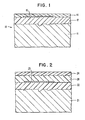
- FIG. 2 represents the cross-section of an alternative disk structure which overcomes this problem.
- a substrate 21 carries a dielectric layer 22 with a thin film servo pattern 25 thereon.
- the servo pattern 25 and layer 22 are covered with another dielectric layer 26 which in turn is covered with the magnetic medium film 24.
- the magnetic medium is separated from the servo pattern 25 which is advantageous because the dielectric layer 26 can further enhance the smoothness and adhesion of the magnetic medium 24.
- the dielectric layer 26 can also enhance the optical contrast of the pattern.
Abstract
Description
- This invention relates to magnetic record disks.
- Previously servo data has been recorded by making patterns in the magnetic recording portions of the disk, causing mechanical discontinuities in the magnetic recording media. For example, in one case, the magnetic recording media was etched to form the servo control patterns. Such servo patterns reduce the bit storage density and/or increase the error rate, although the error rate can be minimised if the storage density is sufficiently low that the bit patterns of the servo control signal become innocuous because they are small relative to the size of the magnetic recording data storage area for a single bit of data.
- In IEEE Transactions on Magnetics Volume MAG 16 pp631 to 633 (Sep 1980), there is described a magnetic record disk with a servo recording in the form of alternately coloured and uncoloured circular tracks in an anode-oxidised substrate coating just below the magnetic recording medium.
- IBM Technical Disclosure Bulletin
Vol 21,No 10, p 4259-4260 (Mar 1979) describes a floppy magnetic record disk provided with an embossed, spiral groove for electrostatic servo control. - The invention seeks to provide a magnetic record disk with a servo recording which has a minimal effect on the recording and reading of data in the magnetic record medium of the disk.
- A magnetic record disk comprising a magnetic record medium supported on a dielectric substrate, the magnetic record medium having a flat surface, is characterised, according to the invention, by a patterned metallic servo track film disposed between the magnetic record medium and the dielectric substrate.
- Preferably, the servo track is adapted to be detected by means of a capacitive sensor.
- How the invention can be carried out will now be described by way of example, with reference to the accompanying drawings, in which:-
- FIG. 1 represents a cross-section of a magnetic record disk having an optical and capacitive servo track located beneath the magnetic record medium in accordance with this invention; and
- FIG. 2 represents a substrate carrying a dielectric layer with a thin film servo pattern formed on it.
- Referring to FIG. 1, a
magnetic record disk 10 includes arigid aluminium substrate 11 coated with alayer 12 of a polymeric, dielectric material. Thedielectric layer 12 is coated with a thin film of a metal such as aluminium from which is formed a patterned capacitive and opticallyreflective servo track 15. Next, alayer 14 of a magnetic recording medium is deposited upon thedielectric layer 12 and the metallicservo track film 15. Thedielectric layer 12 is preferably composed of a very similar material to the matrix of themagnetic recording medium 14. - The
disk 10 can be flexible and it is not necessary to have thedielectric layer 12 in every case. A flexible disk is especially attractive if thesubstrate 11 is composed of an insulating material or a poor conductor. Suitable dielectric materials forsubstrate 11 include polyethylene terephthalate, acetate, silicon, ceramic and glass. - FIG. 1 represents the cross-section of a finished
disk 10. Above analuminium alloy substrate 11 is deposited athin layer 12 of a dielectric material having a preferable thickness of from about 0.1 to 10 microns, with a typical thickness of about 3 microns. However, thelayer 12 can be up to about 150 microns thick. The dielectric oflayer 12 can be composed of materials such as epoxy-phenolic resin, polyurethane, or polyimide. The purpose ofdielectric layer 12 is to provide optical and capacitive (dielectric) contrast, which will facilitate reading of data stored either optically and/or capacitively. - Additionally,
layer 12 can provide a smooth layer on the surface of thesubstrate 11 and so the provision oflayer 12 can possibly eliminate the need for turning thesubstrate 11 on a milling machine or lapping machine to smooth the rough peaks (asperities) from the original surface ofsubstrate 11. - Preferably, the
dielectric layer 12 is chosen to be compatible with the material comprising themagnetic medium 14, in order to provide similar coefficients of expansion and contraction and to enhance adhesion of the two layers together. - The
recording medium 14 is composed of a particulate material (magnetic-oxide particles) dispersed in an epoxy-phenolic matrix. Thedielectric layer 12 is composed of an epoxy-phenolic preferably similar or identical to the matrix ofmedium 14. -
Magnetic recording medium 14 is composed of a matrix of polyurethane carrying magnetic particles. The polymericdielectric layer 12 is composed of polyurethane. - The
recording medium 14 is a sputtered thin film composed of a metal or iron oxide such as gamma iron oxide, Fe203. Thedielectric layer 12 is composed of polyimide because of its capacity to withstand high temperatures with little alteration of its chemical and electrical properties. The polyimide can be heated to 400 degrees C during sputtering of the iron oxide with substantially no measurable change in the composition or characteristics of thedielectric layer 12. The polyimide can also be heated in air up to 400 degrees C without damage. - The layer deposited on the
dielectric layer 12 is a patterned thinmetallic film 15 which preferably is composed of chromium.Film 15 is thick enough to ensure the conductivity typical of a metallic film, say 0.01 microns. An alternative metal forfilm 15 is aluminium. - Patterning of the film is achieved by means of a subtractive technique such as sputter etching or wet chemical etching using a mask or the like to protect the portions of metal to be retained, or by means of an additive vacuum deposition technique such as sputtering or evaporation in conjunction with the well known lift-off techniques of depositing over a layer of resist which has openings where the pattern is to remain on the substrate.
Film 15 is extremely thin, approximately the magnitude of the surface roughness on existing disks or less. The degree of roughness is that existing after buffing the top surface offilm 14. % - Preferably,
layer 15 is from 0.005 to 0.1 microns thick (gross) andlayer 14 is about from 0.1 to 3 microns thick (chosen for magnetic reasons). - The magnetic
recording medium film 14 is deposited in a standard manner, followed by the usual buffing and lubrication. - In the current state of the art of magnetic record disk files, a magnetic transducer head for reading and writing data is carried by a slider which flies over the
magnetic recording medium 14. In this case, the medium is adapted to include capacitive or optical indicia which can be employed to indicate the physical locations on the disk to a capacitive and/or optical sensor or sensors on the slider, so that the magnetic recording medium and head will not be required to include the location data required to operate the servo system which positions the slider and the heads it carries. - An advantage of the present invention is that the internal servo-control data on the disk disturbs or modulates the magnetic recording data in a read-record channel minimally.
- Another advantage of this invention is that it does not increase the effective flying height of the magnetic recording head relative to the magnetic recording medium, so that the magnetic recording resolution can be optimal.
- A third feature of this invention is that it is compatible with existing magnetic medium formulations as well as new magnetic medium formulations, including matrices of polyurethane, and polymeric underlayers.
- A fourth feature of this invention is that it provides the versatility of being compatible with servo read heads which operate on both the capacitive and the optical contrast principles.
- A fifth advantage of this invention is that the critical head-to-disk interface is unchanged in that the servo layer is buried below the magnetic recording medium so it does not affect lubrication, start-stop characteristics and glide height of the head.
- It should be understood that the term optical contrast is used here to denote both optical and other electromagnetic radiation to which the medium is transparent. Thus infrared, or ultraviolet light or other radiation outside the visual spectrum could be employed.
- A primary requirement of a magnetic recording disk is that the position pattern should not interfere with the process of magnetic recording. The effects can be measured directly by observing the amplitude modulation of higher frequency magnetically recorded data by the position-signal pattern of the metallic film.
- The modulation sidelobes of the magnetic signal recorded and read on a structure similar to FIG. 1 were determined experimentally to be 28db below the desired read signal amplitude. This low sidelobe amplitude was below the noise level of the wideband data channel. Its presence could be determined only by the use of a sweeping spectrum analyser. This low level of amplitude modulation indicated that the position signal pattern will not interfere with the magnetic recording or reading of data. This experiment used a magnetic medium having a thickness of 0.5 microns and a patterned film thickness of 0.025 microns. Furthermore, we note that the recording and playing of the very high frequency magnetic data, corresponding to the resolution limits of the media, takes place at the upper portion of the magnetic medium (near the recording head) away from the patterned metallic film.
- However, for extremely thin magnetic layers, and for very high resolutions, it may be required to isolate the magnetic medium by disposing it farther from the position signal pattern.
- FIG. 2 represents the cross-section of an alternative disk structure which overcomes this problem. A
substrate 21 carries adielectric layer 22 with a thinfilm servo pattern 25 thereon. Theservo pattern 25 andlayer 22 are covered with anotherdielectric layer 26 which in turn is covered with the magneticmedium film 24. In this way the magnetic medium is separated from theservo pattern 25 which is advantageous because thedielectric layer 26 can further enhance the smoothness and adhesion of themagnetic medium 24. In the case of optical sensing of the servo pattern, thedielectric layer 26 can also enhance the optical contrast of the pattern.
Claims (11)
Applications Claiming Priority (2)
| Application Number | Priority Date | Filing Date | Title |
|---|---|---|---|
| US49474383A | 1983-05-16 | 1983-05-16 | |
| US494743 | 1983-05-16 |
Publications (3)
| Publication Number | Publication Date |
|---|---|
| EP0125478A2 true EP0125478A2 (en) | 1984-11-21 |
| EP0125478A3 EP0125478A3 (en) | 1987-05-13 |
| EP0125478B1 EP0125478B1 (en) | 1991-10-09 |
Family
ID=23965776
Family Applications (1)
| Application Number | Title | Priority Date | Filing Date |
|---|---|---|---|
| EP84103878A Expired - Lifetime EP0125478B1 (en) | 1983-05-16 | 1984-04-09 | Magnetic record disk with internal servo track |
Country Status (3)
| Country | Link |
|---|---|
| EP (1) | EP0125478B1 (en) |
| JP (1) | JPS59213074A (en) |
| DE (1) | DE3485139D1 (en) |
Cited By (3)
| Publication number | Priority date | Publication date | Assignee | Title |
|---|---|---|---|---|
| EP0162349A2 (en) * | 1984-05-24 | 1985-11-27 | International Business Machines Corporation | A data recording medium |
| GB2196467A (en) * | 1986-10-11 | 1988-04-27 | London Weekend Television | Optical disc with added magnetic record/playback facility |
| US4931887A (en) * | 1988-02-01 | 1990-06-05 | International Business Machines Corporation | Capacitive measurement and control of the fly height of a recording slider |
Citations (1)
| Publication number | Priority date | Publication date | Assignee | Title |
|---|---|---|---|---|
| US3426337A (en) * | 1964-12-21 | 1969-02-04 | Ibm | Positioning system for random access device |
-
1984
- 1984-01-31 JP JP1458684A patent/JPS59213074A/en active Granted
- 1984-04-09 DE DE8484103878T patent/DE3485139D1/en not_active Expired - Fee Related
- 1984-04-09 EP EP84103878A patent/EP0125478B1/en not_active Expired - Lifetime
Patent Citations (1)
| Publication number | Priority date | Publication date | Assignee | Title |
|---|---|---|---|---|
| US3426337A (en) * | 1964-12-21 | 1969-02-04 | Ibm | Positioning system for random access device |
Non-Patent Citations (2)
| Title |
|---|
| IBM TECHNICAL DISCLOSURE BULLETIN, vol. 21, no. 10, March 1979, pages 4259-4260, New York, US; R.E. ACOSTA et al.: "Floppy disc embossing for servo applications" * |
| IEEE Transactions on Magnetics, September 1980, Volume MAG-16 Number 5, N. Koshino and S. Ogawa "optical method of the head positioning in magnetic disc system" p. 631-633; * |
Cited By (4)
| Publication number | Priority date | Publication date | Assignee | Title |
|---|---|---|---|---|
| EP0162349A2 (en) * | 1984-05-24 | 1985-11-27 | International Business Machines Corporation | A data recording medium |
| EP0162349A3 (en) * | 1984-05-24 | 1988-09-07 | International Business Machines Corporation | A data recording medium |
| GB2196467A (en) * | 1986-10-11 | 1988-04-27 | London Weekend Television | Optical disc with added magnetic record/playback facility |
| US4931887A (en) * | 1988-02-01 | 1990-06-05 | International Business Machines Corporation | Capacitive measurement and control of the fly height of a recording slider |
Also Published As
| Publication number | Publication date |
|---|---|
| DE3485139D1 (en) | 1991-11-14 |
| EP0125478B1 (en) | 1991-10-09 |
| JPH0355905B2 (en) | 1991-08-26 |
| EP0125478A3 (en) | 1987-05-13 |
| JPS59213074A (en) | 1984-12-01 |
Similar Documents
| Publication | Publication Date | Title |
|---|---|---|
| US4737877A (en) | Structure to provide optical and capacitive contrast on magnetic recording disk | |
| US4819091A (en) | High speed magnetic disk contact recording system | |
| US6583957B1 (en) | Magnetic hard disk having concentric magnetic tracks with flat surface and fabrication method thereof | |
| US5245493A (en) | Magnetic information storage apparatus including magnetic head and method for making magnetic head | |
| US5986851A (en) | Selective carbon overcoat of the trailing edge of MR sliders | |
| JP2004178794A (en) | Vertical magnetic discrete track recording disk | |
| US5722157A (en) | Method of making an induction and magnetoresistance type composite magnetic head | |
| US6858328B1 (en) | Master information support | |
| KR19980063655A (en) | Magnetic recording medium, magnetic recording and reproducing apparatus and manufacturing method of metal mold for molding disc | |
| CA1241741A (en) | Variable impedance contrast in data storage media | |
| KR20020010575A (en) | Buried servo patterned media | |
| JP2000306227A (en) | Magnetic recording medium | |
| EP0125478B1 (en) | Magnetic record disk with internal servo track | |
| US7497008B2 (en) | Method of fabricating a thin film magnetic sensor on a wafer | |
| EP0447081A1 (en) | Method of recording servo information | |
| US6172850B1 (en) | Floating type magnetic head with non-magnetic thin film coating pattern to reduce starting friction | |
| US20060250726A1 (en) | Shield structure in magnetic recording heads | |
| US5218499A (en) | Thin-film magnetic head for perpendicular magnetic recording having a magnetic member with grooves crossing at right angles formed in a principal surface thereof | |
| US6920021B2 (en) | Sunken electrical lead defined narrow track width magnetic head | |
| JPH0476171B2 (en) | ||
| US5835312A (en) | Magnetic head for use with a recording medium | |
| JP3443971B2 (en) | Magnetic recording signal reproduction method | |
| JPH0140402B2 (en) | ||
| JPH0444610A (en) | Composite thin film magnetic head and production of the head | |
| JPH0489616A (en) | Magnetic disk device and magnetic disk |
Legal Events
| Date | Code | Title | Description |
|---|---|---|---|
| PUAI | Public reference made under article 153(3) epc to a published international application that has entered the european phase |
Free format text: ORIGINAL CODE: 0009012 |
|
| AK | Designated contracting states |
Designated state(s): DE FR GB |
|
| 17P | Request for examination filed |
Effective date: 19841123 |
|
| PUAL | Search report despatched |
Free format text: ORIGINAL CODE: 0009013 |
|
| AK | Designated contracting states |
Kind code of ref document: A3 Designated state(s): DE FR GB |
|
| 17Q | First examination report despatched |
Effective date: 19881121 |
|
| GRAA | (expected) grant |
Free format text: ORIGINAL CODE: 0009210 |
|
| AK | Designated contracting states |
Kind code of ref document: B1 Designated state(s): DE FR GB |
|
| REF | Corresponds to: |
Ref document number: 3485139 Country of ref document: DE Date of ref document: 19911114 |
|
| ET | Fr: translation filed | ||
| PLBE | No opposition filed within time limit |
Free format text: ORIGINAL CODE: 0009261 |
|
| STAA | Information on the status of an ep patent application or granted ep patent |
Free format text: STATUS: NO OPPOSITION FILED WITHIN TIME LIMIT |
|
| 26N | No opposition filed | ||
| PGFP | Annual fee paid to national office [announced via postgrant information from national office to epo] |
Ref country code: GB Payment date: 19930324 Year of fee payment: 10 |
|
| PGFP | Annual fee paid to national office [announced via postgrant information from national office to epo] |
Ref country code: FR Payment date: 19930330 Year of fee payment: 10 |
|
| PGFP | Annual fee paid to national office [announced via postgrant information from national office to epo] |
Ref country code: DE Payment date: 19930428 Year of fee payment: 10 |
|
| PG25 | Lapsed in a contracting state [announced via postgrant information from national office to epo] |
Ref country code: GB Effective date: 19940409 |
|
| GBPC | Gb: european patent ceased through non-payment of renewal fee |
Effective date: 19940409 |
|
| PG25 | Lapsed in a contracting state [announced via postgrant information from national office to epo] |
Ref country code: FR Effective date: 19941229 |
|
| PG25 | Lapsed in a contracting state [announced via postgrant information from national office to epo] |
Ref country code: DE Effective date: 19950103 |
|
| REG | Reference to a national code |
Ref country code: FR Ref legal event code: ST |