EP0124190A2 - Method of generating an N-tone gray scale with a thermal ink jet printer, and apparatus therefor - Google Patents
Method of generating an N-tone gray scale with a thermal ink jet printer, and apparatus therefor Download PDFInfo
- Publication number
- EP0124190A2 EP0124190A2 EP84300464A EP84300464A EP0124190A2 EP 0124190 A2 EP0124190 A2 EP 0124190A2 EP 84300464 A EP84300464 A EP 84300464A EP 84300464 A EP84300464 A EP 84300464A EP 0124190 A2 EP0124190 A2 EP 0124190A2
- Authority
- EP
- European Patent Office
- Prior art keywords
- ink jet
- jet printer
- thermal ink
- pulses
- pulse
- Prior art date
- Legal status (The legal status is an assumption and is not a legal conclusion. Google has not performed a legal analysis and makes no representation as to the accuracy of the status listed.)
- Granted
Links
Images


Classifications
-
- B—PERFORMING OPERATIONS; TRANSPORTING
- B41—PRINTING; LINING MACHINES; TYPEWRITERS; STAMPS
- B41J—TYPEWRITERS; SELECTIVE PRINTING MECHANISMS, i.e. MECHANISMS PRINTING OTHERWISE THAN FROM A FORME; CORRECTION OF TYPOGRAPHICAL ERRORS
- B41J2/00—Typewriters or selective printing mechanisms characterised by the printing or marking process for which they are designed
- B41J2/005—Typewriters or selective printing mechanisms characterised by the printing or marking process for which they are designed characterised by bringing liquid or particles selectively into contact with a printing material
- B41J2/01—Ink jet
- B41J2/21—Ink jet for multi-colour printing
- B41J2/2121—Ink jet for multi-colour printing characterised by dot size, e.g. combinations of printed dots of different diameter
- B41J2/2128—Ink jet for multi-colour printing characterised by dot size, e.g. combinations of printed dots of different diameter by means of energy modulation
-
- H—ELECTRICITY
- H04—ELECTRIC COMMUNICATION TECHNIQUE
- H04N—PICTORIAL COMMUNICATION, e.g. TELEVISION
- H04N1/00—Scanning, transmission or reproduction of documents or the like, e.g. facsimile transmission; Details thereof
- H04N1/024—Details of scanning heads ; Means for illuminating the original
- H04N1/032—Details of scanning heads ; Means for illuminating the original for picture information reproduction
- H04N1/034—Details of scanning heads ; Means for illuminating the original for picture information reproduction using ink, e.g. ink-jet heads
-
- B—PERFORMING OPERATIONS; TRANSPORTING
- B41—PRINTING; LINING MACHINES; TYPEWRITERS; STAMPS
- B41J—TYPEWRITERS; SELECTIVE PRINTING MECHANISMS, i.e. MECHANISMS PRINTING OTHERWISE THAN FROM A FORME; CORRECTION OF TYPOGRAPHICAL ERRORS
- B41J2202/00—Embodiments of or processes related to ink-jet or thermal heads
- B41J2202/01—Embodiments of or processes related to ink-jet heads
- B41J2202/06—Heads merging droplets coming from the same nozzle
Definitions
- This invention is concerned with a method of generating an N-tone printed gray scale with a thermal ink jet printer, and apparatus therefor.
- Thermal ink jet printers are operative for emitting ink droplets as described in UK Patent Application No. 8217720. Such thermal ink jet printers emit single ink droplets onto a page to form printed characters. The utility of prior art thermal ink jet printers has been inhibited because of the difficulty involved in creating a printed gray scale.
- the present invention provides apparatus for applying a train of current pulse packets to a thermal ink jet printer, comprising a controller for issuing a control signal, and characterized by first generation means, coupled to the controller, for generating control pulses at a predetermined rate, for receiving the control signal, and for generating control pulses having widths determined from the control signal, and second generation means, coupled to the first generation means at an input and to the thermal ink jet printer at an output, for receiving the control pulses and for presenting packets of current pulses at the output, said packets of current pulses having a preselected pulse repetition rate greater than the reciprocal of a droplet break-off interval of the thermal ink jet printer, having a pulse packet rate determined from the control pulse rate, and having a number of pulses per packet determined from the width of the control pulse.
- the second generation means can produce the packets of current pulses at a rate which is less than or equal to a maximum single droplet emission rate of the thermal ink jet printer.
- the second generation means can produce the pulses at a preselected current pulse repetition rate which is greater than the reciprocal of the droplet break-off interval of the thermal ink jet printer.
- the second generation means is arranged to produce the current pulses so that they are located contiguously within the current pulse packet.
- the second generation means produces a pulseless blanking interval between current pulse packets which is greater than the droplet break-off interval.
- the number of current pulses per packet multiplied by the current pulse packet rate is less than or equal to the reciprocal of a bubble collapse time of the thermal ink jet printer.
- the controller comprises a microprocessor.
- the number of current pulses per packet is less than or equal to 16.
- the second generation means produces a current pulse rate which is less than the reciprocal of a bubble collapse time of the thermal ink jet printer and greater than a droplet recede time of the thermal ink jet printer.
- the present invention also provides a method of generating an N-time printed gray scale with a thermal ink jet printer, characterized by the steps of determining a desired number of pulses to provide a packet of pulses required to create a dot having a desired darkness tone, delaying for a blanking interval after application of a previous packet to the thermal ink jet printer, generating a packet containing the desired number of pulses and having a pulse repetition rate greater than the reciprocal of a droplet break-off interval for the thermal ink jet printer, and applying the packet to the thermal ink jet printer.
- the blanking interval is greater than a droplet break-off interval of the thermal ink jet printer.
- the steps are repeated at a pulse packet rate, and the pulse packet rate multiplied by an integer N is less than or equal to the reciprocal of a bubble collapse time of the thermal ink jet printer.
- the pulse packet rate is less than or equal to a maximum single droplet emission rate of the thermal ink jet printer.
- the pulses are located contiguously within the packet.
- the present invention also provides a method of generating an ink drop with a thermal ink jet printer, characterized by the steps of determining a required number of pulses necessary to cause emission of the drop, generating a pulse packet containing the required number of pulses at a pulse repetition rate which is less than the reciprocal of a bubble collapse time of the thermal ink jet printer and greater than the reciprocal of an ink recede time of the thermal ink jet printer, and applying the pulse packet to ink-drop producing means of the thermal ink jet printer.
- the steps may be repeated a plurality of times to cause emission of a plurality of drops and to provide a blanking interval greater than or equal to a droplet break-off interval of the thermal ink jet printer.
- a thermal ink jet printer is capable of providing a printed gray scale at a high printing speed.
- a packet of current pulses is applied to the resistor of a single ink jet to cause emission of a packet of droplets.
- the interval between individual pulses is long enough that bubble collapse may occur after application of each pulse, yet short enough that the droplets do not individually break off from the ink jet orifice.
- the individual droplets within the packet remain connected and merge in flight to form a single drop.
- the drop breaks off from the orifice only after emission of the last droplet in the packet.
- the drop emission rate can approach the single droplet emission rate without an increase in the probability of malfunction.
- a multi-tone gray scale is possible at drop emission rates which approach the maximum single droplet emission rate of the thermal ink jet printer.
- Figure 1 shows a thermal ink jet print head 1 which is constructed in accordance with the preferred embodiment of the present invention and which is described in the aforementioned UK Patent Application No. 8217720.
- a current pulse is applied through a resistor 5 via a conductor 11 and a ground line 15, the resistor 5 is resistively heated and a vapor bubble is created overlaying the resistor 5 in the ink within a channel 25.
- An impulse generated by the growth of the bubble causes the ink within an orifice 33 to move outwards and, consequently, a droplet of ink may be emitted from the orifice 33.
- FIG. 2 shows a thermal ink jet printer which is constructed in accordance with the preferred embodiment of the present invention utilizing the print head shown in Figure 1.
- Ink from a reservoir 43 fills the channel 25 by capillary action to overlay the resistor 5.
- a controller 47 which may comprise a microprocessor, instructs a pulser 45 to apply a current pulse to the resistor 5 in order to cause an ink droplet to be emitted from the orifice 33 onto a page 41.
- the maximum single droplet emission rate (the maximum rate at which single droplets are successfully emitted by single pulses) is roughly 10 kHz and bubble collapse occurs at a time less than 20 microseconds after application of a pulse. As the single droplet emission rate exceeds 10 kHz the probability of malfunction, which is typically caused by orifice wetting, increases dramatically.
- the pulse repetition rate of the pulser 45 must allow sufficient time between pulses for the individual bubbles created by resistor 5 to collapse.
- the bubble collapse time is less than 20 microseconds and, therefore, the maximum pulse repetition rate is approximately 50 kHz.
- the spacing between the pulses within a packet must be less than the droplet break-off interval so that the individual droplets do not break off from the orifice 33. This limit varies with the physical parameters of the print head and with the characteristics of the ink being used and will typically be less than the reciprocal of the maximum single droplet emission rate for a given set of conditions.
- a pulseless blanking interval between pulse packets must be greater than the droplet break-off interval to allow the drop created by a pulse packet to break off from the orifice 33.
- the pulser 45 may comprise first and second pulse generators 51 and 53 as shown in Figure 2.
- the controller 47 sets the gate width of the pulse generator 51, such as a Hewlett-Packard Co. model 8013B, and the number of pulses in a particular packet to be applied to the print head 1 is thereby specified.
- the repetition rate of the pulse generator 51 is set manually or by the controller 47 to specify the packet rate of the pulses applied to the print head 1.
- the output of the pulse generator 51 is connected to a gate input of the pulse generator 53 which may comprise, for example, a Hewlett-Packard Co. model 214B.
- the repetition rate of the pulse generator is set manually or by the controller 47 to specify the pulse repetition rate.
- the output of the pulse generator 53 is connected to the resistor 5 of the print head 1.
- the printer shown in Figure 2 utilizes a .076mm diameter nickel orifice 33, a .051mm thick channel 25, and a .076mm square 5 ohm unpassivated metallic glass resistor 5.
- An ink having a carrier comprising equal parts of water and diethylene glycol was used.
- the print head 1 has a maximum single droplet emission rate of roughly 10 kHz and individual droplet break-off occurs 45 microseconds after application of a pulse.
- the maximum single droplet emission rate, and hence the maximum pulse repetition rate was found to be 50 kHz.
- Pulse packets selectably containing from zero to N pulses were used to cause emission of drops containing from zero to N droplets. Therefore, the maximum pulse packet rate, and the maximum drop printing rate, was
- the maximum drop printing rate would be 2.74 kHz.
- the printer shown in Figure 2 was also operated with a slower pulse train, a three packet portion of which is shown in Figure 3, to generate a 16-tone gray scale.
- the pulse train comprised a series of pulse packets containing from zero to sixteen 1 ampere by 1 microsecond current pulses at a pulse repetition rate of 25 kHz.
- the individual pulses within each packet were located contiguously and the number of individual pulses contained in each packet was varied from zero to sixteen as commanded by the controller 47 to create a desired darkness tone of each particular printed dot.
- the maximum packet width was 640 microseconds.
- the pulse packet rate was 400 Hz with the result that the drop printing rate (the rate at which drops are emitted towards the page 41 to print dots) was also 400 Hz.
- FIG. 3 shows a series of three pulse packets containing 6, 4, and 2 pulses, respectively. The result of application of these pulse packets to the print head 1 was to cause emission of three separate drops from the orifice 33 with the three drops having a nominal volume ratio of 6:4:2.
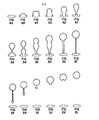
- Figures 4A to 4F show various stages of droplet formation at the orifice 33 within the first 40 microseconds after application of a single current pulse to the resistor 5.
- Figures 4A to 4D show that the bubble generated by the resistor 5 causes the ink meniscus within the orifice 33 to expand outwards.
- Figures 4E and 4F bubble collapse has occurred, an individual droplet has started to form, and a thin tail of ink remains attached to the ink meniscus. If no additional impulses were applied to the ink meniscus the individual droplet shown in Figure 4F would continue to move away from the orifice 33 and the tail would break with the result that the droplet would break off and move towards the page 41 as a discrete drop.
- Figures 5A to 5L show various stages of droplet formation when a second pulse is applied to resistor 5 at a time 40 microseconds after application of the initial pulse which created the droplet shown in Figures 4A to 4F. It should be understood that Figures 4A to 4F and Figures 5A to 5L depict one continuous formation process caused by the application of a packet of pulses and that this process may be extended with the use of a packet containing a larger number of pulses.
- Figures 5A to 5F show the effects of the application of a second pulse to the resistor 5 before the break-off of the droplet shown in Figure 4F.
- a second droplet is formed which merges with the first droplet to form a drop having approximately twice the volume of each of the two individual droplets.
- Figures 5G to 5L show the effects of break-off of the resultant drop from the orifice 33.
- the number of pulses is increased, the number of individual droplets increases and the resultant drop may become elongated because the final droplets are unable to fully merge with the first droplets. If the scan speed of the print head 1 relative to page 41 is increased, the elongated drops can be made to print elongated dots on the page 41.
- the printer shown in Figure 2 is also useful for causing successful droplet emission when a physically undersized resistor 5 for a particular ink is used.
- Droplet emission occurs when a bubble generated by the resistor 5 imparts enough of an impulse to the ink that a droplet moves out of the orifice 33 with a velocity sufficient to overcome the surface tension of the ink and to cause the droplet to break off from the meniscus. If an insufficient impulse is imparted by the bubble the droplet will progress through the stages shown in Figures 4A-D and will then recede back into the orifice 33.
- An insufficient impulse can be caused by the use of too small a resistor 5 for a particular ink since the size of the bubble is directly related to the physical size of the resistor 5.
- the printer shown in Figure 2 was used with a .102mm square metallic glass resistor 5 and a .046mm by .046mm silicon orifice 33.
- An ink carrier comprising formamide supplied by, e.g., the Aldrich Chemical Co.
- a 3 microsecond by 1.2 ampere pulse generated an optimal bubble but emission of a droplet did not occur and the ink which was protruded began to recede into the orifice 33 at a recede time which occurred 60 microseconds after application of the pulse. It was found that a 6 microsecond by 1.2 ampere pulse was also unable to cause ejection of an ink droplet.
Abstract
Description
- This invention is concerned with a method of generating an N-tone printed gray scale with a thermal ink jet printer, and apparatus therefor.
- Thermal ink jet printers are operative for emitting ink droplets as described in UK Patent Application No. 8217720. Such thermal ink jet printers emit single ink droplets onto a page to form printed characters. The utility of prior art thermal ink jet printers has been inhibited because of the difficulty involved in creating a printed gray scale.
- One prior art gray scale approach has been to aim multiple ink jets at one page location to allow variations in the darkness of a printed dot. This prior art approach requires a complex electromechanical system to coordinate the multiple jets. Another prior art approach, described in U.S. Patent No. 4,353,079, is to have a single ink jet emit a series of discrete droplets to form a single dot on the page. This prior art approach has the inherent problem that the speed at which dots may be printed on the page is seriously limited.
- The present invention provides apparatus for applying a train of current pulse packets to a thermal ink jet printer, comprising a controller for issuing a control signal, and characterized by first generation means, coupled to the controller, for generating control pulses at a predetermined rate, for receiving the control signal, and for generating control pulses having widths determined from the control signal, and second generation means, coupled to the first generation means at an input and to the thermal ink jet printer at an output, for receiving the control pulses and for presenting packets of current pulses at the output, said packets of current pulses having a preselected pulse repetition rate greater than the reciprocal of a droplet break-off interval of the thermal ink jet printer, having a pulse packet rate determined from the control pulse rate, and having a number of pulses per packet determined from the width of the control pulse.
- In apparatus as set forth in the last preceding paragraph, it is preferred that the second generation means can produce the packets of current pulses at a rate which is less than or equal to a maximum single droplet emission rate of the thermal ink jet printer.
- In apparatus as set forth in either one of the last two immediately preceding paragraphs, it is preferred that the second generation means can produce the pulses at a preselected current pulse repetition rate which is greater than the reciprocal of the droplet break-off interval of the thermal ink jet printer.
- In apparatus as set forth in any one of the last three immediately preceding paragraphs, it is preferred that the second generation means is arranged to produce the current pulses so that they are located contiguously within the current pulse packet.
- In apparatus as set forth in any one of the last four immediately preceding paragraphs, it is preferred that the second generation means produces a pulseless blanking interval between current pulse packets which is greater than the droplet break-off interval.
- In apparatus as set forth in any one of the last five immediately preceding paragraphs, it is preferred that the number of current pulses per packet multiplied by the current pulse packet rate is less than or equal to the reciprocal of a bubble collapse time of the thermal ink jet printer.
- In apparatus as set forth in any one of the last six immediately preceding paragraphs, it is preferred that the controller comprises a microprocessor.
- In apparatus as set forth in any one of the last seven immediately preceding paragraphs, it is preferred that the number of current pulses per packet is less than or equal to 16.
- In apparatus as set forth in any one of the last eight immediately preceding paragraphs, it is preferred that the second generation means produces a current pulse rate which is less than the reciprocal of a bubble collapse time of the thermal ink jet printer and greater than a droplet recede time of the thermal ink jet printer.
- The present invention also provides a method of generating an N-time printed gray scale with a thermal ink jet printer, characterized by the steps of determining a desired number of pulses to provide a packet of pulses required to create a dot having a desired darkness tone, delaying for a blanking interval after application of a previous packet to the thermal ink jet printer, generating a packet containing the desired number of pulses and having a pulse repetition rate greater than the reciprocal of a droplet break-off interval for the thermal ink jet printer, and applying the packet to the thermal ink jet printer.
- In carrying out a method as set forth in the last preceding paragraph, it is preferred that the blanking interval is greater than a droplet break-off interval of the thermal ink jet printer.
- In carrying out a method as set forth in the last preceding paragraph, it is preferred that the steps are repeated at a pulse packet rate, and the pulse packet rate multiplied by an integer N is less than or equal to the reciprocal of a bubble collapse time of the thermal ink jet printer.
- In carrying out a method as set forth in the last preceding paragraph, it is preferred that the pulse packet rate is less than or equal to a maximum single droplet emission rate of the thermal ink jet printer.
- In carrying out a method as set forth in the last preceding paragraph, it is preferred that the pulses are located contiguously within the packet.
- The present invention also provides a method of generating an ink drop with a thermal ink jet printer, characterized by the steps of determining a required number of pulses necessary to cause emission of the drop, generating a pulse packet containing the required number of pulses at a pulse repetition rate which is less than the reciprocal of a bubble collapse time of the thermal ink jet printer and greater than the reciprocal of an ink recede time of the thermal ink jet printer, and applying the pulse packet to ink-drop producing means of the thermal ink jet printer.
- The steps may be repeated a plurality of times to cause emission of a plurality of drops and to provide a blanking interval greater than or equal to a droplet break-off interval of the thermal ink jet printer.
- In accordance with the illustrated preferred embodiment of the present invention, a thermal ink jet printer is capable of providing a printed gray scale at a high printing speed. A packet of current pulses is applied to the resistor of a single ink jet to cause emission of a packet of droplets. The interval between individual pulses is long enough that bubble collapse may occur after application of each pulse, yet short enough that the droplets do not individually break off from the ink jet orifice. Thus, the individual droplets within the packet remain connected and merge in flight to form a single drop. The drop breaks off from the orifice only after emission of the last droplet in the packet. Since the probability of ink jet malfunction is related to the rate at which break-offs occur, by having only a single break-off for each packet, i.e., drop, the drop emission rate can approach the single droplet emission rate without an increase in the probability of malfunction. In the illustrated preferred embodiment of the present invention, a multi-tone gray scale is possible at drop emission rates which approach the maximum single droplet emission rate of the thermal ink jet printer.
- In the situation where a thermal ink jet printer is operated with a resistor which is undersized for a given ink, it is often the case that a single current pulse is insufficient to cause emission of an ink droplet. The illustrated preferred embodiment of the present invention is useful, in this situation, for providing a pulse packet in which the impulses generated by the individual pulses are combined to cause emission of a single ink drop.
- There now follows a detailed description, which is to be read with reference to the accompanying drawings, of apparatus according to the invention and a method according to the invention; it is to be clearly understood that both apparatus and method have been selected for description to illustrate the invention by way of example and not by way of limitation.
- In the accompanying drawings:-
- Figure 1 shows a thermal ink jet print head which is constructed in accordance with the preferred embodiment of the present invention;
- Figure 2 shows a thermal ink jet printer which is constructed in accordance with the preferred embodiment of the present invention and which uses the print head shown in Figure 1;
- Figure 3 shows a pulse train of three pulse packets which is generated by the pulser shown in Figure 2!
- Figures 4A to 4F show various stages of initial droplet growth when a single current pulse is used in the thermal ink jet printer shown in Figure 2; and
- Figures 5A to 5L show droplet growth stages subsequent to those shown in Figures 4A to 4F when a pulse packet containing two current pulses is used in the thermal ink jet printer shown in Figure 2.
- Figure 1 shows a thermal ink jet print head 1 which is constructed in accordance with the preferred embodiment of the present invention and which is described in the aforementioned UK Patent Application No. 8217720. When a current pulse is applied through a resistor 5 via a conductor 11 and a
ground line 15, the resistor 5 is resistively heated and a vapor bubble is created overlaying the resistor 5 in the ink within achannel 25. An impulse generated by the growth of the bubble causes the ink within anorifice 33 to move outwards and, consequently, a droplet of ink may be emitted from theorifice 33. - Figure 2 shows a thermal ink jet printer which is constructed in accordance with the preferred embodiment of the present invention utilizing the print head shown in Figure 1. Ink from a reservoir 43 fills the
channel 25 by capillary action to overlay the resistor 5. Acontroller 47, which may comprise a microprocessor, instructs apulser 45 to apply a current pulse to the resistor 5 in order to cause an ink droplet to be emitted from theorifice 33 onto a page 41. In typical prior art printers the maximum single droplet emission rate (the maximum rate at which single droplets are successfully emitted by single pulses) is roughly 10 kHz and bubble collapse occurs at a time less than 20 microseconds after application of a pulse. As the single droplet emission rate exceeds 10 kHz the probability of malfunction, which is typically caused by orifice wetting, increases dramatically. - The pulse repetition rate of the
pulser 45 must allow sufficient time between pulses for the individual bubbles created by resistor 5 to collapse. For the print head 1 the bubble collapse time is less than 20 microseconds and, therefore, the maximum pulse repetition rate is approximately 50 kHz. Further, in order to allow the individual droplets within a packet to merge into a single drop, the spacing between the pulses within a packet must be less than the droplet break-off interval so that the individual droplets do not break off from theorifice 33. This limit varies with the physical parameters of the print head and with the characteristics of the ink being used and will typically be less than the reciprocal of the maximum single droplet emission rate for a given set of conditions. A pulseless blanking interval between pulse packets must be greater than the droplet break-off interval to allow the drop created by a pulse packet to break off from theorifice 33. - The
pulser 45 may comprise first andsecond pulse generators controller 47 sets the gate width of thepulse generator 51, such as a Hewlett-Packard Co. model 8013B, and the number of pulses in a particular packet to be applied to the print head 1 is thereby specified. The repetition rate of thepulse generator 51 is set manually or by thecontroller 47 to specify the packet rate of the pulses applied to the print head 1. The output of thepulse generator 51 is connected to a gate input of thepulse generator 53 which may comprise, for example, a Hewlett-Packard Co. model 214B. The repetition rate of the pulse generator is set manually or by thecontroller 47 to specify the pulse repetition rate. The output of thepulse generator 53 is connected to the resistor 5 of the print head 1. - The printer shown in Figure 2 utilizes a .076mm
diameter nickel orifice 33, a .051mmthick channel 25, and a .076mm square 5 ohm unpassivated metallic glass resistor 5. An ink having a carrier comprising equal parts of water and diethylene glycol was used. Under these conditions, the print head 1 has a maximum single droplet emission rate of roughly 10 kHz and individual droplet break-off occurs 45 microseconds after application of a pulse. The maximum single droplet emission rate, and hence the maximum pulse repetition rate, was found to be 50 kHz. Pulse packets selectably containing from zero to N pulses were used to cause emission of drops containing from zero to N droplets. Therefore, the maximum pulse packet rate, and the maximum drop printing rate, was -

- The printer shown in Figure 2 was also operated with a slower pulse train, a three packet portion of which is shown in Figure 3, to generate a 16-tone gray scale. The pulse train comprised a series of pulse packets containing from zero to sixteen 1 ampere by 1 microsecond current pulses at a pulse repetition rate of 25 kHz. The individual pulses within each packet were located contiguously and the number of individual pulses contained in each packet was varied from zero to sixteen as commanded by the
controller 47 to create a desired darkness tone of each particular printed dot. Thus, the maximum packet width was 640 microseconds. The pulse packet rate was 400 Hz with the result that the drop printing rate (the rate at which drops are emitted towards the page 41 to print dots) was also 400 Hz. A pulseless blanking interval ranging from 1.22-1.86 milliseconds existed between pulse packets. Figure 3 shows a series of three pulse packets containing 6, 4, and 2 pulses, respectively. The result of application of these pulse packets to the print head 1 was to cause emission of three separate drops from theorifice 33 with the three drops having a nominal volume ratio of 6:4:2. - Figures 4A to 4F show various stages of droplet formation at the
orifice 33 within the first 40 microseconds after application of a single current pulse to the resistor 5. Figures 4A to 4D show that the bubble generated by the resistor 5 causes the ink meniscus within theorifice 33 to expand outwards. In Figures 4E and 4F, bubble collapse has occurred, an individual droplet has started to form, and a thin tail of ink remains attached to the ink meniscus. If no additional impulses were applied to the ink meniscus the individual droplet shown in Figure 4F would continue to move away from theorifice 33 and the tail would break with the result that the droplet would break off and move towards the page 41 as a discrete drop. - Figures 5A to 5L show various stages of droplet formation when a second pulse is applied to resistor 5 at a time 40 microseconds after application of the initial pulse which created the droplet shown in Figures 4A to 4F. It should be understood that Figures 4A to 4F and Figures 5A to 5L depict one continuous formation process caused by the application of a packet of pulses and that this process may be extended with the use of a packet containing a larger number of pulses. Figures 5A to 5F show the effects of the application of a second pulse to the resistor 5 before the break-off of the droplet shown in Figure 4F. A second droplet is formed which merges with the first droplet to form a drop having approximately twice the volume of each of the two individual droplets. Figures 5G to 5L show the effects of break-off of the resultant drop from the
orifice 33. - As the number of pulses is increased, the number of individual droplets increases and the resultant drop may become elongated because the final droplets are unable to fully merge with the first droplets. If the scan speed of the print head 1 relative to page 41 is increased, the elongated drops can be made to print elongated dots on the page 41.
- The printer shown in Figure 2 is also useful for causing successful droplet emission when a physically undersized resistor 5 for a particular ink is used. Droplet emission occurs when a bubble generated by the resistor 5 imparts enough of an impulse to the ink that a droplet moves out of the
orifice 33 with a velocity sufficient to overcome the surface tension of the ink and to cause the droplet to break off from the meniscus. If an insufficient impulse is imparted by the bubble the droplet will progress through the stages shown in Figures 4A-D and will then recede back into theorifice 33. An insufficient impulse can be caused by the use of too small a resistor 5 for a particular ink since the size of the bubble is directly related to the physical size of the resistor 5. - The printer shown in Figure 2 was used with a .102mm square metallic glass resistor 5 and a .046mm by .
046mm silicon orifice 33. An ink carrier comprising formamide (supplied by, e.g., the Aldrich Chemical Co.) was used and it was found that a 3 microsecond by 1.2 ampere pulse generated an optimal bubble but emission of a droplet did not occur and the ink which was protruded began to recede into theorifice 33 at a recede time which occurred 60 microseconds after application of the pulse. It was found that a 6 microsecond by 1.2 ampere pulse was also unable to cause ejection of an ink droplet. In contrast, when a first 3 microsecond by 1.2 ampere pulse, which was applied at time t=0, was followed by a second 3 microsecond by 1.2 ampere pulse at time t=27 microseconds (before the first ink droplet began to recede back into the orifice 33) a drop having a diameter of .061mm was successfully emitted towards the page 41.
Claims (16)
Applications Claiming Priority (2)
| Application Number | Priority Date | Filing Date | Title |
|---|---|---|---|
| US490003 | 1983-04-29 | ||
| US06/490,003 US4503444A (en) | 1983-04-29 | 1983-04-29 | Method and apparatus for generating a gray scale with a high speed thermal ink jet printer |
Publications (3)
| Publication Number | Publication Date |
|---|---|
| EP0124190A2 true EP0124190A2 (en) | 1984-11-07 |
| EP0124190A3 EP0124190A3 (en) | 1986-03-19 |
| EP0124190B1 EP0124190B1 (en) | 1988-04-27 |
Family
ID=23946206
Family Applications (1)
| Application Number | Title | Priority Date | Filing Date |
|---|---|---|---|
| EP84300464A Expired EP0124190B1 (en) | 1983-04-29 | 1984-01-26 | Method of generating an n-tone gray scale with a thermal ink jet printer, and apparatus therefor |
Country Status (4)
| Country | Link |
|---|---|
| US (1) | US4503444A (en) |
| EP (1) | EP0124190B1 (en) |
| JP (1) | JPS59207265A (en) |
| DE (1) | DE3470691D1 (en) |
Cited By (9)
| Publication number | Priority date | Publication date | Assignee | Title |
|---|---|---|---|---|
| EP0422870A2 (en) * | 1989-10-10 | 1991-04-17 | Xaar Limited | Method of multi-tone printing |
| EP0609997A2 (en) * | 1993-02-05 | 1994-08-10 | Hewlett-Packard Company | Method of reducing drive energy in a high speed thermal ink jet printer |
| EP0679011A1 (en) * | 1994-04-20 | 1995-10-25 | Canon Kabushiki Kaisha | An ink jet recording method, recording apparatus, and information-processing system |
| WO1998008687A1 (en) * | 1996-08-27 | 1998-03-05 | Topaz Technologies, Inc. | Inkjet print head for producing variable volume droplets of ink |
| US6106092A (en) * | 1998-07-02 | 2000-08-22 | Kabushiki Kaisha Tec | Driving method of an ink-jet head |
| EP1072419A2 (en) * | 1999-07-27 | 2001-01-31 | Canon Kabushiki Kaisha | Liquid discharge method, liquid discharge head and liquid discharge apparatus |
| US6193343B1 (en) | 1998-07-02 | 2001-02-27 | Toshiba Tec Kabushiki Kaisha | Driving method of an ink-jet head |
| US6494556B1 (en) | 1999-08-18 | 2002-12-17 | Seiko Epson Corporation | Liquid jetting apparatus, method of driving the same, and computer-readable record medium storing the method |
| WO2015097535A3 (en) * | 2013-12-23 | 2015-08-20 | Jan Franck | Ink-jet printer and method for operating an ink-jet printer |
Families Citing this family (59)
| Publication number | Priority date | Publication date | Assignee | Title |
|---|---|---|---|---|
| US5285215A (en) * | 1982-12-27 | 1994-02-08 | Exxon Research And Engineering Company | Ink jet apparatus and method of operation |
| US4513299A (en) * | 1983-12-16 | 1985-04-23 | International Business Machines Corporation | Spot size modulation using multiple pulse resonance drop ejection |
| US5202659A (en) * | 1984-04-16 | 1993-04-13 | Dataproducts, Corporation | Method and apparatus for selective multi-resonant operation of an ink jet controlling dot size |
| CA1244714A (en) * | 1984-04-16 | 1988-11-15 | William J. Debonte | Method for selective multi-cycle resonant operation of an ink jet apparatus for controlling dot size |
| USRE37862E1 (en) | 1985-01-31 | 2002-10-01 | Thomas G. Hertz | Method and apparatus for high resolution ink jet printing |
| US4620196A (en) * | 1985-01-31 | 1986-10-28 | Carl H. Hertz | Method and apparatus for high resolution ink jet printing |
| CA1259853A (en) * | 1985-03-11 | 1989-09-26 | Lisa M. Schmidle | Multipulsing method for operating an ink jet apparatus for printing at high transport speeds |
| DE3620334A1 (en) * | 1985-06-21 | 1987-01-02 | Sharp Kk | PRINTING PROCESS |
| US4680645A (en) * | 1986-08-25 | 1987-07-14 | Hewlett-Packard Company | Method for rendering gray scale images with variable dot sizes |
| US4794410A (en) * | 1987-06-02 | 1988-12-27 | Hewlett-Packard Company | Barrier structure for thermal ink-jet printheads |
| US4969052A (en) * | 1988-05-11 | 1990-11-06 | Canon Kabushiki Kaisha | Image processing method and apparatus |
| JPH023312A (en) * | 1988-06-20 | 1990-01-08 | Canon Inc | Ink jet recording method |
| US4930018A (en) * | 1988-12-02 | 1990-05-29 | Hewlett-Packard Company | Method and system for enhancing the quality of both color and black and white images produced by ink jet printers |
| US4982199A (en) * | 1988-12-16 | 1991-01-01 | Hewlett-Packard Company | Method and apparatus for gray scale printing with a thermal ink jet pen |
| US5512922A (en) * | 1989-10-10 | 1996-04-30 | Xaar Limited | Method of multi-tone printing |
| JPH03154096A (en) * | 1989-11-13 | 1991-07-02 | Canon Inc | Method and device for generating pattern |
| US5170177A (en) * | 1989-12-15 | 1992-12-08 | Tektronix, Inc. | Method of operating an ink jet to achieve high print quality and high print rate |
| US5032850A (en) * | 1989-12-18 | 1991-07-16 | Tokyo Electric Co., Ltd. | Method and apparatus for vapor jet printing |
| EP0437106B1 (en) * | 1990-01-08 | 1995-01-25 | Tektronix Inc. | Method and apparatus for printing with ink drops of varying sizes using a drop-on-demand ink jet print head |
| US5036337A (en) * | 1990-06-22 | 1991-07-30 | Xerox Corporation | Thermal ink jet printhead with droplet volume control |
| JPH0564889A (en) * | 1990-12-14 | 1993-03-19 | Ricoh Co Ltd | Ink fly recording method and device and production of the device |
| JP3339724B2 (en) * | 1992-09-29 | 2002-10-28 | 株式会社リコー | Ink jet recording method and apparatus |
| US5557304A (en) * | 1993-05-10 | 1996-09-17 | Compaq Computer Corporation | Spot size modulatable ink jet printhead |
| US5495270A (en) * | 1993-07-30 | 1996-02-27 | Tektronix, Inc. | Method and apparatus for producing dot size modulated ink jet printing |
| DE69417315T2 (en) | 1993-07-30 | 1999-09-23 | Canon Kk | Inkjet printing device and inkjet printing method |
| US5689291A (en) * | 1993-07-30 | 1997-11-18 | Tektronix, Inc. | Method and apparatus for producing dot size modulated ink jet printing |
| US5606351A (en) * | 1994-06-20 | 1997-02-25 | Eastman Kodak Company | Altering the intensity of the color of ink jet droplets |
| US5757982A (en) | 1994-10-18 | 1998-05-26 | Hewlett-Packard Company | Quadrantal scaling of dot matrix data |
| DE69603037T2 (en) * | 1995-03-08 | 1999-10-21 | Hewlett Packard Co | Inkjet printer |
| US6142599A (en) * | 1995-06-29 | 2000-11-07 | Canon Kabushiki Kaisha | Method for ink-jet recording and an ink-jet recording apparatus |
| JPH09164683A (en) | 1995-11-27 | 1997-06-24 | Samsung Electronics Co Ltd | Print head for bubble jet printer |
| US6142607A (en) * | 1996-08-07 | 2000-11-07 | Minolta Co., Ltd. | Ink-jet recording head |
| US6042219A (en) * | 1996-08-07 | 2000-03-28 | Minolta Co., Ltd. | Ink-jet recording head |
| JPH10166567A (en) * | 1996-12-12 | 1998-06-23 | Minolta Co Ltd | Ink jet recorder |
| JPH10166576A (en) * | 1996-12-12 | 1998-06-23 | Minolta Co Ltd | Ink jet recording head, and ink jet recording device |
| JPH10202856A (en) * | 1997-01-20 | 1998-08-04 | Minolta Co Ltd | Ink jet recording head |
| JPH10202918A (en) * | 1997-01-21 | 1998-08-04 | Minolta Co Ltd | Ink jet recorder |
| JPH10202921A (en) * | 1997-01-22 | 1998-08-04 | Minolta Co Ltd | Ink jet recording head |
| US6053600A (en) * | 1997-01-22 | 2000-04-25 | Minolta Co., Ltd. | Ink jet print head having homogeneous base plate and a method of manufacture |
| JPH10211704A (en) | 1997-01-31 | 1998-08-11 | Minolta Co Ltd | Ink jet head and manufacture of ink-chamber forming member for ink jet head |
| US6193347B1 (en) | 1997-02-06 | 2001-02-27 | Hewlett-Packard Company | Hybrid multi-drop/multi-pass printing system |
| US6259463B1 (en) | 1997-10-30 | 2001-07-10 | Hewlett-Packard Company | Multi-drop merge on media printing system |
| US6154230A (en) | 1997-02-06 | 2000-11-28 | Hewlett-Packard Company | Fractional dot column correction for better pen-to-pen alignment during printing |
| US5923344A (en) | 1997-02-06 | 1999-07-13 | Hewlett-Packard Co. | Fractional dot column correction for scan axis alignment during printing |
| JP3262009B2 (en) | 1997-02-14 | 2002-03-04 | ミノルタ株式会社 | Image forming device |
| US6296350B1 (en) | 1997-03-25 | 2001-10-02 | Lexmark International, Inc. | Ink jet printer having driver circuit for generating warming and firing pulses for heating elements |
| GB9802871D0 (en) * | 1998-02-12 | 1998-04-08 | Xaar Technology Ltd | Operation of droplet deposition apparatus |
| US6375309B1 (en) * | 1997-07-31 | 2002-04-23 | Canon Kabushiki Kaisha | Liquid discharge apparatus and method for sequentially driving multiple electrothermal converting members |
| US6234613B1 (en) | 1997-10-30 | 2001-05-22 | Hewlett-Packard Company | Apparatus for generating small volume, high velocity ink droplets in an inkjet printer |
| US6193345B1 (en) * | 1997-10-30 | 2001-02-27 | Hewlett-Packard Company | Apparatus for generating high frequency ink ejection and ink chamber refill |
| AU769733B2 (en) * | 1998-02-12 | 2004-02-05 | Xaar Technology Limited | Operation of droplet deposition apparatus |
| JP3185981B2 (en) | 1998-06-10 | 2001-07-11 | セイコーエプソン株式会社 | Ink jet recording apparatus and ink jet recording head driving method |
| US7155746B2 (en) * | 2002-12-27 | 2007-01-02 | Kimberly-Clark Worldwide, Inc. | Anti-wicking protective workwear and methods of making and using same |
| US6957884B2 (en) * | 2002-12-27 | 2005-10-25 | Kinberly-Clark Worldwide, Inc. | High-speed inkjet printing for vibrant and crockfast graphics on web materials or end-products |
| US6934969B2 (en) * | 2002-12-27 | 2005-08-30 | Kimberly-Clark Worldwide, Inc. | Anti-wicking protective workwear and methods of making and using same |
| US7943813B2 (en) | 2002-12-30 | 2011-05-17 | Kimberly-Clark Worldwide, Inc. | Absorbent products with enhanced rewet, intake, and stain masking performance |
| US8273066B2 (en) | 2003-07-18 | 2012-09-25 | Kimberly-Clark Worldwide, Inc. | Absorbent article with high quality ink jet image produced at line speed |
| US7178499B2 (en) * | 2003-07-28 | 2007-02-20 | General Electric Company | Locomotive engine governor low oil trip reset |
| WO2006046747A1 (en) * | 2004-10-28 | 2006-05-04 | Ricoh Company, Ltd. | Inkjet recording apparatus and inkjet recording method |
Citations (3)
| Publication number | Priority date | Publication date | Assignee | Title |
|---|---|---|---|---|
| GB1592834A (en) * | 1977-02-28 | 1981-07-08 | Ibm | Ink jet printing apparatus |
| US4339762A (en) * | 1979-04-02 | 1982-07-13 | Canon Kabushiki Kaisha | Liquid jet recording method |
| US4353079A (en) * | 1979-04-02 | 1982-10-05 | Canon Kabushiki Kaisha | Electronic device having a variable density thermal ink jet recorder |
Family Cites Families (3)
| Publication number | Priority date | Publication date | Assignee | Title |
|---|---|---|---|---|
| JPS57181875A (en) * | 1981-05-06 | 1982-11-09 | Nec Corp | Ink jet head and ink jet recording device |
| JPS5811169A (en) * | 1981-07-10 | 1983-01-21 | Canon Inc | Liquid-injection recording method |
| JPS6345308A (en) * | 1986-08-12 | 1988-02-26 | Agency Of Ind Science & Technol | Production of heat-resistant strength member of turbine by superplastic forging of different alloys |
-
1983
- 1983-04-29 US US06/490,003 patent/US4503444A/en not_active Expired - Lifetime
-
1984
- 1984-01-26 EP EP84300464A patent/EP0124190B1/en not_active Expired
- 1984-01-26 DE DE8484300464T patent/DE3470691D1/en not_active Expired
- 1984-04-20 JP JP59080020A patent/JPS59207265A/en active Granted
Patent Citations (3)
| Publication number | Priority date | Publication date | Assignee | Title |
|---|---|---|---|---|
| GB1592834A (en) * | 1977-02-28 | 1981-07-08 | Ibm | Ink jet printing apparatus |
| US4339762A (en) * | 1979-04-02 | 1982-07-13 | Canon Kabushiki Kaisha | Liquid jet recording method |
| US4353079A (en) * | 1979-04-02 | 1982-10-05 | Canon Kabushiki Kaisha | Electronic device having a variable density thermal ink jet recorder |
Cited By (19)
| Publication number | Priority date | Publication date | Assignee | Title |
|---|---|---|---|---|
| EP0422870A3 (en) * | 1989-10-10 | 1991-07-03 | Xaar Limited | Method of multi-tone printing |
| US5361084A (en) * | 1989-10-10 | 1994-11-01 | Xaar Limited | Method of multi-tone printing |
| EP0422870A2 (en) * | 1989-10-10 | 1991-04-17 | Xaar Limited | Method of multi-tone printing |
| US5600349A (en) * | 1993-02-05 | 1997-02-04 | Hewlett-Packard Company | Method of reducing drive energy in a high speed thermal ink jet printer |
| EP0609997A2 (en) * | 1993-02-05 | 1994-08-10 | Hewlett-Packard Company | Method of reducing drive energy in a high speed thermal ink jet printer |
| EP0609997A3 (en) * | 1993-02-05 | 1995-04-12 | Hewlett Packard Co | Method of reducing drive energy in a high speed thermal ink jet printer. |
| US6099102A (en) * | 1994-04-20 | 2000-08-08 | Canon Kabushiki Kaisha | Ink jet recording method, recording apparatus, and information-processing system |
| EP0679011A1 (en) * | 1994-04-20 | 1995-10-25 | Canon Kabushiki Kaisha | An ink jet recording method, recording apparatus, and information-processing system |
| WO1998008687A1 (en) * | 1996-08-27 | 1998-03-05 | Topaz Technologies, Inc. | Inkjet print head for producing variable volume droplets of ink |
| US6106092A (en) * | 1998-07-02 | 2000-08-22 | Kabushiki Kaisha Tec | Driving method of an ink-jet head |
| US6193343B1 (en) | 1998-07-02 | 2001-02-27 | Toshiba Tec Kabushiki Kaisha | Driving method of an ink-jet head |
| EP1072419A2 (en) * | 1999-07-27 | 2001-01-31 | Canon Kabushiki Kaisha | Liquid discharge method, liquid discharge head and liquid discharge apparatus |
| EP1072419A3 (en) * | 1999-07-27 | 2001-10-10 | Canon Kabushiki Kaisha | Liquid discharge method, liquid discharge head and liquid discharge apparatus |
| US6409296B1 (en) | 1999-07-27 | 2002-06-25 | Canon Kabushiki Kaisha | Liquid discharge method, liquid discharge head and liquid discharge apparatus |
| US6494556B1 (en) | 1999-08-18 | 2002-12-17 | Seiko Epson Corporation | Liquid jetting apparatus, method of driving the same, and computer-readable record medium storing the method |
| WO2015097535A3 (en) * | 2013-12-23 | 2015-08-20 | Jan Franck | Ink-jet printer and method for operating an ink-jet printer |
| CN105848916A (en) * | 2013-12-23 | 2016-08-10 | 扬·弗兰克 | Ink-jet printer and method for operating an ink-jet printer |
| US9643427B2 (en) | 2013-12-23 | 2017-05-09 | Jan Franck | Ink-jet printer and method for operating an ink-jet printer |
| CN105848916B (en) * | 2013-12-23 | 2018-10-30 | 扬·弗兰克 | Ink-jet printer and method for running ink-jet printer |
Also Published As
| Publication number | Publication date |
|---|---|
| DE3470691D1 (en) | 1988-06-01 |
| EP0124190A3 (en) | 1986-03-19 |
| US4503444A (en) | 1985-03-05 |
| JPH0415735B2 (en) | 1992-03-18 |
| EP0124190B1 (en) | 1988-04-27 |
| JPS59207265A (en) | 1984-11-24 |
Similar Documents
| Publication | Publication Date | Title |
|---|---|---|
| EP0124190B1 (en) | Method of generating an n-tone gray scale with a thermal ink jet printer, and apparatus therefor | |
| EP0194852B1 (en) | Operating an ink jet apparatus | |
| US4266232A (en) | Voltage modulated drop-on-demand ink jet method and apparatus | |
| US4393384A (en) | Ink printhead droplet ejecting technique | |
| JP3320731B2 (en) | Technology for adjusting the drop volume of inkjet printer heads | |
| US5600349A (en) | Method of reducing drive energy in a high speed thermal ink jet printer | |
| US4982199A (en) | Method and apparatus for gray scale printing with a thermal ink jet pen | |
| US4523200A (en) | Method for operating an ink jet apparatus | |
| FI61837C (en) | TRYCKNING GENOM BLAECKSPRUTNING | |
| JP2881566B2 (en) | Multiple tone printing method | |
| US5202659A (en) | Method and apparatus for selective multi-resonant operation of an ink jet controlling dot size | |
| EP0437106A2 (en) | Method and apparatus for printing with ink drops of varying sizes using a drop-on-demand ink jet print head | |
| GB1571698A (en) | Ink jet printing | |
| JPS60157875A (en) | Ink-jet printer | |
| US5886716A (en) | Method and apparatus for variation of ink droplet velocity and droplet mass in thermal ink-jet print heads | |
| EP0259541A2 (en) | Method for printing gray scales with a thermal ink jet printer | |
| US6257685B1 (en) | Ink droplet ejecting method and apparatus | |
| EP0751873A1 (en) | Improvements relating to pulsed droplet deposition apparatus | |
| JP2000135800A (en) | Method for driving on-demand type multinozzle ink jet head | |
| EP0373894B1 (en) | Method and apparatus for gray scale printing with a thermal ink jet pen | |
| EP0090663A1 (en) | Method and apparatus for ejecting droplets of ink | |
| EP0150119A2 (en) | Ink-jet recording system capable of recording half-tones | |
| EP0531173A1 (en) | Method of driving an ink jet printer head and driving circuit | |
| JPH0764068B2 (en) | Liquid jet recording method and liquid jet recording apparatus | |
| US6309047B1 (en) | Exceeding the surface settling limit in acoustic ink printing |
Legal Events
| Date | Code | Title | Description |
|---|---|---|---|
| PUAI | Public reference made under article 153(3) epc to a published international application that has entered the european phase |
Free format text: ORIGINAL CODE: 0009012 |
|
| 17P | Request for examination filed |
Effective date: 19840131 |
|
| AK | Designated contracting states |
Designated state(s): DE FR GB |
|
| PUAL | Search report despatched |
Free format text: ORIGINAL CODE: 0009013 |
|
| RHK1 | Main classification (correction) |
Ipc: B41J 3/04 |
|
| AK | Designated contracting states |
Kind code of ref document: A3 Designated state(s): DE FR GB |
|
| 17Q | First examination report despatched |
Effective date: 19871013 |
|
| GRAA | (expected) grant |
Free format text: ORIGINAL CODE: 0009210 |
|
| AK | Designated contracting states |
Kind code of ref document: B1 Designated state(s): DE FR GB |
|
| REF | Corresponds to: |
Ref document number: 3470691 Country of ref document: DE Date of ref document: 19880601 |
|
| ET | Fr: translation filed | ||
| PLBE | No opposition filed within time limit |
Free format text: ORIGINAL CODE: 0009261 |
|
| STAA | Information on the status of an ep patent application or granted ep patent |
Free format text: STATUS: NO OPPOSITION FILED WITHIN TIME LIMIT |
|
| 26N | No opposition filed | ||
| REG | Reference to a national code |
Ref country code: GB Ref legal event code: 732E |
|
| REG | Reference to a national code |
Ref country code: GB Ref legal event code: IF02 |
|
| REG | Reference to a national code |
Ref country code: FR Ref legal event code: TP |
|
| PGFP | Annual fee paid to national office [announced via postgrant information from national office to epo] |
Ref country code: FR Payment date: 20021231 Year of fee payment: 20 |
|
| PGFP | Annual fee paid to national office [announced via postgrant information from national office to epo] |
Ref country code: GB Payment date: 20030122 Year of fee payment: 20 |
|
| PGFP | Annual fee paid to national office [announced via postgrant information from national office to epo] |
Ref country code: DE Payment date: 20030131 Year of fee payment: 20 |
|
| PG25 | Lapsed in a contracting state [announced via postgrant information from national office to epo] |
Ref country code: GB Free format text: LAPSE BECAUSE OF EXPIRATION OF PROTECTION Effective date: 20040125 |
|
| REG | Reference to a national code |
Ref country code: GB Ref legal event code: PE20 |