EP0123061A1 - Adsorption-dryer - Google Patents
Adsorption-dryer Download PDFInfo
- Publication number
- EP0123061A1 EP0123061A1 EP84102083A EP84102083A EP0123061A1 EP 0123061 A1 EP0123061 A1 EP 0123061A1 EP 84102083 A EP84102083 A EP 84102083A EP 84102083 A EP84102083 A EP 84102083A EP 0123061 A1 EP0123061 A1 EP 0123061A1
- Authority
- EP
- European Patent Office
- Prior art keywords
- compressed air
- chamber
- adsorbent
- dehumidified
- moisture
- Prior art date
- Legal status (The legal status is an assumption and is not a legal conclusion. Google has not performed a legal analysis and makes no representation as to the accuracy of the status listed.)
- Withdrawn
Links
Images
Classifications
-
- B—PERFORMING OPERATIONS; TRANSPORTING
- B01—PHYSICAL OR CHEMICAL PROCESSES OR APPARATUS IN GENERAL
- B01D—SEPARATION
- B01D53/00—Separation of gases or vapours; Recovering vapours of volatile solvents from gases; Chemical or biological purification of waste gases, e.g. engine exhaust gases, smoke, fumes, flue gases, aerosols
- B01D53/02—Separation of gases or vapours; Recovering vapours of volatile solvents from gases; Chemical or biological purification of waste gases, e.g. engine exhaust gases, smoke, fumes, flue gases, aerosols by adsorption, e.g. preparative gas chromatography
- B01D53/04—Separation of gases or vapours; Recovering vapours of volatile solvents from gases; Chemical or biological purification of waste gases, e.g. engine exhaust gases, smoke, fumes, flue gases, aerosols by adsorption, e.g. preparative gas chromatography with stationary adsorbents
- B01D53/0454—Controlling adsorption
-
- B—PERFORMING OPERATIONS; TRANSPORTING
- B01—PHYSICAL OR CHEMICAL PROCESSES OR APPARATUS IN GENERAL
- B01D—SEPARATION
- B01D53/00—Separation of gases or vapours; Recovering vapours of volatile solvents from gases; Chemical or biological purification of waste gases, e.g. engine exhaust gases, smoke, fumes, flue gases, aerosols
- B01D53/26—Drying gases or vapours
- B01D53/261—Drying gases or vapours by adsorption
-
- F—MECHANICAL ENGINEERING; LIGHTING; HEATING; WEAPONS; BLASTING
- F26—DRYING
- F26B—DRYING SOLID MATERIALS OR OBJECTS BY REMOVING LIQUID THEREFROM
- F26B21/00—Arrangements or duct systems, e.g. in combination with pallet boxes, for supplying and controlling air or gases for drying solid materials or objects
- F26B21/06—Controlling, e.g. regulating, parameters of gas supply
- F26B21/08—Humidity
- F26B21/083—Humidity by using sorbent or hygroscopic materials, e.g. chemical substances, molecular sieves
Definitions
- the invention relates to an adsorption dryer for compressed air saturated with moisture, consisting of at least two chambers filled with an adsorbent for the moisture, which can be switched on and off alternately by means of a valve control in the compressed air line leading to a consumer, the regeneration of the adsorbent not in the chamber switched on in the compressed air line by means of the valve control, a partial flow of the dehumidified compressed air is branched off from the outlet of the chamber switched on in the compressed air line via a branch line and is directed into the atmosphere via a throttle orifice through the chamber not located in the compressed air line.
- Adsorption dryers of this type are known and have proven themselves well in practice.
- the cycle time is set in such a way that sufficient drying is still guaranteed at the end of the cycle time at maximum air throughput.
- this mode of operation is uneconomical if the dryer is operated at a power which is lower than the maximum permissible.
- the inefficiency is in it started that the same amount of dried air is used to regenerate the adsorbent even at a lower output, although in this case a much smaller amount of air is only required for the regeneration.
- the invention has for its object to provide an adsorption dryer with which moisture-saturated compressed air can be dried more economically than before.
- This object is achieved in that, with a constant cycle time for the air to be supplied to the regeneration of the adsorbent in one chamber .., dehumidified air the cycle time for the compressed air to be supplied to the other chamber to be dehumidified by a control device depending on the temperature, the pressure and the Volume flow of the compressed air to be dehumidified is set, the control device corresponding to a programmed memory, in which the individual temperature levels are assigned times for the cycle, in the moisture content of the moisture-saturated compressed air at these temperature levels, and a computer which comprises these times with the associated pressure and volume flow are linked and from this the cycle time until a predetermined value of the capacity utilization of the adsorbent contained in the chamber is calculated.
- the invention is based on the knowledge that an adjustment of the cycle time corresponding to the moisture content of the compressed air to be dried has to be based primarily on the temperature of the compressed air, because between the temperature and the moisture content the pressure There is a non-linear relationship and pressure and volume flow can be taken into account as decisive parameters for the volume due to the linear relationship between moisture content and volume in a simple manner with an appropriate correction factor. Due to the inventive consideration of the various time-related factors that are decisive for the amount of moisture to be absorbed by the adsorbent, the cycle time is optimally set under all possible operating conditions so that the dried air diverted for regeneration is fully utilized.
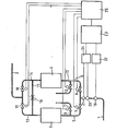
- a compressed air line 1, 2 From a compressed air source, not shown, moisture-saturated compressed air is passed via a compressed air line 1, 2 to a consumer, not shown.
- the compressed air line 1, 2 there are two chambers 3, 4 parallel to one another, which are filled with an adsorbent for moisture.
- the first part 1 of the compressed air line branches into two lines 5, 6, which each lead to a chamber 3 or 4.
- lines 9, 10 leading into the atmosphere are connected to these branch lines 5, 6, in which shut-off valves 11, 12 are also located.
- Output lines 13, 14, in which shut-off valves 15, 16 are also provided, open into the second part 2 of the compressed air line.
- the output lines 13, 14 are connected to one another via a connecting line 17 with a pressure reducing valve 18.
- valves 8, 11 and 16 are closed, so that the compressed air in the chamber 3 is dehumidified and the adsorbent is regenerated in the chamber 4.
- the control device to be described in detail is used to set the cycle time.
- the control device has a plurality of sensors 19 to 21, specifically for the temperature, the pressure and the volume flow for the compressed air to be dehumidified.
- the temperature sensor 19 supplies the temperature signal to a programmed memory 22.
- the non-linear relationship between temperature and moisture content is recorded in this memory. If a certain temperature is measured, the memory 22 supplies a signal for the cycle time corresponding to the moisture content of the compressed air at this temperature.
- This signal is linked to a signal for the volume in a computer 23. Since the volume depends on the pressure and the volume flow, these two values are converted into a signal corresponding to the volume in a computer 24.
- This conversion is expediently carried out in such a way that the time signal and the volume signal are based on the same reference pressure.
- the computer 23 with the time signal and the volume signal linked to one another also takes into account the time over which these signals are present and uses this to develop the cycle time that is required until the predetermined value of the capacity utilization of the adsorbent contained in one chamber is reached.
- This cycle time is converted in a power stage 25 into corresponding control signals for the individual valves 7, 8, 11, 12, 15, 16, so that the two chambers 3, 4 are operated in the change described above, the cycle time for the over the throttle diaphragm 18 of one or the other chamber 3 or 4 to be supplied, dehumidified air for the regeneration of the adsorbent is kept constant. In this way it is achieved that only the compressed air absolutely necessary for the regeneration of the adsorbent is consumed.
Abstract
Description
Die Erfindung bezieht sich auf einen Adsorptionstrockner für mit Feuchtigkeit gesättigte Druckluft, bestehend aus mindestens zwei mit einem Adsorptionsmittel für die Feuchtigkeit gefüllten Kammern, die mittels einer Ventilsteuerung im Takt abwechselnd in die zu einem Verbraucher führende Druckluftleitung einschaltbar sind, wobei zur Regeneration des Adsorptionsmittels der nicht in der Druckluftleitung eingeschalteten Kammer mittels der Ventilsteuerung vom Ausgang der in der Druckluftleitung eingeschalteten Kammer über eine Zweigleitung ein Teilstrom der entfeuchteten Druckluft abgezweigt und über eine Drosselblende durch die nicht in der Druckluftleitung liegende Kammer in die Atmosphäre geleitet wird.The invention relates to an adsorption dryer for compressed air saturated with moisture, consisting of at least two chambers filled with an adsorbent for the moisture, which can be switched on and off alternately by means of a valve control in the compressed air line leading to a consumer, the regeneration of the adsorbent not in the chamber switched on in the compressed air line by means of the valve control, a partial flow of the dehumidified compressed air is branched off from the outlet of the chamber switched on in the compressed air line via a branch line and is directed into the atmosphere via a throttle orifice through the chamber not located in the compressed air line.
Adsorptionstrockner dieser Art sind bekannt und haben sich in der Praxis gut bewährt. Die Taktzeit wird so eingestellt, daß bei maximalem Luftdurchsatz auch am Ende der Taktzeit noch eine ausreichende Trocknung gewährleistet ist. Diese Betriebsweise ist jedoch unwirtschaftlich, wenn der Trockner mit einer geringeren als der maximal zulässigen Leistung betrieben wird. Die Unwirtschaftlichkeit ist darin begündet, daß auch bei geringerer Leistung dieselbe getrocknete Luftmenge zur Regeneration des Adsorptionsmittels eingesetzt wird, obwohl in diesem Fall eine wesentlich geringere Luftmenge für die Regeneration nur benötigt wird.Adsorption dryers of this type are known and have proven themselves well in practice. The cycle time is set in such a way that sufficient drying is still guaranteed at the end of the cycle time at maximum air throughput. However, this mode of operation is uneconomical if the dryer is operated at a power which is lower than the maximum permissible. The inefficiency is in it started that the same amount of dried air is used to regenerate the adsorbent even at a lower output, although in this case a much smaller amount of air is only required for the regeneration.
Der Erfindung liegt die Aufgabe zugrunde, einen Adsorptionstrockner zu schaffen, mit dem feuchtigkeitsgesättigte Druckluft wirtschaftlicher als bisher getrocknet werden kann.The invention has for its object to provide an adsorption dryer with which moisture-saturated compressed air can be dried more economically than before.
Diese Aufgabe wird erfindungsgemäß dadurch gelöst, daß bei konstanter Taktzeit für die zur Regeneration des Adsorptionsmittels der einen Kammer zuzuführende.., entfeuchtete Luft die Taktzeit für die der anderen Kammer zuzuführende, zu entfeuchtende Druckluft von einer Steuereinrichtung in Abhängigkeit von der Temperatur dem Druck und dem Volumenstrom der zu entfeuchtenden Druckluft eingestellt wird, wobei die Steuereinrichtung einen programmierten Speicher, in dem den einzelnen Temperaturstufen Zeiten für den Takt zugeordnet sind, in dem Feuchtigkeitsgehalt der feuchtigkeitsgesättigten Druckluft bei diesen Temperaturstufen entsprechen, und einen Rechner umfaßt, der diese Zeiten mit dem zugehörigen Druck und Volumenstrom verknüpft und daraus die Taktzeit bis zum Erreichen- eines vorgegebenen Wertes der Kapazitätsausnutzung des in der Kammer enthaltenen Adsorptionsmittels errechnet.This object is achieved in that, with a constant cycle time for the air to be supplied to the regeneration of the adsorbent in one chamber .., dehumidified air the cycle time for the compressed air to be supplied to the other chamber to be dehumidified by a control device depending on the temperature, the pressure and the Volume flow of the compressed air to be dehumidified is set, the control device corresponding to a programmed memory, in which the individual temperature levels are assigned times for the cycle, in the moisture content of the moisture-saturated compressed air at these temperature levels, and a computer which comprises these times with the associated pressure and volume flow are linked and from this the cycle time until a predetermined value of the capacity utilization of the adsorbent contained in the chamber is calculated.
Die Erfindung beruht auf der Erkenntnis, daß eine dem Feuchtigkeitsgehalt der zu trocknenden Druckluft entsprechende Einstellung der Taktzeit sich vorrangig an der Temperatur der Druckluft zu orientieren hat, weil zwischen der Temperatur und dem Feuchtigkeitsgehalt der Druckluft ein nicht linearer Zusammenhang besteht und Druck und Volumenstrom als maßgebende Größen für das Volumen wegen der linearen Beziehung zwischen Feuchtigkeitsgehalt und Volumen auf einfache Art und Weise mit einem entsprechenden Korrekturfaktor berücksichtigt werden können. Aufgrund der erfindungsgemäßen Berücksichtigung der verschiedenen, auf die Zeit bezogenen, Faktoren, die für die vom Adsorptionsmittel aufzunehmende Feuchtigkeitsmenge maßgebend sind, wird unter allen möglichen Betriebsbedingungen die Taktzeit optimal eingestellt, so daß die für die Regeneration abgezweigte, getrocknete Luft voll ausgenutzt wird.The invention is based on the knowledge that an adjustment of the cycle time corresponding to the moisture content of the compressed air to be dried has to be based primarily on the temperature of the compressed air, because between the temperature and the moisture content the pressure There is a non-linear relationship and pressure and volume flow can be taken into account as decisive parameters for the volume due to the linear relationship between moisture content and volume in a simple manner with an appropriate correction factor. Due to the inventive consideration of the various time-related factors that are decisive for the amount of moisture to be absorbed by the adsorbent, the cycle time is optimally set under all possible operating conditions so that the dried air diverted for regeneration is fully utilized.
Im folgenden wird die Erfindung anhand einer Zeichnung näher erläutert, die schematisch einen Adsorptionstrockner zeigt.The invention is explained in more detail below with the aid of a drawing which schematically shows an adsorption dryer.
Von einer nicht dargestellten Druckluftquelle wird feuchtigkeitsgesättigte Druckluft über eine Druckluftleitung 1, 2 zu einem nicht dargestellten Verbraucher geleitet. In der Druckluftleitung 1, 2 liegen parallel zueinander zwei Kammern 3, 4, die mit einem Adsorptionsmittel für Feuchtigkeit gefüllt sind. Der erste Teil 1 der Druckluftleitung verzweigt sich in zwei Leitungen 5, 6, die jeweils zu einer Kammer 3 bzw. 4 führen. In jeder Zweigleitung 5, 6 liegt ein Absperrventil 7, 8. Ferner sind an diesen Abzweigleitungen 5, 6 in die Atmosphäre führende Leitungen 9, 10 angeschlossen, in denen ebenfalls Absperrventile 11, 12 liegen. Ausgangsleitungen 13, 14, in denen ebenfalls Absperrventile 15, 16 vorgesehen sind, münden in den zweiten Teil 2 der Druckluftleitung. Die Ausgangsleitungen 13, 14 sind über eine Verbindungsleitung 17 mit einem Druckminderventil 18 miteinander verbunden.From a compressed air source, not shown, moisture-saturated compressed air is passed via a
Ein solcher Adsorptionstrockner arbeitet auf folgende Art und Weise:
- Bei
geschlossenen Ventilen Leitung 17 und nach Entspannung durch dieDrosselblende 18 in dieKammer 3 und von hier über dieLeitung 9 in die Atmosphäre. Beim Durchströmen derKammer 3 wird dem Adsorptionsmittel die Feuchtigkeit entzogen und damit regeneriert.
- When the
valves line 17 and after expansion throughthrottle plate 18 intochamber 3 and from here vialine 9 into the atmosphere. When flowing through thechamber 3, the moisture is extracted from the adsorbent and thus regenerated.
Beim nächsten Takt werden die Ventile 8, 11 und 16 geschlossen, so daß die Druckluft in der Kammer 3 entfeuchtet wird und das Adsorptionsmittel in der Kammer 4 regeneriert wird.At the next cycle, the
Zur Einstellung der Taktzeit dient die noch im einzelnen zu beschreibende Steuereinrichtung. Die Steuereinrichtung weist mehrere Fühler 19 bis 21, und zwar für die Temperatur, den Druck und den Volumenstrom für die zu entfeuchtende Druckluft, auf. Der Temperaturfühler 19 liefert das Temperatursignal an einen programmierten Speicher.22. In diesem Speicher ist der nicht lineare Zusammenhang zwischen Temperatur und Feuchtigkeitsgehalt festgehalten. Wird eine bestimmte Temperatur gemessen, dann liefert der Speicher 22 ein dem Feuchtigkeitsgehalt der Druckluft bei dieser Temperatur entsprechendes Signal für die Taktzeit. Dieses Signal wird mit einem Signal für das Volumen in einem Rechner 23 verknüpft. Da das Volumen von dem Druck und dem Volumenstrom abhängt, werden diese beiden Werte' in ein dem Volumen entsprechendes Signal in einem Rechner 24 umgewandelt. Zweckmäßigerweise erfolgt diese Umwandlung derart, daß dem Zeitsignal und dem Volumensignal derselbe Bezugsdruck zugrunde gelegt wird. Der Rechner 23, der das Zeitsignal und das Volumensignal miteinander verknüpft, berücksichtigt außerdem die Zeit, über die diese Signale anstehen und entwickelt daraus die Taktzeit, die bis zum Erreichen des vorgegebenen Wertes der Kapazitätsausnutzung des in der einen Kammer enthaltenen Adsorptionsmittels benötigt wird. Diese Taktzeit wird in einer Leistungsstufe 25 in entsprechende Steuersignale für die einzelenen Ventile 7, 8, 11, 12, 15, 16 umgesetzt, damit die beiden..Kammern 3, 4 in dem oben beschriebenen Wechsel betrieben werden, wobei die Taktzeit für die über die Drosselblende 18 der einen oder anderen Kammer 3 bzw. 4 zuzuleitenden, entfeuchteten Luft für die Regeneration des Adsorptionsmittels konstant gehalten wird. Auf diese Art und Weise wird erreicht, daß nur die unbedingt für die Regeneration des Adsorptionsmittels erforderliche Druckluft verbraucht wird.The control device to be described in detail is used to set the cycle time. The control device has a plurality of
Claims (1)
Applications Claiming Priority (2)
| Application Number | Priority Date | Filing Date | Title |
|---|---|---|---|
| DE19833310842 DE3310842A1 (en) | 1983-03-25 | 1983-03-25 | ADSORPTION DRYER |
| DE3310842 | 1983-03-25 |
Publications (1)
| Publication Number | Publication Date |
|---|---|
| EP0123061A1 true EP0123061A1 (en) | 1984-10-31 |
Family
ID=6194595
Family Applications (1)
| Application Number | Title | Priority Date | Filing Date |
|---|---|---|---|
| EP84102083A Withdrawn EP0123061A1 (en) | 1983-03-25 | 1984-02-29 | Adsorption-dryer |
Country Status (3)
| Country | Link |
|---|---|
| EP (1) | EP0123061A1 (en) |
| DE (1) | DE3310842A1 (en) |
| DK (1) | DK136884A (en) |
Cited By (8)
| Publication number | Priority date | Publication date | Assignee | Title |
|---|---|---|---|---|
| EP0332724A1 (en) * | 1988-03-15 | 1989-09-20 | Pneumatech, Inc. | Gas drying method |
| FR2642668A1 (en) * | 1989-02-06 | 1990-08-10 | Trepaud Pierre | METHOD FOR REGENERATING AN ADSORBER OF A GAS DESICCATION PLANT AND INSTALLATION FOR CARRYING OUT THE SAME |
| BE1013951A3 (en) * | 2001-03-06 | 2003-01-14 | Atlas Copco Airpower Nv | Operation of compressed gas drying device involves using water load measured in gas drying compartment, to regulate desiccant regeneration |
| DE10302696A1 (en) * | 2003-01-24 | 2004-08-05 | Zander Aufbereitungstechnik Gmbh & Co. Kg | Adsorption dryer with integrated pre-filter |
| EP1701037A1 (en) * | 2005-03-01 | 2006-09-13 | Mann+Hummel Gmbh | Process for dehumidifying the air in the inlet suction flow of an air compressor |
| SG156587A1 (en) * | 2008-04-21 | 2009-11-26 | Air Prod & Chem | Improvements in cyclical swing adsorption processes |
| WO2021137127A1 (en) * | 2020-01-02 | 2021-07-08 | Atlas Copco Airpower, Naamloze Vennootschap | Method for drying compressed gas |
| BE1027873B1 (en) * | 2019-12-17 | 2021-07-15 | Atlas Copco Airpower Nv | Method of drying compressed gas |
Families Citing this family (3)
| Publication number | Priority date | Publication date | Assignee | Title |
|---|---|---|---|---|
| DE202004021123U1 (en) * | 2003-06-19 | 2007-03-08 | Werner Koch Maschinentechnik Gmbh | Device for drying plastic bulk material |
| DE102013109474A1 (en) * | 2013-08-30 | 2015-03-05 | Knorr-Bremse Systeme für Schienenfahrzeuge GmbH | Process and device for the regeneration of the desiccant of an adsorption air dryer |
| DE202016106099U1 (en) * | 2016-10-31 | 2016-11-22 | Hanno Lenke | Adsorption dryers for gases for industry |
Citations (2)
| Publication number | Priority date | Publication date | Assignee | Title |
|---|---|---|---|---|
| US3448561A (en) * | 1965-03-12 | 1969-06-10 | Pall Corp | Adsorbent fractionator with automatic cycle control and process |
| US4247311A (en) * | 1978-10-26 | 1981-01-27 | Pall Corporation | Downflow or upflow adsorbent fractionator flow control system |
-
1983
- 1983-03-25 DE DE19833310842 patent/DE3310842A1/en not_active Withdrawn
-
1984
- 1984-02-29 DK DK136884A patent/DK136884A/en not_active Application Discontinuation
- 1984-02-29 EP EP84102083A patent/EP0123061A1/en not_active Withdrawn
Patent Citations (2)
| Publication number | Priority date | Publication date | Assignee | Title |
|---|---|---|---|---|
| US3448561A (en) * | 1965-03-12 | 1969-06-10 | Pall Corp | Adsorbent fractionator with automatic cycle control and process |
| US4247311A (en) * | 1978-10-26 | 1981-01-27 | Pall Corporation | Downflow or upflow adsorbent fractionator flow control system |
Cited By (14)
| Publication number | Priority date | Publication date | Assignee | Title |
|---|---|---|---|---|
| EP0332724A1 (en) * | 1988-03-15 | 1989-09-20 | Pneumatech, Inc. | Gas drying method |
| FR2642668A1 (en) * | 1989-02-06 | 1990-08-10 | Trepaud Pierre | METHOD FOR REGENERATING AN ADSORBER OF A GAS DESICCATION PLANT AND INSTALLATION FOR CARRYING OUT THE SAME |
| EP0382611A1 (en) * | 1989-02-06 | 1990-08-16 | Pierre Trepaud | Method and apparatus for regenerating an adsorber of a gas dessication installation |
| US5037458A (en) * | 1989-02-06 | 1991-08-06 | Pierre Trepaud | Apparatus for regenerating an adsorber in a gas drying plant |
| BE1013951A3 (en) * | 2001-03-06 | 2003-01-14 | Atlas Copco Airpower Nv | Operation of compressed gas drying device involves using water load measured in gas drying compartment, to regulate desiccant regeneration |
| DE10302696B4 (en) * | 2003-01-24 | 2006-06-14 | Zander Aufbereitungstechnik Gmbh & Co. Kg | Adsorption dryer with integrated pre-filter |
| DE10302696A1 (en) * | 2003-01-24 | 2004-08-05 | Zander Aufbereitungstechnik Gmbh & Co. Kg | Adsorption dryer with integrated pre-filter |
| EP1701037A1 (en) * | 2005-03-01 | 2006-09-13 | Mann+Hummel Gmbh | Process for dehumidifying the air in the inlet suction flow of an air compressor |
| SG156587A1 (en) * | 2008-04-21 | 2009-11-26 | Air Prod & Chem | Improvements in cyclical swing adsorption processes |
| US7846237B2 (en) | 2008-04-21 | 2010-12-07 | Air Products And Chemicals, Inc. | Cyclical swing adsorption processes |
| BE1027873B1 (en) * | 2019-12-17 | 2021-07-15 | Atlas Copco Airpower Nv | Method of drying compressed gas |
| WO2021137127A1 (en) * | 2020-01-02 | 2021-07-08 | Atlas Copco Airpower, Naamloze Vennootschap | Method for drying compressed gas |
| BE1027959B1 (en) * | 2020-01-02 | 2021-08-05 | Atlas Copco Airpower Nv | Method of drying compressed gas |
| US11857917B2 (en) | 2020-01-02 | 2024-01-02 | Atlas Copco Airpower, Naamloze Vennootschap | Method for drying compressed gas |
Also Published As
| Publication number | Publication date |
|---|---|
| DE3310842A1 (en) | 1984-10-04 |
| DK136884D0 (en) | 1984-02-29 |
| DK136884A (en) | 1984-09-26 |
Similar Documents
| Publication | Publication Date | Title |
|---|---|---|
| DE3911574C2 (en) | Method and apparatus for drying or fractionating gas | |
| EP0123061A1 (en) | Adsorption-dryer | |
| US4559065A (en) | Twin tower gas fractionation apparatus | |
| DE3525083A1 (en) | DEVICE FOR DRYING COMPRESSED AIR | |
| DE2309197A1 (en) | METHOD AND EQUIPMENT FOR PURIFYING A FLOW OF A POLLUTED GAS | |
| DE3814175A1 (en) | METHOD AND ARRANGEMENT FOR REGENERATING ADSORPTION MATERIAL | |
| DE3637370C1 (en) | Method for feeding gas stored in a cavern storage system into a consumer network and arrangement for carrying out such a method | |
| EP0162140A1 (en) | Device for producing a continuous stream of dried gas for a drying funnel | |
| DE1919557C3 (en) | Method and device for separating one or more components from gas mixtures by selective adsorption and subsequent desorption | |
| EP0058189A1 (en) | Process and device for drying humid substances. | |
| DE3915673C2 (en) | ||
| DE69924779T2 (en) | Process for separating a gas mixture by adsorption | |
| EP0038410B1 (en) | Device for the separation or fractionated purification of gas mixtures | |
| DE69822767T2 (en) | Method for gas separation by adsorption with variable production rate | |
| WO2010081716A1 (en) | Device for the sorptive separation of a gas flow with a vortex tube for regeneration | |
| EP3439765A1 (en) | Air treatment device and air treatment method | |
| DE20321621U1 (en) | Device for generating an artificial atmosphere in a storage or transport container | |
| DE3702845C2 (en) | ||
| DE69918773T2 (en) | Pressure swing adsorption device using valves with high and heterogeneous operating time | |
| DE2531633C3 (en) | Device for drying gas | |
| DE2915336C2 (en) | Cold regenerable adsorption dryer | |
| EP0358962B1 (en) | Adsorption dryer | |
| EP1923649A2 (en) | Method for drying a material to be dried and plant for carrying out the method | |
| EP0383010A2 (en) | Heat-regenerating adsorption plant for humid gaseous media | |
| DE4239615A1 (en) | Gas processing plant control system - controls cyclically operated adsorption dryer, esp. for compressed air drying |
Legal Events
| Date | Code | Title | Description |
|---|---|---|---|
| PUAI | Public reference made under article 153(3) epc to a published international application that has entered the european phase |
Free format text: ORIGINAL CODE: 0009012 |
|
| AK | Designated contracting states |
Designated state(s): AT BE CH DE FR GB IT LI LU NL SE |
|
| STAA | Information on the status of an ep patent application or granted ep patent |
Free format text: STATUS: THE APPLICATION HAS BEEN WITHDRAWN |
|
| 18W | Application withdrawn |
Withdrawal date: 19850316 |
|
| RIN1 | Information on inventor provided before grant (corrected) |
Inventor name: ZANDER, BERND |