EP0122816A2 - Optical focus position control in an optical memory system - Google Patents
Optical focus position control in an optical memory system Download PDFInfo
- Publication number
- EP0122816A2 EP0122816A2 EP84302661A EP84302661A EP0122816A2 EP 0122816 A2 EP0122816 A2 EP 0122816A2 EP 84302661 A EP84302661 A EP 84302661A EP 84302661 A EP84302661 A EP 84302661A EP 0122816 A2 EP0122816 A2 EP 0122816A2
- Authority
- EP
- European Patent Office
- Prior art keywords
- tracking
- optical
- control device
- focus position
- parallel
- Prior art date
- Legal status (The legal status is an assumption and is not a legal conclusion. Google has not performed a legal analysis and makes no representation as to the accuracy of the status listed.)
- Granted
Links
Images

Classifications
-
- G—PHYSICS
- G11—INFORMATION STORAGE
- G11B—INFORMATION STORAGE BASED ON RELATIVE MOVEMENT BETWEEN RECORD CARRIER AND TRANSDUCER
- G11B7/00—Recording or reproducing by optical means, e.g. recording using a thermal beam of optical radiation by modifying optical properties or the physical structure, reproducing using an optical beam at lower power by sensing optical properties; Record carriers therefor
- G11B7/08—Disposition or mounting of heads or light sources relatively to record carriers
- G11B7/09—Disposition or mounting of heads or light sources relatively to record carriers with provision for moving the light beam or focus plane for the purpose of maintaining alignment of the light beam relative to the record carrier during transducing operation, e.g. to compensate for surface irregularities of the latter or for track following
- G11B7/0925—Electromechanical actuators for lens positioning
- G11B7/0932—Details of sprung supports
-
- G—PHYSICS
- G11—INFORMATION STORAGE
- G11B—INFORMATION STORAGE BASED ON RELATIVE MOVEMENT BETWEEN RECORD CARRIER AND TRANSDUCER
- G11B11/00—Recording on or reproducing from the same record carrier wherein for these two operations the methods are covered by different main groups of groups G11B3/00 - G11B7/00 or by different subgroups of group G11B9/00; Record carriers therefor
- G11B11/10—Recording on or reproducing from the same record carrier wherein for these two operations the methods are covered by different main groups of groups G11B3/00 - G11B7/00 or by different subgroups of group G11B9/00; Record carriers therefor using recording by magnetic means or other means for magnetisation or demagnetisation of a record carrier, e.g. light induced spin magnetisation; Demagnetisation by thermal or stress means in the presence or not of an orienting magnetic field
- G11B11/105—Recording on or reproducing from the same record carrier wherein for these two operations the methods are covered by different main groups of groups G11B3/00 - G11B7/00 or by different subgroups of group G11B9/00; Record carriers therefor using recording by magnetic means or other means for magnetisation or demagnetisation of a record carrier, e.g. light induced spin magnetisation; Demagnetisation by thermal or stress means in the presence or not of an orienting magnetic field using a beam of light or a magnetic field for recording by change of magnetisation and a beam of light for reproducing, i.e. magneto-optical, e.g. light-induced thermomagnetic recording, spin magnetisation recording, Kerr or Faraday effect reproducing
- G11B11/10502—Recording on or reproducing from the same record carrier wherein for these two operations the methods are covered by different main groups of groups G11B3/00 - G11B7/00 or by different subgroups of group G11B9/00; Record carriers therefor using recording by magnetic means or other means for magnetisation or demagnetisation of a record carrier, e.g. light induced spin magnetisation; Demagnetisation by thermal or stress means in the presence or not of an orienting magnetic field using a beam of light or a magnetic field for recording by change of magnetisation and a beam of light for reproducing, i.e. magneto-optical, e.g. light-induced thermomagnetic recording, spin magnetisation recording, Kerr or Faraday effect reproducing characterised by the transducing operation to be executed
- G11B11/10504—Recording
-
- G—PHYSICS
- G11—INFORMATION STORAGE
- G11B—INFORMATION STORAGE BASED ON RELATIVE MOVEMENT BETWEEN RECORD CARRIER AND TRANSDUCER
- G11B11/00—Recording on or reproducing from the same record carrier wherein for these two operations the methods are covered by different main groups of groups G11B3/00 - G11B7/00 or by different subgroups of group G11B9/00; Record carriers therefor
- G11B11/10—Recording on or reproducing from the same record carrier wherein for these two operations the methods are covered by different main groups of groups G11B3/00 - G11B7/00 or by different subgroups of group G11B9/00; Record carriers therefor using recording by magnetic means or other means for magnetisation or demagnetisation of a record carrier, e.g. light induced spin magnetisation; Demagnetisation by thermal or stress means in the presence or not of an orienting magnetic field
- G11B11/105—Recording on or reproducing from the same record carrier wherein for these two operations the methods are covered by different main groups of groups G11B3/00 - G11B7/00 or by different subgroups of group G11B9/00; Record carriers therefor using recording by magnetic means or other means for magnetisation or demagnetisation of a record carrier, e.g. light induced spin magnetisation; Demagnetisation by thermal or stress means in the presence or not of an orienting magnetic field using a beam of light or a magnetic field for recording by change of magnetisation and a beam of light for reproducing, i.e. magneto-optical, e.g. light-induced thermomagnetic recording, spin magnetisation recording, Kerr or Faraday effect reproducing
- G11B11/1055—Disposition or mounting of transducers relative to record carriers
- G11B11/10576—Disposition or mounting of transducers relative to record carriers with provision for moving the transducers for maintaining alignment or spacing relative to the carrier
-
- G—PHYSICS
- G11—INFORMATION STORAGE
- G11B—INFORMATION STORAGE BASED ON RELATIVE MOVEMENT BETWEEN RECORD CARRIER AND TRANSDUCER
- G11B7/00—Recording or reproducing by optical means, e.g. recording using a thermal beam of optical radiation by modifying optical properties or the physical structure, reproducing using an optical beam at lower power by sensing optical properties; Record carriers therefor
- G11B7/08—Disposition or mounting of heads or light sources relatively to record carriers
- G11B7/09—Disposition or mounting of heads or light sources relatively to record carriers with provision for moving the light beam or focus plane for the purpose of maintaining alignment of the light beam relative to the record carrier during transducing operation, e.g. to compensate for surface irregularities of the latter or for track following
- G11B7/0925—Electromechanical actuators for lens positioning
- G11B7/093—Electromechanical actuators for lens positioning for focusing and tracking
Definitions
- the present invention relates to an optical focus position control device of an optical disc apparatus that records, plays back, and erases a variety of information by irradiating optical beams such as the laser beams onto a recording media.
- the present invention relates, more particularly, to an optical focus position control device in an opto-magnetic disc apparatus which records, plays back, and erases a variety of information by irradiating optical beams such as the laser beams onto a recording medium including a magnetic film.
- any of the existing optical discs easily causes its surface to vibrate during rotation, and as'a result, recording tracks on the disc are obliged to displace themselves in the direction of the optical axis of the incident laser beams that irradiate the disc surface. Also, being adversely affected by any deviation between the center position of the disc and the motor shaft that drives the disc, recording tracks of such a disc are then obliged to displace themselves in the direction of the disc radius (hereinafter called the radial direction).
- the radial direction a device is provided so that the laser beams focus position can be correctly followed up within the optical head mechanism to enable the incident laser beam spot to correctly match the recording tracks of a disc.
- Such a device is called the optical focus position control in the following description.
- any of the existing optical disc apparatus such as the one that only plays back information without containing any magnetic film recording media, or the other one that can record any additional information
- the focus controller in order to fine adjust the focus position of the incident laser beams (hereinafter called the focus controller) to deal with the disc displacement in the direction of the optical axis of the incident laser beams
- the focus controller to deal with the disc displacement in the radial direction
- a variety of mechanism that can fine adjust the focus position of the incident laser beams via the rotary mirror that reflects the incident laser beams against any optimum direction have been introduced.
- the above- mentioned tracking control is not practical because the incident laser beams innevitably incline from the parpendi- cular direction of the disc.
- said mechanism comprises a coil that can be moved integrally with an objective lens and a stationary permanent magnet, thus causing the objective lens to be displaced by the current flowing through said coil.
- an object of the present invention is to provide an improved mechanism for the optical focus position control device by minimizing any adverse effect of the leakage magnetism against the optical disc.
- Another object of the present invention is to securely achieve a mechanism that stably drives the objective lens in dual directions, i.e., either in the vertical (up/down) or horizontal (left/right) direction without causing the objective lens to incline by using an optical focus position controller capable of controlling both the tracking and focussing of an optical disc apparatus.
- Still another object of the present invention is to stabilize the tracking and focussing movement of the objective lens by improving the damping characteristics of the drive and support mechanism.
- a tracking control device for moving an objective lens-mirror cylinder in the radial direction, and a focus control device for moving the tracking control device in the direction of the optical axis of the incident laser beams are disposed in a stationary housing.
- the tracking control device includes a movable intermediate supporting unit.
- the objective lens-mirror cylinder is supported by the movable intermediate supporting unit via parallel springs which are movable only in the radial direction.
- the tracking control device further includes an electromagnetic drive unit for shifting the objective lens-mirror cylinder in the radial direction.
- the focus control device includes an electromagnetic drive unit for shifting the movable intermediate supporting unit in the direction of the optical axis.
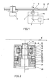
- Figure 1 shows a simplified block diagram of an optical disc apparatus as a preferred embodiment of the present infention.
- symbol 1 denotes a laser beam source that emits laser beams 2.
- Symbol 3 denotes a mirror, and symbol 4 denotes an objective lens that causes the laser beams 2 to be focussed onto the recording media surface of a disc.
- Symbol 5 denotes an optical focus position control device that causes the optical focus position to be accurately followed onto the tracks of the recording media of a disc by driving an objective lens 4 either in the vertical (up/down) or horizontal (left/right) direction.
- Symbol 6 denotes an optical head that contains all the optical devices mentioned above.
- Symbol 7 denotes a recording/erasing coil that provides that surface of the disc recording media with magnetism while either recording or erasing any information.
- Symbol 8 denotes an optical disc incorporating a disc recording media 8', and symbol 9 denotes motor that drives said optical disc to rotate.
- the focus control to be performed by the optical focus position control device 5, i.e., a fine adjustment of the incident laser beam focus position against the disc displacement made in the direction of the incident laser beam axis can be achieved by causing the objective lens 4 to move in the direction of the thickness of said optical disc 8.
- the tracking control to be performed by said optical focus position control device 5; i.e., a fine adjustment of the incidental laser beam focus position in dealing with the disc displacement in the radial direction can be performed by causing the objective lens 4 to move in the radial direction of the optical disc 8.
- FIGURE 2 shows a detailed construction of the optical focus position control system 5.
- An objective lens-mirror cylinder 10 supports the objective lens 4.
- the lens-mirror cylinder 10 is supported by a movable intermediate support member 11 via parallel springs 12 so that the lens-mirror cylinder 10 is movable in the radial (left/right), tracking direction with respect to the intermediate support member 11.
- a tracking permanent magnet 13, a tracking yoke plate 14 amd a tracking yoke 15 are secured to the intermediate support member 11, and form, in combination, a closed magnetic circuit.
- a tracking magnetic space 16 is provided between the tracking yoke plate 14 and the tracking yoke 15.
- a tracking drive coil 17 is secured to the lens-mirror cylinder 10 across the tracking magnetic space 16.
- magnetism will be generated in the tracking drive coil 17, and as a result, due to a combined effect with the other magnetism generated by the tracking permanent magnet 13, all the tracking drive coil 17, the lens-mirror cylinder 10, the objective lens 4, and a counter balance 18 are displaced in the radial direction.
- the counter balance 18 is secured to the bottom of the lens-mirror cylinder 10 so that the tracking drive force is applied to the center of the gravity of the tracking movable elements.
- a focussing permanent magnet 19, a focussing yoke plate 20, and a focussing yoke 21 form, in combination, a closed magnetic circuit. These elements are securely installed to a stationary holder 25 which fully supports the optical focus position control device.
- a focussing magnetic space 22 is formed between the focussing yoke plate 20 and the focussing yoke 21.
- a focus drive coil 23 is secured to the movable intermediate support member 11 across the focussing magnetic space 22.
- the mobable intermediate support member 11 is supported by the stationary holder 25 via parallel springs 24 so that the movable intermediate support member 11 is movable in the vertical direction, namely, in the direction of the incident laser beam axis with respect to the stationary holder 25.
- the tracking controller is driven by the electromagnetic effect that interacts between the tracking closed magnetic circuit secured to the intermediate support member 11 and the tracking drive coil 17 secured to the objective lens-mirror cylinder 10.
- the intermediate support member 11 and the objective lens-mirror cylinder 10 are connected to each other via the elestic material that is workable only to the left and to the right by moving in the radial direction, i.e., via a parallel spring 12 that moves in the direction of the disc radius.
- the objective lens-mirror cylinder 10 will have a resonance frequency fT which is represented by a formula when the objective lens-mirror cylinder 10 moves to the left and to the right.
- the movement phase delay caused by the displacement XT of the objective lens-mirror cylinder 10 in the tracking direction is 0° through 90° when 0 ⁇ f ⁇ fT, or 90° through 180° when fT ⁇ f, or near 180° when fT «f.
- the delay in the movement phase caused by the displacement XT of the objective lens-mirror cylinder 10 moving to the tracking target position YT should remain below 180° throughout the frequency bands of the tracking control signal.
- a phase advancing compensation circuit is used to advance the phase of the tracking drive signal FT, the phase delay is properly maintained below 180°. This ensures a stable tracking control.
- the focussing controller is driven by the electromagnetic effect that interacts between the focussing closed magnetic circuit secured to the stationary holder 25 and the focussing drive coil 23 secured to the intermediate support member 11.
- the intermediate support member 11 and the stationary holder 25 are connected to each other via the parallel spring 24 which is workable only in the vertical direction by moving in the direction of focussing.
- the weight of the movable part in the direction of focussing including the tracking control device is MF
- the spring constant of the parallel spring 24 moving in the direction of focussing is KF
- the objective lens-mirror cylinder 10 will be provided with a resonance frequency which is represented by a formula (hereinafter called the primary resonance frequency ) when performing vertrical (up/down) movements.
- the interim holder 11 and the objective lens-mirror cylinder 10 are connected to each other via the parallel spring 12 moving in the tracking direction.
- the aprallel spring 12 slightly moves in the vertical direction due to its elasticity.
- the objective lens-mirror cylinder 10 will have a resonance frequency ( hereinafter called the secondary resonance frequency ) represented as
- the movement phase delay in the displacement XF caused by the objective lens-mirror 10 in the focussing direction can be represented to be 0° through 90° when 0 ⁇ f ⁇ fF, where f (Hz) represents a frequency, whereas such a delay in the movement phase can be represent to be 90° through 270° when fF ⁇ f ⁇ f'F, and it will be 270° through 360° when f'F ⁇ f.
- the delay in the movement phase caused by the displacement XF of the objective lens-mirror cylinder 10 moving to the focussing target position YF should remain below 180° throughout the frequency bands of the focussing control signal.
- the phase advancing compensation circuit is used to advance the phase of the focussing drive signal FF, since there is a certain limit for advancing the phase amount, the phase cannot be compensated for in order that it can exceed 180° significantly.
- the second resonance frequency fF should be set at an optimum level higher than the frequency band of the focussing control signal.
- frequency bands available for the focussing control signal are variable N according to uses, generally, an optical disc apparatus uses 1 through 4KHz of the frequency bands. As a result, it was made clear that the secondary resonance frequency f'F should be set at a level above 7KHz.
- the secondary resonance frequency f'F can be determined by the spring constant KT' of the tracking parallel spring 12 when it moves in the focussing direction and by the weight MT of the moving parts in the tracking direction.
- the secondary resonance frequency f'F becomes large as the spring constant KT' becomes large and as the weight MT becomes small.
- the weight MT of the parts moving in the tracking direction cannot be decreased significantly. (Normally, the weight MT is designed in a range from 0.5 to 10 grams.)
- the inventors followed up trials for increasing the spring constant KT' of the tracking parallel spring 12 during its movement in the vertical direction.
- the spring constant KT' in the vertical direction (up/down) can be increased,by expanding the length XT and decreasing the thickness YT of the parallel spring 12.
- the secondary resonance frequency f'F can be obtained by an equation
- the tracking parallel spring 12 should be designed so that it can be provided with 20 through 50 micron meter of the thickness YT and an actual length taht is 100 up to 500 times the thickness YT.
- the delay in the movement phase caused by the displacement XF of the objective lens 4 against the focussing target position can be decreased below 180° within the frequency bands available for the focussing control signal. It is important that the phase advancing compensation circuit be used for correctly compensating for the movement phase.
- the resonance frequencies fF and fT there are N two kinds of the resonance frequencies fF and fT when the tracking control device and the focus control device are operated. If the damping characteristics in the directions of focussing and tracking control remain negligible, the resonance multiple factor in the resonance frequencies fF and fT will grow, thus causing any interference vibration to easily occur during either the focussing or tracking control operation. Also, when a certain frequency above the resonance frequency level is fed, the phase in responding to the displacement of the movable parts will be extremely delayed to a point very close to 180°, which will result in an extremely unstable optical focus position control operation. To prevent this and ensure satisfactory amount of the damping characteristics, the present invention effectively provides the following means.
- the primary improvement includes a latexed damping member painted on the focussing parallel spring and/or the tracking parallel spring.
- the plate rubber attached to the metal spring by an adhesive is not suited for the device, because the spring constant becomes high due to the adhesive.
- viscose-elastic materials such as silicon rubber, butyl rubber, silicon-butyl rubber, and acrylic-ethylene rubber, foaming synthetic resin such as foamed polyurethane, and viscose fluid such as silicon grease, can be made available.
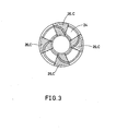
- FIGURE 3 shows a plane view of the focussing parallel spring 24.
- the focussing parallel spring 24 has a structure that connects two concentric circles, where two flat sheet springs, each being connected to four arms at the edges, are provided in the upper and lower positions.
- the parallel spring 24 moving in the direction of focus causes the intermediate holder 11 to move only in the vertical direction with respect to the stationary holder 25.(see FIGURE 2.)
- Damping material 26 is bonded to the portion C of the surface of the focussing parallel spring 24, where the largest amount of the relative displacement exists, thus resulting in greater damping characteristics in the direction of focus.
- viscose-elastic materials such as silicon-rubber, butyl rubber, silicon-butyl rubber, and acrylic-ethylene rubber, and foaming synthetic resin such as foamed polyurethane, can be made available.
- the third improvement is to form the focussing parallel spring and/or the tracking parallel spring with a vibration-proof alloy such as manganese-copper alloy, ferro-aluminum alloy, nickel-titanium alloy, and magnesium alloy.
- a vibration-proof alloy such as manganese-copper alloy, ferro-aluminum alloy, nickel-titanium alloy, and magnesium alloy.
- the present invention provides a variety of means for effectively preventing the optical focus position control device from causing its leakage mangetism to adversely affect the recording media 8' of the optical disc 8. Such effective means are described below.
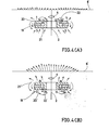
- FIGURE 4(A) shows a sectional view of a focus controller incorporating an improved means as a preferred embodiemnt of the present invention
- FIGURE 3(B) shows a sectional view of the other focus controller without incorporating any improved means.
- Symbols N and S respectively denote the north and south poles.
- the focus controller incorporating an improved means related to the present invention provides magnetic space 22 available s for the focussing operation in an area close to the optical disc. This construction minimizes leakage magnetism that otherwise adversely affects the recording media 8' of the optical disc.
- leakage magnetism will significantly affect the surface of the recording media 8' of the optical disc if the magnetic space 22' for the focussing operation is provided in an area remote from the optical disc as shown in FIGURE 3(B).
- Length of each arrow in FIGURES 3(A) and 3(B) denotes the intensity of the leakage magnetism at the respective position, while the direction of the leakage magnetism is shown in the arrowed direction.
- FIGURE 5(A) shows a sectional view of the tracking controller incorporating an improved means as a preferred embodiment of- the present invention
- FIGURES 5(B) and 5(C) show sectional views of the other tracking controller without incorporating any improved means.
- the tracking controller incorporating an improved means related to the present invention provides the permanent magnet 13 available for the tracking operation in the center position of the closed magnetic circuit. This construction minimizes leakage magnetism that otherwise adversely affects the recording media 8' of the optical disc.
- the leakage magnetism becomes large as the gap of the tracking magnetic space becomes large.
- the gap of the tracking magnetic space is made as narrow as possible.
- the objective lens must be movable in two dimensions, namely, up/down and left/right. If both of the tracking control magnetic circuit and the focus control magnetic circuit are supported by the stationary holder, the tracking coil must be movable in the two dimensions within the tracking magnetic space. This requires a wide magnetic space.
- the tracking magnetic circuit is supported by the movable intermediate holder 11.
- the tracking drive coil 17 is required to move only in the left/right direction within the tracking magnetic space 16. This will effectively minimize the gap of the tracking magnetic space 16, and the leakage magnetism.
- the focusing and/or tracking means can be applied to any head positioning device for a recording disc, the head being used for recording, playing back or erasing information or for performing any combination of these functions.
Abstract
Description
- The present invention relates to an optical focus position control device of an optical disc apparatus that records, plays back, and erases a variety of information by irradiating optical beams such as the laser beams onto a recording media. The present invention relates, more particularly, to an optical focus position control device in an opto-magnetic disc apparatus which records, plays back, and erases a variety of information by irradiating optical beams such as the laser beams onto a recording medium including a magnetic film.
- Conventionally, any of the existing optical discs easily causes its surface to vibrate during rotation, and as'a result, recording tracks on the disc are obliged to displace themselves in the direction of the optical axis of the incident laser beams that irradiate the disc surface. Also, being adversely affected by any deviation between the center position of the disc and the motor shaft that drives the disc, recording tracks of such a disc are then obliged to displace themselves in the direction of the disc radius (hereinafter called the radial direction). To prevent the recording tracks from any displacement, a device is provided so that the laser beams focus position can be correctly followed up within the optical head mechanism to enable the incident laser beam spot to correctly match the recording tracks of a disc. Such a device is called the optical focus position control in the following description.
- Using any of the existing optical disc apparatus such as the one that only plays back information without containing any magnetic film recording media, or the other one that can record any additional information, in order to fine adjust the focus position of the incident laser beams (hereinafter called the focus controller) to deal with the disc displacement in the direction of the optical axis of the incident laser beams, a device that can vary the position of the objective lens by means of the electromagnetism is well known by now. On the other hand, to fine adjust the focus position of the incident laser beams ( hereinafter called the tracking controller) to deal with the disc displacement in the radial direction, a variety of mechanism that can fine adjust the focus position of the incident laser beams via the rotary mirror that reflects the incident laser beams against any optimum direction have been introduced. The above- mentioned tracking control is not practical because the incident laser beams innevitably incline from the parpendi- cular direction of the disc.
- Accordingly, a new proposal has been introduced quite recently, which provides a mechanism capable of jointly performing both the focus and tracking controls mentioned above, by varying the position of the objective lens via the electromagnetic force. Basically, said mechanism comprises a coil that can be moved integrally with an objective lens and a stationary permanent magnet, thus causing the objective lens to be displaced by the current flowing through said coil.
- However, this mechanism provides the following problem.
- For Example, using a mechanism incorporating an objective lens-mirror cylinder which is supported by rubber material whose one end is secured to a stationary holder, while said objective lens-mirror cylinder can be driven by electromagnetic force existing between the coil secured to said objective lens-mirror cylinder and the magnetic circuit secured to said stationary cylinder. Since said rubber-elastic material supports the objective lens-mirror cylinder, it cannot fully resist the tilting force of the objective lens-mirror cylinder, and as a result, any accidental force may be generated when the drive force generated by said electromagnetic force cannot be applied to the gravity center of the objective lens-mirror cylinder, thus causing said cylinder to eventually generate a rotary movement. This will cause the optical axis of beams to tilt against the center axis of the objective lens, and so either the off-axis astigmation or coma aberration will adversely affect the disc tracks containing information, causing beams to poorly focus on them, and as a result, quality of the recorded information will be degraded significantly.
- Furthermore, if such an already known mechanism capable of jointly performing both the focus and tracking controls by varying the position of the objective lens via the electromagnetic force is actually applied to an optical disc apparatus, it will easily create problems described below.
- Since the proposed mechanism uses magnetism generated by a permanent magnet, a leakage magnetism or flux will be generated in portions peripheral to the disc. Nevertheless, since the disc uses the magnetic film for the recording media, if such a leakage mechanism adversely affects said magnetic film, the following problems will arise.
- (1) When the laser beams are irradiated onto an optical magnetic disc to cause temperature to rise, and simultaneously an information is recorded on said disc via an external magnetism, if a leakage magnetism out from said optical focus position control affects the disc, then the quality of the recorded information will be degraded significantly.
- (2) When playing back the recorded information via the magnetic-optical effect by irradiating laser beams onto the optical magnetic disc, any leakage flux from said optical focus position control may adversely affect the disc, thus causing the recorded information to be easily erased.
- In the light of these potential disadvantages, if an optical disc apparatus is used, it is quite necessary to completely prevent even the slightest leakage flux out of the optical focus position control from seriously affecting the optical disc. In addition, there are still further problems to solve.
- Accordingly, an object of the present invention is to provide an improved mechanism for the optical focus position control device by minimizing any adverse effect of the leakage magnetism against the optical disc.
- Another object of the present invention is to securely achieve a mechanism that stably drives the objective lens in dual directions, i.e., either in the vertical (up/down) or horizontal (left/right) direction without causing the objective lens to incline by using an optical focus position controller capable of controlling both the tracking and focussing of an optical disc apparatus.
- Still another object of the present invention is to stabilize the tracking and focussing movement of the objective lens by improving the damping characteristics of the drive and support mechanism.
- Other objects and further scope of applicability of the present invention will become apparent from the detailed description given hereinafter. It should be understood, however, that the detailed description and specific examples, while indicating preferred embodiments of the invention, are given by way of illustration only, since 1 various changes and modifications within the spirit and scope of the invention will become apparent to those skilled in the art from this detailed description.
- To achieve the above objects, pursuant to an embodiment of the present invention, a tracking control device for moving an objective lens-mirror cylinder in the radial direction, and a focus control device for moving the tracking control device in the direction of the optical axis of the incident laser beams are disposed in a stationary housing. The tracking control device includes a movable intermediate supporting unit. The objective lens-mirror cylinder is supported by the movable intermediate supporting unit via parallel springs which are movable only in the radial direction. The tracking control device further includes an electromagnetic drive unit for shifting the objective lens-mirror cylinder in the radial direction. The focus control device includes an electromagnetic drive unit for shifting the movable intermediate supporting unit in the direction of the optical axis.
- The present invention will be better understood from the detailed description given hereinbelow and the accompanying drawings which are given by way of illustration only, and thus are not limitative of the present invention and wherein:
- FIGURE I is a schematic block diagram of an optical disc apparatus;
- FIGURE 2 is a sectional view of an embodiment of an optical focus position control system of the present invention included in the optical disc apparatus of FIGURE 1;
- FIGURE 3 is a plan view of parallel springs included in the optical focus position control system of FIGURE 2;
- FIGURES 4(A) and 4(B) are sectional views for explaining an operational mode of a focus control unit included in the optical focus position control system of FIGURE 2; and
- FIGURES 5(A), 5(B), and 5(C) are sectional views for explaining an operational mode of a tracking control unit included in the optical focus position control system of FIGURE 2.
- Figure 1 shows a simplified block diagram of an optical disc apparatus as a preferred embodiment of the present infention. In Figure 1,
symbol 1 denotes a laser beam source that emitslaser beams 2.Symbol 3 denotes a mirror, and symbol 4 denotes an objective lens that causes thelaser beams 2 to be focussed onto the recording media surface of a disc.Symbol 5 denotes an optical focus position control device that causes the optical focus position to be accurately followed onto the tracks of the recording media of a disc by driving an objective lens 4 either in the vertical (up/down) or horizontal (left/right) direction.Symbol 6 denotes an optical head that contains all the optical devices mentioned above.Symbol 7 denotes a recording/erasing coil that provides that surface of the disc recording media with magnetism while either recording or erasing any information.Symbol 8 denotes an optical disc incorporating a disc recording media 8', and symbol 9 denotes motor that drives said optical disc to rotate. - The focus control to be performed by the optical focus
position control device 5, i.e., a fine adjustment of the incident laser beam focus position against the disc displacement made in the direction of the incident laser beam axis can be achieved by causing the objective lens 4 to move in the direction of the thickness of saidoptical disc 8. On the other hand, the tracking control to be performed by said optical focusposition control device 5; i.e., a fine adjustment of the incidental laser beam focus position in dealing with the disc displacement in the radial direction can be performed by causing the objective lens 4 to move in the radial direction of theoptical disc 8. - FIGURE 2 shows a detailed construction of the optical focus
position control system 5. First, the tracking control device will be described. An objective lens-mirror cylinder 10 supports the objective lens 4. The lens-mirror cylinder 10 is supported by a movableintermediate support member 11 viaparallel springs 12 so that the lens-mirror cylinder 10 is movable in the radial (left/right), tracking direction with respect to theintermediate support member 11. A trackingpermanent magnet 13, atracking yoke plate 14 amd atracking yoke 15 are secured to theintermediate support member 11, and form, in combination, a closed magnetic circuit. A trackingmagnetic space 16 is provided between thetracking yoke plate 14 and thetracking yoke 15. Atracking drive coil 17 is secured to the lens-mirror cylinder 10 across the trackingmagnetic space 16. When the tracking control current is fed to thetracking drive coil 17, magnetism will be generated in thetracking drive coil 17, and as a result, due to a combined effect with the other magnetism generated by the trackingpermanent magnet 13, all thetracking drive coil 17, the lens-mirror cylinder 10, the objective lens 4, and acounter balance 18 are displaced in the radial direction. Thecounter balance 18 is secured to the bottom of the lens-mirror cylinder 10 so that the tracking drive force is applied to the center of the gravity of the tracking movable elements. - The focus control device will be described below. A focussing
permanent magnet 19, afocussing yoke plate 20, and afocussing yoke 21 form, in combination, a closed magnetic circuit. These elements are securely installed to astationary holder 25 which fully supports the optical focus position control device. A focussingmagnetic space 22 is formed between thefocussing yoke plate 20 and thefocussing yoke 21. Afocus drive coil 23 is secured to the movableintermediate support member 11 across the focussingmagnetic space 22. The mobableintermediate support member 11 is supported by thestationary holder 25 viaparallel springs 24 so that the movableintermediate support member 11 is movable in the vertical direction, namely, in the direction of the incident laser beam axis with respect to thestationary holder 25. When the focus control current is fed to thefocus drive coil 23, magnetism is generated in thefocus drive coil 23, and as a result, due to a combined effect with the other magnetism generated by the focussingpermanent magnet 19, the tracking control device supported by the movableintermediate support member 11 is displaced in the focus direction ( direction of the incident laser beam axis ). - Next, the movement characteristics of both the focussing and tracking controllers of the objective lens-
mirror cylinder 10 are described below. - As shown in FIGURE 2, the tracking controller is driven by the electromagnetic effect that interacts between the tracking closed magnetic circuit secured to the
intermediate support member 11 and thetracking drive coil 17 secured to the objective lens-mirror cylinder 10. Theintermediate support member 11 and the objective lens-mirror cylinder 10 are connected to each other via the elestic material that is workable only to the left and to the right by moving in the radial direction, i.e., via aparallel spring 12 that moves in the direction of the disc radius. Assuming that the weight of the units movable in the tracking direction ( the objective lens 4, the objective lens-mirror cylinder 10, and the tracking drive coil 17 ) is MT and the spring constant of theparallel spring 12 moving in the direction of the disc radius is KT, and then the objective lens-mirror cylinder 10 will have a resonance frequency fT which is represented by a formula
mirror cylinder 10 moves to the left and to the right. When the tracking drive force FT is generated by the interacting electromagnetic force mentioned above with a frequency denoted by fHz, the movement phase delay caused by the displacement XT of the objective lens-mirror cylinder 10 in the tracking direction is 0° through 90° when 0<f<fT, or 90° through 180° when fT<f, or near 180° when fT«f. When the tracking drive force FT is generated, the delay in the movement phase caused by the displacement XT of the objective lens-mirror cylinder 10 moving to the tracking target position YT should remain below 180° throughout the frequency bands of the tracking control signal. When a phase advancing compensation circuit is used to advance the phase of the tracking drive signal FT, the phase delay is properly maintained below 180°. This ensures a stable tracking control. - As shown in FIGURE 2, the focussing controller is driven by the electromagnetic effect that interacts between the focussing closed magnetic circuit secured to the
stationary holder 25 and the focussingdrive coil 23 secured to theintermediate support member 11. Theintermediate support member 11 and thestationary holder 25 are connected to each other via theparallel spring 24 which is workable only in the vertical direction by moving in the direction of focussing. Assuming that the weight of the movable part in the direction of focussing including the tracking control device is MF, whereas the spring constant of theparallel spring 24 moving in the direction of focussing is KF, and then the objective lens-mirror cylinder 10 will be provided with a resonance frequency which is represented by a formula
interim holder 11 and the objective lens-mirror cylinder 10 are connected to each other via theparallel spring 12 moving in the tracking direction. When the focus driving force is applied to the device, theaprallel spring 12 slightly moves in the vertical direction due to its elasticity. Thus, assuming that the spring constant in the focus-direction of theparallel spring 12 is KT', the objective lens-mirror cylinder 10 will have a resonance frequency ( hereinafter called the secondary resonance frequency ) represented as
- As described above, whenever the objective lens-
mirror cylinder 10 moves upward and downward, both the primany and secondary resonance frequencies exist. Note that the spring constant KT' in the vertical direction of theparallel spring 12 is considerably large, or KT'»KF. This means that the secondary resonance frequency f'F is significantly higher than the primany resonance frequency fF, the relationship of which is denoted by f'F>fF. As soon as a driving force FF for the focussing operation is given by the interacting electromagnetic force, the movement phase delay in the displacement XF caused by the objective lens-mirror 10 in the focussing direction can be represented to be 0° through 90° when 0< f <fF, where f (Hz) represents a frequency, whereas such a delay in the movement phase can be represent to be 90° through 270° when fF<f<f'F, and it will be 270° through 360° when f'F<f. When the focussing drive force FF is generated, the delay in the movement phase caused by the displacement XF of the objective lens-mirror cylinder 10 moving to the focussing target position YF should remain below 180° throughout the frequency bands of the focussing control signal. As described earlier, even if the phase advancing compensation circuit is used to advance the phase of the focussing drive signal FF, since there is a certain limit for advancing the phase amount, the phase cannot be compensated for in order that it can exceed 180° significantly. To properly compensate for the phase delay, the second resonance frequency fF should be set at an optimum level higher than the frequency band of the focussing control signal. Although frequency bands available for the focussing control signal are variable N according to uses, generally, an optical disc apparatus uses 1 through 4KHz of the frequency bands. As a result, it was made clear that the secondary resonance frequency f'F should be set at a level above 7KHz. - Means for designing a construction that fully satisfies the above conditions are described below.
- As described above, the secondary resonance frequency f'F can be determined by the spring constant KT' of the tracking
parallel spring 12 when it moves in the focussing direction and by the weight MT of the moving parts in the tracking direction. The secondary resonance frequency f'F becomes large as the spring constant KT' becomes large and as the weight MT becomes small. Nevertheless, since there is a certain limit in the means for decreasing the weight MT of the objective lens 4 and the lens-mirror cylinder 10, the weight MT of the parts moving in the tracking direction cannot be decreased significantly. (Normally, the weight MT is designed in a range from 0.5 to 10 grams.) The inventors followed up trials for increasing the spring constant KT' of the trackingparallel spring 12 during its movement in the vertical direction. The spring constant KT' was found to be KT'/KT = (XT/yT)2when the trackingparallel spring 12 had a length XT in the focus direction YT. As a result, it is clear that the spring constant KT' in the vertical direction (up/down) can be increased,by expanding the length XT and decreasing the thickness YT of theparallel spring 12. In the light of the relationship denoted by

parallel spring 12 should be designed so that it can be provided with 20 through 50 micron meter of the thickness YT and an actual length taht is 100 up to 500 times the thickness YT. If the trackingparallel spring 12 can be correctly designed in accordance with the findings described above, the delay in the movement phase caused by the displacement XF of the objective lens 4 against the focussing target position can be decreased below 180° within the frequency bands available for the focussing control signal. It is important that the phase advancing compensation circuit be used for correctly compensating for the movement phase. - According to the results of the trials followed up by the inventors, very stable focussing and tarcking controls were actually achieved by using a tracking
parallel spring 12 made from beryllium-copper alloy having 30 through 50 micron meters of the thickness. - As discussed above in the sections (I) and (II), there are N two kinds of the resonance frequencies fF and fT when the tracking control device and the focus control device are operated. If the damping characteristics in the directions of focussing and tracking control remain negligible, the resonance multiple factor in the resonance frequencies fF and fT will grow, thus causing any interference vibration to easily occur during either the focussing or tracking control operation. Also, when a certain frequency above the resonance frequency level is fed, the phase in responding to the displacement of the movable parts will be extremely delayed to a point very close to 180°, which will result in an extremely unstable optical focus position control operation. To prevent this and ensure satisfactory amount of the damping characteristics, the present invention effectively provides the following means.
- The primary improvement includes a latexed damping member painted on the focussing parallel spring and/or the tracking parallel spring. (The plate rubber attached to the metal spring by an adhesive is not suited for the device, because the spring constant becomes high due to the adhesive.) To make up the damping material, viscose-elastic materials such as silicon rubber, butyl rubber, silicon-butyl rubber, and acrylic-ethylene rubber, foaming synthetic resin such as foamed polyurethane, and viscose fluid such as silicon grease, can be made available.
- FIGURE 3 shows a plane view of the focussing
parallel spring 24. The focussingparallel spring 24 has a structure that connects two concentric circles, where two flat sheet springs, each being connected to four arms at the edges, are provided in the upper and lower positions. Theparallel spring 24 moving in the direction of focus causes theintermediate holder 11 to move only in the vertical direction with respect to the stationary holder 25.(see FIGURE 2.) Dampingmaterial 26 is bonded to the portion C of the surface of the focussingparallel spring 24, where the largest amount of the relative displacement exists, thus resulting in greater damping characteristics in the direction of focus. To make up the dampingmaterial 26, viscose-elastic materials such as silicon-rubber, butyl rubber, silicon-butyl rubber, and acrylic-ethylene rubber, and foaming synthetic resin such as foamed polyurethane, can be made available. - The third improvement is to form the focussing parallel spring and/or the tracking parallel spring with a vibration-proof alloy such as manganese-copper alloy, ferro-aluminum alloy, nickel-titanium alloy, and magnesium alloy.
- The structures of (III-a), (III-b) and (III-c) can be effectively combined with each other to significantly enhance the damping characteristics.
- (IV) Improvement in connection with applying the present optical focus position controlling device to an opto-magnetic disc apparatus
- The present invention provides a variety of means for effectively preventing the optical focus position control device from causing its leakage mangetism to adversely affect the recording media 8' of the
optical disc 8. Such effective means are described below. - FIGURE 4(A) shows a sectional view of a focus controller incorporating an improved means as a preferred embodiemnt of the present invention, whereas FIGURE 3(B) shows a sectional view of the other focus controller without incorporating any improved means. Symbols N and S respectively denote the north and south poles. As shown in FUGURE 3(A), the focus controller incorporating an improved means related to the present invention provides
magnetic space 22 available s for the focussing operation in an area close to the optical disc. This construction minimizes leakage magnetism that otherwise adversely affects the recording media 8' of the optical disc. In other words, leakage magnetism will significantly affect the surface of the recording media 8' of the optical disc if the magnetic space 22' for the focussing operation is provided in an area remote from the optical disc as shown in FIGURE 3(B). Length of each arrow in FIGURES 3(A) and 3(B) denotes the intensity of the leakage magnetism at the respective position, while the direction of the leakage magnetism is shown in the arrowed direction. - FIGURE 5(A) shows a sectional view of the tracking controller incorporating an improved means as a preferred embodiment of- the present invention, whereas FIGURES 5(B) and 5(C) show sectional views of the other tracking controller without incorporating any improved means. The tracking controller incorporating an improved means related to the present invention provides the
permanent magnet 13 available for the tracking operation in the center position of the closed magnetic circuit. This construction minimizes leakage magnetism that otherwise adversely affects the recording media 8' of the optical disc. In other words, in such a construction where the permanent magnet 13' available for the tracking operation is provided encircling the closed magnetic circuit as shown in FIGURE 5(B), or in such a construction where the open magnetic circuit faces the optical disc as shown in FIGURE 5(C), if the magnitude of magnetism that functions in themagnetic space 16' or 16" is designed to be equal to saidmagnetic space 16 of FIGURE 5(A) available for the tracking operation, leakage magnetism will significantly affect the surface of the recording media 8' of the optical disc. - When the magnetic field in the tracking magnetic space is selected at a fixed value, the leakage magnetism becomes large as the gap of the tracking magnetic space becomes large. Thus, it is preferable that the gap of the tracking magnetic space is made as narrow as possible. The objective lens must be movable in two dimensions, namely, up/down and left/right. If both of the tracking control magnetic circuit and the focus control magnetic circuit are supported by the stationary holder, the tracking coil must be movable in the two dimensions within the tracking magnetic space. This requires a wide magnetic space.
- In accordance with the present invention, the tracking magnetic circuit is supported by the movable
intermediate holder 11. By this construction, thetracking drive coil 17 is required to move only in the left/right direction within the trackingmagnetic space 16. This will effectively minimize the gap of the trackingmagnetic space 16, and the leakage magnetism. - The embodiments of the invention thus described with reference to the accompanying drawings will obviously be suggestive of derivations and modifications. For example, the focusing and/or tracking means can be applied to any head positioning device for a recording disc, the head being used for recording, playing back or erasing information or for performing any combination of these functions.
- There are thus described above novel features which the skilled man will appreciate give rise to advantages. These are each independent aspects of the invention to be covered by the present application, irrespective of whether they are included within the scope of the following claims.
Claims (17)

Applications Claiming Priority (4)
| Application Number | Priority Date | Filing Date | Title |
|---|---|---|---|
| JP6877183A JPS59193552A (en) | 1983-04-18 | 1983-04-18 | Controller for light focusing position |
| JP68771/83 | 1983-04-18 | ||
| JP59053842A JPH0756696B2 (en) | 1984-03-19 | 1984-03-19 | Light focusing position controller |
| JP53842/84 | 1984-03-19 |
Publications (3)
| Publication Number | Publication Date |
|---|---|
| EP0122816A2 true EP0122816A2 (en) | 1984-10-24 |
| EP0122816A3 EP0122816A3 (en) | 1985-11-27 |
| EP0122816B1 EP0122816B1 (en) | 1990-07-18 |
Family
ID=26394564
Family Applications (1)
| Application Number | Title | Priority Date | Filing Date |
|---|---|---|---|
| EP84302661A Expired EP0122816B1 (en) | 1983-04-18 | 1984-04-18 | Optical focus position control in an optical memory system |
Country Status (3)
| Country | Link |
|---|---|
| US (1) | US4658390A (en) |
| EP (1) | EP0122816B1 (en) |
| DE (1) | DE3482725D1 (en) |
Cited By (2)
| Publication number | Priority date | Publication date | Assignee | Title |
|---|---|---|---|---|
| GB2233107A (en) * | 1989-06-07 | 1991-01-02 | Unisys Corp | "lens shuttle mechanism for microfilmer camera". |
| EP0604159A2 (en) * | 1992-12-21 | 1994-06-29 | Canon Kabushiki Kaisha | Magneto-optical recording apparatus |
Families Citing this family (15)
| Publication number | Priority date | Publication date | Assignee | Title |
|---|---|---|---|---|
| US4745589A (en) * | 1984-10-04 | 1988-05-17 | Seiko Epson Kabushiki Kaisha | Objective lens actuator having movements restricting control means for an optical head |
| EP0215498B1 (en) * | 1985-08-14 | 1992-01-02 | Philips Patentverwaltung GmbH | Optical-scanning unit |
| KR900006182B1 (en) * | 1986-03-04 | 1990-08-25 | 상요 덴기 가부시기가이샤 | Electric mechanical tranducer |
| KR900006183B1 (en) * | 1986-03-04 | 1990-08-25 | 상요 덴기 가부시기가이샤 | Optical pick up apparatus |
| US4782476A (en) * | 1986-06-24 | 1988-11-01 | Sharp Kabushiki Kaisha | Objective lens-driving unit |
| JPH01177416U (en) * | 1988-06-07 | 1989-12-19 | ||
| JPH02187932A (en) * | 1989-01-12 | 1990-07-24 | Olympus Optical Co Ltd | Light beam moving device |
| US5138497A (en) * | 1991-03-15 | 1992-08-11 | Eastman Kodak Company | High speed focusing lens assembly |
| US5563871A (en) * | 1993-11-09 | 1996-10-08 | International Business Machines Corporation. | Rotary actuator with a magnetic bias bearing configuration for rotating an optical element in an optical data storage system |
| KR100329918B1 (en) * | 1998-10-28 | 2002-09-04 | 삼성전자 주식회사 | Pickup Actuator |
| US6829708B1 (en) * | 1999-03-27 | 2004-12-07 | Microsoft Corporation | Specifying security for an element by assigning a scaled value representative of the relative security thereof |
| US7583289B2 (en) * | 2003-01-02 | 2009-09-01 | Ge Security, Inc. | Optical block assembly |
| US7113351B2 (en) * | 2003-01-02 | 2006-09-26 | Covi Technologies, Inc. | Systems and methods for actuating lens assemblies |
| TWI298805B (en) * | 2005-02-15 | 2008-07-11 | Sony Corp | Lens unit and imaging apparatus |
| JP4589909B2 (en) * | 2006-10-27 | 2010-12-01 | 株式会社日立メディアエレクトロニクス | Objective lens drive |
Citations (8)
| Publication number | Priority date | Publication date | Assignee | Title |
|---|---|---|---|---|
| JPS5485736A (en) * | 1977-12-21 | 1979-07-07 | Olympus Optical Co Ltd | Damping device of objective lens apparatus |
| FR2425782A1 (en) * | 1978-05-10 | 1979-12-07 | Olympus Optical Co | Optical data read=out unit - has objective supported on carrier and projecting light spot from light source onto recording medium |
| JPS5542368A (en) * | 1978-09-19 | 1980-03-25 | Mitsubishi Electric Corp | Pickup controller |
| WO1980001016A1 (en) * | 1978-11-01 | 1980-05-15 | Hitachi Ltd | Magneto-optical anisotropy detecting device |
| JPS57113431A (en) * | 1981-01-07 | 1982-07-14 | Olympus Optical Co Ltd | Objective-lens driver |
| JPS57198550A (en) * | 1981-05-29 | 1982-12-06 | Sony Corp | Supporting device for optical system |
| EP0115666A2 (en) * | 1983-01-25 | 1984-08-15 | Sharp Kabushiki Kaisha | Optical focus position control in optical disc apparatus |
| JPS59152503A (en) * | 1983-02-19 | 1984-08-31 | Canon Inc | Optical pickup device |
Family Cites Families (12)
| Publication number | Priority date | Publication date | Assignee | Title |
|---|---|---|---|---|
| US4100576A (en) * | 1976-04-28 | 1978-07-11 | Zenith Radio Corporation | Electromagnetic optical beam controller having an eddy current damper for arresting mechanical resonance |
| US4302830A (en) * | 1978-05-10 | 1981-11-24 | Olympus Optical Company Ltd. | Optical information reading-out apparatus |
| GB2052829B (en) * | 1979-04-27 | 1983-01-12 | Olympus Optical Co | Apparatus for driving objective lens in tracking direction |
| GB2060927B (en) * | 1979-07-24 | 1984-02-01 | Universal Pioneer Corp | Signal reading device for optical discs |
| FR2469853B1 (en) * | 1979-11-12 | 1986-09-12 | Nippon Telegraph & Telephone | PICK-UP FOR USE IN A DEVICE FOR PLAYING VIDEO AND / OR AUDIO INFORMATION |
| JPS5720927A (en) * | 1980-07-09 | 1982-02-03 | Olympus Optical Co Ltd | Objective lens driver |
| GB2088646B (en) * | 1980-10-24 | 1984-09-12 | Sony Corp | Pick-up assemblies for disc players |
| JPS57103131A (en) * | 1980-12-18 | 1982-06-26 | Sony Corp | Biaxial driver |
| US4482986A (en) * | 1981-01-30 | 1984-11-13 | Sony Corporation | Objective lens mount for optical disc player |
| JPS57147148A (en) * | 1981-03-05 | 1982-09-10 | Olympus Optical Co Ltd | Information reproducer with magnetooptic system |
| JPS57181436A (en) * | 1981-05-01 | 1982-11-08 | Toshiba Corp | Optical disc device |
| JPS5812145A (en) * | 1981-07-13 | 1983-01-24 | Matsushita Electric Ind Co Ltd | Driving device of objective lens |
-
1984
- 1984-04-16 US US06/600,374 patent/US4658390A/en not_active Expired - Lifetime
- 1984-04-18 EP EP84302661A patent/EP0122816B1/en not_active Expired
- 1984-04-18 DE DE8484302661T patent/DE3482725D1/en not_active Expired - Lifetime
Patent Citations (8)
| Publication number | Priority date | Publication date | Assignee | Title |
|---|---|---|---|---|
| JPS5485736A (en) * | 1977-12-21 | 1979-07-07 | Olympus Optical Co Ltd | Damping device of objective lens apparatus |
| FR2425782A1 (en) * | 1978-05-10 | 1979-12-07 | Olympus Optical Co | Optical data read=out unit - has objective supported on carrier and projecting light spot from light source onto recording medium |
| JPS5542368A (en) * | 1978-09-19 | 1980-03-25 | Mitsubishi Electric Corp | Pickup controller |
| WO1980001016A1 (en) * | 1978-11-01 | 1980-05-15 | Hitachi Ltd | Magneto-optical anisotropy detecting device |
| JPS57113431A (en) * | 1981-01-07 | 1982-07-14 | Olympus Optical Co Ltd | Objective-lens driver |
| JPS57198550A (en) * | 1981-05-29 | 1982-12-06 | Sony Corp | Supporting device for optical system |
| EP0115666A2 (en) * | 1983-01-25 | 1984-08-15 | Sharp Kabushiki Kaisha | Optical focus position control in optical disc apparatus |
| JPS59152503A (en) * | 1983-02-19 | 1984-08-31 | Canon Inc | Optical pickup device |
Non-Patent Citations (6)
| Title |
|---|
| JAPANESE JOURNAL OF APPLIED PHYSICS, vol. 19, no. 12, pages 4731-4734, December 1980, Tokyo, JP; N. IMAMURA et al.: "Experimental study on magneto-optical disk exerciser with the laser diode and amorphous magnetic thin films" * |
| PATENT ABSTRACTS OF JAPAN, vol. 3, no. 107 (E-136), page 147 e 136, 8th September 1979; & JP-A-54 085 736 (OLYMPUS KOGAKU KOGYO K.K.) 07-07-1979 * |
| PATENT ABSTRACTS OF JAPAN, vol. 4, no. 78 (P-14) [560], page 46 P 14, 6th June 1980; & JP-A-55 042 368 (MITSUBISHI DENKI K.K.) 25-03-1980 * |
| PATENT ABSTRACTS OF JAPAN, vol. 6, no. 206 (P-149) [1084], 19th October 1982; & JP-A-57 113 431 (OLYMPUS KOGAKU KOGYO K.K.) 14-07-1982 * |
| PATENT ABSTRACTS OF JAPAN, vol. 7, no. 51 (P-179) [1196], 26th February 1983; & JP-A-57 198 550 (SONY K.K.) 06-12-1982 * |
| PATENT ABSTRACTS OF JAPAN, vol. 9, no. 2 (P-325) [1725], 8th January 1985; & JP-A-59 152 503 (CANON K.K.) 31-08-1984 * |
Cited By (6)
| Publication number | Priority date | Publication date | Assignee | Title |
|---|---|---|---|---|
| GB2233107A (en) * | 1989-06-07 | 1991-01-02 | Unisys Corp | "lens shuttle mechanism for microfilmer camera". |
| US5014085A (en) * | 1989-06-07 | 1991-05-07 | Unisys Corporation | Lens shuttle mechanism for microfilm camera |
| GB2233107B (en) * | 1989-06-07 | 1993-09-01 | Unisys Corp | Lens shuttle mechanism for microfilmer camera |
| EP0604159A2 (en) * | 1992-12-21 | 1994-06-29 | Canon Kabushiki Kaisha | Magneto-optical recording apparatus |
| EP0604159A3 (en) * | 1992-12-21 | 1994-12-14 | Canon Kk | Magneto-optical recording apparatus. |
| US5563853A (en) * | 1992-12-21 | 1996-10-08 | Canon Kabushiki Kaisha | Magneto-optical recording apparatus that compensates for magnetic fields leaking from an objective lens actuator and a linear motor |
Also Published As
| Publication number | Publication date |
|---|---|
| EP0122816B1 (en) | 1990-07-18 |
| EP0122816A3 (en) | 1985-11-27 |
| US4658390A (en) | 1987-04-14 |
| DE3482725D1 (en) | 1990-08-23 |
Similar Documents
| Publication | Publication Date | Title |
|---|---|---|
| US4660190A (en) | Optical focus position control in optical disc apparatus | |
| US4658390A (en) | Optical focus position control in an optical memory system | |
| JP3154141B2 (en) | Buffer device and recording and / or reproducing device for disk-shaped recording medium using buffer device | |
| JPS6339980B2 (en) | ||
| EP0115666A2 (en) | Optical focus position control in optical disc apparatus | |
| KR100362215B1 (en) | Lens shifter (without yoke bridge) | |
| KR100695460B1 (en) | Optical scanning device and optical player with parallel-controlled actuators | |
| CA1219073A (en) | Optical focus position control in an optical memory system | |
| EP0314200B1 (en) | Optical focus position control device | |
| EP0318772B1 (en) | Optical focus position control device | |
| JP3510947B2 (en) | Optical pickup device | |
| JPH10255290A (en) | Objective lens for optical pickup | |
| JPH0756696B2 (en) | Light focusing position controller | |
| JPS6243256B2 (en) | ||
| JP2706357B2 (en) | Optical information recording / reproducing device | |
| JPS6284437A (en) | Drive device for objective lens | |
| JP2621200B2 (en) | Objective lens actuator | |
| JPH03154235A (en) | Actuator | |
| JP2602004B2 (en) | Objective lens drive | |
| JP2720557B2 (en) | Objective lens drive | |
| JPS59195336A (en) | Controller for light condensing position | |
| JPH0438725A (en) | Optical head | |
| JPS6063739A (en) | Two-dimensionally driving device of objective lens | |
| JPS6284438A (en) | Drive device for objective lens | |
| Katoh et al. | Servo technology for three-beam overwritable magneto-optical disk drive |
Legal Events
| Date | Code | Title | Description |
|---|---|---|---|
| PUAI | Public reference made under article 153(3) epc to a published international application that has entered the european phase |
Free format text: ORIGINAL CODE: 0009012 |
|
| AK | Designated contracting states |
Designated state(s): DE FR GB IT |
|
| PUAL | Search report despatched |
Free format text: ORIGINAL CODE: 0009013 |
|
| AK | Designated contracting states |
Designated state(s): DE FR GB IT |
|
| 17P | Request for examination filed |
Effective date: 19860505 |
|
| 17Q | First examination report despatched |
Effective date: 19871109 |
|
| ITF | It: translation for a ep patent filed |
Owner name: DR. ING. A. RACHELI & C. |
|
| GRAA | (expected) grant |
Free format text: ORIGINAL CODE: 0009210 |
|
| AK | Designated contracting states |
Kind code of ref document: B1 Designated state(s): DE FR GB IT |
|
| REF | Corresponds to: |
Ref document number: 3482725 Country of ref document: DE Date of ref document: 19900823 |
|
| ET | Fr: translation filed | ||
| ITTA | It: last paid annual fee | ||
| PLBE | No opposition filed within time limit |
Free format text: ORIGINAL CODE: 0009261 |
|
| STAA | Information on the status of an ep patent application or granted ep patent |
Free format text: STATUS: NO OPPOSITION FILED WITHIN TIME LIMIT |
|
| 26N | No opposition filed | ||
| REG | Reference to a national code |
Ref country code: GB Ref legal event code: IF02 |
|
| PGFP | Annual fee paid to national office [announced via postgrant information from national office to epo] |
Ref country code: FR Payment date: 20030408 Year of fee payment: 20 |
|
| PGFP | Annual fee paid to national office [announced via postgrant information from national office to epo] |
Ref country code: GB Payment date: 20030416 Year of fee payment: 20 |
|
| PGFP | Annual fee paid to national office [announced via postgrant information from national office to epo] |
Ref country code: DE Payment date: 20030502 Year of fee payment: 20 |
|
| PG25 | Lapsed in a contracting state [announced via postgrant information from national office to epo] |
Ref country code: GB Free format text: LAPSE BECAUSE OF EXPIRATION OF PROTECTION Effective date: 20040417 |
|
| REG | Reference to a national code |
Ref country code: GB Ref legal event code: PE20 |