EP0121840A2 - Position determination device for an object within a field of view - Google Patents
Position determination device for an object within a field of view Download PDFInfo
- Publication number
- EP0121840A2 EP0121840A2 EP84103195A EP84103195A EP0121840A2 EP 0121840 A2 EP0121840 A2 EP 0121840A2 EP 84103195 A EP84103195 A EP 84103195A EP 84103195 A EP84103195 A EP 84103195A EP 0121840 A2 EP0121840 A2 EP 0121840A2
- Authority
- EP
- European Patent Office
- Prior art keywords
- field
- view
- arrangement according
- radiation
- radiation source
- Prior art date
- Legal status (The legal status is an assumption and is not a legal conclusion. Google has not performed a legal analysis and makes no representation as to the accuracy of the status listed.)
- Withdrawn
Links
- 230000005855 radiation Effects 0.000 claims abstract description 74
- 230000015654 memory Effects 0.000 description 10
- 238000010586 diagram Methods 0.000 description 6
- 230000003287 optical effect Effects 0.000 description 3
- 239000003990 capacitor Substances 0.000 description 2
- 230000006870 function Effects 0.000 description 2
- 230000000630 rising effect Effects 0.000 description 2
- 239000002390 adhesive tape Substances 0.000 description 1
- 230000006378 damage Effects 0.000 description 1
- 238000011161 development Methods 0.000 description 1
- 230000018109 developmental process Effects 0.000 description 1
- 239000011521 glass Substances 0.000 description 1
- 238000003384 imaging method Methods 0.000 description 1
- 238000000034 method Methods 0.000 description 1
- 238000012544 monitoring process Methods 0.000 description 1
Images


Classifications
-
- G—PHYSICS
- G06—COMPUTING; CALCULATING OR COUNTING
- G06F—ELECTRIC DIGITAL DATA PROCESSING
- G06F3/00—Input arrangements for transferring data to be processed into a form capable of being handled by the computer; Output arrangements for transferring data from processing unit to output unit, e.g. interface arrangements
- G06F3/01—Input arrangements or combined input and output arrangements for interaction between user and computer
- G06F3/03—Arrangements for converting the position or the displacement of a member into a coded form
- G06F3/041—Digitisers, e.g. for touch screens or touch pads, characterised by the transducing means
- G06F3/042—Digitisers, e.g. for touch screens or touch pads, characterised by the transducing means by opto-electronic means
- G06F3/0428—Digitisers, e.g. for touch screens or touch pads, characterised by the transducing means by opto-electronic means by sensing at the edges of the touch surface the interruption of optical paths, e.g. an illumination plane, parallel to the touch surface which may be virtual
-
- G—PHYSICS
- G06—COMPUTING; CALCULATING OR COUNTING
- G06F—ELECTRIC DIGITAL DATA PROCESSING
- G06F3/00—Input arrangements for transferring data to be processed into a form capable of being handled by the computer; Output arrangements for transferring data from processing unit to output unit, e.g. interface arrangements
- G06F3/01—Input arrangements or combined input and output arrangements for interaction between user and computer
- G06F3/03—Arrangements for converting the position or the displacement of a member into a coded form
- G06F3/041—Digitisers, e.g. for touch screens or touch pads, characterised by the transducing means
- G06F3/042—Digitisers, e.g. for touch screens or touch pads, characterised by the transducing means by opto-electronic means
- G06F3/0421—Digitisers, e.g. for touch screens or touch pads, characterised by the transducing means by opto-electronic means by interrupting or reflecting a light beam, e.g. optical touch-screen
Definitions
- the invention relates to an arrangement for determining the position of an object within a field of view.
- Such an article may be a finger or pencil, m eem a vision device is pointed at a particular point of a screen, for example, and its presence and location to be determined.
- the arrangement can also be used to determine the presence of a person within a confined area, such as a room.
- Known devices for determining the position of an object within a field of view feel the interruption of radiation, e.g. of light, through an opaque object, e.g. the part of a human body.
- Such a device uses radiation transmitters that emit radiation across the field of view, parallel to the surface of the field of view, and radiation receivers that detect the radiation that has spread over the field of view and the presence and location of an interruption of this radiation (e.g. through an object).
- a known device for determining the position of a small object, for example a human finger or a pencil, in an XY plane uses an arrangement of light sources which lie along a side in the X direction of a rectangular field of view and a corresponding arrangement of light receivers are provided on the opposite side of the field of view extending in the X direction.
- Corresponding is an arrangement of light sources along the side of the field of view running in the Y direction and an arrangement of Light receivers are provided on the opposite side of the field of view, which also extends in the Y direction.
- light transmitters or light receivers are arranged along the circumference of the field of view. Examples of such devices are disclosed in U.S. Patents 3,478,220, 3,764,813, 3,775,560 and 3,860,754.
- the known devices have a number of disadvantages.
- the spatial resolution of the device is determined by the number, size and distance of the individual light sources and light receivers. In known devices, it is therefore possible for a human finger to lie between two adjacent light receivers and thus not to be caught by the parallel rays of light.
- the known device has a large number of active elements, e.g. Light sources and light receivers, which are very expensive and in most cases have to be assembled very precisely by human labor.
- the large number of light sources and light receivers enforce the complex and elaborate circuitry arrangements required to operate the device.
- This device comprises a rectangular frame with four sides and an open interior for the work surface or the field of view. Lamps are arranged on the frame which emit light into the interior of the frame from three sides.
- a couple of light receivers are arranged on the frame in two corners, at the opposite ends of the fourth side of the frame. Furthermore, openings are provided in the two frame corners, to be precise between the light receivers and the frame interior, in order to fix matching light areas for the light receivers increase.
- Each light receiver receives the light from a special light field inside the frame and detects the interruption of the light at any location in this field.
- the known device according to US Pat. No. 4,144,449 has the advantage over the devices already described above which have paired light sources and light receivers that the number of components is considerably reduced while the resolution of the device is increased.
- the known device requires a relatively large frame and a larger number of light sources which are arranged on at least three sides of the frame. Therefore, the device is very large and bulky and is therefore not suitable to be subsequently arranged on an existing screen.
- the object on which the invention is based is to provide an arrangement for determining the position of an object within a field of view, which is simple in structure and can easily be inserted subsequently into an existing field of vision.
- the arrangement should be usable both for small fields of view, such as computer screens, and for relatively large fields of view, such as a room in a building.
- the arrangement according to the invention thus generates, with the aid of at least one point-shaped radiation source, which can be embodied, for example, as an LED, radiation which illuminates the field of view and is reflected back from the back-reflecting surface to the point-shaped light source.
- the reflected radiation is received and evaluated by a radiation receiver arranged adjacent to the punctiform radiation source, unless the radiation is interrupted by an object in the field of view.
- the reflective surface can e.g. consist of a retroreflective tape that is commercially available for use as roadside reflectors and the like.
- the surface of this tape is formed from a layer of thin transparent balls, e.g. of glass.
- the tape is relatively inexpensive and can be easily attached to the sides or walls of the field of view.
- the field of view can therefore be relatively small, e.g. in the case of a computer screen or relatively large, such as in the case of a building room.
- the arrangement may include electronic circuitry connected to the radiation receivers in order to. Determine coordinates of the object, which is arranged within the field of view.
- the field of view may be rectangular and the electrical circuitry may then generate signals that are proportional to the X and Y coordinates of the object within the field of view.
- the radiation used in the arrangement is preferably light; however, if ambient light could interfere with the operation of the arrangement, radiation of invisible frequencies such as infrared or microwave radiation can be used.
- two radiation receivers can be arranged at adjacent corners of the rectangular field of view.
- three or more radiation receivers can be provided on the circumference of the field of view.
- the electrical circuit for determining the coordinates of an object arranged within the field of view can position the object in two dimensions (X, Y coordinates) or in three dimensions (X, Y, Z coordinates). specify. Specifying three dimensions has the advantage that the object that enters the field of view in the Z direction (for example, a finger moves against a computer screen) is only recognized if its Z coordinate exceeds a threshold.
- the electrical circuit can be implemented in such a way that it only indicates the position of objects that exceed a certain size. In this way 2 n noise and uninteresting small objects can be suppressed.
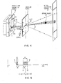
- FIG. 1 shows a computer screen that has a field of view 10 that is surrounded by a frame 12.
- the inner surface of the frame 12, which is essentially vertical to the visible surface of the screen 10, is provided with a reflective layer 14.
- Layer 14 provides a back-reflecting surface that extends around the circumference of the field of view.
- the back-reflecting surface is a surface that reflects radiation generated by a radiation source back to the radiation source.
- the reflective layer 14 can be attached directly to the frame 12 or it can be arranged on an adhesive tape which is attached to the inner surface of the frame. Corresponding back-reflecting tapes are already commercially available.
- the device also contains two essentially point-shaped radiation sources. These radiation sources are not shown in FIG. 1. However, they are shown in FIG. 2, in which their position in relation to the field of view 10 is shown. 2 that a first radiation source 16 is arranged at one corner of the field of view 10 and a second radiation source 18 is arranged at another, second corner of a side surface 20.
- the side surface 20 of the field of view does not have to be provided with a back-reflecting layer, as shown in FIG. 1.
- the point-shaped radiation sources illuminate the entire field of view with radiation, for example with light.
- the radiation propagates in a direction parallel to the plane of the field of view 10.
- the back reflection rende area on the circumference of the field of view reflects the radiation back to the corresponding radiation source, as shown in Fig. 2 by the arrows in the field of view.
- a beam 22 extends from the radiation source 16, for example an LED, to the side of the field of view and returns to the radiation source.
- the layer 14 consists of a plurality of small, transparent balls 24, which act as tiny lenses and mirrors, which reflect the incident rays and ensure that the exit angle is the same as the entry angle.
- Fig. 1 shows how the device determines the presence and location of an object 26 within the perimeter of the frame 12. It is assumed that radiation, eg light, is generated by point-shaped radiation sources, eg LEDs, at the lower left and at the lower right corner of the field of view (as shown in FIG. 2); this light crosses the field of view and is reflected back to a slit 28 in the lower left corner and to a slit 30 in the lower right corner of the field of view 10.
- Columns 28 and 30 serve as optical diaphragms to separate individual beams on sensitive surfaces 32 and 34 to map dynamic RA MB 36 and 38 modules. These are queried by an electrical circuit 40, which emits output signals that are proportional to the X, Y coordinates of the object 26.
- FIG. 4 shows an imaging system in which the radiation consists of light generated by an LED
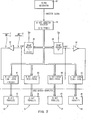
- FIG. 5 shows a block diagram of the control unit 40.
- light generated by the LED 16 is reflected back to this source by the reflecting surface 14.
- the light traverses the gap 28 and strikes the surface 32 of the dynamic RAM faceplate 36.
- the light discharges a photosensitive capacitor on surface 32, creating a logic zero in memory at each location that receives light. If an opaque object, such as a pencil or human finger, is inserted into the field of view, a shadow is cast on the faceplate and the capacitors within the shaded area keep their charge.
- the faceplate thus generates a logical 1 at the output for each memory cell within the shaded area.
- the dynamic RAM faceplate can e.g. consist of 256 cells (0 to 255) arranged in a line along the transducer surface.
- X represents the position of the shadow of an opaque object 26 on the transducer surface 32 in dynamic RAM; then X is proportional to the angle that the opaque object makes through the gap with the zeroth cell.
- the opposite sides of the shadow fall at positions X1 and X2 (0 ⁇ X1 ⁇ X2 ⁇ 255), the mean X or the center of the shadow is (X1 + X2) / 2.
- the X, Y position of the object 26 can be determined with the aid of the so-called "triangulation".
- two angles 91 and g 2 are measured and the X, Y coordinates from the values of these two angles calculated using the distance D between the two measuring points.
- FIG. 5 shows an exemplary embodiment of the electrical control unit 40 for determining the X, Y coordinates from the information which is output by the dynamic RAM modules.
- This circuit uses the principle of reading the table to find the coordinates.
- the circuit includes a clock generator 42 that sends clock pulses to a frequency divider (flip-flop) 44 and an address counter 46.
- the output of the address counter 46 is connected to the two dynamic RAM modules 36 and 38 and further to two 8 bit counters 48 and 50.
- the clock pulses from the clock generator 42 are further transmitted to two 8-bit counters 52 and 54, which generate output numbers A1 and A2.
- the outputs of the counters 52 and 54 are each connected to 8-bit comparators 56 and 58, which compare the output numbers A1 and A2 with numbers B1 and B2.
- the numbers B1 and B2 can be supplied to the control unit 40 from toggle switches or from a computer.
- the clock pulses from the clock generator 42 and from the frequency divider 44 are fed to two multiplexers 60 and 62.
- the multiplexers are connected to the dynamic RAM modules 36 and 38 with their inputs and to the counters 48 and 50 with their outputs.
- the outputs of the dynamic RAM modules 36 and 38 are also connected to the counters 52 and 54, respectively.
- the contents of the 8 bit counters 48 and 50 are each transferred into 8 bit catch registers 64 and 66 when a transfer pulse is emitted from the 8 bit address counter 46.
- the contents of the two latches 64 and 66 are used to address two 64K x 8 ROMs 68 and 70.
- Counters 52 and 54 and comparators 56 and 58 serve to eliminate shadows that do not exceed a minimum width.
- the numbers A1 and A2 which represent the widths of the shadows that are fed to the respective RAM chips 36 and 38, are compared with fixed numbers B1 and B2, which e.g. are in a range from 30 to 50 (picture element width) of objects which are to be recognizable by the RAM modules 36 and 38. If the shadows have a width (in numbers of the memory cells) that is smaller than this value (B1 or B2) then they are ignored.
- the ROM memories 68 and 70 contain the respective coordinates X and Y, which correspond to the respective values in the catch registers 64 and 66, respectively.
- the coordinate values can best be determined by manual calibration of the system. For this purpose, an object is placed in the field of view at known coordinates X and Y. These coordinates are then stored in the respective ROM memories 68 and 70 at the address generated by the system. With the help of a curve recorder, the calibration can also be carried out automatically for all addresses.
- Fig. 6 shows how shadows that are too narrow are hidden.
- the control unit determines a first shadow 72 with a width A1 that is smaller than the minimum width B1. This shadow is ignored.
- the system finds a second shadow 74 with a width A1 that is greater than the minimum width B1.
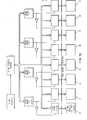
- FIG. 7 shows another embodiment of the control unit 40.
- the X and Y coordinates are determined with the aid of a microprocessor which works with appropriate software.
- the lower address (X1) of the shadow is transferred from a dynamic RAM module 36 to a first 8 bit parallel input / output port 76.
- the higher address (X2) of the shadow is transmitted to a second input / output port 78.
- the lower address (X1) of a shadow which is generated by the other dynamic RAM module 38, is transmitted to the input / output port 80 and, accordingly, the higher address (X2) of the shadow is transmitted to the input / output port 82.
- the lower and higher addresses are selected by triggering the 8 bit latches 84, 86, 88 and 90 with the rising edges of the pulses.
- Inverters 92 are used to generate rising edge pulses that change from lower to higher potential when transitioning from a darkened area to a light area.
- FIG. 8 shows a further exemplary embodiment in which an arrangement of 128 ⁇ 256 cells in a dynamic RAM module is used to define a second, the Z dimension of the shadow, which is formed by an opaque object.
- the aperture plate 94 contains a small lens 96.
- the infrared radiation which is generated by the source 98 (LED) is reflected by the back-reflecting surface 100 through the lens 96 to the converter surface 102 of the dynamic RAM module 104.
- An opaque 'article 106 such as a finger, forming a shadow 108 on the surface 102.
- the Extenz and the position of this shadow which is illustrated schematically in Fig. 9, is determined by addressing the cells of the RAM block 104th
- the control circuit for addressing the cells of the RAM module 104 is constructed similarly to that shown in FIG. 7.
- a 16-bit address counter can be used instead of the 8-bit address counter 46 to address the 128 x 256 cells of each RAM chip.
- the microcomputer memory must also be correspondingly larger in order to store the additional, third coordinates.
- FIG. 10 shows a control unit which is suitable for addressing 4 dynamic RAM modules in parallel operation.
- the positions of the shadow corners (cells X1 and X2) are stored repeatedly in 8 bit catch registers and are offered to the respective 8 bit parallel input / output ports of the microprocessor.
Abstract
Zur Feststellung der Lage eines Gegenstandes innerhalb eines Sichtfeldes, z.B. eines Bildschirms, sind punktförmige Strahlungsquellen entfernt voneinander am Umfang des Sichtfeldes (10) angeordnet. Weiterhin ist der Umfang des Sichtfeldes (10) mit einer zurückreflektierenden Fläche (14) versehen. Die zurückreflektierende Fläche (14) reflektiert die Strahlung, die von den punktförmigen Strahlungsquellen ausgehen, zu diesen Strahlungsquellen zurück. Strahlungsempfänger (36, 38) sind jeweils benachbart zu den Strahlungsquellen angeordnet, so daß sie in der von der zurückreflektierenden Fläche (14) zurückreflektierten Strahlung liegen. Ist ein Gegenstand (26) im Sichtfeld (10) angeordnet, dann wird dieser Gegenstand auf den Strahlungsempfängern (36, 38) abgebildet. Aus der Lage dieser Abbildung auf den Strahlungsempfängern (36, 38) können die Koordinaten des Gegenstandes (26) innerhalb des Sichtfeldes (10) berechnet werden.To determine the position of an object within a field of view, e.g. of a screen, point-shaped radiation sources are arranged at a distance from one another on the circumference of the field of view (10). Furthermore, the circumference of the field of view (10) is provided with a reflecting surface (14). The back-reflecting surface (14) reflects the radiation emanating from the point-shaped radiation sources back to these radiation sources. Radiation receivers (36, 38) are each arranged adjacent to the radiation sources so that they lie in the radiation reflected back by the back-reflecting surface (14). If an object (26) is arranged in the field of view (10), then this object is imaged on the radiation receivers (36, 38). The coordinates of the object (26) within the field of view (10) can be calculated from the position of this image on the radiation receivers (36, 38).
Description
Die Erfindung bezieht sich auf eine Anordnung zur Feststellung der Lage eines Gegenstandes innerhalb eines Sichtfeldes. Ein solcher Gegenstand kann ein Finger oder Bleistift sein,meem auf eine bestimmte Stelle eines Bildschirmes z.B. eines Sichtgerätes gedeutet wird und dessen Vorhandensein und Lage festgestellt werden soll. Die Anordnung kann auch verwendet werden, um das Vorhandensein einer Person innerhalb eines umgrenzten Bereiches, z.B. eines Zimmers, festzustellen.The invention relates to an arrangement for determining the position of an object within a field of view. Such an article may be a finger or pencil, m eem a vision device is pointed at a particular point of a screen, for example, and its presence and location to be determined. The arrangement can also be used to determine the presence of a person within a confined area, such as a room.
Bekannte Vorrichtungen zur Feststellung der Lage eines Gegenstandes innerhalb eines Sichtfeldes tasten die Unterbrechung einer Strahlung, z.B. von Licht, durch einen undurchsichtigen Gegenstand, z.B. den Teil eines menschlichen Körpers, ab. Eine solche Vorrichtung verwendet Strahlungssender, die Strahlung über das Sichtfeld, und zwar parallel zu der Oberfläche des Sichtfeldes, ausstrahlen und Strahlungsempfänger, die die Strahlung, die sich über das Siohtfeld ausgebreitet hat, erfassen und das Vorhandensein und die Lage einer Unterbrechung dieser Strahlung (z.B. durch einen Gegenstand) erkennen.Known devices for determining the position of an object within a field of view feel the interruption of radiation, e.g. of light, through an opaque object, e.g. the part of a human body. Such a device uses radiation transmitters that emit radiation across the field of view, parallel to the surface of the field of view, and radiation receivers that detect the radiation that has spread over the field of view and the presence and location of an interruption of this radiation (e.g. through an object).
Eine bekannte Vorrichtung zur Feststellung der Lage eines kleinen Gegenstandes, z.B. eines menschlichen Fingers oder eines Bleistiftes, in einer X-Y Ebene verwendet eine Anordnung von Lichtquellen, die entlang einer in X-Richtung liegenden Seite eines rechteckförmigen Sichtfeldes liegen und eine entsprechende Anordnung von Lichtempfänger, die auf der gegenüberliegenden in X-Richtung verlaufenden Seite des Sichtfeldes vorgesehen sind. Entsprechend ist eine Anordnung von Lichtquellen entlang der in Y-Richtung verlaufenden Seite des Sichtfeldes und eine Anordnung von Lichtempfängern auf der gegenüberliegenden ebenfalls in Y-Richtung verlaufenden Seite des Sichtfeldes vorgesehen. Somit sind entlang des Umfangs des Sichtfeldes jeweils Lichtsender oder Lichtempfänger angeordnet. Beispiele für solche Vorrichtungen sind in den US-Patentschriften 3 478 220, 3 764 813, 3 775 560 und 3 860 754 offenbart.A known device for determining the position of a small object, for example a human finger or a pencil, in an XY plane uses an arrangement of light sources which lie along a side in the X direction of a rectangular field of view and a corresponding arrangement of light receivers are provided on the opposite side of the field of view extending in the X direction. Corresponding is an arrangement of light sources along the side of the field of view running in the Y direction and an arrangement of Light receivers are provided on the opposite side of the field of view, which also extends in the Y direction. Thus, light transmitters or light receivers are arranged along the circumference of the field of view. Examples of such devices are disclosed in U.S. Patents 3,478,220, 3,764,813, 3,775,560 and 3,860,754.
Die bekannten Vorrichtungen haben eine Reihe von Nachteilen. Erstens wird die räumliche Auflösung der Vorrichtung durch die Anzahl, die Größe und den Abstand der einzelnen Lichtquellen und Lichtempfänger festgelegt. Bei bekannten Vorrichtungen ist es daher möglich, daß ein menschlicher Finger zwischen zwei benachbarten Lichtempfängern liegt und somit von den parallel verlaufenden Strahlen des Lichtes nicht erfaßt wird. Zweitens weist die bekannte Vorrichtung eine große Anzahl von aktiven Elementen, z.B. Lichtquellen und Lichtempfängern, auf, die sehr teuer sind und in den meisten Fällen durch menschliche Arbeitskraft sehr genau montiert werden müssen. Drittens erzwingt die große Anzahl von Lichtquellen und Lichtempfängern komplexe und aufwendige Anordnungen von Schaltkreisen, die zum Betrieb der Vorrichtung erforderlich sind.The known devices have a number of disadvantages. First, the spatial resolution of the device is determined by the number, size and distance of the individual light sources and light receivers. In known devices, it is therefore possible for a human finger to lie between two adjacent light receivers and thus not to be caught by the parallel rays of light. Second, the known device has a large number of active elements, e.g. Light sources and light receivers, which are very expensive and in most cases have to be assembled very precisely by human labor. Third, the large number of light sources and light receivers enforce the complex and elaborate circuitry arrangements required to operate the device.
Eine andere Art einer Vorrichtung zur Feststellung der Lage eines Gegenstandes ist aus der US-Patentschrift 4 144 449 bekannt. Diese Vorrichtung umfaßt einen rechteckigen Rahmen mit vier Seiten und einen offenen Innenraum für die Arbeitsfläche oder das Sichtfeld. Auf dem Rahmen sind Lampen angeordnet, die von drei Seiten aus Licht in den Innenraum des Rahmens emittieren. Ein paar Lichtempfänger sind am Rahmen in zwei Ecken und zwar an den entgegengesetzt liegenden Enden der vierten Seite des Rahmens angeordnet. Weiterhin sind Öffnungen in den zwei Rahmenecken, und zwar zwischen den Lichtempfängern und dem Rahmeninneren vorgesehen, um übereinstimmende Lichtbereiche für die Lichtempfänger festzulegen. Jeder Lichtempfänger empfängt das Licht von einem besonderen Lichtfeld innerhalb des Rahmeninneren und stellt die Unterbrechung des Lichtes an irgendeinen Ort dieses Feldes fest. Die bekannte Vorrichtung nach dem US-Patent 4 144 449 hat den Vorteil gegenüber dem bereits oben beschriebenen Vorrichtungen, die paarweise angeordnete Lichtquellen und Lichtempfänger aufweisen, daß die Anzahl der Komponenten erheblich reduziert wird, während die Auflösung der Vorrichtung vergrößert wird.Another type of device for determining the position of an object is known from US Pat. No. 4,144,449. This device comprises a rectangular frame with four sides and an open interior for the work surface or the field of view. Lamps are arranged on the frame which emit light into the interior of the frame from three sides. A couple of light receivers are arranged on the frame in two corners, at the opposite ends of the fourth side of the frame. Furthermore, openings are provided in the two frame corners, to be precise between the light receivers and the frame interior, in order to fix matching light areas for the light receivers increase. Each light receiver receives the light from a special light field inside the frame and detects the interruption of the light at any location in this field. The known device according to US Pat. No. 4,144,449 has the advantage over the devices already described above which have paired light sources and light receivers that the number of components is considerably reduced while the resolution of the device is increased.
Trotzdem erfordert die bekannte Vorrichtung einen verhältnismäßig großen Rahmen und eine größere Anzahl von Lichtquellen, die zumindest auf drei Seiten des Rahmens angeordnet sind. Deshalb ist die Vorrichtung sehr groß und unhandlich und ist daher nicht geeignet, nachträglich an einem bereits vorhandenen Bildschirm angeordnet zu werden.Nevertheless, the known device requires a relatively large frame and a larger number of light sources which are arranged on at least three sides of the frame. Therefore, the device is very large and bulky and is therefore not suitable to be subsequently arranged on an existing screen.
Weiterhin ist die Anwendbarkeit der bekannten Vorrichtung auf verhältnismäßig kleine Lichtfelder, z.B. Computerbildschirme, begrenzt. Sie ist nicht geeignet, um die Lage von Gegenständen innerhalb eines großen Sichtfeldes, z.B. eines Raumes in einem Gebäude, festzustellen. Es ist zwar theoretisch denkbar, eine lineare Lichtquelle entlang den Mauern eines Raumes anzuordnen, derartige Lichtquellen wären aber extrem teuer, zufälligen Zerstörungen ausgesetzt und wären ästhetisch nicht ansprechend.Furthermore, the applicability of the known device to relatively small light fields, e.g. Computer screens, limited. It is not suitable for determining the position of objects within a large field of view, e.g. of a room in a building. Although it is theoretically conceivable to arrange a linear light source along the walls of a room, such light sources would be extremely expensive, subject to accidental destruction and would not be aesthetically pleasing.
Es wäre somit wünschenswert, eine Vorrichtung entsprechend der US-Patentschrift 4 144 449 zur Verfügung zu haben, mit der sowohl die Lage von Gegenständen in großen als auch in kleinen Sichtfeldern feststellbar ist. Die Vorrichtung wäre dann z.B. anwendbar zur überwachung von Räumen. Sie könnte aber auch in Verbindung mit mechanischen automatischen Einrichtungen verwendet werden. Dann könnte die Vorrichtung das Abschalten der Einrichtung bewirken, wenn z.B. ein Mensch den Arbeitsbereich der mechanischen Einrichtung betritt.It would therefore be desirable to have a device according to US Pat. No. 4,144,449 available, with which the position of objects in large as well as in small fields of view can be determined. The device would then be applicable, for example, for monitoring rooms. However, it could also be used in connection with mechanical automatic devices. Then the device could cause the device to turn off, for example, a human enters the working area of the mechanical device.
Die der Erfindung zugrundeliegende Aufgabe besteht darin, eine Anordnung zur Feststellung der Lage eines Gegenstandes innerhalb eines Sichtfeldes anzugeben, die einfach im Aufbau ist und leicht nachträglich in ein bestehendes Sichtfeld eingefügt werden kann. Dabei soll die Anordnung sowohl für kleine Sichtfelder, wie Computerbildschirme, als auch für verhältnismäßig große Sichtfelder, wie ein Raum in einem Gebäude, verwendbar sein.The object on which the invention is based is to provide an arrangement for determining the position of an object within a field of view, which is simple in structure and can easily be inserted subsequently into an existing field of vision. The arrangement should be usable both for small fields of view, such as computer screens, and for relatively large fields of view, such as a room in a building.
Diese Aufgabe wird durch folgende Merkmale gelöst:
- Eine erste, im wesentlichen punktförmige Strahlungsquelle ist an einem ersten Ort auf dem Umfang des Sichtfeldes angeordnet, um das Sichtfeld auszuleuchten,
- eine zurückreflektierende Fläche ist am Umfang angeordnet, um die von der Strahlungsquelle auftreffende Strahlung zur Strahlungsquelle zurückzureflektieren,
- eine erste Einrichtung ist auf dem Umkreis benachbart zur ersten Strahlungsquelle so angeordnet, daß sie im Bereich der von der zurückreflektierenden Fläche reflektierten Strahlung liegt,
- die erste Einrichtung tastet das Sichtfeld in einer ersten Richtung ab und speichert beim Vorhandensein eines Gegenstandes im Sichtfeld ein dessen Lage in der ersten Richtung entsprechenden ersten Wert ab.
- A first, essentially point-shaped radiation source is arranged at a first location on the circumference of the field of view in order to illuminate the field of view,
- a back-reflecting surface is arranged on the circumference in order to reflect the radiation incident from the radiation source back to the radiation source,
- a first device is arranged on the circumference adjacent to the first radiation source in such a way that it lies in the region of the radiation reflected by the back-reflecting surface,
- the first device scans the field of vision in a first direction and, when an object is present in the field of vision, stores a first value corresponding to its position in the first direction.
Die erfindungsgemäße Anordnung erzeugt somit mit Hilfe von mindestens einer punktförmigen Strahlungsquelle, die z.B. als LED ausgeführt sein kann, Strahlung, die das Sichtfeld ausleuchtet und von der zurückreflektierenden Fläche zu der punktförmigen Lichtquelle zurückreflektiert wird. Die reflektierte Strahlung wird von einem benachbart zu der punktförmigen Strahlungsquelle angeordneten Strahlungsempfänger empfangen und ausgewertet, es sei denn, dieStrahlund wird von einem Gegenstand im Sichtfeld unterbrochen.The arrangement according to the invention thus generates, with the aid of at least one point-shaped radiation source, which can be embodied, for example, as an LED, radiation which illuminates the field of view and is reflected back from the back-reflecting surface to the point-shaped light source. The reflected radiation is received and evaluated by a radiation receiver arranged adjacent to the punctiform radiation source, unless the radiation is interrupted by an object in the field of view.
Die zurückreflektierende Fläche kann z.B. aus einem zurückreflektierenden Band bestehen, das im Handel zur Verwendung als Straßenrandreflektoren und ähnlichem verfügbar ist. Die Oberfläche dieses Bandes ist aus einer Schicht aus dünnen transparenten Kugeln gebildet, z.B. aus Glas. Das Band ist verhältnismäßig billig und kann auf einfache Weise an den Seiten oder Wänden des Sichtfeldes befestigt werden. Das Sichtfeld kann deshalb verhältnismäßig klein sein, wie z.B. im Fall eines Computerbildschirmes oder verhältnismäßig groß, wie im Fall eines Gebäuderaumes.The reflective surface can e.g. consist of a retroreflective tape that is commercially available for use as roadside reflectors and the like. The surface of this tape is formed from a layer of thin transparent balls, e.g. of glass. The tape is relatively inexpensive and can be easily attached to the sides or walls of the field of view. The field of view can therefore be relatively small, e.g. in the case of a computer screen or relatively large, such as in the case of a building room.
Die Anordnung kann einen elektronischen Schaltkreis umfassen, der mit den Strahlungsempfängern verbunden ist, um die. Koordinaten des Gegenstandes, der innerhalb des Sichtfeldes angeordnet ist, zu bestimmen. Z.B. kann das Sichtfeld rechteckig sein und der elektrische Schaltkreis kann dann Signale erzeugen, die proportional sind der X- und Y-Koordinate des Gegenstandes innerhalb des Sichtfeldes.The arrangement may include electronic circuitry connected to the radiation receivers in order to. Determine coordinates of the object, which is arranged within the field of view. E.g. the field of view may be rectangular and the electrical circuitry may then generate signals that are proportional to the X and Y coordinates of the object within the field of view.
Die bei der Anordnung verwendete Strahlung ist vorzugsweise Licht; wenn jedoch Umgebungslicht die Arbeitsweise der Anordnung stören könnte, kann Strahlung nicht sichtbarer Frequenzen wie Infrarot- oder Mikrowellenstrahlung verwendet werden.The radiation used in the arrangement is preferably light; however, if ambient light could interfere with the operation of the arrangement, radiation of invisible frequencies such as infrared or microwave radiation can be used.
Vorzugsweise können zwei Strahlungsempfänger an benachbarten Ecken des rechteckigen Sichtfeldes angeordnet sein. Soll jedoch eine verbesserte Auflösung erreicht werden, können drei oder mehr Strahlungsempfänger am Umfang des Sichtfeldes vorgesehen werden.Preferably, two radiation receivers can be arranged at adjacent corners of the rectangular field of view. However, if an improved resolution is to be achieved, three or more radiation receivers can be provided on the circumference of the field of view.
Der elektrische Schaltkreis zur Bestimmung der Koordinaten eines innerhalb des Sichtfeldes angeordneten Gegenstandes kann die Lage des Gegenstandes in zwei Dimensionen (X, Y-Koordinaten) oder in drei Dimensionen (X, Y, Z-Koordinaten) angeben. Die Angabe von drei Dimensionen hat den Vorteil, daß der Gegenstand, der in das Sichtfeld in Z-Richtung eintritt (z.B. ein Finger sigtgegen einen Computerbildschirm) nur erkannt wird, wenn seine Z-Koordinate eine Schwelle überschreitet.The electrical circuit for determining the coordinates of an object arranged within the field of view can position the object in two dimensions (X, Y coordinates) or in three dimensions (X, Y, Z coordinates). specify. Specifying three dimensions has the advantage that the object that enters the field of view in the Z direction (for example, a finger moves against a computer screen) is only recognized if its Z coordinate exceeds a threshold.
Weiterhin kann der elektrische Schaltkreis derart realisiert sein, daß er die Lage nur von solchen Gegenständen anzeigt, die eine bestimmte Größe überschreiten. Auf diese Weise kön- n2n Rauschen und uninteressante kleine Gegenstände unterdrückt werden.Furthermore, the electrical circuit can be implemented in such a way that it only indicates the position of objects that exceed a certain size. In this way 2 n noise and uninteresting small objects can be suppressed.
Weiterbildungen der Erfindung ergeben sich aus den Unteransprüchen.Further developments of the invention result from the subclaims.
Anhand von Ausführungsbeispielen, die in den Figuren dargestellt sind, wird die Erfindung weiter erläutert. Es zeigen
- Fig. 1 einen Grundriß der Anordnung,
- Fig. 2 eine schematische Darstellung der Arbeitsweise der Anordnung,
- Fig. 3 eine schematische Darstellung der Arbeitsweise der zurückreflektierenden Fläche,
- Fig. 4 eine perspektivische Ansicht des optischen Systems, das in der Anordnung verwendet wird,
- Fig. 5 ein Blockschaltbild des elektrischen Schaltkreises, der in der Anordnung verwendet wird,
- Fig. 6 ein Diagramm, das die Filterfunktion des Schaltkreises nach Fig. 5 erläutert,
- Fig. 7 ein Blockschaltbild einer zweiten Ausführungsform des elektrischen Schaltkreises,
- Fig. 8 eine perspektivische Ansicht einer weiteren Ausführungsform des optischen Systems, das in Fig. 1 verwendbar ist,
- Fig. 9 ein zwei Koordinaten-Diagramm, das die Funktion des dynamischen RAM Bildbausteins im Ausführungsbeispiel der Fig. 8 zeigt,
- Fig. 10 ein Blockschaltbild einer dritten Ausführung des elektronischen Schaltkreises, der in der Anordnung verwendbar ist.
- 1 is a plan view of the arrangement,
- 2 is a schematic representation of the operation of the arrangement,
- 3 shows a schematic representation of the mode of operation of the reflecting surface,
- 4 is a perspective view of the optical system used in the arrangement.
- 5 is a block diagram of the electrical circuit used in the arrangement.
- 6 is a diagram explaining the filter function of the circuit of FIG. 5,
- 7 is a block diagram of a second embodiment of the electrical circuit,
- 8 is a perspective view of another embodiment of the optical system that can be used in FIG. 1,
- 9 is a two coordinate diagram showing the function of the dynamic RAM faceplate in the embodiment of FIG. 8,
- Fig. 10 is a block diagram of a third embodiment of the electronic circuit which can be used in the arrangement.
Fig. 1 zeigt einen Computerbildschirm, der ein Sichtfeld 10 aufweist, das von einem Rahmen 12 umgeben ist. Die innere Oberfläche des Rahmens 12, die im wesentlichen vertikal zur Sichtfläche des Bildschirms 10 verläuft, ist mit einer zurückreflektierenden Schicht 14 versehen. Die Schicht 14 sieht eine zurückreflektierende Fläche vor, die am Umfang des Sichtfeldes verläuft. Die zurückreflektierende Fläche ist eine Fläche, die von einer Strahlungsquelle erzeugte Strahlung zur Strahlungsquelle zurückreflektiert.FIG. 1 shows a computer screen that has a field of
Die zurückreflektierende Schicht 14 kann direkt am Rahmen 12 angebracht sein oder sie kann auf einem aufklebbaren Band angeordnet sein, das an der inneren Oberfläche des Rahmens befestigt wird. Entsprechende zurückreflektierende Bänder sind fertig im Handel erhältlich.The
Die Vorrichtung enthält weiterhin zwei im wesentlichen punktförmige Strahlungsquellen. Diese Strahlungsquellen sind in Fig. 1 nicht dargestellt. Sie sind aber in Fig. 2 gezeigt, in der ihre Lage in Beziehung zum Sichtfeld 10 dargestellt ist. Aus Fig. 2 ergibt sich, daß eine erste Strahlungsquelle-16 an einer Ecke des Sichtfeldes 10 und eine zweite Strahlungsquelle 18 an einer anderen, zweiten Ecke einer Seitenfläche 20 angeordnet ist. Die Seitenfläche 20 des Sichtfeldes muß nicht mit einer zurückreflektierenden Schicht, wie in Fig. 1 gezeigt, versehen sein.The device also contains two essentially point-shaped radiation sources. These radiation sources are not shown in FIG. 1. However, they are shown in FIG. 2, in which their position in relation to the field of
Nach Fig. 2 beleuchten die punktenförmigen Strahlungsquellen das gesamte Sichtfeld mit Strahlung, z.B. mit Licht. Die Strahlung breitet sich dabei in einer Richtung parallel zu der Ebene des Sichtfeldes 10 aus. Die zurückreflektierende Fläche am Umfang des Sichtfeldes reflektiert die Strahlung zurück zur entsprechenden Strahlungsquelle, wie es in der Fig. 2 durch die Pfeile im Sichtfeld gezeigt ist. Zum Beispiel erstreckt sich ein Strahl 22 von der Strahlungsquelle 16, z.B. einer LED, zu der Seite des Sichtfeldes und kehrt zu der Strahlungsquelle zurück.According to FIG. 2, the point-shaped radiation sources illuminate the entire field of view with radiation, for example with light. The radiation propagates in a direction parallel to the plane of the field of
Fig. 3 zeigt, wie die Strahlen 22 zu ihren Strahlungsquellen durch die zurückreflektierende Schicht 14 reflektiert werden. Die Schicht 14 besteht dabei aus einer Mehrzahl von kleinen, transparenten Kugeln 24, die als winzige Linsen und Spiegeln wirken, die die auftreffenden Strahlen reflektieren und sicherstellen, daß der Ausgangswinkel der gleiche ist wie der Eingangswinkel.3 shows how the
Fig. 1 zeigt, wie die Vorrichtung das Vorhandensein und die Lage eines Gegenstandes 26 innerhalb der Umgrenzung des Rahmens 12 feststellt. Es wird angenommen, daß Strahlung, z.B. Licht, von punktförmigen Strahlungsquellen, z.B. LEDs an der unteren linken und an der unteren rechten Ecke des Sichtfeldes erzeugt wird (so wie es in der Fig. 2 dargestellt ist); dieses Licht durchquert das Sichtfeld und wird zurückreflektiert zu einem Spalt 28 in der linken unteren Ecke und zu einem Spalt 30 in der rechten unteren Ecke des Sichtfeldes 10. Die Spalten28 und 30 dienen als optische Blenden, um einzelne Strahlen auf empfindlichen Flächen 32 und 34 eines dynamischen RAM Bildbausteins 36 und 38 abzubilden. Diese werden von einem elektrischen Schaltkreis 40 abgefragt, der Ausgangssignale abgibt, die proportional sind zu den X,Y-Koordinaten des Gegenstandes 26.Fig. 1 shows how the device determines the presence and location of an
Die Arbeitsweise der Anordnung zur Feststellung der Lage eines Gegenstandes läßt sich am besten verstehen mit Hilfe der Fig. 4 und 5. Fig. 4 zeigt ein Abbildungssystem, bei dem die Strahlung aus Licht besteht, erzeugt von einem LED und Fig. 5 zeigt ein Blockschaltbild der Steuereinheit 40. Wie Fig. 4 entnommen werden kann, wird Licht, das von dem LED 16 erzeugt wird, durch die zurückreflektierende Fläche 14 zu dieser Quelle zurückreflektiert. Das Licht durchquert dabei den Spalt 28 und trifft auf der Fläche 32 des dynamischen RAM Bildbausteins 36 auf. Das Licht entlädt auf der Oberfläche 32 einen lichtempfindlichen Kondensator und erzeugt dabei eine logische Null im Speicher an jeder Speicherstelle, die Licht empfängt. Wenn ein undurchsichtiger Gegenstand, wie z.B. ein Bleistift oder ein menschlicher Finger, in das Sichtfeld eingeführt wird, dann wird ein Schatten auf den Bildbaustein geworfen und die Kondensatoren innerhalb des abgeschatteten Bereiches behalten ihre Ladung. Der Bildbaustein erzeugt so eine logische 1 am Ausgang für jede Speicherzelle innerhalb des abgeschatteten Bereiches.The mode of operation of the arrangement for determining the position of an object can best be understood with the aid of FIGS. 4 and 5. FIG. 4 shows an imaging system in which the radiation consists of light generated by an LED and FIG. 5 shows a block diagram of the
Der dynamische RAM Bildbaustein kann z.B. aus 256 Zellen (0 bis 255) bestehen, die in einer Linie entlang der Wandlerfläche angeordnet sind. Es sei angenommen, daß X die Position des Schattens eines undurchsichtigen Gegenstandes 26 auf der Wandlerfläche 32 im dynamischen RAM darstellt; dann ist X proportional zu dem Winkel, den der undurchsichtige Gegenstand durch den Spalt hindurch mit der nullten Zelle bildet. Unter der Annahme, daß die entgegengesetzten Seiten des Schattens auf Positionen X1 und X2 (0≤X1≤X2≤255) fallen, dann liegt der Mittelwert X oder das Zentrum des Schattens bei (X1 + X2)/2.The dynamic RAM faceplate can e.g. consist of 256 cells (0 to 255) arranged in a line along the transducer surface. Assume that X represents the position of the shadow of an
Wenn eine Kombination von zwei Lichtquellen und zwei dynamischen Bausteinen verwendet wird, wie dies in den Fig. 1 und 2 dargestellt ist, dann kann die X, Y Lage des Gegenstandes 26 mit Hilfe der sog. "Triangulation" bestimmt werden. In diesem Falle werden zwei Winkel 91 und g2 gemessen und die X,Y Koordinaten aus den Werten dieser zwei Winkel unter Verwendung des Abstandes D zwischen den zwei Meßpunkten berechnet.If a combination of two light sources and two dynamic components is used, as shown in FIGS. 1 and 2, the X, Y position of the
Fig. 5 zeigt ein Ausführungsbeispiel der elektrischen Steuereinheit 40 zur Bestimmung der X, Y Koordinaten aus der Information, die von den dynamischen RAM.Bausteinen abgegeben wird. Diese Schaltung verwendet das Prinzip des Tabellenlesens, um die Koordinaten aufzusuchen. Die Schaltung enthält einen Taktgenerator 42, der Taktimpulse zu einem Frequenzunterteiler (Flip Flop) 44 und einem Adressenzähler 46 sendet. Der Ausgang des Adressenzählers 46 ist mit den beiden dynamischen RAM Bausteinen 36 und 38 und weiterhin mit zwei 8 bit Zählern 48 und 50 verbunden. Die Taktimpulse vom Taktgenerator 42 werden weiterhin zu zwei 8 bit Zählern 52 und 54 übertragen, die Ausgangszahlen A1 und A2.erzeugen. Die Ausgänge der Zähler 52 und 54 sind mit 8 bit Komparatoren 56 und 58 jeweils verbunden, die die Ausgangszahlen A1 und A2 mit Zahlen B1 und B2 vergleichen. Die Zahlen B1 und B2 können der Steuereinheit 40 von Kippschaltern oder von einem Computer zugeführt werden.FIG. 5 shows an exemplary embodiment of the
Die Taktimpulse vom Taktgenerator 42 und vom Frequenzteiler 44 werden zwei Multiplexern 60 und 62 zugeführt. Die Multiplexer sind mit ihren Eingängen jeweils mit den dynamischen RAM Bausteinen 36 und 38 und mit ihren Ausgängen jeweils mit den Zählern 48 und 50 verbunden. Die Ausgänge der dynamischen RAM Bausteine 36 und 38 sind weiterhin jeweils mit den Zählern 52 und 54 verbunden.The clock pulses from the
Die Inhalt der 8 bit Zähler 48 und 50 werden jeweils in 8 bit Auffangregister 64 und 66 übertragen, wenn ein übertragimpuls von dem 8 bit Adressenzähler 46 abgegeben wird. Die Inhalte der beiden Auffangregister 64 und 66 werden verwendet, um zwei 64 K x 8 ROM 68 und 70 zu adressieren.The contents of the 8 bit counters 48 and 50 are each transferred into 8 bit catch registers 64 and 66 when a transfer pulse is emitted from the 8
Durch die Schaltung nach Fig. 5 werden die Zellen der dynamischen RAM Bausteine 36 und 38 aufeinanderfolgend adressiert. Die Ausgangssignale dieser Zellen (logisch 0 für .Zellen, die Licht erhalten haben und logisch 1 für Zellen, die kein Licht erhalten haben) werden zu den 8 bit Zählern 48 und 50' in folgender Weise übertragen:
- Jede Zelle mit einer logischen 0 wird dadurch gezählt, daß der Taktimpuls vom Eingang A des jeweiligen Multiplexers zu dem Takteingang des jeweiligen Zählers 48 oder 50 übertragen wird. Jede andere Speicherzelle mit einer
logischen 1 wird dadurch gezählt, daß der Taktimpuls halber Frequenz vom Eingang B des jeweiligen Multiplexers zu dem Takteingang des jeweiligen Zählers 48 oder 50 übertragen wird.Die Zähler 48 und 50 werdenjedes Mal auf 0 zurückgesetzt, wenn die erste Zelle (Zelle 0) des dynamischenRAM Bausteins 36 und 38 adressiert wird.Die Zähler 48 und 50 werden gestoppt, wenn an ihren Ladeeingängen Signale von den jeweiligen-Komparatoren 56 und 58 auftreten. Die Inhalte der Zähler 48 und 50 werden dann indie jeweiligen Auffangregister 64 und 66 übertragen,wenn der 8bit Adressenzähler 46 dieAdressenzahl 255 erreicht.
- Each cell with a logical 0 is counted in that the clock pulse is transmitted from input A of the respective multiplexer to the clock input of the
respective counter respective counter counters dynamic RAM module Counters respective comparators counters bit address counter 46 reaches theaddress number 255.
Die Zähler 52 und 54 und die Komparatoren 56 und 58 dienen dazu, um solche Schatten zu eliminieren, die eine Minimumbreite nicht überschreiten. Die Zahlen A1 und A2, die die Breiten der Schatten, die den jeweiligen RAM Bausteinen 36 und 38 zugeführt werden, darstellen, werden jeweils mit festgelegten Zahlen B1 und B2 verglichen, die z.B. in einem Bereich von 30 bis 50 (Bildelementbreite) von Gegenständen liegen, die durch die RAM Bausteine 36 und 38 erkennbar sein sollen. Wenn die Schatten eine Breite (in Zahlen der Speicherzellen) haben, die kleiner ist als dieser Wert (B1 oder B2) dann werden sie ignoriert.
Dementsprechend erzeugen die Zähler 48 und 50 ein Zählergebnis X, das die Position (in Bildelementen) des Zentrums des Gegenstandes darstellt. Unter der Annahme, daß X1 die niedrigere Speicherzellenadresse der einen Seite des Schattens und X2 die höhere Speicherzellenadresse der entgegengesetzten Seite des Schattens ist (Fig. 4), dann wird das Zählergebnis X nach folgender Formel festgelegt:
- X = X1 + 1/2 (X2 - X1)
Die Zähler 48 und 50 zählen zunächst die Zahlen X1 mit der ursprünglichen Taktfrequenz und zählen dann dieZahlen 1/2 (X2 - X1) mit der halben Taktfrequenz.
- X = X1 + 1/2 (X2 - X1)
- The
counters numbers 1/2 (X2 - X1) with half the clock frequency.
Die ROM Speicher 68 und 70 enthalten die jeweiligen Koordinaten X und Y, die den jeweiligen Werten in den Auffangregistern 64 bzw. 66 entsprechen. Die Koordinatenwerte können am besten durch manuelle Eichung des Systems festgelegt werden. Dazu wird ein Gegenstand in das Sichtfeld an bekannten Koordinaten X und Y angeordnet. Diese Koordinaten werden dann in die jeweiligen ROM Speicher 68 und 70 unter der Adresse, die von dem System erzeugt wird, eingespeichert. Mit Hilfe eines Kurvenschreibers kann die Eichung auch automatisch für alle Adressen durchgeführt werden.The
Fig. 6 zeigt, auf welche Weise zu schmale Schatten ausgeblendet werden. Zunächst stellt die Steuereinheit einen ersten Schatten 72 mit einer Breite A1 fest, die kleiner ist als die Minimumbreite B1. Dieser Schatten wird ignoriert. Das System findet anschließend einen zweiten Schatten 74 mit einer Breite A1, die größer ist als die Minimumbreite B1. In diesem Fall bestimmt das System die Adresse des Zentrums des Punktes X = X1 + 1/2 (X2 - X1) und diese Adresse wird dem ROM Speicher 68 zugeführt, um die Koordinate X mit Hilfe eines Tabellenvorgangs zu finden.Fig. 6 shows how shadows that are too narrow are hidden. First, the control unit determines a
Fig. 7 zeigt eine andere Ausführungsform der Steuereinheit 40. Bei dieser Steuereinheit werden die X und Y Koordinaten mit Hilfe eines Mikroprozessors bestimmt, der mit einer entsprechenden Software arbeitet. Die niedrigere Adresse (X1) des Schattens wird vom einen dynamischen RAM Baustein 36 zu einem ersten 8 bit parallelen Eingangs/Ausgangsport 76 übertragen. Die höhere Adresse (X2) des Schattens wird zu einem zweiten Eingangs/Ausgangsport 78 übertragen. Entsprechend wird die niedrigere Adresse (X1) eines Schattens, die vom anderen dynamischen RAM Baustein 38 erzeugt wird, zum Eingangs/Ausgangsport 80 und entsprechend die höhere Adresse (X2) des Schattens zum Eingangs/Ausgangsport 82 übertragen. Die niedrigeren und höheren Adressen werden durch Triggern der 8 bit Auffangregister 84, 86, 88 und 90 mit den Anstiegsflanken der Impulse ausgewählt. Wenn ein Schatten durch einen dynamischen RAM Baustein gesehen wird, dann ändert sich das Ausgangspotential des Bausteins von einem niedrigerenwert zu einem höheren Wert; Inverter 92 werden dazu verwendet, um Impulse mit Anstiegsflanken zu erzeugen, die von niedrigeren zum höheren Potential beim Übergang von einem abgedunkelten Bereich zu einem Lichtbereich wechseln.7 shows another embodiment of the
Fig. 8 zeigt ein weiteres Ausführungsbeispiel, bei dem eine Anordnung von 128 x 256 Zellen in einem dynamischen RAM Baustein verwendet wird, um eine zweite, die Z Dimension des Schattens, der von einem undurchsichtigen Gegenstand gebildet wird, festzulegen. In diesem Falle enthält die Blendenplatte 94 eine kleine Linse 96. Der Infrarotstrahlung, die von der Quelle 98 (LED) erzeugt wird, wird von der zurückreflektierenden Fläche 100 durch die Linse 96 zur Wandlerfläche 102 des dynamischen RAM Bausteins 104 reflektiert. Ein undurchsichtiger 'Gegenstand 106, z.B. ein Finger, bildet einen Schatten 108 auf der Fläche 102. Die Extenz und die Lage dieses Schattens, die schematisch in Fig. 9 dargestellt ist, wird durch Adressieren der Zellen des RAM Bausteins 104 bestimmt.FIG. 8 shows a further exemplary embodiment in which an arrangement of 128 × 256 cells in a dynamic RAM module is used to define a second, the Z dimension of the shadow, which is formed by an opaque object. In this case, the
Der Steuerschaltkreis zum Adressieren der Zellen des RAM Bausteins 104 ist ähnlich aufgebaut wie es in Fig. 7 gezeigt ist. In diesem Falle kann ein 16 bit Adreßzähler anstatt des 8 bit Adreßzählers 46 verwendet werden, um die 128 x 256 Zellen jedes RAM Bausteines zu adressieren. Der Mikrocomputerspeicher muß ebenfalls entsprechend größer sein, um die zusätzlichen, dritten Koordinaten zu speichern.The control circuit for addressing the cells of the
Es ist ebenfalls möglich, Strahlungsquellen und dynamische RAM Bausteine in allen vier Ecken des Sichtfeldes anzuordnen. In diesem Falle sollte eine zurückreflektierende Fläche entlang des gesamten Umfangs des Sichtfeldes gegeben sein. Diese Anordnung hat zwei besondere Vorteile:
- 1. Der undurchsichtige Gegenstand im Sichtfeld, der nahe einem RAM Baustein liegt, wird von diesem RAM Baustein als extrem langer Schatten gesehen. Vorzugsweise wird ein solch langer Schatten ignoriert ebenso wie extrem-kurze Schatten ignoriert werden und zur Bestimmung der Koordinaten des Gegenstandes werden nur die Schatten der mittleren Größe verwendet.
- 2. Wenn das Sichtfeld eine unübliche Form hat oder undurchsichtige Hindernisse in ihrem Rahmen hat, kann
mit Hilfe von 4 RAM Bausteinen das gesamte Sichtfeld erfaßt werden.
- 1. The opaque object in the field of view, which is close to a RAM chip, is seen by this RAM chip as an extremely long shadow. Such a long shadow is preferably ignored as well as extremely short shadows are ignored and only the shadows of the medium size are used to determine the coordinates of the object.
- 2. If the field of view has an unusual shape or has opaque obstacles in its frame, the entire field of view can be captured with the help of 4 RAM modules.
Fig. 10 zeigt eine Steuereinheit, die zur Adressierung von 4 dynamischen RAM Bausteinen im Parallelbetrieb geeignet ist. Die Stellen der Schattenecken (Zellen X1 und X2) werden wiederholt in 8 bit Auffangregistern gespeichert und werden den jeweiligen 8 bit parallel Eingangs/Ausgangsports des Mikroprozessors angeboten.10 shows a control unit which is suitable for addressing 4 dynamic RAM modules in parallel operation. The positions of the shadow corners (cells X1 and X2) are stored repeatedly in 8 bit catch registers and are offered to the respective 8 bit parallel input / output ports of the microprocessor.
Claims (21)
Applications Claiming Priority (2)
| Application Number | Priority Date | Filing Date | Title |
|---|---|---|---|
| US06/468,104 US4507557A (en) | 1983-04-01 | 1983-04-01 | Non-contact X,Y digitizer using two dynamic ram imagers |
| US468104 | 1995-06-06 |
Publications (2)
| Publication Number | Publication Date |
|---|---|
| EP0121840A2 true EP0121840A2 (en) | 1984-10-17 |
| EP0121840A3 EP0121840A3 (en) | 1986-10-08 |
Family
ID=23858443
Family Applications (1)
| Application Number | Title | Priority Date | Filing Date |
|---|---|---|---|
| EP84103195A Withdrawn EP0121840A3 (en) | 1983-04-01 | 1984-03-22 | Position determination device for an object within a field of view |
Country Status (2)
| Country | Link |
|---|---|
| US (1) | US4507557A (en) |
| EP (1) | EP0121840A3 (en) |
Cited By (16)
| Publication number | Priority date | Publication date | Assignee | Title |
|---|---|---|---|---|
| DE3604731A1 (en) * | 1985-02-15 | 1986-08-21 | Alps Electric Co Ltd | PHOTOELECTRIC INPUT LIGHT BARRIER PANEL |
| FR2585478A1 (en) * | 1985-07-29 | 1987-01-30 | Illinois Tool Works | OBJECTIVE ARRANGEMENT |
| EP0279652A2 (en) * | 1987-02-17 | 1988-08-24 | Sensor Frame Incorporated | Method and apparatus for isolating and manipulating graphic objects on computer video monitor |
| GB2204126A (en) * | 1987-04-28 | 1988-11-02 | Wells Gardner Electronics | Optical position determining apparatus |
| DE3816208A1 (en) * | 1987-05-11 | 1988-12-01 | Dale Electronics | CONTROL PANEL DEVICE AND METHOD FOR USE |
| FR2650904A1 (en) * | 1989-08-11 | 1991-02-15 | Aschheim Raymond | Instantaneous, automatic reader |
| GB2245969A (en) * | 1990-06-04 | 1992-01-15 | Sumitomo Rubber Ind | Determining an instantaneous spatial position of a spherical flying object |
| US5159322A (en) * | 1985-04-19 | 1992-10-27 | Loebner Hugh G | Apparatus to digitize graphic and scenic information and to determine the position of a stylus for input into a computer or the like |
| AT402119B (en) * | 1994-09-06 | 1997-02-25 | Siemens Ag Oesterreich | System for storing image data |
| EP0845765A1 (en) * | 1996-12-02 | 1998-06-03 | Cerberus Ag | Intrusion detection system |
| USRE36455E (en) * | 1985-04-19 | 1999-12-21 | Loebner; Hugh | Brightpen/pad II |
| EP1892495A2 (en) | 2006-03-09 | 2008-02-27 | Knestel Elektronik GmbH | Device and method for electronic evaluation of hits |
| WO2008095733A1 (en) | 2007-02-09 | 2008-08-14 | Tezet Technik Ag | Measuring instrument and method for determining geometric properties of profiled elements |
| EP1978326A1 (en) * | 2007-04-05 | 2008-10-08 | Knestel Elektronik GmbH | Apparatus and method for electronic hitpoint evaluation |
| CN102141863A (en) * | 2011-03-04 | 2011-08-03 | 苏州佳世达电通有限公司 | Strip-like light source used in optical touch system |
| EP2443471A1 (en) * | 2009-06-16 | 2012-04-25 | Baanto International Ltd. | Two-dimensional position sensing systems and sensors therefor |
Families Citing this family (180)
| Publication number | Priority date | Publication date | Assignee | Title |
|---|---|---|---|---|
| US4593189A (en) * | 1983-11-09 | 1986-06-03 | Siemens Gammasonics, Inc. | Proximity detector for a body scanner |
| SE8401218D0 (en) * | 1984-03-06 | 1984-03-06 | Akab Of Sweden Ab | DEVICE FOR Folding a fabric edge to form a case |
| US4703316A (en) * | 1984-10-18 | 1987-10-27 | Tektronix, Inc. | Touch panel input apparatus |
| US4649270A (en) * | 1984-12-10 | 1987-03-10 | Louis Goldenberg | Photo-electric object detector having removable field stop means |
| US4710760A (en) * | 1985-03-07 | 1987-12-01 | American Telephone And Telegraph Company, At&T Information Systems Inc. | Photoelastic touch-sensitive screen |
| US4980547A (en) * | 1985-05-24 | 1990-12-25 | Wells-Gardner Electronics Corp. | Light distribution and detection apparatus |
| US4782328A (en) * | 1986-10-02 | 1988-11-01 | Product Development Services, Incorporated | Ambient-light-responsive touch screen data input method and system |
| US4771170A (en) * | 1986-10-31 | 1988-09-13 | Alps Electric Co., Ltd. | Optical coordinate input device having light adjusting means located in front of each light receiving means |
| US4849643A (en) * | 1987-09-18 | 1989-07-18 | Eaton Leonard Technologies | Optical probe with overlapping detection fields |
| US5008555A (en) * | 1988-04-08 | 1991-04-16 | Eaton Leonard Technologies, Inc. | Optical probe with overlapping detection fields |
| US5196835A (en) * | 1988-09-30 | 1993-03-23 | International Business Machines Corporation | Laser touch panel reflective surface aberration cancelling |
| US5179369A (en) * | 1989-12-06 | 1993-01-12 | Dale Electronics, Inc. | Touch panel and method for controlling same |
| BE1003136A3 (en) * | 1990-03-23 | 1991-12-03 | Icos Vision Systems Nv | METHOD AND APPARATUS FOR DETERMINING A POSITION OF AT LEAST ONE CONNECTION OF AN ELECTRONIC COMPONENT |
| US5317140A (en) * | 1992-11-24 | 1994-05-31 | Dunthorn David I | Diffusion-assisted position location particularly for visual pen detection |
| US5376796A (en) * | 1992-11-25 | 1994-12-27 | Adac Laboratories, Inc. | Proximity detector for body contouring system of a medical camera |
| SE9400947L (en) * | 1994-03-22 | 1995-09-11 | Nabla Hb | Device for three-dimensional control |
| DE4415944C2 (en) * | 1994-05-05 | 1998-07-09 | Karl Stefan Riener | Electronic target and method for its evaluation |
| US5764223A (en) * | 1995-06-07 | 1998-06-09 | International Business Machines Corporation | Touch-screen input device using the monitor as a light source operating at an intermediate frequency |
| US5786810A (en) * | 1995-06-07 | 1998-07-28 | Compaq Computer Corporation | Method of determining an object's position and associated apparatus |
| JPH1185377A (en) * | 1997-09-02 | 1999-03-30 | Fujitsu Ltd | Information display with optical position detector |
| JP4627781B2 (en) * | 1998-05-11 | 2011-02-09 | 株式会社リコー | Coordinate input / detection device and electronic blackboard system |
| JP2000105671A (en) * | 1998-05-11 | 2000-04-11 | Ricoh Co Ltd | Coordinate input and detecting device, and electronic blackboard system |
| JP4033582B2 (en) * | 1998-06-09 | 2008-01-16 | 株式会社リコー | Coordinate input / detection device and electronic blackboard system |
| JP2000222110A (en) | 1999-01-29 | 2000-08-11 | Ricoh Elemex Corp | Coordinate input device |
| US6335724B1 (en) * | 1999-01-29 | 2002-01-01 | Ricoh Company, Ltd. | Method and device for inputting coordinate-position and a display board system |
| JP4093665B2 (en) * | 1999-02-04 | 2008-06-04 | リコーエレメックス株式会社 | Coordinate detection device |
| JP3905670B2 (en) * | 1999-09-10 | 2007-04-18 | 株式会社リコー | Coordinate input detection apparatus, information storage medium, and coordinate input detection method |
| JP4052498B2 (en) | 1999-10-29 | 2008-02-27 | 株式会社リコー | Coordinate input apparatus and method |
| US6710770B2 (en) * | 2000-02-11 | 2004-03-23 | Canesta, Inc. | Quasi-three-dimensional method and apparatus to detect and localize interaction of user-object and virtual transfer device |
| JP2001184161A (en) | 1999-12-27 | 2001-07-06 | Ricoh Co Ltd | Method and device for inputting information, writing input device, method for managing written data, method for controlling display, portable electronic writing device, and recording medium |
| DE10085378B3 (en) * | 2000-02-02 | 2013-09-26 | Fujitsu Limited | Optical position detection device |
| JP3881148B2 (en) * | 2000-02-18 | 2007-02-14 | 株式会社リコー | Photodetection device for coordinate detection, coordinate input / detection device, electronic blackboard, mounting position detection method, and storage medium |
| JP2001282445A (en) * | 2000-03-31 | 2001-10-12 | Ricoh Co Ltd | Coordinate input/detecting device and information display input device |
| DE10085455T1 (en) * | 2000-04-14 | 2003-02-27 | Fujitsu Ltd | Optical position detection device and recording medium |
| WO2001090874A1 (en) * | 2000-05-22 | 2001-11-29 | Fujitsu Limited | Touch panel device |
| US6717684B1 (en) * | 2000-06-09 | 2004-04-06 | Dynetics, Inc. | Target scoring system |
| US6803906B1 (en) | 2000-07-05 | 2004-10-12 | Smart Technologies, Inc. | Passive touch system and method of detecting user input |
| JP5042437B2 (en) * | 2000-07-05 | 2012-10-03 | スマート テクノロジーズ ユーエルシー | Camera-based touch system |
| JP2004513416A (en) * | 2000-09-07 | 2004-04-30 | カネスタ インコーポレイテッド | Pseudo three-dimensional method and apparatus for detecting and locating the interaction between a user object and a virtual transfer device |
| US7058204B2 (en) * | 2000-10-03 | 2006-06-06 | Gesturetek, Inc. | Multiple camera control system |
| GB2370395A (en) * | 2000-12-19 | 2002-06-26 | Ubinetics Ltd | Display apparatus |
| US6717073B2 (en) * | 2000-12-29 | 2004-04-06 | Intel Corporation | Wireless display systems, styli, and associated methods |
| US7279646B2 (en) | 2001-05-25 | 2007-10-09 | Intel Corporation | Digital signature collection and authentication |
| US6919880B2 (en) | 2001-06-01 | 2005-07-19 | Smart Technologies Inc. | Calibrating camera offsets to facilitate object position determination using triangulation |
| US20040001144A1 (en) * | 2002-06-27 | 2004-01-01 | Mccharles Randy | Synchronization of camera images in camera-based touch system to enhance position determination of fast moving objects |
| US6954197B2 (en) * | 2002-11-15 | 2005-10-11 | Smart Technologies Inc. | Size/scale and orientation determination of a pointer in a camera-based touch system |
| US6972401B2 (en) * | 2003-01-30 | 2005-12-06 | Smart Technologies Inc. | Illuminated bezel and touch system incorporating the same |
| US7629967B2 (en) * | 2003-02-14 | 2009-12-08 | Next Holdings Limited | Touch screen signal processing |
| US8508508B2 (en) * | 2003-02-14 | 2013-08-13 | Next Holdings Limited | Touch screen signal processing with single-point calibration |
| US8456447B2 (en) | 2003-02-14 | 2013-06-04 | Next Holdings Limited | Touch screen signal processing |
| US6947032B2 (en) * | 2003-03-11 | 2005-09-20 | Smart Technologies Inc. | Touch system and method for determining pointer contacts on a touch surface |
| US7532206B2 (en) * | 2003-03-11 | 2009-05-12 | Smart Technologies Ulc | System and method for differentiating between pointers used to contact touch surface |
| US7256772B2 (en) * | 2003-04-08 | 2007-08-14 | Smart Technologies, Inc. | Auto-aligning touch system and method |
| JP4185825B2 (en) * | 2003-07-01 | 2008-11-26 | キヤノン株式会社 | Coordinate input device, control method therefor, information processing device, and program |
| JP4125200B2 (en) * | 2003-08-04 | 2008-07-30 | キヤノン株式会社 | Coordinate input device |
| JP4405766B2 (en) * | 2003-08-07 | 2010-01-27 | キヤノン株式会社 | Coordinate input device, coordinate input method |
| US7411575B2 (en) * | 2003-09-16 | 2008-08-12 | Smart Technologies Ulc | Gesture recognition method and touch system incorporating the same |
| US7274356B2 (en) | 2003-10-09 | 2007-09-25 | Smart Technologies Inc. | Apparatus for determining the location of a pointer within a region of interest |
| US7355593B2 (en) | 2004-01-02 | 2008-04-08 | Smart Technologies, Inc. | Pointer tracking across multiple overlapping coordinate input sub-regions defining a generally contiguous input region |
| US7232986B2 (en) * | 2004-02-17 | 2007-06-19 | Smart Technologies Inc. | Apparatus for detecting a pointer within a region of interest |
| JP4522113B2 (en) * | 2004-03-11 | 2010-08-11 | キヤノン株式会社 | Coordinate input device |
| JP4429047B2 (en) * | 2004-03-11 | 2010-03-10 | キヤノン株式会社 | Coordinate input device, control method therefor, and program |
| US7460110B2 (en) | 2004-04-29 | 2008-12-02 | Smart Technologies Ulc | Dual mode touch system |
| US7492357B2 (en) * | 2004-05-05 | 2009-02-17 | Smart Technologies Ulc | Apparatus and method for detecting a pointer relative to a touch surface |
| US7538759B2 (en) | 2004-05-07 | 2009-05-26 | Next Holdings Limited | Touch panel display system with illumination and detection provided from a single edge |
| US8120596B2 (en) | 2004-05-21 | 2012-02-21 | Smart Technologies Ulc | Tiled touch system |
| JP4429083B2 (en) * | 2004-06-03 | 2010-03-10 | キヤノン株式会社 | Shading type coordinate input device and coordinate input method thereof |
| US7719523B2 (en) | 2004-08-06 | 2010-05-18 | Touchtable, Inc. | Bounding box gesture recognition on a touch detecting interactive display |
| US20070046643A1 (en) * | 2004-08-06 | 2007-03-01 | Hillis W Daniel | State-Based Approach to Gesture Identification |
| US7724242B2 (en) * | 2004-08-06 | 2010-05-25 | Touchtable, Inc. | Touch driven method and apparatus to integrate and display multiple image layers forming alternate depictions of same subject matter |
| US7728821B2 (en) * | 2004-08-06 | 2010-06-01 | Touchtable, Inc. | Touch detecting interactive display |
| US7355594B2 (en) * | 2004-09-30 | 2008-04-08 | Symbol Technologies, Inc. | Optical touch screen arrangement |
| JP4455392B2 (en) * | 2005-04-15 | 2010-04-21 | キヤノン株式会社 | Coordinate input device, control method therefor, and program |
| JP4455391B2 (en) * | 2005-04-15 | 2010-04-21 | キヤノン株式会社 | Coordinate input device, control method therefor, and program |
| US7538894B2 (en) * | 2005-04-15 | 2009-05-26 | Canon Kabushiki Kaisha | Coordinate input apparatus, control method thereof, and program |
| US20090090569A1 (en) * | 2005-10-13 | 2009-04-09 | Cho-Yi Lin | Sensing System |
| US20070165007A1 (en) * | 2006-01-13 | 2007-07-19 | Gerald Morrison | Interactive input system |
| US20070205994A1 (en) * | 2006-03-02 | 2007-09-06 | Taco Van Ieperen | Touch system and method for interacting with the same |
| JP4757144B2 (en) | 2006-08-22 | 2011-08-24 | キヤノン株式会社 | Coordinate input device, control method therefor, and program |
| US9442607B2 (en) * | 2006-12-04 | 2016-09-13 | Smart Technologies Inc. | Interactive input system and method |
| US8115753B2 (en) * | 2007-04-11 | 2012-02-14 | Next Holdings Limited | Touch screen system with hover and click input methods |
| US20080259050A1 (en) * | 2007-04-20 | 2008-10-23 | Pixart Imaging Incorporation | Optical touch control apparatus and method thereof |
| US8325154B2 (en) * | 2007-04-20 | 2012-12-04 | Pixart Imaging Incorporation | Optical touch control apparatus and method thereof |
| JP5127337B2 (en) * | 2007-07-23 | 2013-01-23 | キヤノン株式会社 | Coordinate input device, control method therefor, and computer program |
| US8094137B2 (en) | 2007-07-23 | 2012-01-10 | Smart Technologies Ulc | System and method of detecting contact on a display |
| US8044337B2 (en) * | 2007-08-10 | 2011-10-25 | Duszynski Gary J | Portable container mounted counter for fishing, hunting, and other outdoor activities |
| JP4891179B2 (en) * | 2007-08-13 | 2012-03-07 | キヤノン株式会社 | Coordinate input device, coordinate input method |
| US8384693B2 (en) * | 2007-08-30 | 2013-02-26 | Next Holdings Limited | Low profile touch panel systems |
| WO2009029767A1 (en) * | 2007-08-30 | 2009-03-05 | Next Holdings, Inc. | Optical touchscreen with improved illumination |
| US20090213093A1 (en) * | 2008-01-07 | 2009-08-27 | Next Holdings Limited | Optical position sensor using retroreflection |
| US8405636B2 (en) * | 2008-01-07 | 2013-03-26 | Next Holdings Limited | Optical position sensing system and optical position sensor assembly |
| US20090207144A1 (en) * | 2008-01-07 | 2009-08-20 | Next Holdings Limited | Position Sensing System With Edge Positioning Enhancement |
| JP2011510346A (en) | 2008-01-14 | 2011-03-31 | エーブリー デニソン コーポレイション | Retroreflectors for use in touch screens and position sensing systems |
| US20090256811A1 (en) * | 2008-04-15 | 2009-10-15 | Sony Ericsson Mobile Communications Ab | Optical touch screen |
| WO2009137355A2 (en) * | 2008-05-06 | 2009-11-12 | Next Holdings, Inc. | Systems and methods for resolving multitouch scenarios using software filters |
| US20090278794A1 (en) * | 2008-05-09 | 2009-11-12 | Smart Technologies Ulc | Interactive Input System With Controlled Lighting |
| US20090277697A1 (en) * | 2008-05-09 | 2009-11-12 | Smart Technologies Ulc | Interactive Input System And Pen Tool Therefor |
| US8902193B2 (en) * | 2008-05-09 | 2014-12-02 | Smart Technologies Ulc | Interactive input system and bezel therefor |
| US8248691B2 (en) * | 2008-05-30 | 2012-08-21 | Avery Dennison Corporation | Infrared light transmission film |
| TW201005606A (en) * | 2008-06-23 | 2010-02-01 | Flatfrog Lab Ab | Detecting the locations of a plurality of objects on a touch surface |
| TW201007530A (en) | 2008-06-23 | 2010-02-16 | Flatfrog Lab Ab | Detecting the location of an object on a touch surface |
| TW201013492A (en) * | 2008-06-23 | 2010-04-01 | Flatfrog Lab Ab | Determining the location of one or more objects on a touch surface |
| EP2318903A2 (en) * | 2008-06-23 | 2011-05-11 | FlatFrog Laboratories AB | Detecting the location of an object on a touch surface |
| TW201001258A (en) * | 2008-06-23 | 2010-01-01 | Flatfrog Lab Ab | Determining the location of one or more objects on a touch surface |
| US8135561B2 (en) * | 2008-10-10 | 2012-03-13 | Pixart Imaging Inc. | Sensing system |
| US8427453B2 (en) * | 2008-07-10 | 2013-04-23 | Pixart Imaging Inc. | Optical sensing system |
| US8131502B2 (en) * | 2008-10-10 | 2012-03-06 | Pixart Imaging Inc. | Sensing system and method for obtaining location of pointer thereof |
| JP2010019822A (en) * | 2008-07-10 | 2010-01-28 | Pixart Imaging Inc | Sensing system |
| TW201007254A (en) * | 2008-08-04 | 2010-02-16 | Pixart Imaging Inc | Image-sensing module and image-sensing system |
| US9092092B2 (en) * | 2008-08-07 | 2015-07-28 | Rapt Ip Limited | Detecting multitouch events in an optical touch-sensitive device using touch event templates |
| US20100079385A1 (en) * | 2008-09-29 | 2010-04-01 | Smart Technologies Ulc | Method for calibrating an interactive input system and interactive input system executing the calibration method |
| JP2012504817A (en) * | 2008-10-02 | 2012-02-23 | ネクスト ホールディングス リミティド | Stereo optical sensor for multi-touch resolution in touch detection system |
| US8269158B2 (en) * | 2008-10-10 | 2012-09-18 | Pixart Imaging Inc. | Sensing system and method for obtaining position of pointer thereof |
| US8232511B2 (en) * | 2008-10-10 | 2012-07-31 | Pixart Imaging Inc. | Sensing system adapted to sense a pointer and calculate a location of the pointer |
| US8305363B2 (en) * | 2008-10-10 | 2012-11-06 | Pixart Imaging | Sensing system and locating method thereof |
| US8339378B2 (en) * | 2008-11-05 | 2012-12-25 | Smart Technologies Ulc | Interactive input system with multi-angle reflector |
| TW201019191A (en) * | 2008-11-07 | 2010-05-16 | Pixart Imaging Inc | Touch system and method for obtaining position of pointer thereof |
| SE533704C2 (en) | 2008-12-05 | 2010-12-07 | Flatfrog Lab Ab | Touch sensitive apparatus and method for operating the same |
| TWM361062U (en) * | 2009-01-09 | 2009-07-11 | Quanta Comp Inc | Touch screen |
| US20100225588A1 (en) * | 2009-01-21 | 2010-09-09 | Next Holdings Limited | Methods And Systems For Optical Detection Of Gestures |
| TW201032090A (en) * | 2009-02-16 | 2010-09-01 | Chih-Hsiung Lin | Laser scanning input device |
| TW201032105A (en) * | 2009-02-19 | 2010-09-01 | Quanta Comp Inc | Optical sensing screen and panel sensing method |
| US20100229090A1 (en) * | 2009-03-05 | 2010-09-09 | Next Holdings Limited | Systems and Methods for Interacting With Touch Displays Using Single-Touch and Multi-Touch Gestures |
| CN101859206A (en) * | 2009-04-08 | 2010-10-13 | 鸿富锦精密工业(深圳)有限公司 | Touch display device |
| KR101814515B1 (en) * | 2009-06-18 | 2018-01-04 | 바안토 인터내셔널 엘티디. | Systems and methods for sensing and tracking radiation blocking objects on a surface |
| US8692768B2 (en) | 2009-07-10 | 2014-04-08 | Smart Technologies Ulc | Interactive input system |
| US20110095977A1 (en) * | 2009-10-23 | 2011-04-28 | Smart Technologies Ulc | Interactive input system incorporating multi-angle reflecting structure |
| JP5525798B2 (en) * | 2009-11-20 | 2014-06-18 | 株式会社ニューフレアテクノロジー | Charged particle beam drawing apparatus and method for correcting charging effect thereof |
| CN102073400B (en) * | 2009-11-23 | 2012-11-28 | 广达电脑股份有限公司 | Image-based coordinate input device and method by utilizing temporarily stored images |
| US20110199387A1 (en) * | 2009-11-24 | 2011-08-18 | John David Newton | Activating Features on an Imaging Device Based on Manipulations |
| CN102713794A (en) * | 2009-11-24 | 2012-10-03 | 奈克斯特控股公司 | Methods and apparatus for gesture recognition mode control |
| WO2011069148A1 (en) * | 2009-12-04 | 2011-06-09 | Next Holdings Limited | Methods and systems for position detection using an interactive volume |
| US9098150B2 (en) | 2009-12-11 | 2015-08-04 | Avery Dennison Corporation | Position sensing systems for use in touch screens and prismatic film used therein |
| JP5366789B2 (en) * | 2009-12-18 | 2013-12-11 | キヤノン株式会社 | Input indication tool, control method therefor, and coordinate input device |
| US20110187678A1 (en) * | 2010-01-29 | 2011-08-04 | Tyco Electronics Corporation | Touch system using optical components to image multiple fields of view on an image sensor |
| US20110193969A1 (en) * | 2010-02-09 | 2011-08-11 | Qisda Corporation | Object-detecting system and method by use of non-coincident fields of light |
| US20110234542A1 (en) * | 2010-03-26 | 2011-09-29 | Paul Marson | Methods and Systems Utilizing Multiple Wavelengths for Position Detection |
| US8338725B2 (en) * | 2010-04-29 | 2012-12-25 | Au Optronics Corporation | Camera based touch system |
| CN102270069B (en) * | 2010-06-03 | 2015-01-28 | 乐金显示有限公司 | Touch panel integrated display device |
| JP5489886B2 (en) * | 2010-06-30 | 2014-05-14 | キヤノン株式会社 | Coordinate input device, light receiving device in the device, and manufacturing method thereof |
| KR101706778B1 (en) * | 2010-07-19 | 2017-02-27 | 엘지이노텍 주식회사 | Optical touch screen |
| JP5725774B2 (en) | 2010-09-13 | 2015-05-27 | キヤノン株式会社 | Coordinate input device and coordinate input method |
| TWI422908B (en) * | 2010-10-12 | 2014-01-11 | Au Optronics Corp | Touch display device |
| TWI428804B (en) * | 2010-10-20 | 2014-03-01 | Pixart Imaging Inc | Optical screen touch system and method thereof |
| KR101351418B1 (en) * | 2010-10-26 | 2014-01-15 | 엘지디스플레이 주식회사 | Display device using infrared sensor module and method the same |
| JP5591069B2 (en) | 2010-11-04 | 2014-09-17 | キヤノン株式会社 | Coordinate input device, control method therefor, and program |
| JP5031922B1 (en) * | 2011-03-14 | 2012-09-26 | 日東電工株式会社 | Input device |
| WO2012124455A1 (en) * | 2011-03-14 | 2012-09-20 | Nitto Denko Corporation | Input device |
| TW201239710A (en) | 2011-03-29 | 2012-10-01 | Genius Electronic Optical Co Ltd | Optical touch system |
| US10019112B2 (en) * | 2011-10-25 | 2018-07-10 | Semiconductor Components Industries, Llc | Touch panels with dynamic zooming and low profile bezels |
| JP5973849B2 (en) | 2012-03-08 | 2016-08-23 | キヤノン株式会社 | Coordinate input device and sensor bar used for coordinate input device |
| TWI587196B (en) * | 2012-03-19 | 2017-06-11 | 廣達電腦股份有限公司 | Optical touch system and optical detecting method for touch position |
| JP5875445B2 (en) | 2012-03-30 | 2016-03-02 | キヤノン株式会社 | Coordinate input device |
| JP2013210956A (en) | 2012-03-30 | 2013-10-10 | Ricoh Co Ltd | Display device |
| US10168835B2 (en) | 2012-05-23 | 2019-01-01 | Flatfrog Laboratories Ab | Spatial resolution in touch displays |
| DE102012209664B4 (en) | 2012-06-08 | 2017-03-30 | Fraunhofer-Gesellschaft zur Förderung der angewandten Forschung e.V. | DEVICE AND METHOD FOR CALIBRATING TRACKING SYSTEMS |
| KR101315033B1 (en) | 2012-06-27 | 2013-10-04 | 주식회사 스마트센스테크놀러지 | Apparatus for sensing the position of an object |
| JP6031293B2 (en) | 2012-08-03 | 2016-11-24 | キヤノン株式会社 | Coordinate input device, control method therefor, and program |
| JP6021531B2 (en) | 2012-08-31 | 2016-11-09 | キヤノン株式会社 | Coordinate input device, control method therefor, and program |
| CN103970363A (en) * | 2013-02-04 | 2014-08-06 | 南京瓦迪电子科技有限公司 | Dual-operation-mode optical touch device and operation mode switching method |
| WO2014168567A1 (en) | 2013-04-11 | 2014-10-16 | Flatfrog Laboratories Ab | Tomographic processing for touch detection |
| US9874978B2 (en) | 2013-07-12 | 2018-01-23 | Flatfrog Laboratories Ab | Partial detect mode |
| WO2015108480A1 (en) | 2014-01-16 | 2015-07-23 | Flatfrog Laboratories Ab | Improvements in tir-based optical touch systems of projection-type |
| WO2015108479A1 (en) | 2014-01-16 | 2015-07-23 | Flatfrog Laboratories Ab | Light coupling in tir-based optical touch systems |
| EP3161594A4 (en) | 2014-06-27 | 2018-01-17 | FlatFrog Laboratories AB | Detection of surface contamination |
| CN107209608A (en) | 2015-01-28 | 2017-09-26 | 平蛙实验室股份公司 | Dynamic touch isolates frame |
| US10318074B2 (en) | 2015-01-30 | 2019-06-11 | Flatfrog Laboratories Ab | Touch-sensing OLED display with tilted emitters |
| US10496227B2 (en) | 2015-02-09 | 2019-12-03 | Flatfrog Laboratories Ab | Optical touch system comprising means for projecting and detecting light beams above and inside a transmissive panel |
| US10401546B2 (en) | 2015-03-02 | 2019-09-03 | Flatfrog Laboratories Ab | Optical component for light coupling |
| CN108369470B (en) | 2015-12-09 | 2022-02-08 | 平蛙实验室股份公司 | Improved stylus recognition |
| US10630853B2 (en) * | 2016-09-07 | 2020-04-21 | Hewlett-Packard Development Company, L.P. | Edge sensing |
| EP3545392A4 (en) | 2016-11-24 | 2020-07-29 | FlatFrog Laboratories AB | Automatic optimisation of touch signal |
| KR102629629B1 (en) | 2016-12-07 | 2024-01-29 | 플라트프로그 라보라토리즈 에이비 | An improved touch device |
| EP3458946B1 (en) | 2017-02-06 | 2020-10-21 | FlatFrog Laboratories AB | Optical coupling in touch-sensing systems |
| EP3602257A4 (en) | 2017-03-22 | 2021-01-13 | Flatfrog Laboratories | Eraser for touch displays |
| CN110663015A (en) | 2017-03-28 | 2020-01-07 | 平蛙实验室股份公司 | Touch sensitive device and method for assembly |
| CN117311543A (en) | 2017-09-01 | 2023-12-29 | 平蛙实验室股份公司 | Touch sensing device |
| WO2019172826A1 (en) * | 2018-03-05 | 2019-09-12 | Flatfrog Laboratories Ab | Improved touch-sensing apparatus |
| WO2020153890A1 (en) | 2019-01-25 | 2020-07-30 | Flatfrog Laboratories Ab | A videoconferencing terminal and method of operating the same |
| EP4104042A1 (en) | 2020-02-10 | 2022-12-21 | FlatFrog Laboratories AB | Improved touch-sensing apparatus |
Citations (7)
| Publication number | Priority date | Publication date | Assignee | Title |
|---|---|---|---|---|
| US1575420A (en) * | 1924-07-14 | 1926-03-02 | Eisenstark Isadore | Cigarette case |
| US4144449A (en) * | 1977-07-08 | 1979-03-13 | Sperry Rand Corporation | Position detection apparatus |
| DE2810891A1 (en) * | 1978-03-13 | 1979-09-27 | Jun Alfons Staudinger | Colic detection alarm for horses - uses photodetectors to monitor repeated lying down of horse to trigger alarm via counter |
| US4247767A (en) * | 1978-04-05 | 1981-01-27 | Her Majesty The Queen In Right Of Canada, As Represented By The Minister Of National Defence | Touch sensitive computer input device |
| US4267443A (en) * | 1978-04-24 | 1981-05-12 | Carroll Manufacturing Corporation | Photoelectric input apparatus |
| EP0033024A2 (en) * | 1980-01-28 | 1981-08-05 | Chloride Group Public Limited Company | Intruder detector |
| JPS56158977A (en) * | 1980-05-13 | 1981-12-08 | Mitsubishi Electric Corp | Presence detector |
Family Cites Families (6)
| Publication number | Priority date | Publication date | Assignee | Title |
|---|---|---|---|---|
| US3478220A (en) * | 1966-05-11 | 1969-11-11 | Us Navy | Electro-optic cursor manipulator with associated logic circuitry |
| US3775560A (en) * | 1972-02-28 | 1973-11-27 | Univ Illinois | Infrared light beam x-y position encoder for display devices |
| US3764813A (en) * | 1972-04-12 | 1973-10-09 | Bell Telephone Labor Inc | Coordinate detection system |
| US3860754A (en) * | 1973-05-07 | 1975-01-14 | Univ Illinois | Light beam position encoder apparatus |
| DE2550653C3 (en) * | 1975-11-11 | 1978-12-21 | Erwin Sick Gmbh Optik-Elektronik, 7808 Waldkirch | Rotating beam light curtain |
| GB1575420A (en) * | 1978-02-01 | 1980-09-24 | Marconi Co Ltd | Position resolving apparatus |
-
1983
- 1983-04-01 US US06/468,104 patent/US4507557A/en not_active Expired - Fee Related
-
1984
- 1984-03-22 EP EP84103195A patent/EP0121840A3/en not_active Withdrawn
Patent Citations (7)
| Publication number | Priority date | Publication date | Assignee | Title |
|---|---|---|---|---|
| US1575420A (en) * | 1924-07-14 | 1926-03-02 | Eisenstark Isadore | Cigarette case |
| US4144449A (en) * | 1977-07-08 | 1979-03-13 | Sperry Rand Corporation | Position detection apparatus |
| DE2810891A1 (en) * | 1978-03-13 | 1979-09-27 | Jun Alfons Staudinger | Colic detection alarm for horses - uses photodetectors to monitor repeated lying down of horse to trigger alarm via counter |
| US4247767A (en) * | 1978-04-05 | 1981-01-27 | Her Majesty The Queen In Right Of Canada, As Represented By The Minister Of National Defence | Touch sensitive computer input device |
| US4267443A (en) * | 1978-04-24 | 1981-05-12 | Carroll Manufacturing Corporation | Photoelectric input apparatus |
| EP0033024A2 (en) * | 1980-01-28 | 1981-08-05 | Chloride Group Public Limited Company | Intruder detector |
| JPS56158977A (en) * | 1980-05-13 | 1981-12-08 | Mitsubishi Electric Corp | Presence detector |
Non-Patent Citations (2)
| Title |
|---|
| AMERICAN FEDERATION OF INFORMATION PROCESSING SOCIETY, Proceedings of the national computer conference, Dallas, 13. - 16. Juni 1977, Seiten 49-53, A.F.I.P.S. Joint Computer Conference 1977, Band 46, Montvale, US, AFIPS, 1977; H. FUCHS et al.: "A system for automatic acquisition of three-dimensional data" * |
| PATENTS ABSTRACTS OF JAPAN, Band 6, Nr. 41 (P-106)[919], 13. März 1982; & JP - A - 56 158 977 (MITSUBISHI DENKI K.K.) 08.12.1981 * |
Cited By (27)
| Publication number | Priority date | Publication date | Assignee | Title |
|---|---|---|---|---|
| DE3604731A1 (en) * | 1985-02-15 | 1986-08-21 | Alps Electric Co Ltd | PHOTOELECTRIC INPUT LIGHT BARRIER PANEL |
| USRE36455E (en) * | 1985-04-19 | 1999-12-21 | Loebner; Hugh | Brightpen/pad II |
| US5159322A (en) * | 1985-04-19 | 1992-10-27 | Loebner Hugh G | Apparatus to digitize graphic and scenic information and to determine the position of a stylus for input into a computer or the like |
| FR2585478A1 (en) * | 1985-07-29 | 1987-01-30 | Illinois Tool Works | OBJECTIVE ARRANGEMENT |
| EP0279652A3 (en) * | 1987-02-17 | 1989-12-27 | Sensor Frame Incorporated | Method and apparatus for isolating and manipulating graphic objects on computer video monitor |
| EP0279652A2 (en) * | 1987-02-17 | 1988-08-24 | Sensor Frame Incorporated | Method and apparatus for isolating and manipulating graphic objects on computer video monitor |
| US4820050A (en) * | 1987-04-28 | 1989-04-11 | Wells-Gardner Electronics Corporation | Solid-state optical position determining apparatus |
| GB2204126A (en) * | 1987-04-28 | 1988-11-02 | Wells Gardner Electronics | Optical position determining apparatus |
| DE3816208A1 (en) * | 1987-05-11 | 1988-12-01 | Dale Electronics | CONTROL PANEL DEVICE AND METHOD FOR USE |
| FR2650904A1 (en) * | 1989-08-11 | 1991-02-15 | Aschheim Raymond | Instantaneous, automatic reader |
| GB2245969A (en) * | 1990-06-04 | 1992-01-15 | Sumitomo Rubber Ind | Determining an instantaneous spatial position of a spherical flying object |
| GB2245969B (en) * | 1990-06-04 | 1993-07-28 | Sumitomo Rubber Ind | Apparatus and method for determining instantaneous spatial position of spherical flying object |
| WO1993003474A1 (en) * | 1991-08-02 | 1993-02-18 | Hugh Loebner | Apparatus to digitize graphic and scenic information and determine stylus position |
| AT402119B (en) * | 1994-09-06 | 1997-02-25 | Siemens Ag Oesterreich | System for storing image data |
| EP0845765A1 (en) * | 1996-12-02 | 1998-06-03 | Cerberus Ag | Intrusion detection system |
| EP1892495A2 (en) | 2006-03-09 | 2008-02-27 | Knestel Elektronik GmbH | Device and method for electronic evaluation of hits |
| EP1892495A3 (en) * | 2006-03-09 | 2008-05-21 | Knestel Elektronik GmbH | Device and method for electronic evaluation of hits |
| US8264696B2 (en) | 2007-02-09 | 2012-09-11 | Tezet Technik Ag | Measuring instrument and method for determining geometric properties of profile sections |
| WO2008095733A1 (en) | 2007-02-09 | 2008-08-14 | Tezet Technik Ag | Measuring instrument and method for determining geometric properties of profiled elements |
| CN101641566A (en) * | 2007-02-09 | 2010-02-03 | Tezet技术股份公司 | Be used to obtain the measurement mechanism and the method for the geometric properties of section |
| CN101641566B (en) * | 2007-02-09 | 2014-08-13 | Tezet技术股份公司 | Measuring instrument and method for determining geometric properties of profiled elements |
| EP1978326A1 (en) * | 2007-04-05 | 2008-10-08 | Knestel Elektronik GmbH | Apparatus and method for electronic hitpoint evaluation |
| EP2443471A4 (en) * | 2009-06-16 | 2014-04-30 | Baanto Internat Ltd | Two-dimensional position sensing systems and sensors therefor |
| EP2443471A1 (en) * | 2009-06-16 | 2012-04-25 | Baanto International Ltd. | Two-dimensional position sensing systems and sensors therefor |
| US8969769B2 (en) | 2009-06-16 | 2015-03-03 | Baanto International Ltd. | Two-dimensional position sensing systems and sensors therefor |
| CN104655160A (en) * | 2009-06-16 | 2015-05-27 | 百安托国际有限公司 | Two dimensional position sensing system and sensors thereof |
| CN102141863A (en) * | 2011-03-04 | 2011-08-03 | 苏州佳世达电通有限公司 | Strip-like light source used in optical touch system |
Also Published As
| Publication number | Publication date |
|---|---|
| US4507557A (en) | 1985-03-26 |
| EP0121840A3 (en) | 1986-10-08 |
Similar Documents
| Publication | Publication Date | Title |
|---|---|---|
| EP0121840A2 (en) | Position determination device for an object within a field of view | |
| DE10336458B4 (en) | System for distance measurement by means of light sources | |
| DE3318331C2 (en) | Device for generating focus information | |
| DE3803529C2 (en) | ||
| DE60207443T2 (en) | SENSOR DEVICE FOR AN OPTICAL INDICATOR, SUCH AS AN OPTICAL MOUSE | |
| DE202018006300U1 (en) | Laser scanning device, laser radar set and scanning method of the laser radar set | |
| DE3134303A1 (en) | OPTICAL POSITIONING DEVICE | |
| EP0588232A1 (en) | Optic smoke detector | |
| DE19510257A1 (en) | Symbol reading system with reduced mirror type reflection | |
| DE10026710A1 (en) | Optoelectronic protection device for surveillance area has latter enclosed by reflector with coded reflector segments | |
| DE4213604C2 (en) | Device for detecting the focusing of a lens | |
| DE3627972A1 (en) | Photoelectric probe | |
| DE1034690B (en) | Arrangement for setting the coordinate position of a point light source on a surface as a function of binary encrypted signals | |
| DE4209448C2 (en) | Photoelectric smoke alarm | |
| DE3436138C2 (en) | ||
| EP0080114A1 (en) | Radiation detector with sensor elements | |
| EP0618680A1 (en) | Opto-electronic keyboard | |
| EP0340343A1 (en) | Wireless remote control system of electronic sets | |
| DE2728534A1 (en) | OPTOELECTRIC ANGLE LOCATION SYSTEM FOR LIGHTING OBJECTS | |
| DE2164725C3 (en) | Optical data storage | |
| EP3367050A1 (en) | Measuring frame with optical filter for contactless optical sensing of a penetrating position | |
| DE19752511A1 (en) | Scanning unit of optical position measurement device e.g. for flexible printed circuit | |
| EP0759660B1 (en) | Data input device for a measuring transformer | |
| EP0279944A2 (en) | Photoelectrical position measurement device | |
| DE1813743B2 (en) | Arrangement for scanning a field in two directions |
Legal Events
| Date | Code | Title | Description |
|---|---|---|---|
| PUAI | Public reference made under article 153(3) epc to a published international application that has entered the european phase |
Free format text: ORIGINAL CODE: 0009012 |
|
| AK | Designated contracting states |
Designated state(s): AT CH DE FR GB IT LI NL |
|
| 17P | Request for examination filed |
Effective date: 19841221 |
|
| PUAL | Search report despatched |
Free format text: ORIGINAL CODE: 0009013 |
|
| AK | Designated contracting states |
Kind code of ref document: A3 Designated state(s): AT CH DE FR GB IT LI NL |
|
| 17Q | First examination report despatched |
Effective date: 19880211 |
|
| STAA | Information on the status of an ep patent application or granted ep patent |
Free format text: STATUS: THE APPLICATION IS DEEMED TO BE WITHDRAWN |
|
| 18D | Application deemed to be withdrawn |
Effective date: 19880623 |
|
| RIN1 | Information on inventor provided before grant (corrected) |
Inventor name: TSIKOS, CONSTANTINE J. |