EP0121188A2 - Method and circuit arrangement for the transmission of data signals between subscriber's stations of a data network - Google Patents
Method and circuit arrangement for the transmission of data signals between subscriber's stations of a data network Download PDFInfo
- Publication number
- EP0121188A2 EP0121188A2 EP84103194A EP84103194A EP0121188A2 EP 0121188 A2 EP0121188 A2 EP 0121188A2 EP 84103194 A EP84103194 A EP 84103194A EP 84103194 A EP84103194 A EP 84103194A EP 0121188 A2 EP0121188 A2 EP 0121188A2
- Authority
- EP
- European Patent Office
- Prior art keywords
- subscriber station
- data signal
- called
- information
- signal rate
- Prior art date
- Legal status (The legal status is an assumption and is not a legal conclusion. Google has not performed a legal analysis and makes no representation as to the accuracy of the status listed.)
- Granted
Links
Images
Classifications
-
- H—ELECTRICITY
- H04—ELECTRIC COMMUNICATION TECHNIQUE
- H04L—TRANSMISSION OF DIGITAL INFORMATION, e.g. TELEGRAPHIC COMMUNICATION
- H04L12/00—Data switching networks
Definitions
- the invention relates to a method and to a circuit arrangement for transmitting data signals between subscriber stations of a data network on which for the delivery and. subscriber stations designed for receiving data signals with different data signal rates are connected.
- the invention is based on the object of showing a way in which connections can be established in a data network between subscriber stations which are set up for different data signal rates or can be included in connections.
- an information signal is emitted by a calling subscriber station in the course of establishing a connection or thereafter, by means of which the nominal data signal rate desired or possible for the calling subscriber station is indicated is that the information signal in question is compared with information about the data signal rate with which the particular calling or called subscriber station is able to work for the particular subscriber station to be called or called, that upon comparison of the information signal with the stated information in the to be called or called the subscriber station that data signal rate is set which, in view of the data signal rate given by the information signal, the highest common data signal rate for the subscriber stations to be connected or already connected and that by transmitting a setting signal in the calling subscriber station the same data signal rate is set which has been set for the subscriber station to be called or called.
- the invention brings the. Advantage with it that it is achieved in a particularly simple manner that data signals can also be produced between those subscriber stations connected to the mentioned data network, the nominal data signal rates of which are different, but not higher than the transmission capacity of the connection paths. It is also advantageous that the setting of the data signal rate or transmission speed which is decisive for the respective connection between the connected subscriber stations to be connected to one another is carried out automatically conditions can be carried out without having to carry out separate adjustment processes in switching or transmission facilities.
- each subscriber station is associated with a remote switching device with which the respective subscriber station is connected to a transmission line, that information about it is stored in the remote switching device of each subscriber station, For which nominal maximum data signal rate the subscriber station in question is set up or is just ready for operation, that a comparator contained in each remote switching device contains the information stored therein in each case from a calling subscriber station.
- compare information signal which denotes the data signal rate currently required or just possible for a connection by the calling subscriber station in question
- an adjusting device is connected to the comparator is, in accordance with the output signal of the comparator in the associated subscriber station that data signal rate is set which is the largest common data signal rate of the data signal rates indicated by the information signal and by the above-mentioned information, and that the setting device of the remote switching device of the respective to be called or called Corresponding setting signals can be output to the remote switching device of the calling subscriber station.
- Each remote switching device expediently has a clock selection circuit which allows clock signals to be output in accordance with the various data signal rates and which can be set by the associated setting device for the output of the clock signals corresponding to the data signal rate in question. This has the advantage that the correct clock signals can be provided for the data signal rates in question.
- the clock selection circuit In its initial position, the clock selection circuit preferably emits clock signals in accordance with a fixed data signal rate. This measure advantageously opens up the possibility of using the specified data signal rate in question for the transmission of signaling information which is to be transmitted in the course of establishing connections between subscriber stations and with which the information signals which can be transmitted iie relate to the desired or possible data signal rates for the data signal transmission.
- each remote switching device has a bit rate adaptation device which effects a balance between the data signal rate set at the associated subscriber station and a higher data signal rate which is decisive on a transmission line connected to the relevant subscriber station.
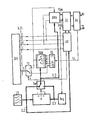
- a subscriber station with a data terminal DEE is indicated in a block diagram, which may be a data terminal that is connected to a transmission line via an interface in accordance with CCITT recommendation X.21 and a series of circuit devices, to which one Signals in the incoming transmission line Lan and signals in the outgoing transmission line Lab belong.
- the circuit devices located between the transmission line and the data terminal DEE form an overall remote switching device, which in the present case includes is used for the automatic setting of data signal rates.
- the remote switching device shown in the drawing includes, among other things, a sequence controller AS, which is connected to the data terminal DEE via lines C, T, R and I.
- Line C is a Control line via which the control signals required for the sequential control system are supplied.
- the line T is a transmission line, via which signaling information is supplied to the sequence controller AS from the data terminal DEE.
- the line R is a reception line, via which signaling information can be supplied to the data terminal DEE by the sequence controller AS.
- Line I is a control line via which the sequential control system AS is able to deliver control signals to the data terminal DEE.
- the sequential control system AS which handles the respectively required control processes, is connected on the input and output side to a transmission control system US, which controls the handling of transmission processes.
- the transmission control ÜS is connected on the input and output sides via a transmission unit ÜE to the transmission line already mentioned above, that is to say to the two lines Lan and Lab.
- the transmission unit ÜE essentially serves as an adaptation device between the transmission controller ÜS and the transmission line.
- the transmission controller ÜS is connected via a data signal in the incoming direction forwarding line Dan and via a data signal in the outgoing transmission direction line Dab to a bit rate adaptation device BRA, which is also connected on the input and output side to the transmission line and to the reception line R of the data terminal DEE.
- the task of this bit rate adaptation device BRA is to balance the data used in the associated subscriber station or in the associated data terminal DEE signal rate and the decisive on the transmission line Lan, Lab data signal rate, with respect to which it can be assumed that it is normally fixed and higher than the data signal rate for which the data terminal DEE is designed.
- the remote switching device shown in the drawing also includes a clock selection circuit TAW, which may be connected on the input side to a clock generator TG which emits clock signals from different outputs T1 to TN at different clock rates, which may be linked to a transmission clock serving as a reference clock. From a further output To, the clock generator TG emits clock pulses which correspond to a fixed data signal rate, which in the present case may be a data signal rate of 2.4 kbit / s, with which signaling information from or to the individual subscriber stations or Data terminals are transmitted.
- a clock selection circuit TAW which may be connected on the input side to a clock generator TG which emits clock signals from different outputs T1 to TN at different clock rates, which may be linked to a transmission clock serving as a reference clock. From a further output To, the clock generator TG emits clock pulses which correspond to a fixed data signal rate, which in the present case may be a data signal rate of 2.4 kbit / s, with which signaling information from or
- the clock selection circuit TAW which is shown schematically as a selector, is connected on the output side to the one input connection of a switch TU having two input connections and one output connection, which is connected with its output connection via a line S to the associated data terminal DEE, which is connected via this line S to selected clock pulses are supplied.
- the changeover switch TU is directly connected with its other input connection to the output To of the clock generator TG.
- the changeover switch TU With an actuating input, the changeover switch TU is connected via a control line X to the sequence control AS mentioned above, which then reverses the changeover switch TU from its normal switch position shown in the drawing into its other switch position when the signaling phase with the on Position of the selected data transmission rate is complete and data signals sent by the data terminal DEE must now be transferred to the bit rate adaptation device BRA or data signals emitted by the latter must be forwarded to the data terminal DEE.
- the output of the clock selection circuit TAW is connected to a clock input of the bit rate adaptation device BRA.
- the clock selection circuit TAW considered above is part of a setting device associated with the remote switching device shown in the drawing, which also includes a switch Sw, via whose output side setting signals for the clock selection circuit TAW and for the bit rate adaptation device BRA are emitted.
- the changeover switch Sw is connected on the input side to the output of a coding switch CS or to the output of a register Reg.
- a comparator K is connected to the output sides of the coding switch CS and the register Reg, which compares the signals fed to it from the register Reg via a line or line group CL1 with the signals supplied from the coding switch CS via a line or line group CL2, which codes in binary form Value assignments to the data signal rates to be characterized by them may be.
- the signals emitted by the coding switch CS provide overall information about the data signal rate with which the associated subscriber station or the associated data terminal can work.
- the comparator K compares this information with an information signal stored in the register Reg by the transmission controller ÜS, which information signal was given by another subscriber station in the course of establishing a connection or after a connection has already been established to the subscriber station shown in the drawing that as a calling part subscriber station may be considered, and which provides information about its own data signal rate in said information signal.
- the changeover switch Sw is in the switch position shown in the drawing when this particular output signal occurs.
- the one designated by the coding switch is selected as the common clock signal rate value if, as assumed, by comparing the information with the information signal mentioned, this value has been found to be equal to or lower than that desired by the remote remote switching device.
- This variable is used in the circuit arrangement under consideration via the changeover switch Sw for the corresponding setting of the clock selection circuit TAW.
- the clock selection circuit TAW emits a clock signal with a clock signal rate, which is given by the previously mentioned comparison result of the comparison carried out by the comparator K. In other words, this means that there is a direct association between the respectively selected clock signal rate and the data signal rate.
- variable used to set the clock selection circuit TAW is also delivered via a line or line arrangement CL3 to the bit rate adaptation circuit BRA, to which all the necessary information is supplied in order to transmit data signals at the correct data signal rate to and from the associated data terminal DEE and otherwise an adjustment between this data signal rate and, in contrast, the normally higher data signal rate, which is decisive on the transmission line Lan, Lab.
- register Reg With regard to the register Reg considered above, it should also be noted that its register input is connected to the output of the transmission control ÜS already considered above. Via this transmission control ÜS, only the respective information signal is fed to the register Reg, which has been supplied to the relevant transmission control ÜS in the bit stream of the entire signaling information from the transmission line.
- a call is to be made from a calling subscriber station with the structure shown in the drawing to another, appropriately constructed subscriber station.
- the first subscriber station is called the calling subscriber station and the second subscriber station is called the subscriber station to be called.
- the calling subscriber station initially emits signaling information which, for example, contains the call number of the subscriber station to be called.
- the clock signal from the output To of the clock generator TG is used, that is to say a clock signal with a clock signal rate of, for example, 2.4 kbit / s, in order to provide the corresponding signaling information to be taken over by the data terminal DEE and passed on via the sequence control AS, for example in a reserved time slot of the transmission control US operating in the manner of a multiplexer.
- the relevant calling subscriber station also emits an information signal which designates the nominal data signal rate desired or just possible from the calling subscriber station concerned.
- This information signal can either be output by the terminal DEE or can also be derived automatically from the position of the associated coding switch CS, which controls the associated sequence control AS accordingly via the line or line arrangement .C, so that the information signal in question relating to the one to be called or already called Participant position is transmitted.
- the information signal fed to the relevant subscriber station to be called or called is compared in this subscriber station with the information available there or with the information available there relating to the data signal rate with which the subscriber station called or called can work.
- the data signal rate that is the lower (that is the largest possible together) data signal rate of the practically compared data signal rates is then selected in the subscriber station to be called or called.
- the processes thus taking place in the subscriber station to be called or called correspond entirely to the processes already considered above in connection with the explanation of the circuit structure.
- the data signal rate in the calling subscriber station may need to be set. For this purpose, a corresponding information or setting signal is transmitted back to the calling subscriber station from the calling or called subscriber station under consideration. If the data signal rate selected or set in the subscriber station to be called or called is lower than the data signal rate that was initially specified by the calling subscriber station as the desired or possible nominal data signal rate, the data calling rate is only set in the relevant calling subscriber station has already been set in the subscriber station to be called or called. The same processes take place in the calling subscriber station as have been explained above with regard to the subscriber station to be called or called.
- both the subscriber station to be called or called and the calling subscriber station are set to one and the same data signal rate.
- This data signal rate is the currently possible maximum effective data signal rate that the two subscriber stations can use to transmit data to one another at the moment.
- this information signal is transmitted to a subscriber station to be called or called.
- the same processes which have been explained above, take place both in the subscriber station to be called and in the called subscriber station on the one hand and in the calling subscriber station on the other hand.
Abstract
Description
Die Erfindung bezieht sich auf ein Verfahren und auf eine Schaltungsanordnung zum Übertragen von Datensignalen zwischen Teilnehmerstellen eines Datennetzes, an dem für die Abgabe und. für die Aufnahme von Datensignalen mit unterschiedlichen Datensignalraten ausgelegte Teilnehmerstellen angeschlossen sind.The invention relates to a method and to a circuit arrangement for transmitting data signals between subscriber stations of a data network on which for the delivery and. subscriber stations designed for receiving data signals with different data signal rates are connected.
Im Zusammenhang mit einem geplanten dienstintegrierten Digitalnetz (ISDN) ist es bereits bekannt (Zeitschrift "telcom report" 3 (1980) Heft 3, Seiten 222 bis 227, insbesondere Seite 225), den Teilnehmerstellen einer Vermittlungsanlage unterschiedliche Übertragungskapazitäten bereitzustellen, indem den betreffenden Teilnehmerstellen eine Mehrzahl von 64-kbit/s-Übertragungskanälen zur Verfügung gestellt wird. In diesem Zusammenhang ist es jedoch nicht bekannt, wie Verbindungen zwischen derartigen.Teilnehmerstellen herzustellen sind, wenn es darum geht, daß unterschiedliche Übertragungskapazitäten für die jeweilige Verbindung zur Auswahl stehen.In connection with a planned integrated service digital network (ISDN) it is already known (magazine "telcom report" 3 (1980) Issue 3, pages 222 to 227, in particular page 225) to provide the subscriber stations of a switching system with different transmission capacities by providing the subscriber stations concerned with one A plurality of 64 kbit / s transmission channels is provided. In this context, however, it is not known how connections between such subscriber stations are to be made when it comes to the fact that different transmission capacities are available for the respective connection.
Der Erfindung liegt nun die Aufgabe zugrunde, einen Weg zu zeigen, wie in einem Datennetz Verbindungen zwischen Teilnehmerstellen hergestellt werden können, die für unterschiedliche Datensignalraten eingerichtet bzw. gerade in Verbindungen einbeziehbar sind.The invention is based on the object of showing a way in which connections can be established in a data network between subscriber stations which are set up for different data signal rates or can be included in connections.
Gelöst wird die vorstehend aufgezeigte Aufgabe bei einem Verfahren der eingangs genannten Art erfindungsgemäß dadurch, daß von einer rufenden Teilnehmerstelle im Zuge des Aufbaus einer Verbindung oder danach ein Informationssignal abgegeben wird, mit dem die für die von der rufenden Teilnehmerstelle aus gewünschte oder mögliche nominelle Datensignalrate bezeichnet wird, daß das betreffende Informationssignal mit für die jeweils anzurufende bzw. angerufene Teilnehmerstelle vorhandene Angaben über die Datensignalrate, mit der die betreffende anzurufende bzw. angerufene Teilnehmerstelle zu arbeiten vermag, verglichen wird, daß auf den Vergleich des Informationssignals mit den genannten Angaben hin in der anzurufenden bzw. angerufenen Teilnehmerstelle diejenige Datensignalrate eingestellt wird, welche in Anbetracht der durch das Informationssignal gegebenen Datensignalrate die höchste gemeinsame Datensignalrate für die miteinander zu verbindenden bzw. bereits verbundenen Teilnehmerstellen ist, und daß durch Übertragen eines Einstellsignals in der rufenden Teilnehmerstelle dieselbe Datensignalrate eingestellt wird, die-für die anzurufende bzw. angerufene Teilnehmerstelle eingestellt worden ist.The object outlined above is achieved according to the invention in a method of the type mentioned at the outset in that an information signal is emitted by a calling subscriber station in the course of establishing a connection or thereafter, by means of which the nominal data signal rate desired or possible for the calling subscriber station is indicated is that the information signal in question is compared with information about the data signal rate with which the particular calling or called subscriber station is able to work for the particular subscriber station to be called or called, that upon comparison of the information signal with the stated information in the to be called or called the subscriber station that data signal rate is set which, in view of the data signal rate given by the information signal, the highest common data signal rate for the subscriber stations to be connected or already connected and that by transmitting a setting signal in the calling subscriber station the same data signal rate is set which has been set for the subscriber station to be called or called.
Die Erfindung bringt den. Vorteil mit sich, daß auf besonders einfache Weise erreicht ist, daß Datensignale auch zwischen solchen an dem erwähnten Datennetz angeschlossenen Teilnehmerstellen hergestellt werden können, deren nominelle Datensignalraten unterschiedlich, jedoch nicht höher als die Übertragungskapazität der Verbindungswege sind. Von Vorteil ist ferner, daß die Einstellung der für die jeweilige Verbindung maßgebenden Datensignalrate bzw. Übertragungsgeschwindigkeit zwischen den jeweils miteinander zu verbindenden verbundenen Teilnehmerstellen automatisch erfolgen kann, ohne daß dazu gesonderte Einstellvorgänge in vermittlungstechnischen oder übertragungstechnischen Einrichtungen auszuführen sind.The invention brings the. Advantage with it that it is achieved in a particularly simple manner that data signals can also be produced between those subscriber stations connected to the mentioned data network, the nominal data signal rates of which are different, but not higher than the transmission capacity of the connection paths. It is also advantageous that the setting of the data signal rate or transmission speed which is decisive for the respective connection between the connected subscriber stations to be connected to one another is carried out automatically conditions can be carried out without having to carry out separate adjustment processes in switching or transmission facilities.
Vorzugsweise wird bei bereits vorliegender Einstellung der jeweils gerade maximal möglichen Datensignalrate in der jeweils anzurufenden bzw. angerufenen Teilnehmerstelle und Auftreten eines Informationssignals, welches eine Datensignalrate betrifft, die mindestens gleich der erstgenannten Datensignalrate ist, lediglich ein Einstellsignal zur Einstellung der erstgenannten Datensignalrate für die rufende Teilnehmerstelle abgegeben. Hierdurch ergibt sich der Vorteil eines besonders geringen Steuerungsaufwands für die erforderliche Einstellung der für die jeweilige Datensignalübertragung zu benutzenden Datensignalraten.When the currently maximum possible data signal rate has already been set in the respective subscriber station to be called or called and an information signal which relates to a data signal rate which is at least equal to the first-mentioned data signal rate, only a setting signal for setting the first-mentioned data signal rate for the calling subscriber station is preferred submitted. This results in the advantage of a particularly low control outlay for the necessary setting of the data signal rates to be used for the respective data signal transmission.
Zur Durchführung des Verfahrens gemäß der Erfindung ist es zweckmäßig, eine Schaltungsanordnung zu verwenden, die dadurch gekennzeichnet ist, daß jeder Teilnehmerstelle ein Fernschaltgerät zugehörig ist, mit dem die jeweilige Teilnehmerstelle an einer Übertragungsleitung angeschlossen ist, daß im Fernschaltgerät jeder Teilnehmerstelle Angaben darüber gespeichert sind, für welche nominelle maximale Datensignalrate die betreffende Teilnehmerstelle eingerichtet bzw. gerade betriebsbereit ist, daß ein in jedem Fernschaltgerät enthaltener Komparator die in diesem jeweils gespeicherten genannten Angaben mit einem von einer rufenden Teilnehmerstelle her . zugeführten Informationssignal zu vergleichen gestattet, welches die von der betreffenden rufenden Teilnehmerstelle für eine Verbindung gerade geforderte oder gerade mögliche Datensignalrate bezeichnet, daß mit dem Komparator eine Einstelleinrichtung verbunden ist, in der nach Maßgabe des Ausgangssignals des Komparators in der zugehörigen Teilnehmerstelle diejenige Datensignalrate eingestellt wird, welche die größte gemeinsame Datensignalrate der durch das Informationssignal und durch die genannten Angaben bezeichneten Datensignalraten ist, und daß von der Einstelleinrichtung des Fernschaltgeräts der jeweiligen anzurufenden bzw. angerufenen Teilnehmerstelle entsprechende Einstellsignale an das Fernschaltgerät der jeweils rufenden Teilnehmerstelle abgebbar sind. Hierdurch ergibt sich der Vorteil eines besonders geringen schaltungstechnischen Aufwands, um für die in jeweils eine Verbindung einzubeziehenden bzw. einbezogenen Teilnehmerstellen die gemeinsam zu benutzende bzw. maximal mögliche Datensignalrate einzustellen.To carry out the method according to the invention, it is expedient to use a circuit arrangement which is characterized in that each subscriber station is associated with a remote switching device with which the respective subscriber station is connected to a transmission line, that information about it is stored in the remote switching device of each subscriber station, For which nominal maximum data signal rate the subscriber station in question is set up or is just ready for operation, that a comparator contained in each remote switching device contains the information stored therein in each case from a calling subscriber station. supplied supplied to compare information signal, which denotes the data signal rate currently required or just possible for a connection by the calling subscriber station in question, that an adjusting device is connected to the comparator is, in accordance with the output signal of the comparator in the associated subscriber station that data signal rate is set which is the largest common data signal rate of the data signal rates indicated by the information signal and by the above-mentioned information, and that the setting device of the remote switching device of the respective to be called or called Corresponding setting signals can be output to the remote switching device of the calling subscriber station. This results in the advantage of a particularly low outlay in terms of circuitry in order to set the jointly used or maximum possible data signal rate for the subscriber stations to be included or included in each connection.
Zweckmäßigerweise weist jedes Fernschaltgerät eine Taktauswahlschaltung auf, die Taktsignale entsprechend den verschiedenen Datensignalraten abzugeben gestattet und die von der zugehörigen Einstelleinrichtung für die Abgabe der der jeweils in Frage kommenden Datensignalrate entsprechenden Taktsignale einstellbar ist. Dies bringt den Vorteil mit sich, daß für die jeweils in Frage kommenden Datensignalraten die richtigen Taktsignale bereitgestellt werden können.Each remote switching device expediently has a clock selection circuit which allows clock signals to be output in accordance with the various data signal rates and which can be set by the associated setting device for the output of the clock signals corresponding to the data signal rate in question. This has the advantage that the correct clock signals can be provided for the data signal rates in question.
Vorzugsweise gibt die Taktauswahlschaltung in ihrer Ausgangsstellung Taktsignale entsprechend einer festgelegten Datensignalrate ab. Diese Maßnahme eröffnet in vorteilhafter Weise die Möglichkeit, die betreffende festgelegte Datensignalrate für die Übertragung von Signalisierungsinformationen heranzuziehen, die im Zuge des Aufbaus von Verbindungen zwischen Teilnehmerstellen zu übertragen sind und mit denen die Informationssignale übertragen werden können, welche iie für die Datensignalübertragung jeweils gewünschten bzw. möglichen Datensignalraten betreffen.In its initial position, the clock selection circuit preferably emits clock signals in accordance with a fixed data signal rate. This measure advantageously opens up the possibility of using the specified data signal rate in question for the transmission of signaling information which is to be transmitted in the course of establishing connections between subscriber stations and with which the information signals which can be transmitted iie relate to the desired or possible data signal rates for the data signal transmission.
Von Vorteil ist es ferner, wenn die Einstelleinrichtung jedes Fernschaltgeräts eine Bitratenanpassungseinrichtung aufweist, welche einen Ausgleich zwischen der bei der zugehörigen Teilnehmerstelle eingestellten Datensignalrate und einer auf einer mit der betreffenden Teilnehmerstelle verbundenen Übertragungsleitung maßgebenden höheren Datensignalrate bewirkt. Durch diese Maßnahme läßt sich ein taktgebundener Betrieb mit fester Taktfrequenz bei der Übertragung der Datensignale über Übertragungsleitungen erzielen.It is also advantageous if the setting device of each remote switching device has a bit rate adaptation device which effects a balance between the data signal rate set at the associated subscriber station and a higher data signal rate which is decisive on a transmission line connected to the relevant subscriber station. With this measure, clock-based operation with a fixed clock frequency can be achieved in the transmission of the data signals via transmission lines.
Anhand einer Zeichnung wird die Erfindung nachstehend beispielsweise näher erläutert.The invention is explained in more detail below with reference to a drawing.
In der Zeichnung ist in einem Blockschaltbild eine Teilnehmerstelle mit einer Datenendeinrichtung DEE angedeutet, bei der es sich um ein Datenendgerät handeln mag, das über eine Schnittstelle gemäß CCITT-Empfehlung X.21 und eine Reihe von Schaltungseinrichtungen mit einer übertragungsleitung verbunden ist, zu der eine Signale in ankommender Übertragungsrichtung übertragende Leitung Lan und eine Signale in abgehender Übertragungsrichtung übertragende Leitung Lab gehören. Die zwischen der Übertragungsleitung und dem Datenendgerät DEE liegenden Schaltungseinrichtungen bilden insgesamt ein Fernschaltgerät, welches im vorliegenden Fall u.a. zur automatischen Einstellung von Datensignalraten dient.In the drawing, a subscriber station with a data terminal DEE is indicated in a block diagram, which may be a data terminal that is connected to a transmission line via an interface in accordance with CCITT recommendation X.21 and a series of circuit devices, to which one Signals in the incoming transmission line Lan and signals in the outgoing transmission line Lab belong. The circuit devices located between the transmission line and the data terminal DEE form an overall remote switching device, which in the present case includes is used for the automatic setting of data signal rates.
Das in der Zeichnung dargestellte Fernschaltgerät umfaßt unter anderem eine Ablaufsteuerung AS, die über Leitungen C, T, R und I mit dem Datenendgerät DEE verbunden ist. Bei der Leitung C handelt es sich um eine Steuerleitung, über die der Ablaufsteuerung erforderliche Steuersignale zugeführt werden. Die Leitung T ist eine Sendeleitung, über die der Ablaufsteuerung AS vom Datenendgerät DEE Signalisierungsinformationen zugeführt werden. Die Leitung R ist eine Empfangsleitung, über die dem Datenendgerät DEE von der Ablaufsteuerung AS Signalisierungsinformationen zugeführt werden können. Die Leitung I ist eine Steuerleitung, über die die Ablaufsteuerung AS an das Datenendgerät DEE Steuersignale abzugeben'vermag.The remote switching device shown in the drawing includes, among other things, a sequence controller AS, which is connected to the data terminal DEE via lines C, T, R and I. Line C is a Control line via which the control signals required for the sequential control system are supplied. The line T is a transmission line, via which signaling information is supplied to the sequence controller AS from the data terminal DEE. The line R is a reception line, via which signaling information can be supplied to the data terminal DEE by the sequence controller AS. Line I is a control line via which the sequential control system AS is able to deliver control signals to the data terminal DEE.
Die Ablaufsteuerung AS, welche die jeweils erforderlichen Steuerungsvorgänge abwickelt, ist eingangs-und ausgangsseitig an einer Übertragungssteuerung ÜS angeschlossen, welche die Abwicklung von Übertragungsvorgängen steuert.The sequential control system AS, which handles the respectively required control processes, is connected on the input and output side to a transmission control system US, which controls the handling of transmission processes.
Die Übertragungssteuerung ÜS ist eingangs- und ausgangsseitig über eine Übertragungseinheit ÜE an der oben bereits erwähnten Übertragungsleitung angeschlossen, das heißt an den beiden Leitungen Lan und Lab. Die Übertragungseinheit ÜE dient im wesentlichen als Anpassungseinrichtung zwischen der Übertragungssteuerung ÜS und der Übertragungsleitung.The transmission control ÜS is connected on the input and output sides via a transmission unit ÜE to the transmission line already mentioned above, that is to say to the two lines Lan and Lab. The transmission unit ÜE essentially serves as an adaptation device between the transmission controller ÜS and the transmission line.
Die Übertragungssteuerung ÜS ist über eine Datensignale in ankommender Richtung weiterleitende Leitung Dan sowie über eine Datensignale in abgehender Übertragungsrichtung übertragende Leitung Dab mit einer Bitratenanpassungseinrichtung BRA verbunden, die eingangs- und ausgangsseitig ferner mit der Sendeleitung und mit der Empfangsleitung R des Datenendgerätes DEE verbunden ist. Die Aufgabe dieser Bitratenanpassungseinrichtung BRA besteht darin, einen Ausgleich zwischen der in der zugehörigen Teilnehmerstelle bzw. beim zugehörigen Datenendgerät DEE benutzten Datensignalrate und der auf der Ubertragungsleitung Lan, Lab maßgebenden Datensignalrate vorzunehmen, bezüglich der davon auszugehen ist, daß sie normalerweise fest vorgegeben und höher ist als die Datensignalrate, für die das betreffende Datenendgerät DEE ausgelegt ist.The transmission controller ÜS is connected via a data signal in the incoming direction forwarding line Dan and via a data signal in the outgoing transmission direction line Dab to a bit rate adaptation device BRA, which is also connected on the input and output side to the transmission line and to the reception line R of the data terminal DEE. The task of this bit rate adaptation device BRA is to balance the data used in the associated subscriber station or in the associated data terminal DEE signal rate and the decisive on the transmission line Lan, Lab data signal rate, with respect to which it can be assumed that it is normally fixed and higher than the data signal rate for which the data terminal DEE is designed.
Zu dem in der Zeichnung dargestellten Fernschaltgerät gehört ferner eine Taktauswahlschaltung TAW, die ein- - gangsseitig mit einem Taktgenerator TG verbunden sein mag, der von verschiedenen Ausgängen T1 bis TN Taktsignale mit unterschiedlichen Taktraten abgibt, die an einen als Referenztakt dienenden Ubertragungstakt gebunden sein können. Von einem weiteren Ausgang To gibt der Taktgenerator TG Taktimpulse ab, die einer festgelegten Datensignalrate entsprechen, bei der es sich im vorliegenden Fall beispielsweise um eine Datensignalrate von 2,4 kbit/s handeln mag, mit der Signalisierungsinformationen von bzw. zu den einzelnen Teilnehmerstellen bzw. Datenendeinrichtungen übertragen werden.The remote switching device shown in the drawing also includes a clock selection circuit TAW, which may be connected on the input side to a clock generator TG which emits clock signals from different outputs T1 to TN at different clock rates, which may be linked to a transmission clock serving as a reference clock. From a further output To, the clock generator TG emits clock pulses which correspond to a fixed data signal rate, which in the present case may be a data signal rate of 2.4 kbit / s, with which signaling information from or to the individual subscriber stations or Data terminals are transmitted.
Die Taktauswahlschaltung TAW, die schematisch als Wähler dargestellt ist, ist ausgangsseitig mit dem einen Eingangsanschluß eines zwei Eingangsanschlüsse und einen Ausgangsanschluß aufweisenden Umschalters TU verbünden, der mit seinem Ausgangsanschluß über eine Leitung S an dem zugehörigen Datenendgerät DEE angeschlossen ist, welchem über diese Leitung S die jeweils ausgewählten Taktimpulse zugeführt werden. Der Umschalter TU ist mit seinem anderen Eingangsanschluß an dem Ausgang To des Taktgenerators TG direkt angeschlossen. Mit einem Betätigungseingang ist der Umschalter TU über eine Steuerleitung X mit der oben erwähnten Ablaufsteuerung AS verbunden, welche den Umschalter TU aus seiner in der Zeichnung dargestellten normalen Schalterstellung dann in seine andere Schalterstellung umsteuert, wenn die Signalisierungsphase mit der EinStellung der ausgewählten Datenübertragungsrate abgeschlossen ist und nun vom Datenendgerät DEE gesendete Datensignale an die Bitratenanpassungseinrichtung BRA zu übergeben bzw. von dieser abgegebene Datensignale an das Datenendgerät DEE weiterzuleiten sind. Der Ausgang der Taktauswahlschaltung TAW ist dazu mit einem Takteingang der Bitratenanpassungseinrichtung BRA verbunden.The clock selection circuit TAW, which is shown schematically as a selector, is connected on the output side to the one input connection of a switch TU having two input connections and one output connection, which is connected with its output connection via a line S to the associated data terminal DEE, which is connected via this line S to selected clock pulses are supplied. The changeover switch TU is directly connected with its other input connection to the output To of the clock generator TG. With an actuating input, the changeover switch TU is connected via a control line X to the sequence control AS mentioned above, which then reverses the changeover switch TU from its normal switch position shown in the drawing into its other switch position when the signaling phase with the on Position of the selected data transmission rate is complete and data signals sent by the data terminal DEE must now be transferred to the bit rate adaptation device BRA or data signals emitted by the latter must be forwarded to the data terminal DEE. For this purpose, the output of the clock selection circuit TAW is connected to a clock input of the bit rate adaptation device BRA.
Die vorstehend betrachtete Taktauswahlschaltung TAW ist Bestandteil einer dem in der Zeichnung dargestellten Fernschaltgerät zugehörigen Einstelleinrichtung, zu der ferner ein Schalter Sw gehört, über dessen Ausgangsseite Einstellsignale für die Taktauswahlschaltung TAW und für die Bitratenanpassungseinrichtung BRA abgegeben werden. Der Umschalter Sw ist eingangsseitig am Ausgang eines Codierschalters CS bzw. am Ausgang eines Registers Reg angeschlossen. Mit den Ausgangsseiten des Codierschalters CS und des Registers Reg ist ein Komparator K verbunden, der die ihm von dem Register Reg über eine Leitung bzw. Leitungsgruppe CL1 zugeführten Signale mit den von dem Codierschalter CS über eine Leitung bzw. Leitungsgruppe CL2 zugeführten Signalenvergleicht, die binärkodierte Wertzuweisungen zu den durch sie zu kennzeichnenden Datensignalraten sein mögen. Die von dem Codierschalter CS abgegebenen Signale stellen insgesamt Angaben über die Datensignalrate bereit, mit der die zugehörige Teilnehmerstelle bzw. das zugehörige Datenendgerät zu arbeiten vermag. Diese Angaben vergleicht der Komparator K mit einem in dem Register Reg von der Übertragungssteuerung ÜS her gespeicherten Informationssignal, welches im Zuge des Aufbaus einer Verbindung bzw. nach bereits erfolgtem Aufbau einer Verbindung zu der in der Zeichnung dargestellten Teilnehmerstelle hin von einer anderen Teilnehmerstelle abgegeben worden ist, die als rufende Teilnehmerstelle betrachtet werden mag, und die in dem genannten Informationssignal Angaben über ihre eigene Datensignalrate bereitstellt. Der Komparator gibt von seinem mit < oder = bezeichneten Ausgängen dann ein bestimmtes Ausgangssignal ab, wenn der Wert des in dem Register Reg zwischengespeicherten Informationssignals mindestens gleich dem Wert der durch den Codierschalter CS bereitgestellten Angaben ist. In diesem Falle befindet sich der Umschalter Sw bei Auftreten dieses bestimmten Ausgangssignals in seiner aus der Zeichnung ersichtlichen Schalterstellung. In dieser Schalterstellung wird dann als gemeinsamer Taktsignalratenwert der durch den Codierschalter bezeichnete ausgewählt, wenn sich, wie angenommen, durch den Vergleich der Angaben mit dem erwähnten Informationssignal dieser Wert als gleich bzw. niedriger als vom fernen Fernschaltgerät gewünscht ergeben hat. Diese Größe wird in der betrachteten Schaltungsanordnung über den Umschalter Sw zur entsprechenden Einstellung der Taktauswahlschaltung TAW herangezogen. Die Taktauswahlschaltung TAW gibt auf ihre Einstellung hin ausgangsseitig ein Taktsignal mit einer Taktsignalrate ab, welche durch das zuvor erwähnte Vergleichsergebnis des durch den Komparator K durchgeführten Vergleichs gegeben ist. Mit anderen Worten ausgedrückt heißt dies, daß eine direkte Zuordnung zwischen der jeweils ausgewählten Taktsignalrate und der Datehsignalrate erfolgt.The clock selection circuit TAW considered above is part of a setting device associated with the remote switching device shown in the drawing, which also includes a switch Sw, via whose output side setting signals for the clock selection circuit TAW and for the bit rate adaptation device BRA are emitted. The changeover switch Sw is connected on the input side to the output of a coding switch CS or to the output of a register Reg. A comparator K is connected to the output sides of the coding switch CS and the register Reg, which compares the signals fed to it from the register Reg via a line or line group CL1 with the signals supplied from the coding switch CS via a line or line group CL2, which codes in binary form Value assignments to the data signal rates to be characterized by them may be. The signals emitted by the coding switch CS provide overall information about the data signal rate with which the associated subscriber station or the associated data terminal can work. The comparator K compares this information with an information signal stored in the register Reg by the transmission controller ÜS, which information signal was given by another subscriber station in the course of establishing a connection or after a connection has already been established to the subscriber station shown in the drawing that as a calling part subscriber station may be considered, and which provides information about its own data signal rate in said information signal. The comparator outputs a specific output signal from its outputs labeled <or = when the value of the information signal buffered in the register Reg is at least equal to the value of the information provided by the coding switch CS. In this case, the changeover switch Sw is in the switch position shown in the drawing when this particular output signal occurs. In this switch position, the one designated by the coding switch is selected as the common clock signal rate value if, as assumed, by comparing the information with the information signal mentioned, this value has been found to be equal to or lower than that desired by the remote remote switching device. This variable is used in the circuit arrangement under consideration via the changeover switch Sw for the corresponding setting of the clock selection circuit TAW. On its output side, the clock selection circuit TAW emits a clock signal with a clock signal rate, which is given by the previously mentioned comparison result of the comparison carried out by the comparator K. In other words, this means that there is a direct association between the respectively selected clock signal rate and the data signal rate.
Die zur Einstellung der Taktauswahlschaltung TAW verwendete Größe wird ferner über eine Leitung bzw. Leitungsanordnung CL3 an die Bitratenanpassungsschaltung BRA abgegeben, der damit alle notwendigen Informationen zugeführt sind, um Datensignale mit der richtigen Datensignalrate zu bzw. von dem zugehörigen Datenendgerät DEE zu übertragen und im übrigen eine Anpassung zwischen dieser Datensignalrate und der demgegenüber normalerweise höheren Datensignalrate vorzunehmen, die auf der Übertragungsleitung Lan, Lab maßgebend ist.The variable used to set the clock selection circuit TAW is also delivered via a line or line arrangement CL3 to the bit rate adaptation circuit BRA, to which all the necessary information is supplied in order to transmit data signals at the correct data signal rate to and from the associated data terminal DEE and otherwise an adjustment between this data signal rate and, in contrast, the normally higher data signal rate, which is decisive on the transmission line Lan, Lab.
Bezüglich des vorstehend betrachteten Registers Reg sei noch angemerkt, daß dieses mit seinem Registereingang am Ausgang der oben bereits betrachteten Übertragungssteuerung ÜS angeschlossen ist. Über diese Übertragungssteuerung ÜS wird dem Register Reg nur das jeweilige Informationssignal zugeführt, welches der betreffenden Übertragungssteuerung ÜS im Bitstrom der ganzen Signalisierungsinformation von der Übertragungsleitung her zugeführt worden ist.With regard to the register Reg considered above, it should also be noted that its register input is connected to the output of the transmission control ÜS already considered above. Via this transmission control ÜS, only the respective information signal is fed to the register Reg, which has been supplied to the relevant transmission control ÜS in the bit stream of the entire signaling information from the transmission line.
Nachdem zuvor der Aufbau der in der Zeichnung dargestellten Schaltungsanordnung betrachtet worden ist, soll nunmehr die Arbeitsweise dieser Schaltungsanordnung näher betrachtet werden.After the structure of the circuit arrangement shown in the drawing has been considered, the mode of operation of this circuit arrangement will now be considered in more detail.
Zunächst sei davon ausgegangen, daß von einer rufenden Teilnehmerstelle mit dem in der Zeichnung gezeigten Aufbau aus eine Verbindung hergestellt werden soll zu einer anderen, entsprechend aufgebauten Teilnehmerstelle. Die erstgenannte Teilnehmerstelle wird als rufende Teilnehmerstelle bezeichnet, und die zweite Teilnenmerstelle wird als anzurufende Teilnehmerstelle bezeichnet.First of all, it is assumed that a call is to be made from a calling subscriber station with the structure shown in the drawing to another, appropriately constructed subscriber station. The first subscriber station is called the calling subscriber station and the second subscriber station is called the subscriber station to be called.
Von der rufenden Teilnehmerstelle wird zunächst in einer Signalisierungsphase eine Signalisierungsinformation abgegeben, welche beispielsweise die Rufnummer der gewünschten anzurufenden Teilnebmerstelle enthält. Hierzu wird das Taktsignal vom Ausgang To des Taktgenerators TG benutzt, das sei ein Taktsignal mit einer Taktsignalrate von beispielsweise 2,4 kbit/s, um damit die entsprechende Signalisierungsinformation von dem Datenendgerät DEE zu übernehmen und weitergeleitet über die Ablaufsteuerung AS, z.B. in einen dafür reservierten Zeitschlitz der in der Art eines Multiplexers arbeitenden Ubertragungssteuerung ÜS einzuführen. In der Signalisierungsphase wird ferner von der betreffenden rufenden Teilnehmerstelle ein Informationssignal abgegeben, welches die von der betreffenden rufenden Teilnehmerstelle aus gewünschte oder gerade mögliche nominelle Datensignalrate bezeichnet. Dieses Informationssignal kann entweder vom Endgerät DEE abgegeben oder auch automatisch aus der Stellung des zugehörigen Codierschalters CS abgeleitet werden, der über die Leitung bzw. Leitungsanordnung .C die zugehörige Ablaufsteuerung AS entsprechend ansteuert, so daß das infrage kommende Informationssignal zu der anzurufenden bzw, bereits angerufenen Teilnehmerstelle hin übertragen wird.In a signaling phase, the calling subscriber station initially emits signaling information which, for example, contains the call number of the subscriber station to be called. For this purpose, the clock signal from the output To of the clock generator TG is used, that is to say a clock signal with a clock signal rate of, for example, 2.4 kbit / s, in order to provide the corresponding signaling information to be taken over by the data terminal DEE and passed on via the sequence control AS, for example in a reserved time slot of the transmission control US operating in the manner of a multiplexer. In the signaling phase, the relevant calling subscriber station also emits an information signal which designates the nominal data signal rate desired or just possible from the calling subscriber station concerned. This information signal can either be output by the terminal DEE or can also be derived automatically from the position of the associated coding switch CS, which controls the associated sequence control AS accordingly via the line or line arrangement .C, so that the information signal in question relating to the one to be called or already called Participant position is transmitted.
In der anzurufenden bzw. angerufenen Teilnehmerstelle laufen nun folgende Funktionen ab. Das der betreffenden anzurufenden bzw. angerufenen Teilnehmerstelle zugeführte Informationssignal wird in dieser Teilnehmerstelle mit der dort vorhandenen Angabe bzw. mit den dort vorhandenen Angaben verglichen, die die Datensignalrate betrifft bzw. betreffen, mit der diese anzurufende bzw. angerufene Teilnebmerstelle zu arbeiten vermag. Als Ergebnis dieses Vergleichs wird dann in der betrechteten anzurufenden bzw. angerufenen Teilnehmerstelle diejenige Datensignalrate ausgewählt, welche die niedere (das ist die größte gemeinsam mögliche) Datensignalrate der praktisch miteinander verglichenen Datensignalraten ist. Die damit in der anzurufenden bzw. angerufenen Teilnehmerstelle ablaufenden Vorgänge entsprechen völlig den oben bereits im Zusammenhang mit der Erläuterung des Schaltungsaufbaus betrachteten Vorgängen.The following functions now run in the subscriber station to be called or called. The information signal fed to the relevant subscriber station to be called or called is compared in this subscriber station with the information available there or with the information available there relating to the data signal rate with which the subscriber station called or called can work. As a result of this comparison, the data signal rate that is the lower (that is the largest possible together) data signal rate of the practically compared data signal rates is then selected in the subscriber station to be called or called. The processes thus taking place in the subscriber station to be called or called correspond entirely to the processes already considered above in connection with the explanation of the circuit structure.
Nach erfolgter Einstellung der Datensignalrate in der anzurufenden bzw. angerufenen Teilnehmerstelle ist dann gegebenenfalls noch eine Einstellung der Datensignalrate in der rufenden Teilnehmerstelle erforderlich. Dazu wird von der gerade betrachteten anrufenden bzw. angerufenen Teilnehmerstelle ein entsprechendes Informations- bzw. Einstellsignal zu der rufenden Teilnehmerstelle zurückübertragen. Sofern die in der anzurufenden bzw. angerufenen Teilnehmerstelle ausgewählte bzw. eingestellte Datensignalrate niedriger ist als die Datensignalrate, die von der rufenden Teilnehmerstelle zunächst als gewünschte oder mögliche nominelle Datensignalrate angegeben worden ist, erfolgt nurmehr in der betreffenden rufenden Teilnehmerstelle eine Einstellung auf die Datensignalrate, die in der anzurufenden bzw. angerufenen Teilnehmerstelle bereits eingestellt worden ist. In der rufenden Teilnehmerstelle laufen dabei dieselben Vorgänge ab, wie sie zuvor bezüglich der anzurufenden bzw. angerufenen Teilnehmerstelle erläutert worden sind.After the data signal rate has been set in the subscriber station to be called or called, the data signal rate in the calling subscriber station may need to be set. For this purpose, a corresponding information or setting signal is transmitted back to the calling subscriber station from the calling or called subscriber station under consideration. If the data signal rate selected or set in the subscriber station to be called or called is lower than the data signal rate that was initially specified by the calling subscriber station as the desired or possible nominal data signal rate, the data calling rate is only set in the relevant calling subscriber station has already been set in the subscriber station to be called or called. The same processes take place in the calling subscriber station as have been explained above with regard to the subscriber station to be called or called.
Nach Abschluß. der vorstehend erläuterten Vorgänge sind sowohl die anzurufende bzw. gerufene Teilnehmerstelle als auch die rufende Teilnehmerstelle auf ein und dieselbe Datensignalrate eingestellt. Bei dieser Datensignalrate handelt es sich um die jeweils gerade gemeinsame mögliche höchste effektive Datensignalrate, mit der die beiden Teilnehmerstellen im Augenblick miteinander in Datenübertragung treten können.After graduation. of the processes explained above, both the subscriber station to be called or called and the calling subscriber station are set to one and the same data signal rate. This data signal rate is the currently possible maximum effective data signal rate that the two subscriber stations can use to transmit data to one another at the moment.
Durch Übertragung gesonderter Steuersignale, beispielsweise in Form von Polaritätswechseln, kann nach der erfolgten Einstellung der Datensignalraten schließlich signalisiert werden, daß mit der Datensignalübertragung begonnen werden kann. Dabei genügt es, wenn ein solches Signal beispielsweise von der rufenden Teilnehmerstelle aus an die angerufene Teilnehmerstelle abgegeben wird, nachdem von dieser letztgenannten Teilnehmerstelle an die rufende Teilnehmerstelle ein entsprechendes Informationssignal bzw. Einstellsignal bezüglich der Datensignalrate übertragen worden ist.By transmitting separate control signals, for example in the form of polarity changes, after the data signal rates have been set, it can finally be signaled that the data signal transmission can begin. It is enough if such a signal is emitted, for example, from the calling subscriber station to the called subscriber station after a corresponding information signal or setting signal relating to the data signal rate has been transmitted from the latter subscriber station to the calling subscriber station.
Abschließend sei noch angemerkt, daß bezüglich der Übertragung des eine Datensignalrate betreffenden Informationssignals von einer rufenden Teilnehmerstelle aus im vorstehenden angegeben worden ist, daß dieses Informationssignal zu einer anzurufenden bzw. angerufenen Teilnehmerstelle hin übertragen wird. Damit ist sowohl der Fall erfaßt, daß das betreffende Informationssignal im Zuge des Verbindungsaufbaus von einer rufenden Teilnehmerstelle zu einer anzurufenden Teilnehmerstelle hin übertragen wird, als auch der Fall, daß das betreffende Informationssignal nach bereits aufgebauter Verbindung zwischen einer ersten aktiven Teilnehmerstelle und einer zweiten, positiven Teilnehmerstelle übertragen wird. In beiden Fällen laufen sowohl in der anzurufenden Teilnehmerstelle als auch in der angerufenen Teilnehmerstelle einerseits und in der rufenden Teilnehmerstelle andererseits die gleichen Vorgänge ab, die oben erläutert worden sind.Finally, it should be noted that with regard to the transmission of the information signal relating to a data signal rate from a calling subscriber station, it has been stated above that this information signal is transmitted to a subscriber station to be called or called. This covers both the case that the relevant information signal is transmitted in the course of establishing a connection from a calling subscriber station to a subscriber station to be called, and the case that the relevant information signal after a connection has already been established between a first active subscriber station and a second, positive one Participant position is transmitted. In both cases, the same processes, which have been explained above, take place both in the subscriber station to be called and in the called subscriber station on the one hand and in the calling subscriber station on the other hand.
Claims (6)
Priority Applications (1)
| Application Number | Priority Date | Filing Date | Title |
|---|---|---|---|
| AT84103194T ATE46599T1 (en) | 1983-03-25 | 1984-03-22 | METHOD AND CIRCUIT ARRANGEMENT FOR TRANSMISSION OF DATA SIGNALS BETWEEN SUBSCRIBERS IN A DATA NETWORK. |
Applications Claiming Priority (2)
| Application Number | Priority Date | Filing Date | Title |
|---|---|---|---|
| DE19833311030 DE3311030A1 (en) | 1983-03-25 | 1983-03-25 | METHOD AND CIRCUIT ARRANGEMENT FOR TRANSMITTING DATA SIGNALS BETWEEN PARTICIPANTS OF A DATA NETWORK |
| DE3311030 | 1983-03-25 |
Publications (3)
| Publication Number | Publication Date |
|---|---|
| EP0121188A2 true EP0121188A2 (en) | 1984-10-10 |
| EP0121188A3 EP0121188A3 (en) | 1987-09-23 |
| EP0121188B1 EP0121188B1 (en) | 1989-09-20 |
Family
ID=6194727
Family Applications (1)
| Application Number | Title | Priority Date | Filing Date |
|---|---|---|---|
| EP84103194A Expired EP0121188B1 (en) | 1983-03-25 | 1984-03-22 | Method and circuit arrangement for the transmission of data signals between subscriber's stations of a data network |
Country Status (4)
| Country | Link |
|---|---|
| US (1) | US4802189A (en) |
| EP (1) | EP0121188B1 (en) |
| AT (1) | ATE46599T1 (en) |
| DE (2) | DE3311030A1 (en) |
Cited By (2)
| Publication number | Priority date | Publication date | Assignee | Title |
|---|---|---|---|---|
| EP0197290A1 (en) * | 1985-03-28 | 1986-10-15 | Siemens Aktiengesellschaft | Circuit arrangement for telecommunication exchanges, especially telephone exchanges, in which a type information precedes the information to be transmitted |
| EP0201126A2 (en) * | 1985-05-04 | 1986-12-17 | Philips Patentverwaltung GmbH | Integrated services radio transmission system |
Families Citing this family (26)
| Publication number | Priority date | Publication date | Assignee | Title |
|---|---|---|---|---|
| US5018138A (en) * | 1987-11-10 | 1991-05-21 | Echelon Systems Corporation | Protocol for network having a plurality of intelligent cells |
| US5179549A (en) * | 1988-11-10 | 1993-01-12 | Alcatel N.V. | Statistical measurement equipment and telecommunication system using same |
| US5007047A (en) * | 1988-12-02 | 1991-04-09 | Codex Corporation | Adaptive rate control for echo cancelling modem |
| FR2643532B1 (en) * | 1989-02-17 | 1991-05-10 | France Etat | METHOD FOR RESERVING RATES AND TIME SWITCHES OF ASYNCHRONOUS PACKETS |
| US5023869A (en) * | 1989-03-27 | 1991-06-11 | Alberta Telecommunications Research Centre | Method and apparatus for maximizing the transmission capacity of a multi-channel bidirectional communications link |
| EP0516232B1 (en) * | 1991-05-31 | 1998-02-04 | Philips Communication D'entreprise | Apparatus allowing the transmission of data with a variable bit rate between a modem and a synchronous terminal |
| US5317567A (en) * | 1991-09-12 | 1994-05-31 | The United States Of America As Represented By The Secretary Of The Air Force | Multi-speaker conferencing over narrowband channels |
| US5511074A (en) * | 1994-03-09 | 1996-04-23 | Micom Communications Corp. | Voice/fax digitizing rate negotiation for switched connection in a network environment |
| US5442625A (en) * | 1994-05-13 | 1995-08-15 | At&T Ipm Corp | Code division multiple access system providing variable data rate access to a user |
| US5559798A (en) * | 1995-04-19 | 1996-09-24 | Lucent Technologies Inc. | Data segmentation within a renegotiated bit-rate service transmission system |
| US7072380B2 (en) * | 1995-06-30 | 2006-07-04 | Interdigital Technology Corporation | Apparatus for initial power control for spread-spectrum communications |
| US6885652B1 (en) * | 1995-06-30 | 2005-04-26 | Interdigital Technology Corporation | Code division multiple access (CDMA) communication system |
| US7020111B2 (en) * | 1996-06-27 | 2006-03-28 | Interdigital Technology Corporation | System for using rapid acquisition spreading codes for spread-spectrum communications |
| US7929498B2 (en) * | 1995-06-30 | 2011-04-19 | Interdigital Technology Corporation | Adaptive forward power control and adaptive reverse power control for spread-spectrum communications |
| ZA965340B (en) * | 1995-06-30 | 1997-01-27 | Interdigital Tech Corp | Code division multiple access (cdma) communication system |
| US7123600B2 (en) * | 1995-06-30 | 2006-10-17 | Interdigital Technology Corporation | Initial power control for spread-spectrum communications |
| US5751701A (en) * | 1996-07-19 | 1998-05-12 | Globespan Technologies, Inc. | Rate adaptive digital subscriber line ("RADSL") modem |
| US20020051434A1 (en) * | 1997-10-23 | 2002-05-02 | Ozluturk Fatih M. | Method for using rapid acquisition spreading codes for spread-spectrum communications |
| US6094459A (en) * | 1997-12-16 | 2000-07-25 | Integrated Telecom Express | Circuit for configuring data and energy parameters in a multi-channel communications system |
| US6084917A (en) * | 1997-12-16 | 2000-07-04 | Integrated Telecom Express | Circuit for configuring and dynamically adapting data and energy parameters in a multi-channel communications system |
| US6128348A (en) * | 1997-12-16 | 2000-10-03 | Integrated Telecom Express | Method for configuring data and energy parameters in a multi-channel communications system |
| US6075821A (en) * | 1997-12-16 | 2000-06-13 | Integrated Telecom Express | Method of configuring and dynamically adapting data and energy parameters in a multi-channel communications system |
| US6084906A (en) * | 1997-12-17 | 2000-07-04 | Integrated Telecom Express | ADSL transceiver implemented with associated bit and energy loading integrated circuit |
| US6320501B1 (en) | 1999-05-25 | 2001-11-20 | Pittway Corporation | Multiple sensor system for alarm determination with device-to-device communications |
| US6842459B1 (en) * | 2000-04-19 | 2005-01-11 | Serconet Ltd. | Network combining wired and non-wired segments |
| US7129753B2 (en) * | 2004-05-26 | 2006-10-31 | Infineon Technologies Ag | Chip to chip interface |
Citations (3)
| Publication number | Priority date | Publication date | Assignee | Title |
|---|---|---|---|---|
| DE1295591B (en) * | 1967-04-24 | 1969-05-22 | Ibm | Control circuit arrangement for the automatic selection of the transmission speed in data transmission systems |
| US3534264A (en) * | 1966-04-15 | 1970-10-13 | Ibm | Adaptive digital communication system |
| US3902165A (en) * | 1973-04-30 | 1975-08-26 | Cselt Centro Studi Lab Telecom | High-speed pcm data-transmission system |
Family Cites Families (11)
| Publication number | Priority date | Publication date | Assignee | Title |
|---|---|---|---|---|
| US29215A (en) * | 1860-07-17 | Samuel favinger | ||
| US3497627A (en) * | 1966-04-15 | 1970-02-24 | Ibm | Rate conversion system |
| US3536840A (en) * | 1969-04-25 | 1970-10-27 | Computer Modem Corp | Digital data transmission system with a variable transmission rate |
| US3681759A (en) * | 1970-08-06 | 1972-08-01 | Collins Radio Co | Data loop synchronizing apparatus |
| US3676858A (en) * | 1970-09-30 | 1972-07-11 | Honeywell Inf Systems | Method, apparatus and computer program for determining the transmission rate and coding configuration of remote terminals |
| SE381394B (en) * | 1975-02-14 | 1975-12-01 | Ellemtel Utvecklings Ab | SET AND DEVICE FOR ADDRESSING A COUPLING MEMORY IN A SYNCHRONIC DATA SIGNAL TRANSMISSION STATION |
| US3982074A (en) * | 1975-04-21 | 1976-09-21 | International Telephone And Telegraph Corporation | Automatic channel assignment circuit |
| US4001504A (en) * | 1975-06-09 | 1977-01-04 | International Business Machines Corporation | Automatic terminal data rate selection |
| US4001690A (en) * | 1975-08-15 | 1977-01-04 | Rca Corporation | Method and apparatus for compensation of doppler effects in satellite communication systems |
| US4258433A (en) * | 1978-04-28 | 1981-03-24 | L M Ericsson Pty. Ltd. | Digital data communication network having differing data transmission rate capabilities |
| US4460993A (en) * | 1981-01-12 | 1984-07-17 | General Datacomm Industries Inc. | Automatic framing in time division multiplexer |
-
1983
- 1983-03-25 DE DE19833311030 patent/DE3311030A1/en not_active Withdrawn
-
1984
- 1984-03-22 EP EP84103194A patent/EP0121188B1/en not_active Expired
- 1984-03-22 DE DE8484103194T patent/DE3479854D1/en not_active Expired
- 1984-03-22 AT AT84103194T patent/ATE46599T1/en not_active IP Right Cessation
- 1984-03-26 US US06/593,436 patent/US4802189A/en not_active Expired - Fee Related
Patent Citations (3)
| Publication number | Priority date | Publication date | Assignee | Title |
|---|---|---|---|---|
| US3534264A (en) * | 1966-04-15 | 1970-10-13 | Ibm | Adaptive digital communication system |
| DE1295591B (en) * | 1967-04-24 | 1969-05-22 | Ibm | Control circuit arrangement for the automatic selection of the transmission speed in data transmission systems |
| US3902165A (en) * | 1973-04-30 | 1975-08-26 | Cselt Centro Studi Lab Telecom | High-speed pcm data-transmission system |
Non-Patent Citations (1)
| Title |
|---|
| TELCOM REPORT, Band 3, Nr. 6, 1980, Seiten 222-227, M}nchen, DE; R. LUEDER: "Kommunikationsdienste und Teilnehmertechnik im dienstintegrierten Digitalnetz" * |
Cited By (3)
| Publication number | Priority date | Publication date | Assignee | Title |
|---|---|---|---|---|
| EP0197290A1 (en) * | 1985-03-28 | 1986-10-15 | Siemens Aktiengesellschaft | Circuit arrangement for telecommunication exchanges, especially telephone exchanges, in which a type information precedes the information to be transmitted |
| EP0201126A2 (en) * | 1985-05-04 | 1986-12-17 | Philips Patentverwaltung GmbH | Integrated services radio transmission system |
| EP0201126A3 (en) * | 1985-05-04 | 1989-01-04 | Philips Patentverwaltung Gmbh | Integrated services radio transmission system |
Also Published As
| Publication number | Publication date |
|---|---|
| EP0121188B1 (en) | 1989-09-20 |
| US4802189A (en) | 1989-01-31 |
| DE3479854D1 (en) | 1989-10-26 |
| DE3311030A1 (en) | 1984-09-27 |
| EP0121188A3 (en) | 1987-09-23 |
| ATE46599T1 (en) | 1989-10-15 |
Similar Documents
| Publication | Publication Date | Title |
|---|---|---|
| EP0121188B1 (en) | Method and circuit arrangement for the transmission of data signals between subscriber's stations of a data network | |
| EP0338640B1 (en) | Meshed telecommunication network | |
| DE3311043C2 (en) | ||
| EP0151433A1 (en) | Equipment configuration at the customer premises in an ISDN network | |
| DE3233221A1 (en) | CIRCUIT ARRANGEMENT FOR TRANSMITTING SIGNALS BETWEEN SUBSCRIBER CONNECTION LINES AND AT LEAST ONE TRANSMISSION LINE OF A SERVICE-INTEGRATED TELECOMMUNICATION SYSTEM | |
| EP0095675B1 (en) | Circuit for a telephone exchange with line junctors which are individually allocated to connections | |
| DE2828602B1 (en) | Method for transmitting data in a synchronous data network | |
| EP0477627B1 (en) | Method for connecting communication terminals in services integrating communication networks | |
| EP0984658B1 (en) | Telecommunication system with switching device and data concentrator for access to Internet | |
| DE4141725A1 (en) | Information transmission using digital telephone network - having 2-wire interface at each end of 2-wire telephone line allowing data transfer between data peripherals and data network | |
| EP0058241B1 (en) | Method and circuit for the transmission of data signals and signalling information between data terminal equipment, which is interconnected through the exchanges of a telecommunication network | |
| DE3431762A1 (en) | METHOD FOR TRANSMITTING DATA SIGNALS BETWEEN PARTICIPANTS OF A DATA SWITCHING SYSTEM | |
| DE3323592A1 (en) | Circuit arrangement for connecting data terminal equipment or modems to digital connection lines of a digital switching system, in particular a digital telephone switching system | |
| DE1910974A1 (en) | Method for transmitting switching indicators in a PCM time division multiplex exchange, in particular telephone exchange | |
| EP0553436B1 (en) | Method for testing the operation of transmission links for telecommunication signals | |
| DE3104470C2 (en) | ||
| DE3104448A1 (en) | Method and circuit arrangement for transmitting data signals and signalling information between data terminals and, where appropriate, exchanges of a telecommunications network | |
| DE2605611A1 (en) | MARKER CIRCUIT FOR A REMOTE SIGNALING SYSTEM | |
| EP0044069B1 (en) | System for the fast establishment of switched connections in communication networks | |
| DE3932700A1 (en) | Connection testing in communication network - has test signals with time channel addresses, if network is of TDM type | |
| EP0797371A2 (en) | Switching device and time slot allocation method for a multi-slot connection in a switching device | |
| DE2435915C2 (en) | Circuit arrangement for the transmission of multi-frequency code character signals or analog control signals in the form of PCM signals on a transmission link, in particular PCM transmission link, in PCM switching systems | |
| DE3901433C2 (en) | ||
| DE1801849C3 (en) | Circuit arrangement for signs | |
| DE3400588A1 (en) | Method and circuit arrangement for transmitting data signals |
Legal Events
| Date | Code | Title | Description |
|---|---|---|---|
| PUAI | Public reference made under article 153(3) epc to a published international application that has entered the european phase |
Free format text: ORIGINAL CODE: 0009012 |
|
| AK | Designated contracting states |
Designated state(s): AT BE CH DE FR GB IT LI NL SE |
|
| 17P | Request for examination filed |
Effective date: 19841221 |
|
| PUAL | Search report despatched |
Free format text: ORIGINAL CODE: 0009013 |
|
| AK | Designated contracting states |
Kind code of ref document: A3 Designated state(s): AT BE CH DE FR GB IT LI NL SE |
|
| 17Q | First examination report despatched |
Effective date: 19880411 |
|
| GRAA | (expected) grant |
Free format text: ORIGINAL CODE: 0009210 |
|
| AK | Designated contracting states |
Kind code of ref document: B1 Designated state(s): AT BE CH DE FR GB IT LI NL SE |
|
| REF | Corresponds to: |
Ref document number: 46599 Country of ref document: AT Date of ref document: 19891015 Kind code of ref document: T |
|
| REF | Corresponds to: |
Ref document number: 3479854 Country of ref document: DE Date of ref document: 19891026 |
|
| ET | Fr: translation filed | ||
| ITF | It: translation for a ep patent filed |
Owner name: STUDIO JAUMANN |
|
| GBT | Gb: translation of ep patent filed (gb section 77(6)(a)/1977) | ||
| PGFP | Annual fee paid to national office [announced via postgrant information from national office to epo] |
Ref country code: GB Payment date: 19900228 Year of fee payment: 7 |
|
| PGFP | Annual fee paid to national office [announced via postgrant information from national office to epo] |
Ref country code: FR Payment date: 19900321 Year of fee payment: 7 |
|
| PGFP | Annual fee paid to national office [announced via postgrant information from national office to epo] |
Ref country code: SE Payment date: 19900323 Year of fee payment: 7 |
|
| ITTA | It: last paid annual fee | ||
| PGFP | Annual fee paid to national office [announced via postgrant information from national office to epo] |
Ref country code: NL Payment date: 19900331 Year of fee payment: 7 |
|
| PLBI | Opposition filed |
Free format text: ORIGINAL CODE: 0009260 |
|
| 26 | Opposition filed |
Opponent name: TELENORMA GMBH Effective date: 19900606 |
|
| NLR1 | Nl: opposition has been filed with the epo |
Opponent name: TELENORMA GMBH. |
|
| PG25 | Lapsed in a contracting state [announced via postgrant information from national office to epo] |
Ref country code: GB Effective date: 19910322 |
|
| PG25 | Lapsed in a contracting state [announced via postgrant information from national office to epo] |
Ref country code: SE Effective date: 19910323 |
|
| PG25 | Lapsed in a contracting state [announced via postgrant information from national office to epo] |
Ref country code: NL Effective date: 19911001 |
|
| NLV4 | Nl: lapsed or anulled due to non-payment of the annual fee | ||
| GBPC | Gb: european patent ceased through non-payment of renewal fee | ||
| PG25 | Lapsed in a contracting state [announced via postgrant information from national office to epo] |
Ref country code: FR Effective date: 19911129 |
|
| REG | Reference to a national code |
Ref country code: FR Ref legal event code: ST |
|
| PLBN | Opposition rejected |
Free format text: ORIGINAL CODE: 0009273 |
|
| STAA | Information on the status of an ep patent application or granted ep patent |
Free format text: STATUS: OPPOSITION REJECTED |
|
| 27O | Opposition rejected |
Effective date: 19940212 |
|
| EUG | Se: european patent has lapsed |
Ref document number: 84103194.1 Effective date: 19911009 |
|
| PGFP | Annual fee paid to national office [announced via postgrant information from national office to epo] |
Ref country code: BE Payment date: 19980311 Year of fee payment: 15 |
|
| PGFP | Annual fee paid to national office [announced via postgrant information from national office to epo] |
Ref country code: DE Payment date: 19980519 Year of fee payment: 15 |
|
| PGFP | Annual fee paid to national office [announced via postgrant information from national office to epo] |
Ref country code: CH Payment date: 19980701 Year of fee payment: 15 |
|
| PGFP | Annual fee paid to national office [announced via postgrant information from national office to epo] |
Ref country code: AT Payment date: 19990303 Year of fee payment: 16 |
|
| PG25 | Lapsed in a contracting state [announced via postgrant information from national office to epo] |
Ref country code: LI Free format text: LAPSE BECAUSE OF NON-PAYMENT OF DUE FEES Effective date: 19990331 Ref country code: CH Free format text: LAPSE BECAUSE OF NON-PAYMENT OF DUE FEES Effective date: 19990331 Ref country code: BE Free format text: LAPSE BECAUSE OF NON-PAYMENT OF DUE FEES Effective date: 19990331 |
|
| BERE | Be: lapsed |
Owner name: SIEMENS A.G. Effective date: 19990331 |
|
| REG | Reference to a national code |
Ref country code: CH Ref legal event code: PL |
|
| PG25 | Lapsed in a contracting state [announced via postgrant information from national office to epo] |
Ref country code: DE Free format text: LAPSE BECAUSE OF NON-PAYMENT OF DUE FEES Effective date: 20000101 |
|
| PG25 | Lapsed in a contracting state [announced via postgrant information from national office to epo] |
Ref country code: AT Free format text: LAPSE BECAUSE OF NON-PAYMENT OF DUE FEES Effective date: 20000322 |