EP0121085A1 - Apparatus for the preparation of medical infusion solutions - Google Patents
Apparatus for the preparation of medical infusion solutions Download PDFInfo
- Publication number
- EP0121085A1 EP0121085A1 EP84101994A EP84101994A EP0121085A1 EP 0121085 A1 EP0121085 A1 EP 0121085A1 EP 84101994 A EP84101994 A EP 84101994A EP 84101994 A EP84101994 A EP 84101994A EP 0121085 A1 EP0121085 A1 EP 0121085A1
- Authority
- EP
- European Patent Office
- Prior art keywords
- mixing container
- ultrafilter
- shut
- outlet
- valves
- Prior art date
- Legal status (The legal status is an assumption and is not a legal conclusion. Google has not performed a legal analysis and makes no representation as to the accuracy of the status listed.)
- Granted
Links
Images

Classifications
-
- A—HUMAN NECESSITIES
- A61—MEDICAL OR VETERINARY SCIENCE; HYGIENE
- A61M—DEVICES FOR INTRODUCING MEDIA INTO, OR ONTO, THE BODY; DEVICES FOR TRANSDUCING BODY MEDIA OR FOR TAKING MEDIA FROM THE BODY; DEVICES FOR PRODUCING OR ENDING SLEEP OR STUPOR
- A61M1/00—Suction or pumping devices for medical purposes; Devices for carrying-off, for treatment of, or for carrying-over, body-liquids; Drainage systems
- A61M1/34—Filtering material out of the blood by passing it through a membrane, i.e. hemofiltration or diafiltration
- A61M1/342—Adding solutions to the blood, e.g. substitution solutions
- A61M1/3455—Substitution fluids
- A61M1/3462—Circuits for the preparation thereof
-
- A—HUMAN NECESSITIES
- A61—MEDICAL OR VETERINARY SCIENCE; HYGIENE
- A61M—DEVICES FOR INTRODUCING MEDIA INTO, OR ONTO, THE BODY; DEVICES FOR TRANSDUCING BODY MEDIA OR FOR TAKING MEDIA FROM THE BODY; DEVICES FOR PRODUCING OR ENDING SLEEP OR STUPOR
- A61M1/00—Suction or pumping devices for medical purposes; Devices for carrying-off, for treatment of, or for carrying-over, body-liquids; Drainage systems
- A61M1/14—Dialysis systems; Artificial kidneys; Blood oxygenators ; Reciprocating systems for treatment of body fluids, e.g. single needle systems for hemofiltration or pheresis
- A61M1/16—Dialysis systems; Artificial kidneys; Blood oxygenators ; Reciprocating systems for treatment of body fluids, e.g. single needle systems for hemofiltration or pheresis with membranes
- A61M1/1654—Dialysates therefor
- A61M1/1656—Apparatus for preparing dialysates
- A61M1/1668—Details of containers
-
- A—HUMAN NECESSITIES
- A61—MEDICAL OR VETERINARY SCIENCE; HYGIENE
- A61M—DEVICES FOR INTRODUCING MEDIA INTO, OR ONTO, THE BODY; DEVICES FOR TRANSDUCING BODY MEDIA OR FOR TAKING MEDIA FROM THE BODY; DEVICES FOR PRODUCING OR ENDING SLEEP OR STUPOR
- A61M1/00—Suction or pumping devices for medical purposes; Devices for carrying-off, for treatment of, or for carrying-over, body-liquids; Drainage systems
- A61M1/14—Dialysis systems; Artificial kidneys; Blood oxygenators ; Reciprocating systems for treatment of body fluids, e.g. single needle systems for hemofiltration or pheresis
- A61M1/28—Peritoneal dialysis ; Other peritoneal treatment, e.g. oxygenation
- A61M1/287—Dialysates therefor
Definitions
- the invention relates to a device for processing medical infusion solutions.
- haemofiltration has become increasingly popular as a treatment for acute and chronic kidney failure in recent years.
- GB-PS 1 563 840 US-PS 3,579,441, GB-PS 1 366 086, GB-PS 1 555 389, US-PS 4,219,422.
- Filtration removes the pollutants accumulated in the blood and a considerable amount of blood fluid. The pollutants and liquid are discarded. At least part of the liquid must be returned to the patient in the form of infusion solutions.
- infusion solutions are supplied for direct consumption in standard containers, sterile packed and sterilized and delivered directly via dialysis machines or haemofiltration machines fed to the patient during the treatment. Because of the considerable amounts that each patient needs, this commercial form of the infusion solution is economically unsatisfactory. In addition, there is a risk of the solution becoming contaminated by prolonged storage and the patient is thus at a higher risk. Since there are a large number of such "artificial kidneys" in clinics and dialysis centers, the need for infusion solution is very high. Also in the medical treatment of patients with kidney disease according to the principle of dialysis, but especially in peritoneal dialysis, germ-free infusion solutions or treatment solutions, which are especially composed from a medical point of view, are also required.
- the invention is therefore based on the object to provide a device which is easy and safe to use and which allows the possibility of producing infusion solutions for immediate use in the patient in the desired exact concentration and composition and which prevents the infusion solution in the device from becoming contaminated for a longer period of time Excludes withdrawal breaks.
- the device according to the invention can therefore be designed to be portable and the storage is limited only to the relatively small amounts of electrolyte concentrate for producing the infusion solution.
- the infusion solution produced on the device can therefore be supplied to the patient practically shortly after its production in-line via the dialysis machine or the hemofiltration machine.
- the solution supplied is pyrogen-free and germ-free, even if the continuous withdrawal was interrupted by a longer withdrawal period (no withdrawal of the infusion solution).
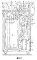
- the individual device parts to be described in more detail are mounted on a device frame 40 equipped with transport rollers.
- the frame 40 is closed at least in places by a panel 40 '.
- the device consists essentially of the shut-off valves VI to V8, which are equipped on the inlet and outlet sides with self-locking connections for receiving hoses, the pumps P1 and P2, a conductivity meter 17, a pressure meter 19, an ultrafilter 20, at least three sterile filters 13, 39 , 18, a mixing container 15, a balance 26 and a control and regulating device 27.
- the mixing container 15 is freely suspended and oscillating via two universal joints 24 and a yoke 25 and the upper-walled scale 26 is loaded.
- the scale 26 is arranged on the base of the frame, the mixing container 15 can of course also stand on the scale 26.
- other conventional force transducers can also serve as gravimetric sensors.
- the concentrate reservoir 9 for the electrolyte concentrate hangs, for example, on a gallows of the frame 40 and the container outlet opens into the connection 1 of the shut-off valve V1.
- An electric motor driven pump P1 is arranged between the concentrate reservoir 9 and valve 1 and conveys concentrate into the inlet 11 of the Mixing container 15.
- a connection to a high-purity water reservoir, not shown, is provided via a hose.
- the output of the valve V3 passes into a cross-shaped flow divider 12, the two outlets of which open into the two shut-off valves V2 or its liquid connection 2 and into the shut-off valve V4 or liquid connection 4.
- the third outlet of the flow divider 12 opens on the inlet side 13 'of a first sterile filter 13 of 0.2 ⁇ m pore size, which retains germs present in the ultrapure water and the outlet 13 "of the sterile filter 13 opens into a further inlet 14 of the mixing container 15, which for the better Mixing on the bottom of the container in a circle or spiral ends with a nozzle
- a second sterile filter 39 with a pore size of 0.2 ⁇ m is arranged between the shut-off valve V2 and the flow divider 12.
- An outlet 16 of the mixing container 15 opens into an electrical conductivity meter 17, which measures the electrical conductivity of the liquid in the mixing container 15, which is dependent on the current concentration of the liquid.
- the output of the concentration meter 17 opens into a T-shaped flow divider 7, which forms a bypass with the liquid connection 6 and the shut-off valve V6.
- a feed pump P2 the flow divider 7, the shut-off valve V7 and a liquid pressure meter 19 are arranged.
- the liquid flows directly or indirectly through these components.
- the outlet 22 on the cloudy side of the ultrafilter 20 also opens in a further inlet 8 of the mixing container 15 with the interposition of a further shut-off valve V8 in a circular shape on the container bottom.
- the clean-side outlet 23 of the ultrafilter 20 opens into the shut-off valve V5 and the liquid connection 5.
- This connection 5 is used for the direct forwarding of the prepared infusion solution for filling into a container for intermediate storage or directly to the consumer or consumers, that is with the interposition of the dialysis machines or hemofiltration machines the kidney patients.
- the electrical control and regulating device 27 has several alpha-numerical displays 28 in digital form as well as an input keyboard 29, control lamps 30 and a circuit diagram film 31 or imprint, which is explained in more detail in FIG. 2.
- the electrical device parts of the balance 26, the control and regulating device 27, the two pumps P1 and P2, the shut-off valves V1 to V8, the conductivity meter 17 and the pressure meter 19 contact each other with the aid of electrical lines 32, 33 and 34 and are via a mains connector 36 connected to the power grid or connectable.
- the control and regulating device 27 also has a plurality of function switches 35.
- the commercial scale 26 shown is equipped with a microprocessor and is communicatively connected to the control and regulating device 27 via a data output 37.
- the device can be permanently connected to a ultrapure water inlet with V3.
- the device for mixing the infusion solution Before starting up the device for mixing the infusion solution, it must be sterilized and rinsed free of the sterilizing agent.
- Chemical sterilization with formalin or hot sterilization can be carried out.
- the chemical sterilizing agent is introduced into the liquid connection 1 in a concentrated form, all other valves being closed.
- the concentrated sterilizing agent is diluted with ultrapure water in the mixing container according to the mixing ratio entered.
- VI is connected to V2 and V4 is connected to V5 using a short hose connector.
- the entire line system is self-contained and all liquid-carrying components can be chemically disinfected by switching the valves and pumps accordingly.
- a clock built into the device shows the duration of the disinfection.
- the disinfectant is discarded via the bypass 6.
- the entire pipe system is flushed with ultrapure water from disinfectant residues by switching the valves accordingly. The number of rinsing cycles is displayed.
- the mixing container 15 holds about 50 liters of liquid. To produce a certain amount of infusion solution, 1. the desired volumetric mixing ratio (concentrate / ultrapure water), 2. the spec. Weight of the concentrate (the specific weight of the ultrapure water is automatically set at 1 gr / ml by the computer) and 3. the total amount of the solution to be prepared is entered into the device.
- the computer uses the spec. Weight of the concentrate automatically calculates the gravimetric mixing ratio.
- the calculated amount of concentrate is metered into the empty mixing container 15 by the pump PI.
- the pump Pl stops. In the idle state, the concentrate weight is exactly determined by weighing. If there are differences between the target and actual weight of the concentrate, the amount of ultrapure water to be pumped is recalculated according to the actual concentrate weight. In this way, an exact setting of the mixing ratio is guaranteed.
- V3 opens and the ultrapure water flows via V3, sterile filter 13 through an immersion tube 14 'into the mixing tank 15.
- the immersion tube 14' is designed such that a circular swirling and thus homogeneous mixing of the solution takes place in the mixing vessel 15. If the calculated amount has flowed into the mixing vessel 15, V3 closes. Then pump P2 starts and V8 opens (all other valves are closed). This achieves additional mixing of the infusion solution, the turbid side of the ultrafilter 20 is freed of air, and the surface of the ultrafilter 20 is cleaned. This concludes the mixing program.
- the amount of infusion solution that is to be filled into a control bag can be entered via the input keyboard 29.
- This amount is removed from the mixing container 15 by the pump P2, with a conductivity meter 27 checked for exact concentration and filled accordingly by the pyrogen filter and by V5 into a container. If the conductivity deviates from the setpoint, V5 closes and the solution is discarded via the bypass. The discarded quantity is not added to the filled quantity.
- the device has another special program to protect it from germs during a longer withdrawal pause (no withdrawal of infusion solution).
- V4 is connected to V5 by means of a hose connection.
- Pump P2 maintains a liquid flow which recirculates from the mixing container 15 via pump P2, pyrogen filter 20, V5, V4, sterile filter 13 back into the mixing container 15.
- the clean-side outlet 23, V5 of the pyrogen-retaining ultrafilter 20 can be connected to the inlet 14 of the mixing container 15, preferably to the upstream inlet V4, 13 'of the sterile filter 13, and the processed infusion solution in a device-internal recirculation circuit from the feed pump P2 Mixing container 15 can be moved via the ultrafilter 20, sterile filter 13 and back into the mixing container 15.
- the outlet 22 of the ultrafilter 20 on the turbid side is included in the recirculation circuit maintained by the feed pump P2 in the bypass ultrafilter / mixing container.
- a ventilation filter 18 is also provided, which is placed on a further outlet 10 of the mixing container 15.
- the operating and display elements of the control and regulating device 27 are integrated into the cladding, as is the circuit diagram film 31, which visually indicates the current switching state of the device in the individual switching phases by electrical lamps and is shown in more detail in FIG. 2. is.
- the circuit diagram is printed on a foil. recorded directly on the device casing.
- housing openings are arranged in which small signal lamps are fastened which contact the control and regulating device 27 and display the respective switching status by their on or off status.
- these signal lamps are denoted by 38.30.
- the operating personnel have the possibility of optically following the current program sequence, the control of the valves and the other electrical structural units and immediately recognizing any errors or failures.
Abstract
Description
Die Erfindung betrifft ein Gerät zur Aufbereitung medizinischer Infusionslösungen. Neben der Haemodialyse hat sich in den letzten Jahren die Haemofiltration als Behandlungsmethode bei akutem und chronischem Nierenversagen immer mehr durchgesetzt. Zum Stand der Technik wird hingewiesen auf GB-PS 1 563 840, US-PS 3,579,441,GB-PS 1 366 086, GB-PS 1 555 389, US-PS 4,219,422. Dabei werden dem Patienten durch Filtration die sich im Blut angehäuften Schadstoffe und ein erhebliches Maß Blutflüssigkeit entzogen. Die Schadstoffe und Flüssigkeit werden verworfen. Zumindest ein Teil der Flüssigkeit muß dem Patienten in Form von Infusionslösungen wieder zugeführt werden. Diese Infusionslösungen werden zum direkten Verbrauch in handelsüblichen Gebinden, steril verpackt und sterilisiert geliefert und direkt über die Dialysemaschinen oder Haemofiltrationsmaschinen dem Patienten während der Behandlung zugeführt. Wegen der erheblichen Mengen, die jeder Patient benötigt, ist diese Handelsform der Infusionslösung unter wirtschaftlichen Gesichtspunkten unbefriedigend. Hinzu kommt, daß durch längere Lagerung die Gefahr einer Verkeimung der Lösung besteht und damit der Patient einem höheren Risiko ausgesetzt ist. Da in Kliniken und Dialysezentren eine größere Anzahl solcher "künstlicher Nieren" vorhanden sind, ist daher der Bedarf an Infusionslösung sehr groß. Auch bei der medizinischen Behandlung nierenerkrankter Patienten nach dem Prinzip der Dialyse, besonders aber bei der Peritonealdialyse, werden ebenfalls keimfreie, unter medizinischen Gesichtspunkten besonders zusammengesetzte Infusionslösungen bzw. Behandlungslösungen benötigt.The invention relates to a device for processing medical infusion solutions. In addition to hemodialysis, haemofiltration has become increasingly popular as a treatment for acute and chronic kidney failure in recent years. With regard to the prior art, reference is made to GB-PS 1 563 840, US-PS 3,579,441, GB-PS 1 366 086, GB-PS 1 555 389, US-PS 4,219,422. Filtration removes the pollutants accumulated in the blood and a considerable amount of blood fluid. The pollutants and liquid are discarded. At least part of the liquid must be returned to the patient in the form of infusion solutions. These infusion solutions are supplied for direct consumption in standard containers, sterile packed and sterilized and delivered directly via dialysis machines or haemofiltration machines fed to the patient during the treatment. Because of the considerable amounts that each patient needs, this commercial form of the infusion solution is economically unsatisfactory. In addition, there is a risk of the solution becoming contaminated by prolonged storage and the patient is thus at a higher risk. Since there are a large number of such "artificial kidneys" in clinics and dialysis centers, the need for infusion solution is very high. Also in the medical treatment of patients with kidney disease according to the principle of dialysis, but especially in peritoneal dialysis, germ-free infusion solutions or treatment solutions, which are especially composed from a medical point of view, are also required.
Andererseits sind auch bereits Anlagen zur direkten Herstellung der Infusionslösung aus den einzelnen Bestandteilen bekannt, z.B. EP-A 1 0 042 939, die jedoch für den klinischen Betrieb zu ungenau arbeiten. Hinzu kommt, daß die bekannten Geräte keine Einrichtung besitzen, um eine Verkeimung der im Gerät aufbereiteten Infusionslösung zu verhindern, wenn keine permanente Entnahme der Infusionslösung erfolgt, sondern längere Entnahmepausen zu berücksichtigen sind.On the other hand, systems for the direct production of the infusion solution from the individual components are already known, e.g. EP-A 1 0 042 939, which however work too imprecisely for clinical operation. In addition, the known devices do not have a device to prevent the infusion solution prepared in the device from becoming contaminated if the infusion solution is not permanently withdrawn, but rather longer pauses in the withdrawal are to be taken into account.
Der Erfindung liegt daher die Aufgabe zugrunde, ein Gerät zu schaffen, welches in der Bedienung einfach und sicher aufgehaut ist und die Möglichkeit zuläßt, Infusionslösungen zur unmittelbaren Verwendung am Patienten in gewünschter exakter Konzentration und Zusammensetzung herzustellen und das eine Verkeimung der Infusionslösung im Gerät während längerer Entnahmepausen ausschließt.The invention is therefore based on the object to provide a device which is easy and safe to use and which allows the possibility of producing infusion solutions for immediate use in the patient in the desired exact concentration and composition and which prevents the infusion solution in the device from becoming contaminated for a longer period of time Excludes withdrawal breaks.
Diese Aufgabe wird durch die im Anspruch 1 angegebenen Merkmale gelöst. Vorteilhafte Weiterbildungen sind in den Unteransprüchen angegeben. Hierbei wurde geräteseitig berücksichtigt, daß in allen Kliniken und Dialysestationen bereits großtechnische Anlagen vorhanden sind, mit denen Reinstwasser auf einer zentralen, nach dem Prinzip der Umkehrosmose arbeitenden Wasserversorgungsanlage herstellbar und somit das für die Herstellung der Infusionslösung notwendige Reinstwasser in großer Menge vorrätig ist. Der bisher in den handelsüblichen Gebinden von fertiger Infusionslösung vorhandene Anteil an Reinstwasser braucht also nicht mehr gelagert und transportiert zu werden.This object is achieved by the features specified in claim 1. Advantageous further developments are specified in the subclaims. On the device side, it was taken into account that large-scale technical systems are already available in all clinics and dialysis stations, with which ultrapure water can be produced on a central water supply system working according to the principle of reverse osmosis, and thus the ultrapure water necessary for the production of the infusion solution is available in large quantities. The portion of ultrapure water previously available in the commercially available containers of finished infusion solution therefore no longer needs to be stored and transported.
Das erfindungsgemäße Gerät kann daher portabel ausgebildet sein und die Lagerhaltung beschränkt sich nur noch auf die relativ kleinen Mengen an Elektrolytkonzentrat zur Herstellung der Infusionslösung. Die auf dem Gerät hergestellte Infusionslösung kann daher praktisch kurz nach ihrer Herstellung In-Line dem Patienten über die Dialysemaschine oder die Haemofiltrationsmaschine zugeführt werden. Die zugeführte Lösung ist pyrogenfrei und keimfrei, auch wenn die dauernde Entnahme durch längere Entnahmepause (Nichtentnahme von Infusionslösung) unterbrochen war.The device according to the invention can therefore be designed to be portable and the storage is limited only to the relatively small amounts of electrolyte concentrate for producing the infusion solution. The infusion solution produced on the device can therefore be supplied to the patient practically shortly after its production in-line via the dialysis machine or the hemofiltration machine. The solution supplied is pyrogen-free and germ-free, even if the continuous withdrawal was interrupted by a longer withdrawal period (no withdrawal of the infusion solution).
Ein bevorzugtes Ausführungsbeispiel des Gerätes ist in der beiliegenden Zeichnung näher erläutert. Dabei zeigt:
- Fig. 1 das portable Gerätegestell mit den darin angeordneten einzelnen Geräteelementen in vereinfachter Darstellung und
- Fig. 2 eine auf der Gerätefrontseite angeordnete Schaltplanfolie.
- Fig. 1 shows the portable device frame with the individual device elements arranged therein in a simplified representation and
- Fig. 2 is a circuit diagram film arranged on the front of the device.
Die noch näher zu beschreibenden Einzelgeräteteile sind auf ein mit Transportrollen ausgerüstetes Gerätegestell 40 montiert. Das Gestell 40 ist zumindest stellenweise durch eine Verkleidung 40' geschlossen.The individual device parts to be described in more detail are mounted on a
Das Gerät besteht im wesentlichen aus den Absperrventilen VI bis V8, die einlaßseitig und auslaßseitig mit selbstsperrenden Anschlüssen zur Aufnahme von Schläuchen ausgestattet sind, den Pumpen P1 und P2, einem Leitfähigkeitsmesser 17, einem Druckmesser 19, einem Ultrafilter 20, mindestens drei Sterilfiltern 13,39,18, einem Mischbehälter 15, einer Waage 26 und einem Steuer- und Regelgerät 27.The device consists essentially of the shut-off valves VI to V8, which are equipped on the inlet and outlet sides with self-locking connections for receiving hoses, the pumps P1 and P2, a conductivity meter 17, a
Im dargestellten Ausführungsbeispiel ist der Mischbehälter 15 über zwei Kreuzgelenke 24 und ein Joch 25 freihängend und pendelnd und die oberschalige Waage 26 belastend, aufgehängt. Bei Anordnung der Waage 26 am Gestellboden kann der Mischbehälter 15 natürlich auch auf der Waage 26 stehen. Anstelle der Waage 26 können auch andere herkömmliche Kraftaufnehmer als gravimetrischer Meßwertgeber dienen.In the exemplary embodiment shown, the
Alle übrigen Geräteteile sind mittelbar oder unmittelbar am Gestell 40 durch Verschraubungen oder dergleichen festgelegt.All other device parts are directly or indirectly fixed to the
Der Konzentratvorratsbehälter 9 für das Elektrolytkonzentrat hängt z.B. an einem Galgen des Gestell 40 und der Behälterauslaß mündet im Anschluß 1 des Absperrventils V1. Eine elektromotorisch angetriebene Pumpe P1 ist zwischen dem Konzentratvorratsbehälter 9 und Ventil 1 angeordnet und fördert Konzentrat in den Einlaß 11 des Mischbehälters 15. An den Einlaß 3 des Absperrventils V3 ist über einen Schlauch die Verbindung mit einem nicht dargestellten Reinstwasserreservoir vorgesehen. Der Ausgang des Ventils V3 geht in einen kreuzförmigen Stromteiler 12 über, dessen zwei Auslässe in den beiden Absperrventilen V2 bzw. dessen Flüssigkeitsanschluß 2 und im Absperrventil V4 bzw. Flüssigkeitsanschluß 4 münden. Der dritte Auslaß des Stromteilers 12 mündet auf der Einlaßseite 13' eines ersten Sterilfilters 13 von 0,2 um Porengröße, der im Reinstwasser vorhandene Keime zurückhält und der Auslaß 13" des Sterilfilters 13 mündet in einem weiteren Einlaß 14 des Mischbehälters 15, der zur besseren Durchmischung auf dem Behälterboden kreis- oder spiralförmig mit einer Düse endet. Zwischen dem Absperrventil V2 und dem Stromteiler 12 ist ein zweiter Sterilfilter 39 mit 0,2 um Porengröße angeordnet.The concentrate reservoir 9 for the electrolyte concentrate hangs, for example, on a gallows of the
Ein Auslaß 16 des Mischbehälters 15 mündet in einem elektrischen Leitfähigkeitsmesser 17, der die elektrische Leitfähigkeit der Flüssigkeit im Mischbehälter 15 mißt, die abhängig von der aktuellen Konzentration der Flüssigkeit ist. Der Ausgang des Konzentrationsmessers 17 mündet in einem T-förmigen Stromteiler 7, der mit dem Flüssigkeitsanschluß 6 und dem Absperrventil V6 einen Bypass bildet. Weiterhin ist der Stromteiler 7 mit einem weiteren Absperrventil V7 und dem Einlaß 21 eines Ultrafilters 20 mit einer Pyrogene zurückhaltenden Membran mit einem Cut off von = 20000 Daltons verbunden. Zwischen dem Einlaß 21 und des Ultrafilters 20 und dem Auslaß 16 des Mischbehälters 15 sind weiterhin der bereits erwähnte Leitfähigkeitsmesser 17, eine Förderpumpe P2, der Stromteiler 7, das Absperrventil V7 und ein Flüssigkeitsdruckmesser 19 angeordnet. Je nach Ausführungsform werden diese Bauteile mittelbar oder unmittelbar von der Flüssigkeit durchströmt. Der trübseitige Auslaß 22 des Ultrafilters 20 mündet unter Zwischenschaltung eines weiteren Absperrventiles V8 in einem weiteren Einlaß 8 des Mischbehälters 15 gleichfalls in einer Kreisform am Behälterboden. Der reinseitige Auslaß 23 des Ultrafilters 20 mündet in dem Absperrventil V5 und dem Flüssigkeitsanschluß 5. Dieser Anschluß 5 dient zur direkten Weiterleitung der aufbereiteten Infusionslösung zur Abfüllung in einen Behälter zur Zwischenlagerung oder direkt an den oder die Verbraucher, das sind unter Zwischenschaltung der Dialysemaschinen oder Haemofiltrationsmaschinen die nierenerkrankten Patienten.An
Das elektrische Steuer- und Regelgerät 27 weist mehrere alpha-numerische Anzeigen 28 in digitaler Form sowie eine Eingabetastatur 29, Kontrollampen 30 und eine Schaltplanfolie 31 oder Aufdruck auf, die in Fig. 2 näher erläutert ist. Die elektrischen Geräteteile der Waage 26, des Steuer-und Regelgerätes 27, der beiden Pumpen P1 und P2, der Absperrventile V1 bis V8, des Leitfähigkeitsmessers 17 und des Druckmessers 19 kontaktieren untereinander mit Hilfe elektrischer Leitungen 32,33 und 34 und sind über einen Netzanschlußstecker 36 an das Stromnetz angeschlossen bzw. anschließbar. Das Steuer- und Regelgerät 27 weist weiterhin mehrere Funktions-schalter 35 auf. Die'dargestellte handelsübliche Waage 26 ist mit einem Mikroprozessor ausgestattet und ist über einen Datenausgang 37 mit dem Steuer- und Regelgerät 27 kommunizierend verbunden.The electrical control and regulating
Das Gerät kann permanent mit V3 an einen Reinstwassereingang angeschlossen werden.The device can be permanently connected to a ultrapure water inlet with V3.
Vor Inbetriebnahme des Gerätes zur Mischung der Infusionslösung muß dieses sterilisiert und vom Sterilisierungsmittel freigespült werden. Hierbei kann eine chemische Sterilisation mit Formalin oder eine Heißsterilisation erfolgen. Zu diesem Zweck wird das chemische Sterilisationsmittel in konzentrierter Form in den Flüssigkeitsanschluß 1 eingeleitet, wobei alle anderen Ventile geschlossen sind. Das konzentrierte Sterilisationsmittel wird gemäß dem eingegebenen Mischungsverhältnis mit Reinstwasser im Mischbehälter verdünnt.Before starting up the device for mixing the infusion solution, it must be sterilized and rinsed free of the sterilizing agent. Chemical sterilization with formalin or hot sterilization can be carried out. For this purpose, the chemical sterilizing agent is introduced into the liquid connection 1 in a concentrated form, all other valves being closed. The concentrated sterilizing agent is diluted with ultrapure water in the mixing container according to the mixing ratio entered.
VI wird mit V2 und V4 wird mit V5 mittels eines kurzen Schlauchverbindungsstückes verbunden. So ist das gesamte Leitungssystem in sich geschlossen und sämtliche flüssigkeitführenden Baugruppen können durch entsprechende Schaltung der Ventile und Pumpen chemisch desinfiziert werden. Eine im Gerät eingebaute Uhr zeigt die Dauer der Desinfektion an.VI is connected to V2 and V4 is connected to V5 using a short hose connector. The entire line system is self-contained and all liquid-carrying components can be chemically disinfected by switching the valves and pumps accordingly. A clock built into the device shows the duration of the disinfection.
Nach vollendeter Desinfektion wird das Desinfektionsmittel über den Bypass 6 verworfen. Das gesamte Leitungssystem wird mit Reinstwasser von Desinfektionsmittelresten durch entsprechende Schaltung der Ventile freigespült. Die Anzahl der Spülzyklen wird angezeigt.After disinfection is complete, the disinfectant is discarded via the
Der Mischbehälter 15 faßt etwa 50 1 Flüssigkeit. Zur Herstellung von einer bestimmten Menge Infusionslösung wird 1. das gewünschte volumetrische Mischungsverhältnis (Konzentrat/Reinstwasser), 2. das spez. Gewicht des Konzentrats (das spez. Gewicht des Reinstwasser wird vom Rechner automatisch mit 1 gr/ml angesetzt) und 3. die Gesamtmenge der herzustellenden Lösung in das Gerät eingegeben.The mixing
Daraufhin wird evtl. im Gerät befindliche Flüssigkeit über den Bypass 6 entleert.Thereupon any liquid in the device is emptied via the
Da das Mischungsverhältnis, wie in der Dialyse üblich, volumetrisch eingegeben wurde, wird vom Rechner mit Hilfe des spez. Gewichtes des Konzentrates automatisch das gravimetrische Mischungsverhältnis berechnet. Die berechnete Konzentratmenge wird von der Pumpe PI in den leeren Mischbehälter 15 dosiert. Bei Erreichen des Sollgewichtes stoppt die Pumpe Pl. Im Ruhezustand wird das Konzentratgewicht durch eine Wägung exakt bestimmt. Bestehen Differenzen zwischen Soll- und Istgewicht des Konzentrates, so wird die zu fördernde Reinstwassermenge entsprechend dem Ist-Konzentratgewicht neu berechnet. Auf diese Art ist eine exakte Einstellung des Mischungsverhältnisses gewährleistet. Dann öffnet V3 und das Reinstwasser strömt via V3, Sterilfilter 13 durch ein Tauchrohr 14' in den Mischbehälter 15. Das Tauchrohr 14' ist so ausgebildet, daß im Mischgefäß 15 eine kreisförmige Verwirbelung und damit eine homogene Vermischung der Lösung erfolgt. Ist die berechnete Menge in das Mischgefäß 15 geflossen, schließt V3. Dann startet die Pumpe P2 und V8 wird geöffnet (alle anderen Ventile sind geschlossen). Hierdurch wird eine zusätzliche Vermischung der Infusionslösung erreicht, die Trübseite des Ultrafilters 20 wird von Luft befreit, und die Oberfläche des Ultrafilters 20 wird gereinigt. Damit ist das Mischprogramm beendet.Since the mixing ratio, as usual in dialysis, was entered volumetrically, the computer uses the spec. Weight of the concentrate automatically calculates the gravimetric mixing ratio. The calculated amount of concentrate is metered into the
Jetzt kann über die Eingabetastatur 29 die Infusionslösungsmenge eingegeben werden, die z.B. in einen Kontrollbeutel abgefüllt werden soll. Diese Menge wird aus dem Mischbehälter 15 durch die Pumpe P2 abgefördert, mit einem Leitfähigkeitsmesser 27 auf exakte Konzentration überprüft und durch das Pyrogenfilter entsprechend und durch V5 in ein Behältnis abgefüllt. Bei Abweichung der Leitfähigkeit vom Sollwert schließt V5 und die Lösung wird über den Bypass verworfen. Die verworfene Menge wird zur abgefüllten Menge nicht hinzugezählt.Now the amount of infusion solution that is to be filled into a control bag, for example, can be entered via the
Zum Schutz vor Verkeimung während einer längeren Entnahmepause (Nichtentnahme von Infusionslösung) besitzt das Gerät ein weiteres spezielles Programm. Zu diesem Zweck wird V4 mit V5 mittels einer Schlauchverbindung verbunden. Pumpe P2 hält einen Flüssigkeitsstrom, der vom Mischbehälter 15 über Pumpe P2, Pyrogenfilter 20, V5, V4, Sterilfilter 13 zurück in den Mischbehälter 15 rezirkuliert, aufrecht. Dies bedeutet, daß der reinseitige Auslaß 23,V5 des Pyrogene zurückhaltenden Ultrafilters 20 mit dem Einlaß 14 des Mischbehälters 15, vorzugsweise mit dem vorgelagerten Einlaß V4, 13' des Sterilfilters 13 verbindbar ist und durch die Förderpumpe P2 die aufbereitete Infusionslösung in einem geräteinternen Rezirkulationskreislauf vom Mischbehälter 15 über den Ultrafilter 20, Sterilfilter 13 und zurück in den Mischbehälter 15 bewegbar ist. Der trübseitige Auslaß 22 des Ultrafilters 20 ist dabei in den von der Förderpumpe P2 aufrechterhaltenen Rezirkulationskreislauf im Nebenschluß Ultrafilter/Mischbehälter einbezogen.The device has another special program to protect it from germs during a longer withdrawal pause (no withdrawal of infusion solution). For this purpose, V4 is connected to V5 by means of a hose connection. Pump P2 maintains a liquid flow which recirculates from the mixing
Zur sterilen Belüftung und Entlüftung des Mischbehälters 15 ist außerdem ein Belüftungsfilter 18 vorgesehen, der auf einen weiteren Auslaß 10 des Mischbehälters 15 aufgesetzt ist.For sterile ventilation and venting of the mixing
Die Bedienungs- und Anzeigeelemente des Steuer- und Regelgerätes 27 sind in die Verkleidung integriert ebenso die Schaltplanfolie 31, die durch elektrische Lampen den aktuellen Schaltzustand des Gerätes in den einzelnen Schaltphasen optisch anzeigt und in Fig. 2 näher dargestellt. ist. Der Schaltplan ist auf einer Folie aufgedruckt hzw. direkt auf der Geräteverkleidung aufgezeichnet. Unmittelbar neben den Symbolen für die vom Steuer-und Regelgerät 27 beeinflußbaren elektrischen Geräteteilen, das sind die beiden Pumpen P1 und P2 und die Absperrventile VI bis V8 sind Gehäusedurchbrechungen angeordnet, in denen kleine Signallampen befestigt sind, die das Steuer- und Regelgerät 27 kontaktieren und den jeweiligen Schaltzustand durch ihren ein- bzw. ausgeschalteten Zustand anzeigen. In Fig. 2 sind diese Signallampen einheitlich mit 38,30 bezeichnet. Das Bedienungspersonal hat aufgrund dieser vorteilhaften Ausgestaltung die Möglichkeit, den aktuellen Programmablauf, die Steuerung der Ventile und der anderen elektrischen Baueinheiten optisch zu verfolgen und eventuelle Fehler oder Ausfälle sofort zu erkennen.The operating and display elements of the control and regulating
Claims (11)
Applications Claiming Priority (3)
| Application Number | Priority Date | Filing Date | Title |
|---|---|---|---|
| DE3307112 | 1983-03-01 | ||
| DE8305707 | 1983-03-01 | ||
| DE19843407147 DE3407147A1 (en) | 1983-03-01 | 1984-02-28 | DEVICE FOR PROCESSING MEDICAL INFUSION SOLUTIONS |
Publications (2)
| Publication Number | Publication Date |
|---|---|
| EP0121085A1 true EP0121085A1 (en) | 1984-10-10 |
| EP0121085B1 EP0121085B1 (en) | 1986-09-10 |
Family
ID=25818883
Family Applications (1)
| Application Number | Title | Priority Date | Filing Date |
|---|---|---|---|
| EP84101994A Expired EP0121085B1 (en) | 1983-03-01 | 1984-02-25 | Apparatus for the preparation of medical infusion solutions |
Country Status (6)
| Country | Link |
|---|---|
| EP (1) | EP0121085B1 (en) |
| JP (1) | JPS59166156A (en) |
| AT (1) | ATE22013T1 (en) |
| DE (1) | DE3407147A1 (en) |
| ES (1) | ES530200A0 (en) |
| GB (1) | GB2135598B (en) |
Cited By (27)
| Publication number | Priority date | Publication date | Assignee | Title |
|---|---|---|---|---|
| EP0544839A1 (en) * | 1990-08-20 | 1993-06-09 | Abbott Laboratories | Medical drug formulation and delivery system |
| EP0622087A1 (en) * | 1993-04-27 | 1994-11-02 | Hospal Industrie | Process and device for injecting a sterile and pyrogenfree fluid obtained by filtration |
| FR2723002A1 (en) * | 1994-07-26 | 1996-02-02 | Hospal Ind | DEVICE AND METHOD FOR PREPARING A FILTRATION PROCESSING LIQUID |
| WO1997007837A1 (en) * | 1995-08-30 | 1997-03-06 | Baxter International Inc. | System and method for providing sterile fluids for admixed solutions in automated peritoneal dialysis |
| WO2005077335A1 (en) * | 2004-02-03 | 2005-08-25 | Baxter International Inc. | Intravenous solution producing systems and methods |
| US7981281B2 (en) | 2008-07-09 | 2011-07-19 | Baxter International, Inc. | Dialysis system having regimen generation methodology |
| US8057679B2 (en) | 2008-07-09 | 2011-11-15 | Baxter International Inc. | Dialysis system having trending and alert generation |
| US8062513B2 (en) | 2008-07-09 | 2011-11-22 | Baxter International Inc. | Dialysis system and machine having therapy prescription recall |
| US8168063B2 (en) | 2008-07-09 | 2012-05-01 | Baxter International Inc. | Dialysis system having filtering method for determining therapy prescriptions |
| WO2014105267A1 (en) | 2012-12-24 | 2014-07-03 | Fresenius Medical Care Holdings, Inc. | Load suspension and weighing system for a dialysis machine reservoir |
| US10019020B2 (en) | 2013-11-11 | 2018-07-10 | Fresenius Medical Care Holdings, Inc. | Smart actuator for valve |
| US10022673B2 (en) | 2007-09-25 | 2018-07-17 | Fresenius Medical Care Holdings, Inc. | Manifolds for use in conducting dialysis |
| US10034973B2 (en) | 2007-11-29 | 2018-07-31 | Fresenius Medical Care Holdings, Inc. | Disposable apparatus and kit for conducting dialysis |
| US10130746B2 (en) | 2003-01-07 | 2018-11-20 | Nxstage Medical, Inc. | Filtration system for preparation of fluids for medical applications |
| US10197180B2 (en) | 2009-01-12 | 2019-02-05 | Fresenius Medical Care Holdings, Inc. | Valve system |
| US10258731B2 (en) | 2007-09-13 | 2019-04-16 | Fresenius Medical Care Holdings, Inc. | Manifold diaphragms |
| US10314958B2 (en) | 2009-05-20 | 2019-06-11 | Baxter International Inc. | System and method for pairing a dialysis machine with peripheral devices |
| US10383993B2 (en) | 2007-09-13 | 2019-08-20 | Fresenius Medical Care Holdings, Inc. | Pump shoe for use in a pumping system of a dialysis machine |
| US10420871B2 (en) | 2003-01-07 | 2019-09-24 | Nxstage Medical, Inc. | Filtration system for preparation of fluids for medical applications |
| CN110582308A (en) * | 2017-05-05 | 2019-12-17 | 甘布罗伦迪亚股份公司 | System and method for producing microbial controlled fluids |
| US10561780B2 (en) | 2008-07-09 | 2020-02-18 | Baxter International Inc. | Dialysis system having inventory management including online dextrose mixing |
| US10596310B2 (en) | 2007-09-13 | 2020-03-24 | Fresenius Medical Care Holdings, Inc. | Portable dialysis machine |
| US10670577B2 (en) | 2008-10-30 | 2020-06-02 | Fresenius Medical Care Holdings, Inc. | Modular reservoir assembly for a hemodialysis and hemofiltration system |
| US10758662B2 (en) | 2007-11-29 | 2020-09-01 | Fresenius Medical Care Holdings, Inc. | Priming system and method for dialysis systems |
| US10758868B2 (en) | 2008-10-30 | 2020-09-01 | Fresenius Medical Care Holdings, Inc. | Methods and systems for leak detection in a dialysis system |
| US10973969B2 (en) | 2005-01-07 | 2021-04-13 | Nxstage Medical, Inc. | Filtration system for preparation of fluids for medical applications |
| US11525798B2 (en) | 2012-12-21 | 2022-12-13 | Fresenius Medical Care Holdings, Inc. | Method and system of monitoring electrolyte levels and composition using capacitance or induction |
Families Citing this family (26)
| Publication number | Priority date | Publication date | Assignee | Title |
|---|---|---|---|---|
| DE3443911C2 (en) | 1984-12-01 | 1994-06-01 | Andreas Alexander Dr Med Mund | Device for the production of liquid concentrate from powdered concentrate salt for the preparation of dialysis fluid |
| DE3448502C2 (en) * | 1984-12-01 | 1998-10-22 | Fresenius Ag | Method and device for producing a dialysis fluid |
| DE3448262C2 (en) * | 1984-12-07 | 1990-06-21 | Fresenius Ag, 6380 Bad Homburg, De | Method of testing sterilising filters of a haemodial filtration apparatus |
| DE3444671A1 (en) * | 1984-12-07 | 1986-06-12 | Fresenius AG, 6380 Bad Homburg | HAEMODIA FILTRATION DEVICE |
| JPS62170257A (en) * | 1986-01-21 | 1987-07-27 | 川澄化学工業株式会社 | Production of dyalysate |
| US4857181A (en) * | 1986-10-30 | 1989-08-15 | Cobe Laboratories, Inc. | Control of cleaning of dialysate preparation apparatus |
| DE3641843A1 (en) * | 1986-12-08 | 1988-06-16 | Fresenius Ag | HAEMODIALYSIS DEVICE WITH STERILIZER |
| JPH02283374A (en) * | 1989-04-25 | 1990-11-20 | Saitetsuku Kk | Apparatus and method for feeding dialyzate |
| US5178603A (en) * | 1990-07-24 | 1993-01-12 | Baxter International, Inc. | Blood extraction and reinfusion flow control system and method |
| JP3427449B2 (en) * | 1993-10-20 | 2003-07-14 | ニプロ株式会社 | Dissolution equipment for dialysate drug |
| DE29612534U1 (en) * | 1996-07-19 | 1997-11-13 | Braun Melsungen Ag | Infusion set |
| DE19640841A1 (en) * | 1996-10-02 | 1998-05-14 | Fresenius Medical Care De Gmbh | Preparation of ultra-pure infusion or dialysis solution |
| DE19924513C1 (en) * | 1999-05-28 | 2000-08-10 | Wolfgang Kahn | Equipment preparing concentrated salt solution for dialysis comprises vessel with recirculation pump and flushing spray, with control system executing filling, mixing and rinsing sequences. |
| GB2362843A (en) * | 2000-06-03 | 2001-12-05 | Kuo Hsin Ho & Fed Medical Co L | Mixing concentrates and water in haemodialysis |
| EP1399193B1 (en) * | 2001-02-16 | 2014-01-08 | Piedmont Renal Clinics, P.A. | Automated peritoneal dialysis system and process with in-line sterilization of dialysate |
| WO2003103533A2 (en) | 2002-06-06 | 2003-12-18 | Nxstage Medical, Inc. | Last-chance quality check and/or air/pyrogen filter for infusion systems |
| DE602006017654D1 (en) * | 2005-01-07 | 2010-12-02 | Nxstage Medical Inc | FILTRATION SYSTEM FOR THE MANUFACTURE OF LIQUIDS FOR MEDICAL APPLICATIONS |
| US8469331B2 (en) | 2006-04-07 | 2013-06-25 | Nxstage Medical, Inc. | Filtration system for preparation of fluids for medical applications |
| US20100051552A1 (en) * | 2008-08-28 | 2010-03-04 | Baxter International Inc. | In-line sensors for dialysis applications |
| US8926551B2 (en) | 2009-07-07 | 2015-01-06 | Baxter Healthcare Inc. | Peritoneal dialysis therapy with large dialysis solution volumes |
| JP5736661B2 (en) * | 2010-04-09 | 2015-06-17 | ニプロ株式会社 | Contamination prevention method in dialysis piping |
| JP6049685B2 (en) | 2011-03-23 | 2016-12-21 | ネクステージ メディカル インコーポレイテッド | Peritoneal dialysis disposable unit, controller, peritoneal dialysis system |
| US20130146541A1 (en) | 2011-12-13 | 2013-06-13 | Nxstage Medical, Inc. | Fluid purification methods, devices, and systems |
| US11338074B2 (en) | 2013-03-14 | 2022-05-24 | Baxter International Inc. | System and method for electronic identification of remote peritoneal dialysis exchanges |
| CN109172900B (en) | 2013-03-14 | 2021-06-04 | 贝克斯特国际公司 | System and method for peritoneal dialysis exchange with reusable energy supply unit |
| JP2021516089A (en) | 2018-02-28 | 2021-07-01 | ネクステージ メディカル インコーポレイテッド | Fluid preparation and treatment equipment, methods, and systems |
Citations (11)
| Publication number | Priority date | Publication date | Assignee | Title |
|---|---|---|---|---|
| DE2734075A1 (en) * | 1976-07-30 | 1978-02-09 | Inst Nat Sante Rech Med | HAEMODIALYSIS METHOD AND EQUIPMENT |
| US4153554A (en) * | 1977-02-22 | 1979-05-08 | American Micro-Bionics Corp. | Apparatus for use in artificial kidney system |
| EP0004600A2 (en) * | 1978-03-22 | 1979-10-17 | Hoechst Aktiengesellschaft | Peristaltic pump for a dialysis solution |
| EP0042939A1 (en) * | 1980-06-27 | 1982-01-06 | Gambro Lundia AB | Hemofiltration system |
| DE3121098A1 (en) * | 1980-05-28 | 1982-03-25 | Instrumentarium Oy, 00510 Helsinki | PERITONEAL DIALYSIS DEVICE |
| DE3122756A1 (en) * | 1980-08-13 | 1982-06-09 | VEB Meßgerätewerk Zwönitz, DDR 9417 Zwönitz | Device for the extracorporeal treatment of blood, and method of controlling it |
| US4338190A (en) * | 1976-02-13 | 1982-07-06 | A. T. Ramot Plastics Ltd. | Peritoneal artificial kidney |
| GB2091126A (en) * | 1981-01-16 | 1982-07-28 | Italiana Farmaceutici Ravizza | Preparing a solution for peritoneal dialysis |
| DE3110022A1 (en) * | 1981-03-16 | 1982-10-07 | Dr. Eduard Fresenius, Chemisch-pharmazeutische Industrie KG, 6380 Bad Homburg | Device for preparing sterile liquids |
| EP0062148A1 (en) * | 1981-04-07 | 1982-10-13 | Laboratorien Hausmann AG | Device for continuous ambulatory peritoneal dialysis |
| US4370983A (en) * | 1971-01-20 | 1983-02-01 | Lichtenstein Eric Stefan | Computer-control medical care system |
Family Cites Families (2)
| Publication number | Priority date | Publication date | Assignee | Title |
|---|---|---|---|---|
| US3753493A (en) * | 1971-04-23 | 1973-08-21 | E Mellor | Artificial kidney cleaning apparatus |
| GB2063704A (en) * | 1979-12-05 | 1981-06-10 | Tecmed Eng Ltd | Dialysis unit |
-
1984
- 1984-02-25 AT AT8484101994T patent/ATE22013T1/en active
- 1984-02-25 EP EP84101994A patent/EP0121085B1/en not_active Expired
- 1984-02-28 DE DE19843407147 patent/DE3407147A1/en not_active Withdrawn
- 1984-02-29 JP JP59036347A patent/JPS59166156A/en active Granted
- 1984-03-01 ES ES530200A patent/ES530200A0/en active Granted
- 1984-03-01 GB GB08405378A patent/GB2135598B/en not_active Expired
Patent Citations (11)
| Publication number | Priority date | Publication date | Assignee | Title |
|---|---|---|---|---|
| US4370983A (en) * | 1971-01-20 | 1983-02-01 | Lichtenstein Eric Stefan | Computer-control medical care system |
| US4338190A (en) * | 1976-02-13 | 1982-07-06 | A. T. Ramot Plastics Ltd. | Peritoneal artificial kidney |
| DE2734075A1 (en) * | 1976-07-30 | 1978-02-09 | Inst Nat Sante Rech Med | HAEMODIALYSIS METHOD AND EQUIPMENT |
| US4153554A (en) * | 1977-02-22 | 1979-05-08 | American Micro-Bionics Corp. | Apparatus for use in artificial kidney system |
| EP0004600A2 (en) * | 1978-03-22 | 1979-10-17 | Hoechst Aktiengesellschaft | Peristaltic pump for a dialysis solution |
| DE3121098A1 (en) * | 1980-05-28 | 1982-03-25 | Instrumentarium Oy, 00510 Helsinki | PERITONEAL DIALYSIS DEVICE |
| EP0042939A1 (en) * | 1980-06-27 | 1982-01-06 | Gambro Lundia AB | Hemofiltration system |
| DE3122756A1 (en) * | 1980-08-13 | 1982-06-09 | VEB Meßgerätewerk Zwönitz, DDR 9417 Zwönitz | Device for the extracorporeal treatment of blood, and method of controlling it |
| GB2091126A (en) * | 1981-01-16 | 1982-07-28 | Italiana Farmaceutici Ravizza | Preparing a solution for peritoneal dialysis |
| DE3110022A1 (en) * | 1981-03-16 | 1982-10-07 | Dr. Eduard Fresenius, Chemisch-pharmazeutische Industrie KG, 6380 Bad Homburg | Device for preparing sterile liquids |
| EP0062148A1 (en) * | 1981-04-07 | 1982-10-13 | Laboratorien Hausmann AG | Device for continuous ambulatory peritoneal dialysis |
Cited By (61)
| Publication number | Priority date | Publication date | Assignee | Title |
|---|---|---|---|---|
| EP0544839A4 (en) * | 1990-08-20 | 1993-08-11 | Abbott Laboratories | Medical drug formulation and delivery system |
| EP0544839A1 (en) * | 1990-08-20 | 1993-06-09 | Abbott Laboratories | Medical drug formulation and delivery system |
| EP0622087A1 (en) * | 1993-04-27 | 1994-11-02 | Hospal Industrie | Process and device for injecting a sterile and pyrogenfree fluid obtained by filtration |
| WO1994025085A1 (en) * | 1993-04-27 | 1994-11-10 | Hospal Industrie | Method and device for injecting a sterile apyrogen liquid obtained by filtration |
| US6039877A (en) * | 1994-07-26 | 2000-03-21 | Hospal Industrie | Device and method for preparing a treatment liquid by filtration |
| FR2723002A1 (en) * | 1994-07-26 | 1996-02-02 | Hospal Ind | DEVICE AND METHOD FOR PREPARING A FILTRATION PROCESSING LIQUID |
| EP0694312A3 (en) * | 1994-07-26 | 1996-03-13 | Hospal Ind | |
| US5702597A (en) * | 1994-07-26 | 1997-12-30 | Hospal Industrie | Device for preparing a treatment liquid by filtration |
| WO1997007837A1 (en) * | 1995-08-30 | 1997-03-06 | Baxter International Inc. | System and method for providing sterile fluids for admixed solutions in automated peritoneal dialysis |
| EP1277485A1 (en) * | 1995-08-30 | 2003-01-22 | Baxter International Inc. | System for infusion of a plurality of solutions to a peritoneal cavity of a patient |
| KR100446891B1 (en) * | 1995-08-30 | 2004-12-30 | 박스터 인터내쇼날 인코포레이티드 | Apparatus for providing sterile fluid as an automated peritoneal dialysis mixed solution |
| US10420871B2 (en) | 2003-01-07 | 2019-09-24 | Nxstage Medical, Inc. | Filtration system for preparation of fluids for medical applications |
| US11446417B2 (en) | 2003-01-07 | 2022-09-20 | Nxstage Medical, Inc. | Filtration system for preparation of fluids for medical applications |
| US10130746B2 (en) | 2003-01-07 | 2018-11-20 | Nxstage Medical, Inc. | Filtration system for preparation of fluids for medical applications |
| WO2005077335A1 (en) * | 2004-02-03 | 2005-08-25 | Baxter International Inc. | Intravenous solution producing systems and methods |
| US11896750B2 (en) | 2005-01-07 | 2024-02-13 | Nxstage Medical, Inc. | Filtration system for preparation of fluids for medical applications |
| US10973969B2 (en) | 2005-01-07 | 2021-04-13 | Nxstage Medical, Inc. | Filtration system for preparation of fluids for medical applications |
| US11318248B2 (en) | 2007-09-13 | 2022-05-03 | Fresenius Medical Care Holdings, Inc. | Methods for heating a reservoir unit in a dialysis system |
| US11071811B2 (en) | 2007-09-13 | 2021-07-27 | Fresenius Medical Care Holdings, Inc. | Portable dialysis machine |
| US10857281B2 (en) | 2007-09-13 | 2020-12-08 | Fresenius Medical Care Holdings, Inc. | Disposable kits adapted for use in a dialysis machine |
| US10258731B2 (en) | 2007-09-13 | 2019-04-16 | Fresenius Medical Care Holdings, Inc. | Manifold diaphragms |
| US10596310B2 (en) | 2007-09-13 | 2020-03-24 | Fresenius Medical Care Holdings, Inc. | Portable dialysis machine |
| US10383993B2 (en) | 2007-09-13 | 2019-08-20 | Fresenius Medical Care Holdings, Inc. | Pump shoe for use in a pumping system of a dialysis machine |
| US11224841B2 (en) | 2007-09-25 | 2022-01-18 | Fresenius Medical Care Holdings, Inc. | Integrated disposable component system for use in dialysis systems |
| US10022673B2 (en) | 2007-09-25 | 2018-07-17 | Fresenius Medical Care Holdings, Inc. | Manifolds for use in conducting dialysis |
| US11439738B2 (en) | 2007-11-29 | 2022-09-13 | Fresenius Medical Care Holdings, Inc. | Methods and Systems for fluid balancing in a dialysis system |
| US10758662B2 (en) | 2007-11-29 | 2020-09-01 | Fresenius Medical Care Holdings, Inc. | Priming system and method for dialysis systems |
| US10758661B2 (en) | 2007-11-29 | 2020-09-01 | Fresenius Medical Care Holdings, Inc. | Disposable apparatus and kit for conducting dialysis |
| US10034973B2 (en) | 2007-11-29 | 2018-07-31 | Fresenius Medical Care Holdings, Inc. | Disposable apparatus and kit for conducting dialysis |
| US8168063B2 (en) | 2008-07-09 | 2012-05-01 | Baxter International Inc. | Dialysis system having filtering method for determining therapy prescriptions |
| US9141760B2 (en) | 2008-07-09 | 2015-09-22 | Baxter International Inc. | System and method for selection of stored dialysis therapy prescriptions |
| US7981281B2 (en) | 2008-07-09 | 2011-07-19 | Baxter International, Inc. | Dialysis system having regimen generation methodology |
| US10265455B2 (en) | 2008-07-09 | 2019-04-23 | Baxter International Inc. | Dialysis system including wireless sensor data |
| US10272190B2 (en) | 2008-07-09 | 2019-04-30 | Baxter International Inc. | Renal therapy system including a blood pressure monitor |
| US10307524B2 (en) | 2008-07-09 | 2019-06-04 | Baxter International Inc. | Dialysis method and system including wireless patient data |
| US8057679B2 (en) | 2008-07-09 | 2011-11-15 | Baxter International Inc. | Dialysis system having trending and alert generation |
| US10016554B2 (en) | 2008-07-09 | 2018-07-10 | Baxter International Inc. | Dialysis system including wireless patient data |
| US9690905B2 (en) | 2008-07-09 | 2017-06-27 | Baxter International Inc. | Dialysis treatment prescription system and method |
| US8062513B2 (en) | 2008-07-09 | 2011-11-22 | Baxter International Inc. | Dialysis system and machine having therapy prescription recall |
| US8257582B2 (en) | 2008-07-09 | 2012-09-04 | Baxter International Inc. | Dialysis system and machine having therapy prescription recall |
| US10561780B2 (en) | 2008-07-09 | 2020-02-18 | Baxter International Inc. | Dialysis system having inventory management including online dextrose mixing |
| US8313642B2 (en) | 2008-07-09 | 2012-11-20 | Baxter International Inc. | Dialysis system including wireless patient data and trending and alert generation |
| US8512554B2 (en) | 2008-07-09 | 2013-08-20 | Baxter International Inc. | Dialysis system and machine having therapy prescription recall |
| US9149570B2 (en) | 2008-07-09 | 2015-10-06 | Baxter International Inc. | Dialysis system having filtering method for determining therapy prescriptions |
| US10758868B2 (en) | 2008-10-30 | 2020-09-01 | Fresenius Medical Care Holdings, Inc. | Methods and systems for leak detection in a dialysis system |
| US10670577B2 (en) | 2008-10-30 | 2020-06-02 | Fresenius Medical Care Holdings, Inc. | Modular reservoir assembly for a hemodialysis and hemofiltration system |
| US11169137B2 (en) | 2008-10-30 | 2021-11-09 | Fresenius Medical Care Holdings, Inc. | Modular reservoir assembly for a hemodialysis and hemofiltration system |
| US10808861B2 (en) | 2009-01-12 | 2020-10-20 | Fresenius Medical Care Holdings, Inc. | Valve system |
| US10197180B2 (en) | 2009-01-12 | 2019-02-05 | Fresenius Medical Care Holdings, Inc. | Valve system |
| US10314958B2 (en) | 2009-05-20 | 2019-06-11 | Baxter International Inc. | System and method for pairing a dialysis machine with peripheral devices |
| US11027053B2 (en) | 2009-05-20 | 2021-06-08 | Baxter International Inc. | Method for pairing a dialysis machine with peripheral devices |
| US11525798B2 (en) | 2012-12-21 | 2022-12-13 | Fresenius Medical Care Holdings, Inc. | Method and system of monitoring electrolyte levels and composition using capacitance or induction |
| WO2014105267A1 (en) | 2012-12-24 | 2014-07-03 | Fresenius Medical Care Holdings, Inc. | Load suspension and weighing system for a dialysis machine reservoir |
| KR102269049B1 (en) | 2012-12-24 | 2021-06-23 | 프레제니우스 메디칼 케어 홀딩스 인코퍼레이티드 | Load suspension and weighing system for a dialysis machine reservoir |
| US11187572B2 (en) | 2012-12-24 | 2021-11-30 | Fresenius Medical Care Holdings, Inc. | Dialysis systems with a suspended reservoir |
| EP2934661A4 (en) * | 2012-12-24 | 2016-08-03 | Fresenius Med Care Hldg Inc | Load suspension and weighing system for a dialysis machine reservoir |
| US10539450B2 (en) | 2012-12-24 | 2020-01-21 | Fresenius Medical Care Holdings, Inc. | Load suspension and weighing system for a dialysis machine reservoir |
| KR20150102038A (en) * | 2012-12-24 | 2015-09-04 | 프레제니우스 메디칼 케어 홀딩스 인코퍼레이티드 | Load suspension and weighing system for a dialysis machine reservoir |
| US10817004B2 (en) | 2013-11-11 | 2020-10-27 | Fresenius Medical Care Holdings, Inc. | Valve system with a pressure sensing displacement member |
| US10019020B2 (en) | 2013-11-11 | 2018-07-10 | Fresenius Medical Care Holdings, Inc. | Smart actuator for valve |
| CN110582308A (en) * | 2017-05-05 | 2019-12-17 | 甘布罗伦迪亚股份公司 | System and method for producing microbial controlled fluids |
Also Published As
| Publication number | Publication date |
|---|---|
| JPS59166156A (en) | 1984-09-19 |
| GB2135598B (en) | 1985-10-02 |
| DE3407147A1 (en) | 1984-09-06 |
| JPH0352296B2 (en) | 1991-08-09 |
| GB8405378D0 (en) | 1984-04-04 |
| ATE22013T1 (en) | 1986-09-15 |
| ES8500070A1 (en) | 1984-11-01 |
| GB2135598A (en) | 1984-09-05 |
| ES530200A0 (en) | 1984-11-01 |
| EP0121085B1 (en) | 1986-09-10 |
Similar Documents
| Publication | Publication Date | Title |
|---|---|---|
| EP0121085B1 (en) | Apparatus for the preparation of medical infusion solutions | |
| DE3307112C2 (en) | Device for the preparation of medical infusion solutions | |
| DE69938035T2 (en) | SAFETY DEVICE FOR DIALYSIS MACHINES AND METHOD FOR ACTIVATING THE SAFETY DEVICE | |
| EP0212127B1 (en) | Hemodiafiltration device | |
| DE112014001324B4 (en) | System and method for performing alternate and sequential blood and peritoneal dialysis modalities | |
| DE69530904T3 (en) | Method and device for the central production of a salt concentrate, method for disinfecting the device and use of a container in the device | |
| DE19655224B4 (en) | Home dialysis machine components and methods of operation - where the machine includes water treatment, dialysate preparation and disinfection systems in user friendly, efficient and affordable haemodialysis package | |
| EP1053759B1 (en) | Method for controlling a device for partial dialysate collection | |
| DE60007723T2 (en) | PIPING SYSTEM FOR EXTRACORPORAL BLOOD CLEANING AND USE THEREOF | |
| DE2838414C2 (en) | Device for hemodialysis and for withdrawing ultrafiltrate | |
| DE69629347T2 (en) | PORTABLE PUMPING APPARATUS FOR CONTINUOUS AMBULANT PERITONEAL DIALYSIS | |
| DE3204317C1 (en) | Cardioplegic control and regulating device | |
| EP2663346B1 (en) | Production of individualized concentrate | |
| DE2027087A1 (en) | Device for pentonaal dialysis | |
| DE2740062C3 (en) | Hemodialysis machine | |
| DE8305713U1 (en) | Device for the preparation of medical infusion solutions for the "artificial kidney" | |
| EP3238757A1 (en) | Device for extracorporeal blood treatment with concentrate change | |
| EP1110564A2 (en) | Apparatus for the peritoneal dialysis | |
| DE3132790A1 (en) | Artificial kidney | |
| DE19655227B4 (en) | Home dialysis machine components and methods of operation - where the machine includes water treatment, dialysate preparation and disinfection systems in user friendly, efficient and affordable haemodialysis package | |
| DE19702213A1 (en) | Apparatus for mixing liquids, especially for dialysis | |
| DE4133652A1 (en) | Continuous prepn. of satd. bi:carbonate soln. | |
| DE2924406A1 (en) | Charging bi:carbonate to dialysis liq. in haemodialysis appts. - by adding bi:carbonate and dialysis concentrate in series, avoids the pptn. of scale | |
| DE2629717A1 (en) | Blood dialyser mixture control system - has liq. collector vessels on balance arm with balance weight and weight monitor | |
| DE3046162A1 (en) | Blood dialysis unit with membrane filter - uses double pendulum piston pump to ensure separation of fresh and used dialysate |
Legal Events
| Date | Code | Title | Description |
|---|---|---|---|
| PUAI | Public reference made under article 153(3) epc to a published international application that has entered the european phase |
Free format text: ORIGINAL CODE: 0009012 |
|
| AK | Designated contracting states |
Designated state(s): AT CH DE FR IT LI NL SE |
|
| 17P | Request for examination filed |
Effective date: 19841106 |
|
| GRAA | (expected) grant |
Free format text: ORIGINAL CODE: 0009210 |
|
| PUAC | Information related to the publication of a b1 document modified or deleted |
Free format text: ORIGINAL CODE: 0009299EPPU |
|
| ITF | It: translation for a ep patent filed |
Owner name: DE DOMINICIS & MAYER S.R.L. |
|
| AK | Designated contracting states |
Kind code of ref document: B1 Designated state(s): AT CH DE FR IT LI NL SE |
|
| REF | Corresponds to: |
Ref document number: 22013 Country of ref document: AT Date of ref document: 19860915 Kind code of ref document: T |
|
| RB1 | B1 document published (corrected) |
Free format text: IST GEL!SCHT |
|
| REF | Corresponds to: |
Ref document number: 3460648 Country of ref document: DE Date of ref document: 19861016 |
|
| ET | Fr: translation filed | ||
| GRAA | (expected) grant |
Free format text: ORIGINAL CODE: 0009210 |
|
| AK | Designated contracting states |
Kind code of ref document: B1 Designated state(s): AT CH DE FR IT LI NL SE |
|
| REF | Corresponds to: |
Ref document number: 25585 Country of ref document: AT Date of ref document: 19870315 Kind code of ref document: T |
|
| EN | Fr: translation not filed |
Free format text: BO 44/86 PAGE 195: ANNULATION |
|
| ET | Fr: translation filed | ||
| PLBE | No opposition filed within time limit |
Free format text: ORIGINAL CODE: 0009261 |
|
| STAA | Information on the status of an ep patent application or granted ep patent |
Free format text: STATUS: NO OPPOSITION FILED WITHIN TIME LIMIT |
|
| 26N | No opposition filed | ||
| PGFP | Annual fee paid to national office [announced via postgrant information from national office to epo] |
Ref country code: FR Payment date: 19901227 Year of fee payment: 8 |
|
| PGFP | Annual fee paid to national office [announced via postgrant information from national office to epo] |
Ref country code: CH Payment date: 19901228 Year of fee payment: 8 |
|
| PGFP | Annual fee paid to national office [announced via postgrant information from national office to epo] |
Ref country code: SE Payment date: 19910215 Year of fee payment: 8 |
|
| PGFP | Annual fee paid to national office [announced via postgrant information from national office to epo] |
Ref country code: DE Payment date: 19910226 Year of fee payment: 8 |
|
| ITTA | It: last paid annual fee | ||
| PGFP | Annual fee paid to national office [announced via postgrant information from national office to epo] |
Ref country code: NL Payment date: 19910228 Year of fee payment: 8 Ref country code: AT Payment date: 19910228 Year of fee payment: 8 |
|
| PG25 | Lapsed in a contracting state [announced via postgrant information from national office to epo] |
Ref country code: AT Effective date: 19920225 |
|
| PG25 | Lapsed in a contracting state [announced via postgrant information from national office to epo] |
Ref country code: SE Effective date: 19920226 |
|
| PG25 | Lapsed in a contracting state [announced via postgrant information from national office to epo] |
Ref country code: LI Effective date: 19920229 Ref country code: CH Effective date: 19920229 |
|
| PG25 | Lapsed in a contracting state [announced via postgrant information from national office to epo] |
Ref country code: NL Effective date: 19920901 |
|
| NLV4 | Nl: lapsed or anulled due to non-payment of the annual fee | ||
| PG25 | Lapsed in a contracting state [announced via postgrant information from national office to epo] |
Ref country code: FR Effective date: 19921030 |
|
| REG | Reference to a national code |
Ref country code: CH Ref legal event code: PL |
|
| PG25 | Lapsed in a contracting state [announced via postgrant information from national office to epo] |
Ref country code: DE Effective date: 19921103 |
|
| REG | Reference to a national code |
Ref country code: FR Ref legal event code: ST |
|
| EUG | Se: european patent has lapsed |
Ref document number: 84101994.6 Effective date: 19920904 |