EP0120472A1 - Device for applying a foamed material - Google Patents
Device for applying a foamed material Download PDFInfo
- Publication number
- EP0120472A1 EP0120472A1 EP84103172A EP84103172A EP0120472A1 EP 0120472 A1 EP0120472 A1 EP 0120472A1 EP 84103172 A EP84103172 A EP 84103172A EP 84103172 A EP84103172 A EP 84103172A EP 0120472 A1 EP0120472 A1 EP 0120472A1
- Authority
- EP
- European Patent Office
- Prior art keywords
- foam
- applicator
- applicator according
- guide walls
- application device
- Prior art date
- Legal status (The legal status is an assumption and is not a legal conclusion. Google has not performed a legal analysis and makes no representation as to the accuracy of the status listed.)
- Withdrawn
Links
Images


Classifications
-
- D—TEXTILES; PAPER
- D06—TREATMENT OF TEXTILES OR THE LIKE; LAUNDERING; FLEXIBLE MATERIALS NOT OTHERWISE PROVIDED FOR
- D06B—TREATING TEXTILE MATERIALS USING LIQUIDS, GASES OR VAPOURS
- D06B19/00—Treatment of textile materials by liquids, gases or vapours, not provided for in groups D06B1/00 - D06B17/00
- D06B19/0088—Treatment of textile materials by liquids, gases or vapours, not provided for in groups D06B1/00 - D06B17/00 using a short bath ratio liquor
- D06B19/0094—Treatment of textile materials by liquids, gases or vapours, not provided for in groups D06B1/00 - D06B17/00 using a short bath ratio liquor as a foam
Definitions
- the invention relates to an application device for applying a foamed medium to flat goods, preferably containing fibrous material, such as webs of material in accordance with the preamble of claim 1.
- foam has a completely different behavior, such as a liquor of paint.
- a liquor is placed in a feed channel, for example a slot doctor, the liquor is automatically distributed within the channel solely by the flow of the liquor in the channel.
- the supply of the dye liquor can be arranged on one side, on both sides or in the center; a uniform liquor level will always appear within seconds, which in turn can be scanned, for example, in order to keep it constantly at the same height, that the feed pumps or the like. to be influenced. This also results in a uniform outflow of the ink liquor from the application slot, so that uniform printing results can be achieved.
- the liquor level can also be set for relatively highly viscous liquors or the problems caused by the viscosity of the liquor can be dealt with .
- foam for example for dyeing, printing, but also for treating or finishing a product has proven to be extremely advantageous.
- foaming the medium e.g. a paint liquor
- a relatively small amount of liquid can be distributed over large working widths.
- the much larger volume of a foamed liquor in relation to the non-foamed liquor allows many work steps and results that cannot be achieved with normal liquors.
- foam remains where it is placed. It has now created reciprocating feeders, for example, an order slot of a slot doctor or the like. fill evenly.
- the foam is fed in via a relatively wide application slot or inflow channel, but always in foam strands which swell out of lines or pipes, openings or flow cross sections.
- these strands have boundary layers, so that the individual fractions of the foam supplied do not easily combine with one another, for example to form a homogeneous mass.
- This problem can be so great, especially if the foam is foamed heavily and is relatively fine-bubble, that the individual foam fractions are visible on the goods will. Even if foam is applied through a sieve or through a stencil, there may be differences in the application, if only in nuances.
- the present invention is therefore based on the task of bringing the supplied foam fractions back together to form a unit, to connect them with one another in order to obtain a homogeneous application medium, while at the same time achieving an even distribution of the foam over the total working width in order to achieve an absolutely identical work result the entire working width.
- baffles or baffles work as a mixer for the foam, the advantage still being achievable that a% foaming of the same is achieved within the passage of the foam.
- a displacement body is arranged in the interior of the application device, for example a tubular body, which is at a distance from the inner surface of the application device, so that the two walls form the inflow channel. They preferably form two inflow channels when the foam is supplied in the upper region of the application device.
- the application device 1 shown in Fig. 1 works like a slot doctor.
- a slot doctor blade is understood to be an application device, preferably with a doctor blade housing which is closed on all sides. Such a squeegee is only open to the application level, namely in the squeegee slot 111. Inside this housing, the foamed medium can be under atmospheric pressure or a pressure higher than atmospheric, which is due to the gap-shaped outlet area directed against the material web or the template Goods arrived.
- the entire doctor housing or the entire application device with feed pipes or the like can. be provided for the medium.
- slot doctor blade is not to be understood as restrictive. It is possible to use openings instead of a slot.
- An application device 1 is arranged in the illustrated embodiment inside a screen cylinder 2, which can be of any design, for example according to DE-PS 20 26 492.
- the application device in the illustrated embodiment consists of a tube 10 with a squeegee 11 and one inside the same arranged displacement body 12, wherein tube 10 and displacement body 12 have different diameters, are arranged concentrically to one another and are at a distance from one another, this distance simultaneously forming the feed channel 13.
- the displacement body 12 can also be a feed pipe for the foamed medium at the same time, it being possible for the foam to be generated, for example, with a foam generator according to DE-05 25 23 062.
- the interior of the displacer 12 is also the foam feed.
- the displacement body 12 is covered by an end plate 14 with passage cross-sections 114, which are preferably evenly distributed over the entire working width.
- a cover plate 15 which has a groove-like recess 115 which also extends over the working width.
- the foam flowing out of the interior 112 of the displacement body 12 through the passage cross sections 114 is thus fractionated in this area and gets into the groove-like recess 115 of the cover plate 15 and is already united in this area.
- the foam is forced into the inflow channels 13 through the spaces or slots 214.
- These slots 214 are relatively narrow and yet kept wide and already serve to distribute the width of the foam.
- the groove-like recess 15 is thus first storage space and at the same time delivery space in the slot or slots 214 for width distribution.
- the foam then reaches the feed channel 13 on the right or left.
- baffles for the foam consisting of guide walls 16 provided with passage cross-sections, lie in these feed channels.
- the guide walls form a lattice work consisting of intersecting guide wall sections 16 and 116, each with a gap.
- the gaps in FIG. 2 are denoted by 16 'and 116', respectively.
- the baffle sections forming the latticework are arranged in rows and are aligned with one another in the rows, forming a game with sections running to the left and a game with sections running to the right. This can be clearly seen in FIG. 2.
- the foam thus flowing in the direction of arrow A which has already been distributed in the slots 214, first accumulates in the upper channel sections before it reaches the deflecting bodies.
- the foam is directed alternately to the right and left and the individual foam flows are mixed together by dividing them together, divided again, fed back to one another, etc., until the foam leaves the area of the deflecting bodies and guide wall sections and arrives in a storage space 13 ', which the Flow cross sections 110 of the tube 10 is upstream.
- the bores or the like. can possibly also be a slot, there is again a receiving space 111 with a displacement rod 17, which also extends axially over the entire working width of the device. It is located in front of the application slot 212 of the squeegee foot 11.
- the foam then arrives at the goods 4 running in the direction indicated by the arrow, which can lie on a printing blanket 5 above a counter pressure body 6.
- FIG. 3 an embodiment of a simple slot doctor blade design is shown.
- the application device 1 here again consists of a tube 10 with a squeegee foot 11, which can be designed in exactly the same way as in the exemplary embodiment in FIG. 1.
- the same reference numerals indicate the same parts.
- the feed channel 13 is formed by two walls 113, which extend upwards in a uniformly continuing outward curve.
- Feed pipes 18 lead the foam into the upper tulip-like opening 313 and in turn have passage cross sections 114.
- This upper space, which is created by the tulip-like opening 313, can be covered by a membrane 19, wherein a pressure cushion, namely an adjustable pressure cushion, can be arranged above this membrane.
- This pressure cushion lies on the incoming foam, so that it is guided through the feed channel 13 at a uniform pressure.
- Deflection bodies are again located in the feed channel 13, namely again guide walls, the standing direction of which is at different, mutually directed angles to the flow direction.
- These baffles again form a latticework consisting of intersecting baffle sections each placed on a gap.
- Fig. 4 an embodiment of the arrangement of Leit wall sections 16, 116 is shown. These form a honeycomb pattern and each have a gap. You can leave rhomboid spaces between them.
- Fig. 5 an embodiment is shown in which the two games of baffles that tilt to the right and left each consist of baffles of different lengths, namely long and short baffles are alternately arranged.
- FIG. 6 shows an exemplary embodiment in which the inner tube is not designed as a displacement body, but rather one can have any shape, displacers 12 are placed on the outer walls of the inner tube 212.
- the inner tube 212 has foam feed tubes 18, the inner tube 212 also being covered in the upper region by an end plate 14 and a cover plate 15 arranged at a distance from it, both plates again forming slots 214.
- the inner tube 212 forms support shoulders 312, just like the displacement body 12 of FIG. 1.
- a pipe mouth of the feed pipes 18 is assigned to the passage cross sections 114.
- the deflecting bodies or guide walls 16 are in turn placed on the displacement bodies 12 of this exemplary embodiment in the channels 13. They can be worked out of the material.
- the whole device can also consist of sheet metal and the guide walls can be welded or glued.
- plastic mats are placed on the outer surface of the displacement body 12 to form the deflection bodies. These plastic mats have molded or glued-on guide walls 16 or 116. These can form a unit with the mat 216.
- the latticework of the guide wall sections consist of guide wall sections arranged in rows and guide wall sections which are aligned with one another in rows, forming a play to the right-running sections and a play to the left-running sections.
- These guide wall sections can be arranged at an angle of 30 ° to 60 ° to the flow direction.
- baffle sections which are arranged at an angle of 45 ° to the flow direction. The baffle sections of one game are then at right angles to the baffle sections of the second game.
- the flow channel or channels 13 are completely or almost completely filled by the guide walls 16 in their flow cross section and the height of the guide walls 16 corresponds to the flow cross section.
- the individual guide wall sections can be interlocked, i.e. partially overlapping.
- These guide wall sections can also be designed as welded-on ribs, glued-on ribs, as honeycomb parts, like a labyrinth, and the like. They can consist of plastic, aluminum, sheet metal.
- the guide wall sections can be welded, glued, molded, attached, cast on. It is important in a labyrinthine design that the various currents formed by the labyrinth are brought together again and again so that there is a traffic jam, there is a distribution again and are brought together again in uniform, possibly also non-uniform rhythms.
- the foam should thus be mixed, the boundary layers between the individual foam strands should be dissolved again and again, and newly forming boundary layers should be destroyed again.
- the device is essentially used for dyeing or printing or also for patterning goods, for example also by applying foam which consists only of water and surfactants, for example in order to carry out color displacements or discoloration in a wet, printed, possibly uncoloured goods.
- the material can be treated, coated or the like with the foam.
- webs with a fibrous structure are considered as substrates, such as textiles of all kinds, including carpets, pile goods, velvet, also nonwovens, but also felts.
- Non-woven or paper can also be printed, dyed, treated, or even coated with the application device.
- the order for solid goods such as Glass, plastic or ceramic is possible.
Abstract
Description
Die Erfindung betrifft eine Auftragsvorrichtung zum Auftragen eines verschäumten Mediums auf vorzugsweise Fasermaterial enthaltende flächige Waren, wie Warenbahnen entsprechend dem Gattungsbegriff des Anspruches 1.The invention relates to an application device for applying a foamed medium to flat goods, preferably containing fibrous material, such as webs of material in accordance with the preamble of
Es sind bereits die verschiedensten Auftragsvorrichtungen zum Auftragen eines verschäumten Mediums bekannt, so gibt es Rollrakeln, Schlitzrakeln u.dgl.A wide variety of application devices for applying a foamed medium are already known, so there are roller doctor blades, slot doctor blades and the like.
Das Problem beim Auftragen eines verschäumten Mediums besteht darin, daß Schaum eine völlig andere Verhaltensweise zeigt wie beispielsweise eine Farbflotte. Wird eine Farbflotte in einen Zuführungskanal, beispielsweise einer Schlitzrakel gegeben, so erfolgt die Verteilung der Flotte innerhalb des Kanales automatisch allein durch das Zerfließen der Farbflotte im Kanal. Dabei kann die Zuführung der Farbflotte einseitig, beidseitig oder mittig angeordnet sein, immer wird sich innerhalb von Sekunden ein gleichmäßiger Flottenspiegel einstellen, der seinerseits beispielsweise abgetastet werden kann, um ihn ständig auf gleicher Höhe zu halten, dadurch, daß die Zuflußpumpen od.dgl. beeinflußt werden. Dadurch erfolgt auch ein gleichmäßiger Ausfluß der Farbflotte aus dem Auftragsschlitz, so daß gleichmäßige Druckergebnisse erzielt werden können. Selbst wenn durch Zugabe von Bindemitteln eine höhe Viskosität als sie bei Wasser vorhanden ist, für die Auftragsflotte gewählt wird, so wird sich auch bei relativ hochviskosen Flotten der Flottenspiegel einstellen lassen bzw. die durch die Viskosität der Flotte hervorgerufenen Probleme lassen sich in den Griff bekommen.The problem with applying a foamed medium is that foam has a completely different behavior, such as a liquor of paint. If a liquor is placed in a feed channel, for example a slot doctor, the liquor is automatically distributed within the channel solely by the flow of the liquor in the channel. The supply of the dye liquor can be arranged on one side, on both sides or in the center; a uniform liquor level will always appear within seconds, which in turn can be scanned, for example, in order to keep it constantly at the same height, that the feed pumps or the like. to be influenced. This also results in a uniform outflow of the ink liquor from the application slot, so that uniform printing results can be achieved. Even if a higher viscosity than the one present in water is selected for the application liquor by adding binders, the liquor level can also be set for relatively highly viscous liquors or the problems caused by the viscosity of the liquor can be dealt with .
Der Auftrag von Schaum, beispielsweise zum Färben, Drucken, aber auch zum Behandeln oder Veredeln einer Ware hat sich als außerordentlich vorteilhaft bewährt. Durch die Verschäumung des Mediums, z.B. einer Farbflotte, läßt sich eine relativ geringe Flüssigkeitsmenge über große Arbeitsbreiten verteilen. Das sehr viel größere Volumen einer verschäumten Flotte im Verhältnis zu unverschäumten Flotte läßt viele Arbeitsschritte zu und Ergebnisse erzielen, die mit normalen Flotten nicht erzielbar sind.The application of foam, for example for dyeing, printing, but also for treating or finishing a product has proven to be extremely advantageous. By foaming the medium, e.g. a paint liquor, a relatively small amount of liquid can be distributed over large working widths. The much larger volume of a foamed liquor in relation to the non-foamed liquor allows many work steps and results that cannot be achieved with normal liquors.
Die Schwierigkeit bei der Verwendung von Schaum besteht aber darin, -daß Schaum dort liegen bleibt, wo er hingelegt wird. Man hat nun hin- und herlaufende Zuführungseinrichtungen geschaffen, um beispielsweise einen Auftragsschlitz einer Schlitzrakel od.dgl. gleichmäßig zu füllen. Die Zuführung des Schaumes über einen verhältnismäßig breiten Auftragsschlitz oder Zuflußkanal erfolgt aber immer in Schaumsträngen, die aus Leitungen oder Rohren, aus Öffnungen oder Durchflußquerschnitten herausquellen. Diese Stränge haben aber Grenzschichten, so daß die einzelnen zugeführten Fraktionen des Schaumes sich nicht ohne weiteres miteinander verbinden, um beispielsweise eine homogene Masse zu bilden. Dieses Problem kann so groß sein, insbesondere wenn der Schaum stark aufgeschäumt wird und relativ feinblasig ist, daß die einzelnen Schaumfraktionen auf der Ware sichtbar werden. Selbst wenn durch ein Sieb oder durch eine Schablone hindurch Schaum aufgetragen wird, kann es, wenn auch nur in Nuancen, zu Unterschieden im Auftrag kommen.The difficulty with using foam, however, is that foam remains where it is placed. It has now created reciprocating feeders, for example, an order slot of a slot doctor or the like. fill evenly. However, the foam is fed in via a relatively wide application slot or inflow channel, but always in foam strands which swell out of lines or pipes, openings or flow cross sections. However, these strands have boundary layers, so that the individual fractions of the foam supplied do not easily combine with one another, for example to form a homogeneous mass. This problem can be so great, especially if the foam is foamed heavily and is relatively fine-bubble, that the individual foam fractions are visible on the goods will. Even if foam is applied through a sieve or through a stencil, there may be differences in the application, if only in nuances.
Der vorliegenden Erfindung liegt somit die Aufgabe zugrunde, die zugeführten Schaumfraktionen wieder zu einer Einheit zusammenzuführen, miteinander zu verbinden, um ein möglichst homogenes Auftragsmedium zu erhalten, wobei gleichzeitig eine gleichmäßige Verteilung des Schaumes über die Gesamtarbeitsbreite erzielt werden soll zur Erreichung eines absolut gleichen Arbeitsergebnisses über der gesamten Arbeitsbreite.The present invention is therefore based on the task of bringing the supplied foam fractions back together to form a unit, to connect them with one another in order to obtain a homogeneous application medium, while at the same time achieving an even distribution of the foam over the total working width in order to achieve an absolutely identical work result the entire working width.
Diese Aufgabe wird durch die im Kennzeichen des Anspruches 1 aufgeführten Merkmale gelöst.This object is achieved by the features listed in the characterizing part of
Mit der Vorrichtung nach der Erfindung ist es nun möglich, den Schaum aus einzelnen Durchtrittsquerschnitten in die Auftragsvorrichtung einzubringen und doch im Auftragsbereich eine gleichmäßige Konsistenz des Schaumes zu erzielen. Die Ablenkkörper oder Leitwände arbeiten als Mischer für den Schaum, wobei der Vorteil noch erzielbar ist, daß innerhalb des Durchlaufes des Schaumes eine%eiterverschäumung desselben erzielt wird.With the device according to the invention it is now possible to introduce the foam from individual passage cross sections into the application device and yet achieve a uniform consistency of the foam in the application area. The baffles or baffles work as a mixer for the foam, the advantage still being achievable that a% foaming of the same is achieved within the passage of the foam.
Zweckmäßige Weiterbildungen des Gegenstandes nach Anspruch 1 sind in den Unteransprüchen beschrieben. Bei Ausgestaltung der Vorrichtung nach Anspruch 2 wird erreicht, daß in dem einfachen Zuflußkanal einer Schlitzrakel eine derartige als Mischvorrichtung dienende Leitwandanordnung vorgesehen ist, die nicht nur eine gleichmäßige Verteilung über die Gesamtarbeitsbreite der Auftragsvorrichtung ermöglicht, sondern noch eine Vergleichmäßigung des Schaumes und ein weiteres Aufbereiten desselben.Appropriate developments of the subject matter according to
Wird die Vorrichtung beispielsweise nach Anspruch 3 ausgebildet, so ist im Inneren der Auftragsvorrichtung ein Verdrängerkörper angeordnet, beispielsweise ein rohrartiger Körper, der im Abstand zur Innenmantelfläche der Auftragsvorrichtung liegt, so daß die beiden Wände den Zuflußkanal bilden. Sie bilden vorzugsweise zwei Zuflußkanäle, wenn im oberen Bereich der Auftragsvorrichtung der Schaum zugeführt wird.If the device is designed, for example, according to claim 3, a displacement body is arranged in the interior of the application device, for example a tubular body, which is at a distance from the inner surface of the application device, so that the two walls form the inflow channel. They preferably form two inflow channels when the foam is supplied in the upper region of the application device.
Weitere Kennzeichen und Merkmale ergeben sich aus den nachfolgend beschriebenen Ausführungsbeispielen. Es zeigen:
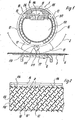
- Fig. 1 eine Auftragsvorrichtung innerhalb eines Siebzylinders einer Siebdruckmaschine im Querschnitt,
- Fig. 2 eine Seitenansicht eines Verdrängerkörpers gemäß dem Ausführungsbeispiel der Fig. 1 außerhalb des Gehäuses der Auftragsvorrichtung gesehen,
- Fig. 3 das Ausführungsbeispiel einer Schlitzrakel im Querschnitt mit erfindungsgemäß ausgestaltetem Zuflußkanal,
- Fig. 4 und 5 zwei weitere mögliche Ausführungsbeispiele der Ausbildung von Leitblechen in schematischer Seitenansicht,
- Fig. 6 ein weiteres Ausführungsbeispiel einer Auftragsvorrichtung im Querschnitt,
- Fig. 7 ein weiteres Ausführungsbeispiel einer Auftragsvorrichtung, ebenfalls im Querschnitt.
- 1 shows an application device within a screen cylinder of a screen printing machine in cross section,
- 2 is a side view of a displacer according to the embodiment of FIG. 1 seen outside the housing of the application device,
- 3 shows the exemplary embodiment of a slotted doctor blade in cross section with an inflow channel designed according to the invention,
- 4 and 5 two further possible embodiments of the formation of baffles in a schematic side view,
- 6 shows a further exemplary embodiment of an application device in cross section,
- Fig. 7 shows another embodiment of an application device, also in cross section.
Die in Fig. 1 gezeigte Auftragsvorrichtung 1 arbeitet wie eine Schlitzrakel. Als Schlitzrakel versteht man eine Auftragsvorrichtung, vorzugsweise mit einem allseitig geschlossenen Rakelgehäuse. Eine derartige Schlitzrakel ist nur zur Auftragsebene offen, und zwar im Rakelschlitz 111. Im Inneren dieses Gehäuses kann das verschäumte Medium unter atmosphärischem Druck oder einem höheren als atmoshärischem Druck stehen, was durch den spaltförmigen, gegen die Warenbahn bzw. die Schablone gerichteten Austrittsbereich auf die Ware gelangt. Dabei kann das gesamte Rakelgehäuse bzw. die gesamte Auftragsvorrichtung mit Zuführungsrohren od.dgl. für das Medium versehen sein.The
Der Begriff "Schlitzrakel" ist aber nicht einschränkend 'zu verstehen. Es besteht die Möglichkeit, Öffnungen anstelle eines Schlitzes einzusetzen.However, the term “slot doctor blade” is not to be understood as restrictive. It is possible to use openings instead of a slot.
Eine Auftragsvorrichtung 1 ist bei dem dargestellten Ausführungsbeispiel im Inneren eines Siebzylinders 2 angeordnet, der beliebig ausgebildet sein kann, beispielsweise nach der DE-PS 20 26 492. Die Auftragsvorrichtung besteht bei dem dargestellten Ausführungsbeispiel aus einem Rohr 10 mit Rakelfuß 11 und einem im Inneren desselben angeordneten Verdrängungskörper 12, wobei Rohr 10 und Verdrängungskörper 12 unterschiedliche Durchmesser haben, konzentrisch zueinander angeordnet sind und in einem Abstand zueinander liegen, wobei dieser Abstand gleichzeitig den Zuführungskanal 13 bildet. Der Verdrängungskörper 12 kann auch gleichzeitig Zuführungsrohr für das verschäumte Medium sein, wobei der Schaum beispielsweise erzeugt werden kann mit einem Schaumgenerator gemäß der DE-05 25 23 062.An
Bei dem dargestellten Ausführungsbeispiel ist das Innere des Verdrängungskörpers 12 gleichzeitig die Schaumzuführung. Im oberen Bereich wird der Verdrängungskörper 12 abgedeckt durch eine Abschlußplatte 14 mit Durchtrittsquerschnitten 114, die auf der gesamten Arbeitsbreite, vorzugsweise gleichmäßig verteilt angeordnet sind.In the illustrated embodiment, the interior of the
Oberhalb der Abschlußplatte 14 liegt im Abstand zu dieser eine Deckplatte 15, die eine nutartige Ausnehmung 115 aufweist, die sich ebenfalls über die Arbeitsbreite erstreckt. Der aus dem Innenraum 112 des Verdrängungskörpers 12 durch die Durchtrittsquerschnitte 114 ausströmende Schaum wird somit in diesem Bereich fraktioniert und gerät in die nutartige Ausnehmung 115 der Deckplatte 15 und wird bereits in diesem Bereich vereint. Durch die Zwischenräume oder Schlitze 214 wird der Schaum in die Zuflußkanäle 13 gezwängt. Diese Schlitze 214 sind relativ schmal und doch breit gehalten und dienen bereits zur Breitenverteilung des Schaumes. Die nutartige Ausnehmung 15 ist somit zunächst Stauraum und gleichzeitig Abgaberaum in den Schlitz oder die Schlitze 214 zur Breitenverteilung.Above the
Anschließend gelangt der Schaum jeweils rechts oder links in den Zuführungskanal 13.The foam then reaches the
Erfindungsgemäß liegen in diesen Zuführungskanälen 13 Ablenkkörper für den Schaum, bestehend aus mit Durchtrittsquerschnitten versehenen Leitwänden 16. Diese Leitwände 16 haben eine Höhe, die dem Durchflußquerschnitt entspricht und sind derart ausgebildet, daß ihre Standrichtung in unter schiedlichen, aufeinanderzugerichteten Winkeln zur Durchflußrichtung liegt. Gemäß den Ausführungsbeispielen der Fig. 1 und 2 bilden die Leitwände ein Gitterwerk, bestehend aus sich kreuzenden, jeweils auf Lücke gestellten Leitwandabschnitten 16 und 116. Die Lücken sind in Fig. 2 jeweils mit 16' und 116' bezeichnet. Die das Gitterwerk bildenden Leitwandabschnitte sind in Reihen angeordnet und in den Reihen liegen sie fluchtend zueinander, wobei sie ein Spiel mit nach links laufenden Abschnitten und ein Spiel mit nach rechts laufenden Abschnitten bilden. Dies ist deutlich in Fig. 2 ersichtlich. Der somit in Pfeilrichtung A einströmende Schaum, der bereits in den Schlitzen 214 verteilt wurde, staut sich zunächste in den oberen Kanalabschnitten, bevor er zu den Ablenkkörpern gelangt. Hier wird der Schaum abwechselnd nach rechts und links geleitet und die einzelnen Schaumströme werden durch das Aufeinanderzuführen miteinander vermengt, wieder geteilt, wieder aufeinander zugeführt usw., bis der Schaum den Bereich der Ablenkkörper und Leitwandabschnitte verläßt und in einen Stauraum 13' gelangt, der den Durchflußquerschnitten 110 des Rohres 10 vorgelagert ist. Unterhalb dieser Durchflußquerschnitte, die Bohrungen od.dgl. sein können ggf. auch ein Schlitz, liegt wiederum ein Aufnahmeraum 111 mit einem Verdrängungsstab 17, der sich ebenfalls axial über die gesamte Arbeitsbreite der Vorrichtung erstreckt. Er ist dem Auftragsschlitz 212 des Rakelfußes 11 vorgelagert.According to the invention, 13 baffles for the foam, consisting of
Der Schaum gelangt dann auf die in der angegebenen Pfeilrichtung laufende Ware 4, die auf einem Drucktuch 5 liegen kann oberhalb eines Gegendruckkörpers 6.The foam then arrives at the
In Fig. 3 ist ein Ausführungsbeispiel gezeigt einer einfachen Schlitzrakelausführung. Die Auftragsvorrichtung 1 besteht hier wiederum aus einem Rohr 10 mit Rakelfuß 11, der genauso ausgebildet sein kann wie bei dem Ausführungsbeispiel der Fig. 1. Gleiche Bezugszeichen deuten auf die gleichen Teile. Im Inneren dieser Auftragsvorrichtung wird der Zuführungskanal 13 durch zwei Wände 113 gebildet, die sich nach oben in einer gleichmäßig sich fortsetzenden nach außen gerichteten Rundung erstrecken. Zuführungsrohre 18 leiten den Schaum in die obere tulpenartige Öffnung 313 und weisen wiederum Durchtrittsquerschnitte 114 auf. Dieser obere Raum, der durch die tulpenartige Öffnung 313 entsteht, kann durch eine Membran 19 abgedeckt sein, wobei oberhalb dieser Membrane ein Druckpolster, und zwar ein regelbares Druckpolster, angeordnet sein kann. Dieses Druckpolster legt sich auf den zulaufenden Schaum, so daß dieser mit gleichmäßigem Druck durch den Zuführungskanal 13 geführt wird. Im Zuführungskanal 13 liegen wieder Ablenkkörper, und zwar wieder Leitwände, deren Standrichtung in unterschiedlichen, aufeinanderzugerichteten Winkeln zur Durchflußrichtung liegt. Diese Leitwände bilden wieder ein Gitterwerk, bestehend aus sich kreuzenden, jeweils auf Lücke gestellten Leitwandabschnitten. Diese können genauso ausgebildet sein, wie es in Fig. 2 für das Ausführungsbeispiel der Fig. 1 gezeigt ist oder wie sie andere Figuren zeigen.In Fig. 3 an embodiment of a simple slot doctor blade design is shown. The
In Fig. 4 ist ein Ausführungsbeispiel der Anordnung von Leit wandabschnitten 16, 116 gezeigt. Diese bilden ein Wabenmuster und stehen jeweils auf Lücke zueinander. Sie können rhombenartige Zwischenräume zwischen sich lassen.In Fig. 4 an embodiment of the arrangement of
In Fig. 5 ist ein Ausführungsbeispiel gezeigt, bei dem die beiden Spiele von Leitwänden, die sich nach rechts und links neigen, jeweils aus unterschiedlich langen Leitwänden bestehen, und zwar jeweils lange und kurze Leitwände im Wechsel zueinander angeordnet sind.In Fig. 5 an embodiment is shown in which the two games of baffles that tilt to the right and left each consist of baffles of different lengths, namely long and short baffles are alternately arranged.
Die Variationsmöglichkeit der Anordnung von Leitwänden ist vielfach. Sehr vorteilhaft ist aber die Ausführung gemäß Fig. 2. ' Immer sind die Kanäle aber vollständig bzw. fast vollständig ausgefüllt mit den Leitwänden 16. In Fig. 6 ist ein Ausführungsbeispiel gezeigt, bei dem das innere Rohr nicht als Verdrängungskörper ausgebildet ist, sondern eine beliebige Formgestaltung haben kann, wobei Verdrängungskörper 12 auf die Außenwände des Innenrohres 212 aufgesetzt sind. Das Innenrohr 212 hat Schaumzuführungsrohre 18, wobei das Innenrohr 212 im oberen Bereich ebenfalls abgedeckt ist durch eine Abschlußplatte 14 und einer im Abstand zu dieser angeordneten Deckplatte 15, wobei beide Platten wieder Schlitze 214 bilden. Das Innenrohr 212 bildet Auflageschultern 312, genauso wie der Verdrängungskörper 12 der Fig. 1.There are many possible variations in the arrangement of guide walls. However, the embodiment according to FIG. 2 is very advantageous. However, the channels are always completely or almost completely filled with the
Den Durchtrittsquerschnitten 114 zugeordnet ist jeweils eine Rohrmündung der Zuführungsrohre 18.A pipe mouth of the
Auf den Verdrängungskörpern 12 dieses Ausführungsbeispieles sind nun wiederum in den Kanälen 13 die Ablenkkörper oder Leitwände 16 aufgesetzt. Sie können aus dem Material herausgearbeitet sein. Die ganze Vorrichtung kann aber auch aus Blech bestehen und die Leitwände können aufgeschweißt oder aufgeklebt sein.The deflecting bodies or guide
Beim Ausführungsbeispiel der Fig. 7, das im wesentlichen dem der Fig. 1 gleicht, werden zur Bildung der Ablenkkörper Kunststoffmatten auf die Außenmantelfläche des Verdrängungskörpers 12 aufgesetzt. Diese Kunststoffmatten haben angespritzte oder aufgeklebte Leitwände 16 bzw. 116. Diese können mit der Matte 216 eine Einheit bilden.In the embodiment of FIG. 7, which is essentially the same as that of FIG. 1, plastic mats are placed on the outer surface of the
Somit ist die Möglichkeit gegeben, daß das Gitterwerk der Leitwandabschnitte aus in Reihen angeordneten Leitwandabschnitten bestehen und in Reihen fluchtend zueinanderliegenden Leitwandabschnitten, wobei sie ein Spiel nach rechts laufender Abschnitte und ein Spiel nach links laufender Abschnitte bilden. Diese Leitwandabschnitte können im Winkel von 30° bis 60° zur Durchflußrichtung angeordnet sein. Am vorteilhaftesten sind Leitwandabschnitte, die im Winkel von 45° zur Durchflußrichtung angeordnet sind. Dabei stehen dann die Leitwandabschnitte eines Spieles im rechten Winkel zu den Leitwandabschnitten des zweiten Spieles.Thus, there is the possibility that the latticework of the guide wall sections consist of guide wall sections arranged in rows and guide wall sections which are aligned with one another in rows, forming a play to the right-running sections and a play to the left-running sections. These guide wall sections can be arranged at an angle of 30 ° to 60 ° to the flow direction. The most advantageous are baffle sections which are arranged at an angle of 45 ° to the flow direction. The baffle sections of one game are then at right angles to the baffle sections of the second game.
Ferner besteht die Möglichkeit, daß die innerhalb eines Spieles nach einer Seite gerichteten Leitwandabschnitte größer ausgebildet sind als ihre Durchflußquerschnitte, wobei die parallellaufenden Leitwandabschnitte jeweils versetzt zueinanderliegen. Ferner besteht die Möglichkeit, daß jeweils zwei Leitwandabschnitte in ihrem Durchflußquerschnitt einen Leitwandabschnitt des im Winkel : zu ihnen stehenden Leitwandabschnittes des zweiten Spieles aufnehmen, der somit größer ausgebildet ist. Bei Fig. 5 wird jeweils ein Leitwandabschnitt sogar von drei querstehenden Leitwandabschnitten aufgenommen.There is also the possibility that the guide wall sections directed to one side within a game are larger than their flow cross-sections, the parallel guide wall sections each being offset from one another. Furthermore, there is the possibility that in each case two guide wall sections in their flow cross section accommodate a guide wall section of the guide wall section of the second game which is at an angle to them and which is thus made larger. In FIG. 5, one baffle section is even received by three transverse baffle sections.
Bei der Auftragsvorrichtung ist es wesentlich, daß der oder die Zuflußkanäle 13 in ihrem Durchflußquerschnitt vollständig oder fast vollständig von den Leitwänden 16 ausgefüllt sind und die Höhe der Leitwände 16 dem Durchflußquerschnitt entspricht.In the application device, it is essential that the flow channel or
Die einzelnen Leitwandabschnitte können verzahntzueinanderstehen, d.h. teilweise sich überlappend liegen. Es ist eine große Anzahl von Variationen denkbar und möglich. Diese Leitwandabschnitte können auch als aufgeschweißte Rippen, aufgeklebte Rippen, als Wabenteile, labyrinthartig u.dgl..ausgebildet sein, sie können aus Kunststoff, Aluminium, Blech bestehen. Die Leitwandabschnitte können aufgeschweißt, aufgeklebt, angeformt, angesetzt, angegossen werden. Wichtig ist bei einer labyrinthartigen Ausbildung, daß die verschiedenen, sich durch das Labyrinth bildenden Ströme immer wieder aufeinanderzugeführt werden, so daß hier ein Stau entsteht, sich eine Verteilung wieder ergibt und wieder aufeinanderzugeführt werden in gleichmäßigen, ggf. auch ungleichmäßigen Rhythmen. Der Schaum soll somit durchmengt werden, die Grenzschichten zwischen den einzelnen Schaumsträngen sollen immer wieder aufgelöst werden und sich neu bildende Grenzschichten wieder zerstört werden.The individual guide wall sections can be interlocked, i.e. partially overlapping. A large number of variations are conceivable and possible. These guide wall sections can also be designed as welded-on ribs, glued-on ribs, as honeycomb parts, like a labyrinth, and the like. They can consist of plastic, aluminum, sheet metal. The guide wall sections can be welded, glued, molded, attached, cast on. It is important in a labyrinthine design that the various currents formed by the labyrinth are brought together again and again so that there is a traffic jam, there is a distribution again and are brought together again in uniform, possibly also non-uniform rhythms. The foam should thus be mixed, the boundary layers between the individual foam strands should be dissolved again and again, and newly forming boundary layers should be destroyed again.
Die Vorrichtung dient im wesentlichen zum Färben bzw. Bedrucken oder auch zum Bemustern von Ware, beispielsweise auch durch Auftragen von Schaum, der lediglich aus Wasser und Tensiden besteht, um beispielsweise in einer nassen, bedruckten, ggf. unigefärbten Ware Farbverdrängungen oder Entfärbungen vorzunehmen. Mit dem Schaum kann die Warenbahn behandelt werden, beschichtet od.dgl. Im wesentlichen ist an eine Arbeitsweise gedacht ähnlich eines Siebdruckes, gleichgültig nun, ob das Sieb oder die Schablone als Siebzylinder, als Siebband, als ebene Schablone od.dgl. ausgebildet ist. Als Substrat kommen insbesondere Warenbahnen mit faseriger Struktur in Betracht, wie Textilien aller Art, darunter auch Teppiche, Florware, Samte, ferner Vliese, aber auch Filze. Auch Non-woven oder Papier kann mit der Auftragsvorrichtung bedruckt, gefärbt, behandelt werden, ggf. auch beschichtet.The device is essentially used for dyeing or printing or also for patterning goods, for example also by applying foam which consists only of water and surfactants, for example in order to carry out color displacements or discoloration in a wet, printed, possibly uncoloured goods. The material can be treated, coated or the like with the foam. Essentially it is thought of a method of working similar to screen printing, irrespective of whether the screen or the template is used as a screen cylinder, as a screen belt, as a flat template or the like. is trained. In particular, webs with a fibrous structure are considered as substrates, such as textiles of all kinds, including carpets, pile goods, velvet, also nonwovens, but also felts. Non-woven or paper can also be printed, dyed, treated, or even coated with the application device.
Der Auftrag auf feste Waren, wie z.B. Glas, Kunststoff oder Keramik, ist möglich.The order for solid goods, such as Glass, plastic or ceramic is possible.
Die offenbarten Merkmale, einzeln und in Kombination, werden, soweit sie gegenüber dem Stand der Technik neu sind, als erfindungswesentlich angesehen.The disclosed features, individually and in combination, are regarded as essential to the invention insofar as they are new compared to the prior art.
Claims (10)
Applications Claiming Priority (2)
| Application Number | Priority Date | Filing Date | Title |
|---|---|---|---|
| DE3310732 | 1983-03-24 | ||
| DE19833310732 DE3310732A1 (en) | 1983-03-24 | 1983-03-24 | APPLICATION DEVICE FOR APPLYING A FOAMED MEDIUM |
Publications (1)
| Publication Number | Publication Date |
|---|---|
| EP0120472A1 true EP0120472A1 (en) | 1984-10-03 |
Family
ID=6194535
Family Applications (1)
| Application Number | Title | Priority Date | Filing Date |
|---|---|---|---|
| EP84103172A Withdrawn EP0120472A1 (en) | 1983-03-24 | 1984-03-22 | Device for applying a foamed material |
Country Status (2)
| Country | Link |
|---|---|
| EP (1) | EP0120472A1 (en) |
| DE (1) | DE3310732A1 (en) |
Cited By (7)
| Publication number | Priority date | Publication date | Assignee | Title |
|---|---|---|---|---|
| US5063646A (en) * | 1990-07-27 | 1991-11-12 | Gaston County Dyeing Machine Co. | Means and method for extracting moisture from a traveling web of textile material |
| US6503412B1 (en) | 2000-08-24 | 2003-01-07 | Kimberly-Clark Worldwide, Inc. | Softening composition |
| US6761800B2 (en) | 2002-10-28 | 2004-07-13 | Kimberly-Clark Worldwide, Inc. | Process for applying a liquid additive to both sides of a tissue web |
| US6797116B2 (en) | 2002-05-31 | 2004-09-28 | Kimberly-Clark Worldwide, Inc. | Method of applying a foam composition to a tissue product |
| US6797319B2 (en) | 2002-05-31 | 2004-09-28 | Kimberly-Clark Worldwide, Inc. | Application of foam to tissue products using a liquid permeable partition |
| US6805965B2 (en) | 2001-12-21 | 2004-10-19 | Kimberly-Clark Worldwide, Inc. | Method for the application of hydrophobic chemicals to tissue webs |
| US6835418B2 (en) | 2002-05-31 | 2004-12-28 | Kimberly-Clark Worldwide, Inc. | Use of gaseous streams to aid in application of foam to tissue products |
Citations (2)
| Publication number | Priority date | Publication date | Assignee | Title |
|---|---|---|---|---|
| US3610201A (en) * | 1969-04-21 | 1971-10-05 | Anetsberger Bros Inc | Viscous material spreader |
| EP0047908A1 (en) * | 1980-09-16 | 1982-03-24 | Mathias Mitter | Coating apparatus for sheet-like material |
Family Cites Families (3)
| Publication number | Priority date | Publication date | Assignee | Title |
|---|---|---|---|---|
| DE2026492C3 (en) * | 1970-05-30 | 1975-07-17 | Mitter & Co, 4815 Schloss Holte | Arrangement for storing the print heads attached to the ends of a stencil cylinder in printing machines for webs of material |
| DE2523062C3 (en) * | 1975-05-24 | 1980-02-28 | Hoechst Ag, 6000 Frankfurt | Device for the continuous application of a liquid treatment liquor in the form of foam to wide-spread textile material |
| US4297860A (en) * | 1980-07-23 | 1981-11-03 | West Point Pepperell, Inc. | Device for applying foam to textiles |
-
1983
- 1983-03-24 DE DE19833310732 patent/DE3310732A1/en not_active Withdrawn
-
1984
- 1984-03-22 EP EP84103172A patent/EP0120472A1/en not_active Withdrawn
Patent Citations (2)
| Publication number | Priority date | Publication date | Assignee | Title |
|---|---|---|---|---|
| US3610201A (en) * | 1969-04-21 | 1971-10-05 | Anetsberger Bros Inc | Viscous material spreader |
| EP0047908A1 (en) * | 1980-09-16 | 1982-03-24 | Mathias Mitter | Coating apparatus for sheet-like material |
Cited By (7)
| Publication number | Priority date | Publication date | Assignee | Title |
|---|---|---|---|---|
| US5063646A (en) * | 1990-07-27 | 1991-11-12 | Gaston County Dyeing Machine Co. | Means and method for extracting moisture from a traveling web of textile material |
| US6503412B1 (en) | 2000-08-24 | 2003-01-07 | Kimberly-Clark Worldwide, Inc. | Softening composition |
| US6805965B2 (en) | 2001-12-21 | 2004-10-19 | Kimberly-Clark Worldwide, Inc. | Method for the application of hydrophobic chemicals to tissue webs |
| US6797116B2 (en) | 2002-05-31 | 2004-09-28 | Kimberly-Clark Worldwide, Inc. | Method of applying a foam composition to a tissue product |
| US6797319B2 (en) | 2002-05-31 | 2004-09-28 | Kimberly-Clark Worldwide, Inc. | Application of foam to tissue products using a liquid permeable partition |
| US6835418B2 (en) | 2002-05-31 | 2004-12-28 | Kimberly-Clark Worldwide, Inc. | Use of gaseous streams to aid in application of foam to tissue products |
| US6761800B2 (en) | 2002-10-28 | 2004-07-13 | Kimberly-Clark Worldwide, Inc. | Process for applying a liquid additive to both sides of a tissue web |
Also Published As
| Publication number | Publication date |
|---|---|
| DE3310732A1 (en) | 1984-11-22 |
Similar Documents
| Publication | Publication Date | Title |
|---|---|---|
| EP0472050B1 (en) | Apparatus for applying a liquid-film to a material web | |
| DE3238084A1 (en) | DEVICE FOR EVENLY DELIVERING, DISTRIBUTING AND APPLYING A FOAMED FLEET OF APPLICATION TO A PREFERRED TEXTILE TRACK OR THE LIKE. | |
| EP0047908A1 (en) | Coating apparatus for sheet-like material | |
| DE2300289A1 (en) | DEVICE FOR APPLYING LIQUID OR PASTOESE MEDIA, IN PARTICULAR FOR SCREEN PRINTING MACHINES | |
| DE2935413A1 (en) | METHOD AND DEVICE FOR CONTINUOUSLY TREATING TEXTILES AND THE LIKE. RAILWAYS | |
| EP0047907B1 (en) | Coating apparatus for sheet-like materials | |
| EP0120472A1 (en) | Device for applying a foamed material | |
| DE4228610B4 (en) | Paper guide for web-fed rotary printing machines | |
| DE3146828C2 (en) | Device for the continuous application of a very small amount of liquid to a web of material | |
| EP0047887A1 (en) | Device for applying a medium (finishing bath) to a surface by means of an application device | |
| DE2728501A1 (en) | DEVICE FOR THE PRODUCTION OF PRINTING INKS FOR FABRIC PRINTING MACHINES | |
| EP0098362A1 (en) | Slot for applying foamed coating materials onto sheet-like materials | |
| DE2332153C3 (en) | Device for sucking in the color printed by a continuously operating rotary printing machine onto a horizontally guided, preferably textile material web | |
| DE3200171C2 (en) | Device for applying an application medium, preferably provided with a dye, to flat goods | |
| EP0049362A1 (en) | Feeding device for a coating medium on a surface, whereby the coating medium is placed in front of a coating device | |
| EP0069982A1 (en) | Apparatus for coating sheet like materials with liquids, foams or pastes | |
| AT391108B (en) | DEVICE ON STENCIL PRINTING MACHINES, IN PARTICULAR ROTARY STENCIL PRINTING MACHINES | |
| DE3034803A1 (en) | Strip material screen-printing process - deposits foam material containing dye on screen and presses it through to make printed pattern | |
| DE611585C (en) | Headbox on Fourdrinier paper machines | |
| EP0108274A1 (en) | Apparatus for supplying a foam and for coating a textile web by it | |
| DE3218095A1 (en) | Applicator device for applying liquid, pasty or foamed media onto sheet-like products | |
| EP0123019A1 (en) | Coating device formed by a doctor with a slit or the like | |
| DE3226651C2 (en) | Device for applying foamed liquor to flat, fibrous structure exhibiting goods, such as textiles, especially webs of goods | |
| DE2942691A1 (en) | RIDER DEVICE FOR FASTENING ON A ROLLER OR CYLINDER OF AN INK | |
| EP0100885A1 (en) | Apparatus for coating webs with foams |
Legal Events
| Date | Code | Title | Description |
|---|---|---|---|
| PUAI | Public reference made under article 153(3) epc to a published international application that has entered the european phase |
Free format text: ORIGINAL CODE: 0009012 |
|
| AK | Designated contracting states |
Designated state(s): AT CH DE FR GB IT LI NL |
|
| RAP1 | Party data changed (applicant data changed or rights of an application transferred) |
Owner name: MITTER, MATTHIAS ERICH, JR. Owner name: MITTER, MATHIAS |
|
| RIN1 | Information on inventor provided before grant (corrected) |
Inventor name: MITTER, MATHIAS |
|
| 17P | Request for examination filed |
Effective date: 19850329 |
|
| STAA | Information on the status of an ep patent application or granted ep patent |
Free format text: STATUS: THE APPLICATION HAS BEEN WITHDRAWN |
|
| RAP1 | Party data changed (applicant data changed or rights of an application transferred) |
Owner name: RAMISCH KLEINEWEFERS GMBH |
|
| 18W | Application withdrawn |
Withdrawal date: 19870220 |
|
| RIN1 | Information on inventor provided before grant (corrected) |
Inventor name: MITTER, MATHIAS |