EP0120080B1 - Method and system for identifying documents - Google Patents
Method and system for identifying documents Download PDFInfo
- Publication number
- EP0120080B1 EP0120080B1 EP83903343A EP83903343A EP0120080B1 EP 0120080 B1 EP0120080 B1 EP 0120080B1 EP 83903343 A EP83903343 A EP 83903343A EP 83903343 A EP83903343 A EP 83903343A EP 0120080 B1 EP0120080 B1 EP 0120080B1
- Authority
- EP
- European Patent Office
- Prior art keywords
- waveforms
- location
- peak
- document
- identifiable features
- Prior art date
- Legal status (The legal status is an assumption and is not a legal conclusion. Google has not performed a legal analysis and makes no representation as to the accuracy of the status listed.)
- Expired
Links
Images


Classifications
-
- G—PHYSICS
- G07—CHECKING-DEVICES
- G07F—COIN-FREED OR LIKE APPARATUS
- G07F7/00—Mechanisms actuated by objects other than coins to free or to actuate vending, hiring, coin or paper currency dispensing or refunding apparatus
- G07F7/08—Mechanisms actuated by objects other than coins to free or to actuate vending, hiring, coin or paper currency dispensing or refunding apparatus by coded identity card or credit card or other personal identification means
-
- G—PHYSICS
- G06—COMPUTING; CALCULATING OR COUNTING
- G06V—IMAGE OR VIDEO RECOGNITION OR UNDERSTANDING
- G06V10/00—Arrangements for image or video recognition or understanding
- G06V10/98—Detection or correction of errors, e.g. by rescanning the pattern or by human intervention; Evaluation of the quality of the acquired patterns
-
- G—PHYSICS
- G06—COMPUTING; CALCULATING OR COUNTING
- G06V—IMAGE OR VIDEO RECOGNITION OR UNDERSTANDING
- G06V30/00—Character recognition; Recognising digital ink; Document-oriented image-based pattern recognition
- G06V30/10—Character recognition
- G06V30/22—Character recognition characterised by the type of writing
- G06V30/224—Character recognition characterised by the type of writing of printed characters having additional code marks or containing code marks
- G06V30/2253—Recognition of characters printed with magnetic ink
-
- G—PHYSICS
- G07—CHECKING-DEVICES
- G07F—COIN-FREED OR LIKE APPARATUS
- G07F7/00—Mechanisms actuated by objects other than coins to free or to actuate vending, hiring, coin or paper currency dispensing or refunding apparatus
- G07F7/08—Mechanisms actuated by objects other than coins to free or to actuate vending, hiring, coin or paper currency dispensing or refunding apparatus by coded identity card or credit card or other personal identification means
- G07F7/0806—Details of the card
- G07F7/0833—Card having specific functional components
Definitions
- This invention relates generally to waveform matching for identification purposes, and more specifically it relates to waveform matching as it is used to identify documents.
- MICR line Magnetic Ink Character Recognition
- the record media such as bank checks and deposit slips, for example, are processed in an Entry or a First Pass Unit (FPU) where certain operations are performed.
- the record media are generally processed in groups or "batches" of about 250-300 checks per batch, for example.
- the MICR data is read from the checks for a batch of checks and the data read may be stored in a memory unit.
- the monetary amount of each check in the batch of checks is read or obtained by mechanical (character recognition) or manual methods, and the monetary amount is stored in a memory unit.
- the monetary amount for each check is then encoded or printed on the corresponding check and some physical sorting of the batch of checks may be done after the encoding is completed.
- the encoding and sorting is done, for example, at a second unit, referred to hereinafter as a Second Pass Unit (SPU).
- SPU Second Pass Unit
- the MICR data is read again to provide a second reading which is compared with the first reading obtained from the FPU to make sure that the checks are properly identified and have remained in the same order.
- the monetary amount for that check is then encoded thereon, in the example described. Thereafter, the checks may be sorted by the SPU by various criteria as is conventionally done.
- One type of comparison or verification method performed with MICR data is to compare the second reading of each character of a MICR line of data with each corresponding character obtained from the first reading, as in the example described above; however, known comparison or verification methods of this type improperly or falsely reject correct readings in about 1% of the comparisons.
- Another method for comparing entails matching the entire waveform received from the first MICR reading at the FPU with the entire waveform received from the second MICR reading at the SPU. Because the check transport mechanisms in the FPU and the SPU move the checks at different actual speeds, even though the transports are designed to operate at the same speed, the correlation between first and second readings becomes progressively unsynchronized near the end-of- the-reading scans.
- waveform analysis and comparison techniques such as threshold determination, peak selection and window searching.
- a method of identifying documents having document identifying characters recorded thereon including the steps (a) of sensing said characters on a said document to generate a set of first waveforms each corresponding to a sensed character and having identifiable features, and (b) sensing said characters on a said document in a sensing operation subsequent in time to said step (a) to generate a set of second waveforms each corresponding to a sensed character and having identifiable features, characterized by the steps of (c) obtaining from said first waveforms significant identifiable features each having a value and a location with respect to a starting point of the associated waveform, said significant identifiable features being obtained from selected ones of said first waveforms, the selected waveforms having greater recognition distances in respect of matching templates, said distances being representative of the degree of disconformity between the waveforms and the matching templates, than the non-selected waveforms; (d) utilizing said value and location of each said significant identifiable feature obtained in said step (c) to determine the location for an anticipated corresponding
- an apparatus for identifying documents having document identifying features recorded thereon including first reading means for sensing said characters on a said document to generate a set of first waveforms each corresponding to a sensed character and having identifiable features, and second reading means for sensing said characters on a said document in a sensing operation subsequent in time to the sensing operation used to generate said set of first waveforms, said second reading means being arranged to generate a set of second waveforms each corresponding to a sensed character and having identifiable features, characterized by data acquisition means for obtaining from said first waveforms significant identifiable features each having a value and a location with respect to a starting point of the associated waveform, said significant identifiable features being obtained from selected ones of said first waveforms, the selected waveforms having greater recognition distances in respect of matching templates, said distances being representative of the degree of disconformity between the waveforms and the matching templates, than the non-selected waveforms, determining means for utilizing said value and location of each said significant identifiable feature obtained by
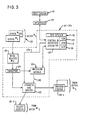
- Fig. 1 shows a portion of a general banking system 10 in which this invention may be used.
- the system 10 includes a First Pass Unit (FPU) 12, shown in dashed outline.
- the FPU 12 includes a MICR reader #1 which is designated as 14, a Data Acquisition Module 16, (referred to hereinafter as DAM 16), and a transport mechanism simply referred to as transport 18.
- the Reader #1 in the FPU 12 performs the function of reading the MICR line of data on each record medium or banking check in the embodiment described.
- the DAM 16 performs the function of acquiring data (as will be described hereinafter) from the record media, and the transport 18 performs the function of receiving a batch of checks like 20 and moving them serially, in reading relationship with the reader 14 and thereafter moving them out of the FPU 12.
- the MICR line of data which is read by the reader 14 (Fig. 1) and the data which is acquired by the DAM 16 for each check of the batch 20 of checks may be forwarded via a conventional interface 22 to a conventional host system designated generally as 24.
- the host system 24 includes an entry means 26, a display 28 for communicating with a user of the system 24, a Read Only Memory (ROM) 30 for storing instructions and programs, a processor (MP) 32 for performing operations, a Random Access Memory (RAM) 34, and control and interface circuitry 36.
- ROM Read Only Memory
- MP processor
- RAM Random Access Memory
- the Data Acquisition Module (DAM 16) is shown in more detail in Fig. 4. Basically, the DAM 16 receives data from the reader 14 and treats it in a special way (to be described hereinafter) and then forwards the derived data to the host system 24 via the interface 22.
- the reader 14 (Fig. 1) provides the DAM 16 with data on four different lines as shown.
- the reader 14 is conventional and it includes, for example, logic circuitry 38 and an analog to digital (A/D) unit 40.
- the logic circuitry 38 also includes conventional circuits to interpret the MICR waveforms as the checks 20 are moved in reading relationship with a read head 42.
- the MICR data is printed in a specific pattern such as an E13B font so that the MICR data or characters generate specific waveforms when they are read at a subsequent reading operation.
- the specific waveforms are digitized and compared conventionally with "templates" to produce numerical values or what are referred to as "recognition distances", which in effect, are used to identify the characters being read.
- recognition distances are routed from the logic circuitry 38 of reader 14 to the DAM 16 over a line 44.
- the logic circuitry 38 produces a "document present” signal on line 46.
- the logic circuitry 38 produces a "character start” signal on line 48.
- the A/D unit 40 produces a "digitized image" of each character read on the line 50.
- the sampling rate of the read head 42 and the velocity with which the transport 18 moves each check past the read head 42 are such as to produce 128 samples for each character on a MICR line on the check. Naturally, the number of samples and sampling rate may be modified to suit particular applications. In the embodiment described, there are up to about 30 characters on a MICR line on each check.
- each of the 128 samples of digitized output from the AID unit 40 for each character is comprised of an eight bit byte, with the first bit of the byte denoting a positive or negative value, and the remaining seven bits denoting the sampled amplitude.
- a positive value is designated by a binary 0 and a negative value is designated by a binary 1.
- the various outputs from the reader 14 are forwarded to the DAM 16 over lines 44, 46, 48, and 50 as mentioned, with the DAM 16 being shown in more detail in Fig. 4.
- the DAM 16 (Fig. 4) includes a conventional threshold circuit 52, a peak detector circuit 54, a First In, First Out memory unit hereinafter called FIFO 56 and a Data Acquisition System designated generally as 58 and hereinafter called DAS 58.
- the threshold circuit 52 (Fig. 4) includes conventional logic 60, a comparator 62 and an output 64.
- the comparator 62 is designed to produce an output other than zero at output 64 only when the amplitude of the digitized value in the byte of data coming from the A/D unit 40 is above 4 for positive values of the digitized data and is above 3 for negative values of the digitized data. Digitized amplitude values of the hypothetical waveform result in zero when they are less than the positive and negative threshold values mentioned. Normally, the same threshold values for positive and negative digitized amplitude values would be used; however, the different values used in this embodiment are used to overcome certain sensitivity deficiencies in the particular read head 42 used.
- 128 digitized samples are outputted from the threshold circuit 52 (for each character on the MICR line being read by the read head 42) over line 66 to the peak detector circuit 54.
- the peak detector circuit 54 includes logic circuitry 68 which receives the output from the threshold circuit 52 and also includes a first counter 70, a second counter 72, a subtractor circuit 74, a buffer 76, and an output 78. The operation of the peak detector circuit 54 will be described hereinafter.
- the DAM 16 also includes the DAS 58 shown in Fig. 4.
- the DAS 58 includes control and interface circuitry 80, a ROM 82 for providing control and sequencing, a RAM 84 for providing temporary storage during processing, and a processor referred to as MP 86.
- the DAM 16 receives a digitized waveform from an associated analog waveform (similar to hypothetical analog waveform 86 shown in Fig. 5) for each of the 30 characters on a MICR line on each of the checks in a batch like 20 in the embodiment described.
- the DAM 16 selects 12 digitized waveforms (out of the 30 characters on a check) to be forwarded to the RAM 34 of the host system 24.
- the 12 digitized waveforms selected are those which have the greatest "recognition distances". In essence, a recognition distance close to zero means that a particular character read conforms to the matching "template" for that character. A large recognition distance means that the character read does not conform to one of the character templates anticipated on the MICR line.
- a large recognition distance may be due to a "blemish” in the printing of that character, for example; however, this "blemish" is unique and can help to identify the particular check at a second or subsequent reading of that check. That is why those characters with the largest recognition distances are saved and used to identify the associated check in subsequent passes or readings.
- Each one of the checks in a batch 20 of checks has an identification number such as a MICR number like 88 (Fig. 2) which identifies the particular check, and it also has the associated MICR waveform signature 90 forming part of a data string 92 which is stored in the RAM 34 of the host system 24 for each of the checks in a batch 20.
- the waveform signature 90 includes the 12 digitized waveforms (treated as hereinafter described) corresponding to the 12 characters out of 30 which are selected to identify the particular check when that check and batch 20 of checks are processed later in another terminal or unit such as the Second Pass Unit 94 (SPU) shown in Fig. 3, and as described, generally, earlier herein.
- SPU Second Pass Unit
- step 98 of the flow chart 96 the DAM 16 looks for a document present signal as, for example, on line 46 in Fig. 4 to ascertain whether or not a document or check is present at the reader 14.
- a document present signal activates the DAM 16.
- step 102 lookfor a character start signal (on line 48). If there is no character start signal, the DAM 16 returns to step 100 via the loop shown, and progresses to step 102 where the DAM 16 again looks for a character start signal.
- the DAM 16 starts to utilize the output from the threshold circuit 52 as shown at step 104.
- the step 106 "open windows" is performed.
- the step 106 refers to the process of providing "parameters" or "end points" between which a search is made for a peak or peaks which may be included therebetween.
- a window #6 starts at sample #72, the point at which the amplitude of the digitized waveform 86 rises above the positive fixed threshold level, and ends at sample #86 at which the amplitude of the waveform 86 drops below the threshold level.
- windows exist for negative values of the waveform #86 (Fig. 5) as shown by the window #2 which starts at sample #20 and ends at sample #40, with a peak 2-1 occurring in window #2.
- window #2 which starts at sample #20 and ends at sample #40, with a peak 2-1 occurring in window #2.
- the counter 70 in Fig. 4 is used to provide a running count of the samples and is reset to zero with each new character start signal.
- the counter 72 in Fig. 4 is used to count the number of samples which occur within a window, and as previously described, each digitized sample is recorded as an eight bit byte.
- the subtractor 74 in the peak detector 54 (Fig. 4) is used to search for a peak located therein.
- This peak search (shown as step 108 in Fig. 6) is performed by examining sequential samples as they are received in a window. For example, if the i th sample is larger than the previous sample (i-1), the slope is considered positive; if the j th sample is smaller or less than the previous sample (i-1), the slope is considered negative.
- a slope of zero occurs when two consecutive, or sequential samples have the same value; this would be represented by a flat horizontal line in the waveform 86 shown in Fig. 5.
- a signal is created which causes the peak detector 54 to save the peak value and its sample location (from counter 70) in the buffer 76. It is possible that two peaks may exist within a window as shown by peaks 6-1 and 6-2 (Fig. 5) which exist in the window bounded by samples #72 and #86. Peaks also exist in the negative half of the waveform 86. For example, the highest negative peak in the window #2, which extends from sample #20 to sample #40, is peak 2-1.
- the hypothetical waveform 86 shown in Fig. 5 relates to MICR characters as previously explained; consequently, because a MICR character always produces initially a positive-going pulse when read and ends with a negative-going peak, the first window always starts at sample #0, and the associated waveform has a positive value at that point.
- Another situation is that if the first opening or first window is greater or wider than 16 samples, the window is divided in half. The first window ends at sample #18 in Fig 5 in the example portrayed.
- the first window is generally narrower than other windows because the character start circuitry (not shown) in the reader 14 will not indicate a "character start" signal 48 until the read head 42 (Fig. 1) is part way through the first peak of that waveform being read.
- the first window (from sample #0-#18) is divided into two windows marked 1A and 1 B as shown in Fig. 5, with the first window 1A extending from sample #0 to sample #9 and the second window 1 B extending from sample #9 to sample #18.
- a window width larger than 20 samples is divided into two windows as shown by the windows 7A and 7B in Fig. 5. Prior to dividing, the associated larger window extended from sample #88 to sample #116. Because there is no slope reversal or peak in window 7A, this window data may be discarded; the peak 7-1 in window 7B is saved.
- FIG. 4 Another situation handled by the peak detector 54 (Fig. 4) is that of a "flat peak” as shown by window #5 in Fig. 5. As soon as window #5 is opened, the amplitude values from the reader 14 remain substantially constant so as to produce no change in slope for most of the width of the window. Finally, the subtractor 74 ascertains that there is a negative slope at sample #62 as the peak amplitude falls below the threshold value to close window #5. The logic 68, associated with the peak detector 54, will then position the "peak” at the center of the window #5 after ascertaining the number of samples in the window (from the count in counter 72). The sample number at the center of window #5 along with the "peak” value are then stored in the buffer 76.
- the next step associated with the peak detector 54 is to select the peak or peaks to be saved for that character as shown by the peak select step 110 in Fig. 6.
- the peak detector 54 selects a maximum of 3 peaks and a minimum of 1 peak in each of the positive and negative halves of the associated waveform like 86 in Fig. 5.
- the logic 68 of the peak detector 54 will examine the sample number (i.e. location) of each of the stored peaks and will discard that peak which is within 10 samples of a nearby peak and also is the smaller of the two peaks.
- the logic 68 withdraws the peaks from the buffer 76 and arranges them in descending order of peak amplitude to begin the selection of peaks associated with step 110. Thereafter, the logic 68 performs certain operations on the ranked peaks. If the largest peak (for positive values) has a value which is four times greater than the second largest peak, then only the largest peak is saved and the remaining peaks are discarded.
- the second and smaller peaks are probably only noise peaks in this situation. If the second peak is larger than one fourth of the size of the largest peak, then the second peak is saved. If a third peak exists, in order to be saved it must be larger than the sum of the first and second largest peaks divided by five, otherwise it is discarded. It should be noted that because there are both positive and negative halves, there will be a maximum of 6 peaks and a minimum of 2 peaks saved for each character being read in the example described.
- the peaks or peak values are selected as represented by the peak select step 110 in Fig. 6, they are outputted from the output 78 (Fig. 4) and are stored in the FIFO 56 as represented by the step 112.
- the FIFO 56 is a memory device which is arranged to sequentially store the peak values saved along with their sample locations for each character being read. From step 112 in Fig. 6, the routine returns to step 100 to repeat the process described for a new or the next character.
- the recognition distance for each character scanned at the reader 14 is calculated therein and forwarded over line 44 to the DAS 58 (Fig. 4) where it is stored in the RAM 84 therein.
- the routine proceeds to step 114 at which the 12 "characters" or data sets out of 30 characters (in the embodiment described) are selected to identify the associated document.
- the 12 characters selected are those which have the greatest recognition distances as previously explained; these are the ones that are most expressive of uniqueness of the associated document.
- a conventional software routine stored in the ROM 82 (Fig.
- step 116 in Fig. 6 the routine shown therein returns to step 102 to repeat the process desscribed for the first character to be read on the new document.
- the data stored in the RAM 34 for each of the 12 characters selected for each document includes the peak values and their associated sample numbers; this data, referred to as the MICR waveform signature 90 (Fig. 2), is included for each of the documents in a batch (like 20) of documents along with the MICR #88 for that document.
- the MICR #88 is developed conventionally from the recognition distances.
- a reader as was done in Fig. 1.
- a reader like 120 in Fig. 3 may be part of the second pass unit (SPU) 94 as previously explained.
- SPU second pass unit
- Each of the checks is moved in reading relationship with MICR reader 120 by a conventional transport 124 which subsequently also moves each of the checks in printing relationship with the encoder and sorter 122.
- Those checks which are properly identified are encoded and exited from the SPU 94 via the encoder and sorter 122 to form an encoded batch 20-1 of checks.
- Those checks which are not properly identified, for example, are exited from the encoder and sorter 122 to form a reject batch 20-2 of checks.
- the waveform matching at the SPU 94 (Fig. 3) is effected in conjunction with a matching module 126.
- the function of the matching module 126 is to receive the first pass data retained in the host system 24 from the FPU 12 (which data is referred to as reference data) and compare the reference data with the second pass data developed in the SPU 94 (which data is referred to as test data).
- the matching module 126 indicates a "match" to the encoder and sorter 122 to enable the encoder to print data on the particular check just read at the reader 120 in the embodiment described. If no match between reference and test data occurs, the particular check just read is rejected by the encoder and sorter 122 to batch 20-2 as previously described.
- the SPU 94 (Fig. 3) is coupled to the host system 24 via a conventional interface 128, and the SPU 94 also includes a conventional SPU processing system 130, which includes control and interface circuitry 132, a ROM 134 for storing the associated programs, a RAM 136, and a processor (MP) 138. Suitable lines (not shown) extend from the control and interface circuitry 132 to the MICR reader 120, transport 124, and encoder and sorter 122 to provide conventional control where necessary or desirable.
- the matching module 126 (Fig. 3) is shown in more detail in Fig. 7, and it includes a peak detector 140 which is identical to the peak detector 54 (Fig. 4) already described.
- the peak detector 140 includes logic 142, counters 144 and 146, a subtractor 148, a buffer 150 and an output 152 which all function in the same manner as do the corresponding elements already described with regard to peak detector 54.
- the matching module 126 also includes a module control designated generally as 154 and which includes a RAM 156, a ROM 158 (for storing instructions), a processor (MP) 160, and control and interface circuitry 162.
- a module control designated generally as 154 and which includes a RAM 156, a ROM 158 (for storing instructions), a processor (MP) 160, and control and interface circuitry 162.
- a header card (not shown) but associated with the batch 20 of checks may be used to access the appropriate data strings 92 (Fig. 2) from the host system 24.
- the SPU system 130 downloads the data strings 92 to the module control 154 where they are momentarily stored in the RAM 156; this is the reference data as previously described, and it is transferred just prior to what is expected to be data from the same document derived from the read head 162 of the reader 120.
- the logic circuitry 164 of the reader 120 produces a document present signal on line 166, and also may produce the associated recognition distance on line 168, which lines 166 and 168 are coupled to the module control 154 for use thereby.
- a character start signal developed by the logic circuitry 164 is utilized by the peak detector 140 as previously explained with regard to peak detector 54.
- An A/D converter 170 converts the analog waveform read from the MICR line at the read head 162 to a digitized output which is forwarded to the logic 142 of the peak detector 140. The output of the A/D 170 is not thresholded prior to entering the associated peak detector 140 as was done in the FPU 12.
- the peak detector 140 produces peaks or the "test data" for each character on the associated MICR line of data on a check being read in the same manner with regard to peak determination as was done with the peak detector 54 in the FPU 16.
- the test data or peaks for each of the characters are forwarded from the peak detector 140 to the FIFO memory 172.
- This test data or peak data includes its discrete value as previously described and its associated sample number which is intrinsically located or positioned in the FIFO memory 172 whose output is fed into the module control 154.
- the peaks associated with only 12 characters out of a total of 30 characters for a check are used as reference data (in the example described) to identify the check in the waveform matching technique disclosed herein. If, for example, the first character selected as reference data were the 4th out of 30 characters, the associated reference data would be located in the RAM 156 of the module control 154 (Fig. 7). The test data or peaks coming from the FIFO memory 172 for the first three characters are disregarded by the module control 154, and the direct waveform matching begins when the test data for the fourth character arrives at the module control 154.
- the reference data or peaks for the 4th character are used to open up search windows with regard to the incoming test data or peaks from the FIFO memory 172 (Fig. 7).
- a reference peak occurs at sample #14 (out of 128 samples)
- the window boundary locations are given by the following equation: wherein:
- reference sample #120 for example, has a wider window than reference sample #20.
- the peak detector 140 calculates or determines the peaks in the same general manner as does peak detector 54 (Fig. 4) already described. Assuming that the checks in a batch of checks are in the proper order, the test peaks obtained from the SPU 94 should match the reference peaks obtained from the FPU 12.
- the waveform matching of this invention also includes some additional steps or operations which evaluate the amount by which a test peak varies from its reference location and value. The steps may be generally described as follows:
- a tolerance box is constructed around each of the reference peak points and the test peak points according to the following formulae: and wherein:
- Fig. 8 shows tolerance boxes which are constructed around reference data peaks and test data peaks associated with an illustrative waveform 174.
- a box designated as R-1 is associated with a reference data peak and the box designated T-1 is associated with a test data peak, and similarly, the box designated R-2 is associated with a reference data peak and the box designated T-2 is associated with a test data peak.
- the x limits of the tolerance boxes are fixed; however, these values can be changed readily if field trials indicate the need to do so.
- a reference data peak is marked with an "x" in Fig. 8, and a test data peak is marked with a plus (+) sign.
- the distances between these tolerance boxes are calculated separately.
- the general rule is that the distance between the reference and test data peaks is calculated by subtracting the test data peak from the reference data peak. The result may be either positive or negative depending upon which data peak is the larger of the two. If the tolerance boxes of the reference and test peak data values overlap or touch in one direction, the distance in that direction is zero.
- waveform 174 in Fig. 8 because the reference data peak R-1 and the test data peak T-1 overlap in the x direction, for example, the distance in the x direction or Ax is equal to zero.
- An example of a Ay distance is shown with reference numeral 176 in Fig. 8.
- An example of a Ax distance is shown with reference numeral 177 which shows the distance between reference data peak R-2 and test data peak T-2.
- brackets in Eq. 5 serves to subtract out or to reduce constant positional shifts caused by "character start” variations associated with the readers (like 14) involved.
- the term within the brackets in Eq. 6 serves to subtract out or to reduce constant amplitude shift caused by a DC offset in the associated readers.
- Eq. 7 is simply a total of Dx and Dy.
- a final step in the waveform matching of this invention is begun.
- the final step is to apply a set of tests which will allow a pass/fail decision to be made by the matching module 126.
- the pass/fail decision is made by the matching module 126 with regard to a check which is located at the encoder and sorter 122 (Fig. 3).
- the particular check is encoded with the associated monetary amount if a pass decision is made. If a fail decision is made, the check is rejected into batch 20-2.
- module control 154 Fig. 7
- the matching module 126 when a check is identified by the matching module 126 (Fig. 3) as being the expected one, the monetary amount for that check is transferred to the encoder and sorter 122 via line 178 (Fig. 3) from the SPU system 130 (Fig. 3) while the processor 160 (Fig. 7) associated with the matching module 126 will indicate that a match is had via line 180.
- Fig. 9 shows a second embodiment of a Data Acquisition Module (DAM) designated generally as 182 which may be included in a First Pass Unit (FPU) such as 12 shown in Fig. 1.
- the DAM 182 receives the output from the A/D unit 40 of the reader 14 (Fig. 1) and accepts it in a threshold circuit 52-1 which is identical to 52 shown in Fig. 4.
- the output from the threshold circuit 52-1 is fed into a standard DEMUX circuit 184 which separates the values of waveform 86 into positive values which are stored in a First In, First Out memory unit (FIFO) 186 by sample number and routes the negative values of waveform 86 to a rectifier 188.
- FIFO First In, First Out memory unit
- the rectifier 188 converts the negative values of the waveform 86 into positive values which are stored in a First In, First Out memory unit (FIFO) 190 by sample number.
- the output of the FIFO 186 is fed into a Data Acquisition System (DAS) 58-1 which is similar to DAS 58 (Fig. 4).
- DAS Data Acquisition System
- DAS Data Acquisition System
- DAS Data Acquisition System
- DAS Data Acquisition System
- the DAS 58-1 and the DAS 58-2 then perform (via software) the various functions already explained with regard to the peak detector 54 (Fig. 4).
- the data for the 12 characters selected (out of 30) to identify a particular check or document is then forwarded to the interface 22 which forwards the data to the host system 24 as previously described.
- the various equations mentioned earlier herein may be implemented by software associated with the DAS 58-1 and 58-2.
- One of the two DASs like 58-2 may be used for obtaining the recognition distances and a document present signal as previously explained.
Abstract
Description
- This invention relates generally to waveform matching for identification purposes, and more specifically it relates to waveform matching as it is used to identify documents.
- One suitable application for this invention relates to the handling of documents such as bank checks or drafts and other media which are coded or printed in magnetic ink. For example, bank checks have printed thereon a MICR line (Magnetic Ink Character Recognition) which line includes, for example, an account number, bank number, and check number which are printed in magnetic ink.
- In one system of banking, the record media such as bank checks and deposit slips, for example, are processed in an Entry or a First Pass Unit (FPU) where certain operations are performed. The record media are generally processed in groups or "batches" of about 250-300 checks per batch, for example. The MICR data is read from the checks for a batch of checks and the data read may be stored in a memory unit. At some subsequent operation, for example, the monetary amount of each check in the batch of checks is read or obtained by mechanical (character recognition) or manual methods, and the monetary amount is stored in a memory unit.
- Continuing with the batch processing of bank checks, for example, the monetary amount for each check is then encoded or printed on the corresponding check and some physical sorting of the batch of checks may be done after the encoding is completed. The encoding and sorting is done, for example, at a second unit, referred to hereinafter as a Second Pass Unit (SPU). At this time, it is extremely important that the monetary amount for each check in the batch gets actually encoded or printed on the correct check. In other words, the monetary amounts which are stored in memory, for example, must be encoded on the correct check. At the SPU, the MICR data is read again to provide a second reading which is compared with the first reading obtained from the FPU to make sure that the checks are properly identified and have remained in the same order. Assuming that the second reading from the SPU agrees with the first reading from the FPU, indicating that the check is properly identified, the monetary amount for that check is then encoded thereon, in the example described. Thereafter, the checks may be sorted by the SPU by various criteria as is conventionally done.
- One type of comparison or verification method performed with MICR data is to compare the second reading of each character of a MICR line of data with each corresponding character obtained from the first reading, as in the example described above; however, known comparison or verification methods of this type improperly or falsely reject correct readings in about 1% of the comparisons. Naturally, when thousands of documents are to be sorted, even a small false rejection rate of 1%, for example, becomes cumbersome to correct manually. Another method for comparing entails matching the entire waveform received from the first MICR reading at the FPU with the entire waveform received from the second MICR reading at the SPU. Because the check transport mechanisms in the FPU and the SPU move the checks at different actual speeds, even though the transports are designed to operate at the same speed, the correlation between first and second readings becomes progressively unsynchronized near the end-of- the-reading scans.
- In EP-A-0026669, for example, there are disclosed waveform analysis and comparison techniques such as threshold determination, peak selection and window searching.
- It is an object of the invention to provide a method and system for matching first and second sets of waveforms which method and system have a low false rejection rate compared with prior art methods and systems.
- According to one aspect of the invention there is provided a method of identifying documents having document identifying characters recorded thereon including the steps (a) of sensing said characters on a said document to generate a set of first waveforms each corresponding to a sensed character and having identifiable features, and (b) sensing said characters on a said document in a sensing operation subsequent in time to said step (a) to generate a set of second waveforms each corresponding to a sensed character and having identifiable features, characterized by the steps of (c) obtaining from said first waveforms significant identifiable features each having a value and a location with respect to a starting point of the associated waveform, said significant identifiable features being obtained from selected ones of said first waveforms, the selected waveforms having greater recognition distances in respect of matching templates, said distances being representative of the degree of disconformity between the waveforms and the matching templates, than the non-selected waveforms; (d) utilizing said value and location of each said significant identifiable feature obtained in said step (c) to determine the location for an anticipated corresponding identifiable feature in one of said second waveforms; (e) determining the values and locations of the identifiable features, if any, found in the locations determined in said step (d); and (f) comparing the values and locations obtained from said step (c) with the values and locations obtained from said step (e) to determine whether or not said set of second waveforms matches said set of first waveforms.
- According to another aspect of the invention there is provided an apparatus for identifying documents having document identifying features recorded thereon including first reading means for sensing said characters on a said document to generate a set of first waveforms each corresponding to a sensed character and having identifiable features, and second reading means for sensing said characters on a said document in a sensing operation subsequent in time to the sensing operation used to generate said set of first waveforms, said second reading means being arranged to generate a set of second waveforms each corresponding to a sensed character and having identifiable features, characterized by data acquisition means for obtaining from said first waveforms significant identifiable features each having a value and a location with respect to a starting point of the associated waveform, said significant identifiable features being obtained from selected ones of said first waveforms, the selected waveforms having greater recognition distances in respect of matching templates, said distances being representative of the degree of disconformity between the waveforms and the matching templates, than the non-selected waveforms, determining means for utilizing said value and location of each said significant identifiable feature obtained by said data acquisition means to determine the location for an anticipated corresponding identifiable feature in one of said second waveforms, and for determining the values and locations of the identifiable features, if any, found in the locations for the anticipated corresponding identifiable features, and means for comparing the values and locations obtained by said data acquisition means with the values and locations determined by said determining means to determine whether or not said set of second waveforms matches said set of first waveforms.
- Some of the advantages of this invention are as follows:
- (1) It reduces the false rejection rate mentioned for prior art systems;
- (2) it is relatively simple and inexpensive to implement; and
- (3) it is capable of matching first and second waveforms when using, for example, 12 out of a total of 30 characters of MICR data.
- Embodiments of the invention will now be described by way of example with reference to the accompanying drawings, in which:
- Fig. 1 is a schematic diagram, in block form, which shows a system or FPU in which a batch of record media such as checks is passed through a reader to read the MICR line of data, and also which shows a host system which receives the line of data;
- Fig. 2 is a schematic diagram showing the format of data which is received from the FPU and is stored in the host system;
- Fig. 3 is a schematic diagram in block form of a preferred embodiment of this invention, showing a SPU at which the batch of checks is read; a second reading of the MICR line for each check is compared with elements of the first reading in a matching module;
- Fig. 4 is a schematic diagram, in block form, showing more details of the Data Acquisition Module (DAM) shown in Fig. 1;
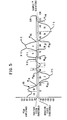
- Fig. 5 is an analog, hypothetical, waveform associated with a MICR character which is used to portray a variety of situations involved in reading characters;
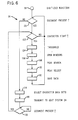
- Fig. 6 is a flow chart associated with the DAM shown in Fig. 4;
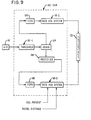
- Fig. 7 is a block diagram showing additional details of the matching module shown in Fig. 3;
- Fig. 8 is an analog hypothetical waveform used to portray different situations in a peak matching operation; and
- Fig. 9 is a block diagram showing a second embodiment of a Data Acquisition Module included in a First Pass Unit.
- Fig. 1 shows a portion of a
general banking system 10 in which this invention may be used. Thesystem 10 includes a First Pass Unit (FPU) 12, shown in dashed outline. The FPU 12 includes aMICR reader # 1 which is designated as 14, aData Acquisition Module 16, (referred to hereinafter as DAM 16), and a transport mechanism simply referred to astransport 18. TheReader # 1 in the FPU 12 performs the function of reading the MICR line of data on each record medium or banking check in the embodiment described. TheDAM 16 performs the function of acquiring data (as will be described hereinafter) from the record media, and thetransport 18 performs the function of receiving a batch of checks like 20 and moving them serially, in reading relationship with thereader 14 and thereafter moving them out of theFPU 12. - The MICR line of data which is read by the reader 14 (Fig. 1) and the data which is acquired by the
DAM 16 for each check of thebatch 20 of checks may be forwarded via aconventional interface 22 to a conventional host system designated generally as 24. Thehost system 24 includes an entry means 26, adisplay 28 for communicating with a user of thesystem 24, a Read Only Memory (ROM) 30 for storing instructions and programs, a processor (MP) 32 for performing operations, a Random Access Memory (RAM) 34, and control andinterface circuitry 36. As each check of thebatch 20 of checks is read by thereader 14, the associated MICR line of data and other data is processed by theReader # 1 and theDAM 16, and certain data is forwarded thereafter to theRAM 34 of thehost system 24 via theinterface 22. - The Data Acquisition Module (DAM 16) is shown in more detail in Fig. 4. Basically, the
DAM 16 receives data from thereader 14 and treats it in a special way (to be described hereinafter) and then forwards the derived data to thehost system 24 via theinterface 22. - The reader 14 (Fig. 1) provides the
DAM 16 with data on four different lines as shown. Thereader 14 is conventional and it includes, for example,logic circuitry 38 and an analog to digital (A/D)unit 40. Thelogic circuitry 38 also includes conventional circuits to interpret the MICR waveforms as thechecks 20 are moved in reading relationship with aread head 42. In the embodiments described, the MICR data is printed in a specific pattern such as an E13B font so that the MICR data or characters generate specific waveforms when they are read at a subsequent reading operation. The specific waveforms are digitized and compared conventionally with "templates" to produce numerical values or what are referred to as "recognition distances", which in effect, are used to identify the characters being read. These recognition distances are routed from thelogic circuitry 38 ofreader 14 to theDAM 16 over aline 44. Each time a document or check from thebatch 20 of checks comes into reading relationship with theread head 42, thelogic circuitry 38 produces a "document present" signal online 46. Similarly, each time a new character on a check comes into reading relationship with theread head 42, thelogic circuitry 38 produces a "character start" signal online 48. The A/D unit 40 produces a "digitized image" of each character read on theline 50. In the embodiment described, the sampling rate of the readhead 42 and the velocity with which thetransport 18 moves each check past the readhead 42 are such as to produce 128 samples for each character on a MICR line on the check. Naturally, the number of samples and sampling rate may be modified to suit particular applications. In the embodiment described, there are up to about 30 characters on a MICR line on each check. - Because the analog waveform of each MICR character can have both positive and negative values, as shown by the hypothetical waveform of Fig. 5, it is necessary that the corresponding digitized output from the A/
D unit 40 be capable of reflecting both positive and negative values. Accordingly, each of the 128 samples of digitized output from theAID unit 40 for each character is comprised of an eight bit byte, with the first bit of the byte denoting a positive or negative value, and the remaining seven bits denoting the sampled amplitude. In the embodiment described, a positive value is designated by a binary 0 and a negative value is designated by abinary 1. - The various outputs from the
reader 14 are forwarded to theDAM 16 overlines DAM 16 being shown in more detail in Fig. 4. - The DAM 16 (Fig. 4) includes a
conventional threshold circuit 52, a peak detector circuit 54, a First In, First Out memory unit hereinafter calledFIFO 56 and a Data Acquisition System designated generally as 58 and hereinafter calledDAS 58. - The threshold circuit 52 (Fig. 4) includes
conventional logic 60, acomparator 62 and anoutput 64. Thecomparator 62 is designed to produce an output other than zero atoutput 64 only when the amplitude of the digitized value in the byte of data coming from the A/D unit 40 is above 4 for positive values of the digitized data and is above 3 for negative values of the digitized data. Digitized amplitude values of the hypothetical waveform result in zero when they are less than the positive and negative threshold values mentioned. Normally, the same threshold values for positive and negative digitized amplitude values would be used; however, the different values used in this embodiment are used to overcome certain sensitivity deficiencies in theparticular read head 42 used. - In the embodiment described, 128 digitized samples (from sample #0 through sample #127) are outputted from the threshold circuit 52 (for each character on the MICR line being read by the read head 42) over
line 66 to the peak detector circuit 54. - The peak detector circuit 54 includes
logic circuitry 68 which receives the output from thethreshold circuit 52 and also includes afirst counter 70, asecond counter 72, asubtractor circuit 74, abuffer 76, and anoutput 78. The operation of the peak detector circuit 54 will be described hereinafter. - The
DAM 16 also includes theDAS 58 shown in Fig. 4. TheDAS 58 includes control andinterface circuitry 80, aROM 82 for providing control and sequencing, aRAM 84 for providing temporary storage during processing, and a processor referred to asMP 86. - To summarize, the
DAM 16 receives a digitized waveform from an associated analog waveform (similar tohypothetical analog waveform 86 shown in Fig. 5) for each of the 30 characters on a MICR line on each of the checks in a batch like 20 in the embodiment described. TheDAM 16 then selects 12 digitized waveforms (out of the 30 characters on a check) to be forwarded to theRAM 34 of thehost system 24. The 12 digitized waveforms selected are those which have the greatest "recognition distances". In essence, a recognition distance close to zero means that a particular character read conforms to the matching "template" for that character. A large recognition distance means that the character read does not conform to one of the character templates anticipated on the MICR line. A large recognition distance may be due to a "blemish" in the printing of that character, for example; however, this "blemish" is unique and can help to identify the particular check at a second or subsequent reading of that check. That is why those characters with the largest recognition distances are saved and used to identify the associated check in subsequent passes or readings. Each one of the checks in abatch 20 of checks has an identification number such as a MICR number like 88 (Fig. 2) which identifies the particular check, and it also has the associatedMICR waveform signature 90 forming part of adata string 92 which is stored in theRAM 34 of thehost system 24 for each of the checks in abatch 20. In the embodiment described, thewaveform signature 90 includes the 12 digitized waveforms (treated as hereinafter described) corresponding to the 12 characters out of 30 which are selected to identify the particular check when that check andbatch 20 of checks are processed later in another terminal or unit such as the Second Pass Unit 94 (SPU) shown in Fig. 3, and as described, generally, earlier herein. - As an aid in discussing the operation of the
DAM 16 shown in Figs. 1 and 4, it is beneficial to consider the associated process diagram orflow chart 96 shown in Fig. 6. The digitized waveform coming from thethreshold circuit 52 into thelogic 68 of the peak detector 54 is shown asstep 98 of theflow chart 96. Atstep 100, theDAM 16 looks for a document present signal as, for example, online 46 in Fig. 4 to ascertain whether or not a document or check is present at thereader 14. A document present signal activates theDAM 16. Assuming that a document or check is present, theDAM 16 then proceeds to step 102 to lookfor a character start signal (on line 48). If there is no character start signal, theDAM 16 returns to step 100 via the loop shown, and progresses to step 102 where theDAM 16 again looks for a character start signal. - Assuming that a character start signal occurs at
step 102 in Fig. 6, theDAM 16 starts to utilize the output from thethreshold circuit 52 as shown atstep 104. After thethresholding step 104, thestep 106 "open windows" is performed. - The
step 106, "open windows", refers to the process of providing "parameters" or "end points" between which a search is made for a peak or peaks which may be included therebetween. For example, with regard to thehypothetical waveform 86 shown in Fig. 5, awindow # 6 starts atsample # 72, the point at which the amplitude of the digitizedwaveform 86 rises above the positive fixed threshold level, and ends atsample # 86 at which the amplitude of thewaveform 86 drops below the threshold level. Within thewindow # 6, there are two peaks marked 6-1 and 6-2; the treatment of these peaks will be discussed hereinafter. - Similarly, windows exist for negative values of the waveform #86 (Fig. 5) as shown by the
window # 2 which starts atsample # 20 and ends atsample # 40, with a peak 2-1 occurring inwindow # 2. There are certain rules which are used to define or modify certain windows; these also will be discussed hereinafter. - As previously stated, there are 128 digitized samples (from #0 through #127) taken for each character in the embodiment described, and the sampling rate is 128K samples per second. The
counter 70 in Fig. 4 is used to provide a running count of the samples and is reset to zero with each new character start signal. Thecounter 72 in Fig. 4 is used to count the number of samples which occur within a window, and as previously described, each digitized sample is recorded as an eight bit byte. - When the start of a window occurs, the
subtractor 74 in the peak detector 54 (Fig. 4) is used to search for a peak located therein. This peak search (shown asstep 108 in Fig. 6) is performed by examining sequential samples as they are received in a window. For example, if the ith sample is larger than the previous sample (i-1), the slope is considered positive; if the jth sample is smaller or less than the previous sample (i-1), the slope is considered negative. A slope of zero occurs when two consecutive, or sequential samples have the same value; this would be represented by a flat horizontal line in thewaveform 86 shown in Fig. 5. When thesubtractor 74 indicates a change in the slope from positive or zero to negative, indicating that a peak has occurred, a signal is created which causes the peak detector 54 to save the peak value and its sample location (from counter 70) in thebuffer 76. It is possible that two peaks may exist within a window as shown by peaks 6-1 and 6-2 (Fig. 5) which exist in the window bounded by samples #72 and #86. Peaks also exist in the negative half of thewaveform 86. For example, the highest negative peak in thewindow # 2, which extends fromsample # 20 to sample #40, is peak 2-1. - There are also certain other situations handled by the peak detector 54 (Fig. 4) and represented by
peak search step 108 in Fig. 6. Thehypothetical waveform 86 shown in Fig. 5 relates to MICR characters as previously explained; consequently, because a MICR character always produces initially a positive-going pulse when read and ends with a negative-going peak, the first window always starts at sample #0, and the associated waveform has a positive value at that point. Another situation is that if the first opening or first window is greater or wider than 16 samples, the window is divided in half. The first window ends atsample # 18 in Fig 5 in the example portrayed. The first window is generally narrower than other windows because the character start circuitry (not shown) in thereader 14 will not indicate a "character start"signal 48 until the read head 42 (Fig. 1) is part way through the first peak of that waveform being read. In the example described, the first window (from sample #0-#18) is divided into two windows marked 1A and 1 B as shown in Fig. 5, with thefirst window 1A extending from sample #0 to sample #9 and thesecond window 1 B extending from sample #9 to sample #18. - Another situation handled by the peak detector 54 (Fig. 4) is that if a window has fewer than four samples included therein, the window is discarded as shown by window #3 in Fig. 5. For windows other than the first window, a window width larger than 20 samples is divided into two windows as shown by the
windows sample # 88 to sample #116. Because there is no slope reversal or peak inwindow 7A, this window data may be discarded; the peak 7-1 inwindow 7B is saved. - Another situation handled by the peak detector 54 (Fig. 4) is that of a "flat peak" as shown by
window # 5 in Fig. 5. As soon aswindow # 5 is opened, the amplitude values from thereader 14 remain substantially constant so as to produce no change in slope for most of the width of the window. Finally, thesubtractor 74 ascertains that there is a negative slope atsample # 62 as the peak amplitude falls below the threshold value to closewindow # 5. Thelogic 68, associated with the peak detector 54, will then position the "peak" at the center of thewindow # 5 after ascertaining the number of samples in the window (from the count in counter 72). The sample number at the center ofwindow # 5 along with the "peak" value are then stored in thebuffer 76. - Some additional comments with regard to the
peak search step 108 in Fig. 6 are necessary. In a situation like the one portrayed inwindow 1A in Fig. 5 in which thewaveform 86 is positive, there is no positive peak therein; another way of stating it is that the slope of thewaveform 86 never changes from a positive slope to a negative slope in thewindow 1A, as it starts out at sample #0 (the first one) as a negative slope. In this situation, the digitized value of thewaveform 86 located at sample #0 becomes the first "peak" value in the first window. This procedure applies only to the first positive window in the waveforms; all other windows require a change of slope to locate a peak. It should be recalled that thewaveform 86 for each MICR character always starts in a positive direction and always ends with thewaveform 86 on the negative side going towards the positive side as shown bywindow 7B. - After all the peak values for a character have been determined the next step associated with the peak detector 54 (fig. 4) is to select the peak or peaks to be saved for that character as shown by the peak
select step 110 in Fig. 6. In general, the peak detector 54 selects a maximum of 3 peaks and a minimum of 1 peak in each of the positive and negative halves of the associated waveform like 86 in Fig. 5. As an aid in reducing the number of peaks prior to selecting the peaks to be representative of the associated character, thelogic 68 of the peak detector 54 will examine the sample number (i.e. location) of each of the stored peaks and will discard that peak which is within 10 samples of a nearby peak and also is the smaller of the two peaks. It should be recalled that at this time the digitized value of a peak amplitude (consisting of seven bits for its numerical value and one bit relating to its being positive or negative) and the sample number or location of the peak are stored in thebuffer 76. After a count of 127 (in the embodiment described) is obtained oncounter 70, indicating the end of a character being read, thelogic 68 withdraws the peaks from thebuffer 76 and arranges them in descending order of peak amplitude to begin the selection of peaks associated withstep 110. Thereafter, thelogic 68 performs certain operations on the ranked peaks. If the largest peak (for positive values) has a value which is four times greater than the second largest peak, then only the largest peak is saved and the remaining peaks are discarded. This is done because due to the nature of the MICR waveform, the second and smaller peaks are probably only noise peaks in this situation. If the second peak is larger than one fourth of the size of the largest peak, then the second peak is saved. If a third peak exists, in order to be saved it must be larger than the sum of the first and second largest peaks divided by five, otherwise it is discarded. It should be noted that because there are both positive and negative halves, there will be a maximum of 6 peaks and a minimum of 2 peaks saved for each character being read in the example described. - After the peaks or peak values are selected as represented by the peak
select step 110 in Fig. 6, they are outputted from the output 78 (Fig. 4) and are stored in theFIFO 56 as represented by thestep 112. TheFIFO 56 is a memory device which is arranged to sequentially store the peak values saved along with their sample locations for each character being read. Fromstep 112 in Fig. 6, the routine returns to step 100 to repeat the process described for a new or the next character. - At the time that peak values are being ascertained and stored as just described for each character, the recognition distance for each character scanned at the
reader 14 is calculated therein and forwarded overline 44 to the DAS 58 (Fig. 4) where it is stored in theRAM 84 therein. After all the MICR characters are read on the document passing through thereader 14, a point will be reached at which the document will no longer be present atstep 100 in Fig. 6. Fromstep 100, the routine proceeds to step 114 at which the 12 "characters" or data sets out of 30 characters (in the embodiment described) are selected to identify the associated document. The 12 characters selected are those which have the greatest recognition distances as previously explained; these are the ones that are most expressive of uniqueness of the associated document. A conventional software routine stored in the ROM 82 (Fig. 4) may be used to select the 12 characters out of 30. After the 12 characters are selected, the corresponding peak value data located in theFIFO 56 is then selected and transferred (instep 116 in Fig. 6) from the control andinterface circuitry 80 of the DAS 58 (via the interface 22) to thehost system 24 where the data is stored in theRAM 34 therein. When a new document is presented to thereader 14, and a new document present signal is generated as atstep 118 in Fig. 6, the routine shown therein returns to step 102 to repeat the process desscribed for the first character to be read on the new document. It also should be recalled that the data stored in theRAM 34 for each of the 12 characters selected for each document includes the peak values and their associated sample numbers; this data, referred to as the MICR waveform signature 90 (Fig. 2), is included for each of the documents in a batch (like 20) of documents along with theMICR # 88 for that document. TheMICR # 88 is developed conventionally from the recognition distances. - When the
batch 20 of documents is to be read again, it is passed through a reader as was done in Fig. 1. Such a reader like 120 in Fig. 3 may be part of the second pass unit (SPU) 94 as previously explained. To show how the second reading of thebatch 20 may be utilized, it is customary to print or encode in MICR printing the monetary amount of each check on the check itself. The monetary amount of the check may be entered into thehost system 24 conventionally as by manual entry. An operation which theSPU 94 performs is to encode in MICR printing the associated monetary amounts on the checks in abatch 20 as previously stated. A conventional encoder andsorter 122 is used to encode the amount on a check. It is important that the correct monetary amount be encoded on the appropriate check. Each of the checks is moved in reading relationship withMICR reader 120 by aconventional transport 124 which subsequently also moves each of the checks in printing relationship with the encoder andsorter 122. Those checks which are properly identified are encoded and exited from theSPU 94 via the encoder andsorter 122 to form an encoded batch 20-1 of checks. Those checks which are not properly identified, for example, are exited from the encoder andsorter 122 to form a reject batch 20-2 of checks. - The waveform matching at the SPU 94 (Fig. 3) is effected in conjunction with a
matching module 126. Basically, the function of thematching module 126 is to receive the first pass data retained in thehost system 24 from the FPU 12 (which data is referred to as reference data) and compare the reference data with the second pass data developed in the SPU 94 (which data is referred to as test data). When the test data matches the reference data, thematching module 126 indicates a "match" to the encoder andsorter 122 to enable the encoder to print data on the particular check just read at thereader 120 in the embodiment described. If no match between reference and test data occurs, the particular check just read is rejected by the encoder andsorter 122 to batch 20-2 as previously described. - The SPU 94 (Fig. 3) is coupled to the
host system 24 via aconventional interface 128, and theSPU 94 also includes a conventionalSPU processing system 130, which includes control andinterface circuitry 132, aROM 134 for storing the associated programs, aRAM 136, and a processor (MP) 138. Suitable lines (not shown) extend from the control andinterface circuitry 132 to theMICR reader 120,transport 124, and encoder andsorter 122 to provide conventional control where necessary or desirable. - The matching module 126 (Fig. 3) is shown in more detail in Fig. 7, and it includes a
peak detector 140 which is identical to the peak detector 54 (Fig. 4) already described. Thepeak detector 140 includeslogic 142, counters 144 and 146, asubtractor 148, abuffer 150 and anoutput 152 which all function in the same manner as do the corresponding elements already described with regard to peak detector 54. - The matching module 126 (Fig. 7) also includes a module control designated generally as 154 and which includes a
RAM 156, a ROM 158 (for storing instructions), a processor (MP) 160, and control andinterface circuitry 162. - When the
batch 20 of checks is to be passed through theSPU 94, some conventional preliminary work is done first. For example, a header card (not shown) but associated with thebatch 20 of checks may be used to access the appropriate data strings 92 (Fig. 2) from thehost system 24. When thebatch 20 of checks is to be passed through thereader 120 in theSPU 94, the SPU system 130 (Fig. 7) downloads the data strings 92 to themodule control 154 where they are momentarily stored in theRAM 156; this is the reference data as previously described, and it is transferred just prior to what is expected to be data from the same document derived from the readhead 162 of thereader 120. Thelogic circuitry 164 of thereader 120 produces a document present signal online 166, and also may produce the associated recognition distance online 168, which lines 166 and 168 are coupled to themodule control 154 for use thereby. A character start signal developed by thelogic circuitry 164 is utilized by thepeak detector 140 as previously explained with regard to peak detector 54. An A/D converter 170 converts the analog waveform read from the MICR line at the readhead 162 to a digitized output which is forwarded to thelogic 142 of thepeak detector 140. The output of the A/D 170 is not thresholded prior to entering the associatedpeak detector 140 as was done in theFPU 12. Thepeak detector 140 produces peaks or the "test data" for each character on the associated MICR line of data on a check being read in the same manner with regard to peak determination as was done with the peak detector 54 in theFPU 16. The test data or peaks for each of the characters are forwarded from thepeak detector 140 to theFIFO memory 172. This test data or peak data includes its discrete value as previously described and its associated sample number which is intrinsically located or positioned in theFIFO memory 172 whose output is fed into themodule control 154. - It should be recalled that the peaks associated with only 12 characters out of a total of 30 characters for a check are used as reference data (in the example described) to identify the check in the waveform matching technique disclosed herein. If, for example, the first character selected as reference data were the 4th out of 30 characters, the associated reference data would be located in the
RAM 156 of the module control 154 (Fig. 7). The test data or peaks coming from theFIFO memory 172 for the first three characters are disregarded by themodule control 154, and the direct waveform matching begins when the test data for the fourth character arrives at themodule control 154. - Continuing with the example just given, the reference data or peaks for the 4th character are used to open up search windows with regard to the incoming test data or peaks from the FIFO memory 172 (Fig. 7). In other words if a reference peak occurs at sample #14 (out of 128 samples), one would except a similar peak to be found at
sample # 14 in the test data. Because there may be some variation in the sensitivities of the readers in the associatedFPU 12 and theSPU 94 and the speeds of their associatedtransports 
- WB=window boundary, and
- X,¡=the ith reference peak.
- The brackets within the parenthesis of Eq. 1 indicate that the values within the brackets may be changed as a result of experimentation or for different applications. As an illustration of Eq. 1, the window boundaries for
sample # 40 are given by:
- Notice that with Eq. 1, the window size increases as the reference peak location increases. In other words,
reference sample # 120, for example, has a wider window thanreference sample # 20. By allowing the window size to increase as the reference peak location increases, variations in the speeds of thetransports matching module 126 to find the test peaks. - There are some other factors which affect the determination of the search window boundaries; they are:
- (1) The leading boundary of a search window may not precede the start of a character, and the trailing boundary of a search window may not exceed 127 samples from the start of a character in the embodiment described;
- (2) The leading boundary of a search window may not precede a previously detected peak, so that when two reference peaks are located close to each other, the same test peak will not be selected twice; and
- (3) When the MICR line of data on the checks is printed with a low-intensity ink, it is necessary to expand the window size because the peaks produced by the low-intensity ink are generally low and poorly defined. Accordingly, if a reference peak for a particular sample # has a value of a predetermined amount, as for example when the reference peak value is less than or equal to 7 in the embodiment described, the window boundary limits are given by the following equation:

- To review, the window boundaries have been determined from the reference data in order to search for the test data or peaks. The peak detector 140 (Fig. 7) calculates or determines the peaks in the same general manner as does peak detector 54 (Fig. 4) already described. Assuming that the checks in a batch of checks are in the proper order, the test peaks obtained from the
SPU 94 should match the reference peaks obtained from theFPU 12. - While a test peak may be found in a window boundary derived from the reference data or peaks, the waveform matching of this invention also includes some additional steps or operations which evaluate the amount by which a test peak varies from its reference location and value. The steps may be generally described as follows:
- (1) The amount by which a test peak varies from its reference location and value, respectively, are referred to generally as the "x" or position difference (distance) and the "y" or amplitude difference (distance).
- (2) The x and y distances are developed for each character, and then, an "overall distance" is calculated (by certain steps to be hereinafter described) for each character.
- (3) the "overall distance" for each character along with certain other criteria are used in developing "acceptance" or "rejection" criteria in deciding whether or not a match exists, i.e., Is the check in the
SPU 94 the check corresponding to that one which produced the reference data from theFPU 12? - The development of the x position distances and the y amplitude distances can be more readily understood in connection with Fig. 8. First, a tolerance box is constructed around each of the reference peak points and the test peak points according to the following formulae:


- y is equal to the peak value, and
- x is equal to the peak position (sample number).
- Fig. 8 shows tolerance boxes which are constructed around reference data peaks and test data peaks associated with an
illustrative waveform 174. A box designated as R-1 is associated with a reference data peak and the box designated T-1 is associated with a test data peak, and similarly, the box designated R-2 is associated with a reference data peak and the box designated T-2 is associated with a test data peak. Note from Eq. 4 that the x limits of the tolerance boxes are fixed; however, these values can be changed readily if field trials indicate the need to do so. Note, also, that a reference data peak is marked with an "x" in Fig. 8, and a test data peak is marked with a plus (+) sign. - After the tolerance boxes have been constructed for the reference data peaks and the test data peaks for the x and y directions, the distances between these tolerance boxes are calculated separately. The general rule is that the distance between the reference and test data peaks is calculated by subtracting the test data peak from the reference data peak. The result may be either positive or negative depending upon which data peak is the larger of the two. If the tolerance boxes of the reference and test peak data values overlap or touch in one direction, the distance in that direction is zero. With regard to
waveform 174 in Fig. 8, because the reference data peak R-1 and the test data peak T-1 overlap in the x direction, for example, the distance in the x direction or Ax is equal to zero. An example of a Ay distance is shown withreference numeral 176 in Fig. 8. An example of a Ax distance is shown withreference numeral 177 which shows the distance between reference data peak R-2 and test data peak T-2. - When all the peaks have been found in the test data, and the x and y distances therefor have been calculated as just explained, an overall distance for each character is generated by the following formulae:


- n=the total number of peaks in the character, positive and negative combined;
- Δx1=the positional distance calculated as just described for the ith peak; and
- Δy1=the amplitude distance calculated as just described for the it" peak.
- The term within the brackets in Eq. 5 serves to subtract out or to reduce constant positional shifts caused by "character start" variations associated with the readers (like 14) involved. Similarly, the term within the brackets in Eq. 6 serves to subtract out or to reduce constant amplitude shift caused by a DC offset in the associated readers. Eq. 7 is simply a total of Dx and Dy.
- Some additional comments seem appropriate with regard to the various equations just reviewed. In the event that no test peak is discovered within a window as previously described, no distance is accumulated. In this situation, a separate counter (not shown) but associated with the
module control 154 is incremented, and the count itself is used as one of the overall acceptance/rejection criteria to be later described herein. - The entire process of test peak searching and distance calculation associated with Equations 1-7 already described is repeated for each of the 12 characters (out of 30) selected to identify a particular check in the
SPU 94. After the distances for each character are obtained, the following quantities are calculated: - (1) The average distance for each character;
- (2) The average distance in the y direction for only that character which has the largest total distance; and
- (3) The standard deviation of the distance in the y direction namely Δy1 for that character defined in (2) above.
- After the above quantities are calculated, a final step in the waveform matching of this invention is begun. The final step is to apply a set of tests which will allow a pass/fail decision to be made by the
matching module 126. The pass/fail decision is made by thematching module 126 with regard to a check which is located at the encoder and sorter 122 (Fig. 3). In the embodiment described, the particular check is encoded with the associated monetary amount if a pass decision is made. If a fail decision is made, the check is rejected into batch 20-2. - The tests for the pass/fail decision are handled by module control 154 (Fig. 7) in the following order:
- 1. Reject the check if the total number of unmatchable peaks over all the 12 characters is greater than <0>.
- 2. Accept or pass the check if the average distance per character is -<2.0>.
- 3. Reject the check if the average distance per character is ><20.0>.
- 4. Perform the following tests on the character having the largest distance:
- (a) Pass the check if the DTotal distance is <<25>.
- (b) Pass the check if the average distance for the features (Δy) of this character in the y direction only is <3.0.
- (c) Pass the check if the ratio of the standard deviation (previously calculated) to the average distance for the y direction features (from (b) above) is ≤1.5; otherwise, reject the check.
- In the embodiment described, when a check is identified by the matching module 126 (Fig. 3) as being the expected one, the monetary amount for that check is transferred to the encoder and
sorter 122 via line 178 (Fig. 3) from the SPU system 130 (Fig. 3) while the processor 160 (Fig. 7) associated with thematching module 126 will indicate that a match is had vialine 180. - Fig. 9 shows a second embodiment of a Data Acquisition Module (DAM) designated generally as 182 which may be included in a First Pass Unit (FPU) such as 12 shown in Fig. 1. The
DAM 182 receives the output from the A/D unit 40 of the reader 14 (Fig. 1) and accepts it in a threshold circuit 52-1 which is identical to 52 shown in Fig. 4. The output from the threshold circuit 52-1 is fed into astandard DEMUX circuit 184 which separates the values ofwaveform 86 into positive values which are stored in a First In, First Out memory unit (FIFO) 186 by sample number and routes the negative values ofwaveform 86 to arectifier 188. Therectifier 188 converts the negative values of thewaveform 86 into positive values which are stored in a First In, First Out memory unit (FIFO) 190 by sample number. The output of theFIFO 186 is fed into a Data Acquisition System (DAS) 58-1 which is similar to DAS 58 (Fig. 4). Similarly, the output ofFIFO 190 is fed into a Data Acquisition System (DAS) 58-2 which is also similar toDAS 58. The DAS 58-1 and the DAS 58-2 then perform (via software) the various functions already explained with regard to the peak detector 54 (Fig. 4). The data for the 12 characters selected (out of 30) to identify a particular check or document is then forwarded to theinterface 22 which forwards the data to thehost system 24 as previously described. The various equations mentioned earlier herein may be implemented by software associated with the DAS 58-1 and 58-2. One of the two DASs like 58-2 may be used for obtaining the recognition distances and a document present signal as previously explained.
Claims (9)
Applications Claiming Priority (2)
| Application Number | Priority Date | Filing Date | Title |
|---|---|---|---|
| US06/431,923 US4547899A (en) | 1982-09-30 | 1982-09-30 | Waveform matching system and method |
| US431923 | 1995-04-28 |
Publications (2)
| Publication Number | Publication Date |
|---|---|
| EP0120080A1 EP0120080A1 (en) | 1984-10-03 |
| EP0120080B1 true EP0120080B1 (en) | 1987-07-22 |
Family
ID=23714011
Family Applications (1)
| Application Number | Title | Priority Date | Filing Date |
|---|---|---|---|
| EP83903343A Expired EP0120080B1 (en) | 1982-09-30 | 1983-09-28 | Method and system for identifying documents |
Country Status (6)
| Country | Link |
|---|---|
| US (1) | US4547899A (en) |
| EP (1) | EP0120080B1 (en) |
| JP (1) | JPS59501843A (en) |
| CA (1) | CA1188812A (en) |
| DE (1) | DE3372678D1 (en) |
| WO (1) | WO1984001455A1 (en) |
Families Citing this family (39)
| Publication number | Priority date | Publication date | Assignee | Title |
|---|---|---|---|---|
| JPS61177592A (en) * | 1985-02-01 | 1986-08-09 | アイエム電子株式会社 | Type discriminator for printed matter |
| US4797938A (en) * | 1985-10-15 | 1989-01-10 | International Business Machines Corporation | Method of identifying magnetic ink (MICR) characters |
| US4906988A (en) * | 1987-01-27 | 1990-03-06 | Rand Mcnally & Co. | Object verification system and method |
| US5054092A (en) * | 1988-03-31 | 1991-10-01 | Checkmate Electronics, Inc. | Hand-operated low cost magnetic character recognition system |
| JPH01295391A (en) * | 1987-06-24 | 1989-11-29 | I M Denshi Kk | Identifying device for printed matter |
| US4776021A (en) * | 1987-11-16 | 1988-10-04 | Ncr Corporation | Speed compensation scheme for reading MICR data |
| US5237620A (en) * | 1989-05-01 | 1993-08-17 | Credit Verification Corporation | Check reader method and system for reading check MICR code |
| US5644723A (en) | 1989-05-01 | 1997-07-01 | Credit Verification Corporation | Method and system for selective incentive point-of-sale marketing in response to customer shopping histories |
| US8700458B2 (en) | 1989-05-01 | 2014-04-15 | Catalina Marketing Corporation | System, method, and database for processing transactions |
| US5649114A (en) | 1989-05-01 | 1997-07-15 | Credit Verification Corporation | Method and system for selective incentive point-of-sale marketing in response to customer shopping histories |
| US5201010A (en) * | 1989-05-01 | 1993-04-06 | Credit Verification Corporation | Method and system for building a database and performing marketing based upon prior shopping history |
| US5305196A (en) * | 1989-05-01 | 1994-04-19 | Credit Verification Corporation | Check transaction processing, database building and marketing method and system utilizing automatic check reading |
| US5621812A (en) | 1989-05-01 | 1997-04-15 | Credit Verification Corporation | Method and system for building a database for use with selective incentive marketing in response to customer shopping histories |
| US5034985A (en) * | 1989-11-13 | 1991-07-23 | Pitney Bowes Inc. | Matched mailing system employing address print array recognition |
| US5026974A (en) * | 1989-12-27 | 1991-06-25 | Ncr Corporation | Method for recognizing the leading edge of a character in E13B font |
| US6179484B1 (en) * | 1991-07-18 | 2001-01-30 | International Business Machines Corp. | Two-pass document image processing method and system |
| US6400996B1 (en) | 1999-02-01 | 2002-06-04 | Steven M. Hoffberg | Adaptive pattern recognition based control system and method |
| US6418424B1 (en) | 1991-12-23 | 2002-07-09 | Steven M. Hoffberg | Ergonomic man-machine interface incorporating adaptive pattern recognition based control system |
| US8352400B2 (en) | 1991-12-23 | 2013-01-08 | Hoffberg Steven M | Adaptive pattern recognition based controller apparatus and method and human-factored interface therefore |
| US7242988B1 (en) | 1991-12-23 | 2007-07-10 | Linda Irene Hoffberg | Adaptive pattern recognition based controller apparatus and method and human-factored interface therefore |
| US5903454A (en) | 1991-12-23 | 1999-05-11 | Hoffberg; Linda Irene | Human-factored interface corporating adaptive pattern recognition based controller apparatus |
| US6850252B1 (en) | 1999-10-05 | 2005-02-01 | Steven M. Hoffberg | Intelligent electronic appliance system and method |
| US10361802B1 (en) | 1999-02-01 | 2019-07-23 | Blanding Hovenweep, Llc | Adaptive pattern recognition based control system and method |
| US6292786B1 (en) | 1992-05-19 | 2001-09-18 | Incentech, Inc. | Method and system for generating incentives based on substantially real-time product purchase information |
| ES2078852B1 (en) * | 1993-08-02 | 1996-07-16 | Azkoyen Ind Sa | "PROCEDURE AND DEVICE FOR THE HIGH SPEED MEASUREMENT AND CHARACTERIZATION OF MAGNETIC MATERIALS" |
| US6327378B1 (en) | 1995-02-15 | 2001-12-04 | Banctec, Inc. | Character recognition method |
| US8364136B2 (en) | 1999-02-01 | 2013-01-29 | Steven M Hoffberg | Mobile system, a method of operating mobile system and a non-transitory computer readable medium for a programmable control of a mobile system |
| US7904187B2 (en) | 1999-02-01 | 2011-03-08 | Hoffberg Steven M | Internet appliance system and method |
| US6609104B1 (en) | 1999-05-26 | 2003-08-19 | Incentech, Inc. | Method and system for accumulating marginal discounts and applying an associated incentive |
| US6993498B1 (en) | 1999-07-15 | 2006-01-31 | Midnight Blue Remote Access, Llc | Point-of-sale server and method |
| US6769615B2 (en) * | 2002-04-26 | 2004-08-03 | Software Corporation International | Multi-pass merge process for the check processing control system |
| WO2004063966A2 (en) * | 2003-01-11 | 2004-07-29 | Magtek, Inc. | Check imaging device |
| US7474780B2 (en) * | 2003-08-30 | 2009-01-06 | Opex Corp. | Method and apparatus for determining unknown magnetic ink characters |
| US20070038455A1 (en) * | 2005-08-09 | 2007-02-15 | Murzina Marina V | Accent detection and correction system |
| US8023718B1 (en) * | 2007-01-16 | 2011-09-20 | Burroughs Payment Systems, Inc. | Method and system for linking front and rear images in a document reader/imager |
| US8023717B1 (en) * | 2007-01-16 | 2011-09-20 | Burroughs Payment Systems, Inc. | Method and system for processing backwards documents in a document reader/imager |
| DE102007019107A1 (en) * | 2007-04-23 | 2008-10-30 | Giesecke & Devrient Gmbh | Method and device for checking value documents |
| ATE510392T1 (en) * | 2008-09-12 | 2011-06-15 | Research In Motion Ltd | TIME SYNCHRONIZATION OF LONG-TERM EVOLUTION RADIO CONNECTIONS |
| US8116394B2 (en) | 2008-09-12 | 2012-02-14 | Research In Motion Limited | Long term evolution (LTE) radio link timing synchronization |
Family Cites Families (9)
| Publication number | Priority date | Publication date | Assignee | Title |
|---|---|---|---|---|
| GB1243969A (en) * | 1967-11-15 | 1971-08-25 | Emi Ltd | Improvements relating to pattern recognition devices |
| US3938089A (en) * | 1974-02-25 | 1976-02-10 | Burroughs Corporation | Double read system for character recognition systems |
| FR2358708A1 (en) * | 1976-07-15 | 1978-02-10 | Cii Honeywell Bull | IMPROVEMENTS TO PRINTED CHARACTER RECOGNITION SYSTEMS |
| US4087789A (en) * | 1977-04-27 | 1978-05-02 | Burroughs Corporation | Magnetic ink character recognition system |
| US4143355A (en) * | 1977-08-29 | 1979-03-06 | Signature Guardian Systems, Inc. | Character recognition system |
| US4148010A (en) * | 1977-10-31 | 1979-04-03 | Ncr Canada Ltd. - Ncr Canada Ltee | Magnetic ink character reader system |
| US4143356A (en) * | 1977-10-31 | 1979-03-06 | Ncr Canada Ltd - Ncr Canada Ltee | Character recognition apparatus |
| US4277775A (en) * | 1979-10-01 | 1981-07-07 | Ncr Canada Ltd - Ncr Canada Ltee | Character recognition system |
| EP0026669B1 (en) * | 1979-10-01 | 1985-05-22 | Ncr Canada Ltd - Ncr Canada Ltee | Character recognition apparatus and method, using waveform analysis |
-
1982
- 1982-09-30 US US06/431,923 patent/US4547899A/en not_active Expired - Lifetime
-
1983
- 1983-09-28 DE DE8383903343T patent/DE3372678D1/en not_active Expired
- 1983-09-28 WO PCT/US1983/001507 patent/WO1984001455A1/en active IP Right Grant
- 1983-09-28 EP EP83903343A patent/EP0120080B1/en not_active Expired
- 1983-09-28 JP JP58503402A patent/JPS59501843A/en active Pending
- 1983-09-29 CA CA000438037A patent/CA1188812A/en not_active Expired
Also Published As
| Publication number | Publication date |
|---|---|
| JPS59501843A (en) | 1984-11-01 |
| CA1188812A (en) | 1985-06-11 |
| EP0120080A1 (en) | 1984-10-03 |
| WO1984001455A1 (en) | 1984-04-12 |
| DE3372678D1 (en) | 1987-08-27 |
| US4547899A (en) | 1985-10-15 |
Similar Documents
| Publication | Publication Date | Title |
|---|---|---|
| EP0120080B1 (en) | Method and system for identifying documents | |
| JP3842006B2 (en) | Form classification device, form classification method, and computer-readable recording medium storing a program for causing a computer to execute these methods | |
| US5134663A (en) | Center line magnetic ink character recognition system | |
| JP2575539B2 (en) | How to locate and identify money fields on documents | |
| US4143356A (en) | Character recognition apparatus | |
| US4685141A (en) | Method and system for finding image data associated with the monetary amount on financial documents | |
| US4797938A (en) | Method of identifying magnetic ink (MICR) characters | |
| US4245211A (en) | MICR Waveform analyzer | |
| EP0344742A2 (en) | Courtesy amount read and transaction balancing system | |
| US5805740A (en) | Bar-code field detecting apparatus performing differential process and bar-code reading apparatus | |
| CA2028707C (en) | Method for recognizing the leading edge of a character in e13b font | |
| US20080123933A1 (en) | Method and apparatus for magnetic character recognition | |
| US6481624B1 (en) | Method and apparatus for processing documents to distinguish various types of documents | |
| US6179484B1 (en) | Two-pass document image processing method and system | |
| US4490853A (en) | Matrix character reading system | |
| Tou et al. | Automatic recognition of handwritten characters via feature extraction and multi-level decision | |
| EP0446633A2 (en) | Document processor including method and apparatus for identifying and correcting errors | |
| US6445808B1 (en) | Method and apparatus for detecting credit/debit cards in connection with the processing of bulk mail | |
| JPS6316795B2 (en) | ||
| EP0073113A1 (en) | Document processing system | |
| JP3105918B2 (en) | Character recognition device and character recognition method | |
| JP3374762B2 (en) | Character recognition method and apparatus | |
| JP2003271955A (en) | Identifier and method for identifying certificate stamp | |
| JP2571236B2 (en) | Character cutout identification judgment method | |
| JPH0793466A (en) | Device for discriminating character kind and method therefor |
Legal Events
| Date | Code | Title | Description |
|---|---|---|---|
| PUAI | Public reference made under article 153(3) epc to a published international application that has entered the european phase |
Free format text: ORIGINAL CODE: 0009012 |
|
| AK | Designated contracting states |
Designated state(s): DE FR GB |
|
| 17P | Request for examination filed |
Effective date: 19841005 |
|
| DET | De: translation of patent claims | ||
| GRAA | (expected) grant |
Free format text: ORIGINAL CODE: 0009210 |
|
| AK | Designated contracting states |
Kind code of ref document: B1 Designated state(s): DE FR GB |
|
| REF | Corresponds to: |
Ref document number: 3372678 Country of ref document: DE Date of ref document: 19870827 |
|
| ET | Fr: translation filed | ||
| PLBE | No opposition filed within time limit |
Free format text: ORIGINAL CODE: 0009261 |
|
| STAA | Information on the status of an ep patent application or granted ep patent |
Free format text: STATUS: NO OPPOSITION FILED WITHIN TIME LIMIT |
|
| 26N | No opposition filed | ||
| PGFP | Annual fee paid to national office [announced via postgrant information from national office to epo] |
Ref country code: FR Payment date: 19890630 Year of fee payment: 7 |
|
| PGFP | Annual fee paid to national office [announced via postgrant information from national office to epo] |
Ref country code: GB Payment date: 19890731 Year of fee payment: 7 |
|
| PGFP | Annual fee paid to national office [announced via postgrant information from national office to epo] |
Ref country code: DE Payment date: 19891002 Year of fee payment: 7 |
|
| PG25 | Lapsed in a contracting state [announced via postgrant information from national office to epo] |
Ref country code: GB Effective date: 19900928 |
|
| GBPC | Gb: european patent ceased through non-payment of renewal fee | ||
| PG25 | Lapsed in a contracting state [announced via postgrant information from national office to epo] |
Ref country code: FR Effective date: 19910530 |
|
| PG25 | Lapsed in a contracting state [announced via postgrant information from national office to epo] |
Ref country code: DE Effective date: 19910601 |
|
| REG | Reference to a national code |
Ref country code: FR Ref legal event code: ST |