EP0119848A2 - Anastomotic coupling device - Google Patents
Anastomotic coupling device Download PDFInfo
- Publication number
- EP0119848A2 EP0119848A2 EP84301797A EP84301797A EP0119848A2 EP 0119848 A2 EP0119848 A2 EP 0119848A2 EP 84301797 A EP84301797 A EP 84301797A EP 84301797 A EP84301797 A EP 84301797A EP 0119848 A2 EP0119848 A2 EP 0119848A2
- Authority
- EP
- European Patent Office
- Prior art keywords
- sleeve
- cuffs
- cuff
- tubular member
- inverted
- Prior art date
- Legal status (The legal status is an assumption and is not a legal conclusion. Google has not performed a legal analysis and makes no representation as to the accuracy of the status listed.)
- Withdrawn
Links
Images
Classifications
-
- A—HUMAN NECESSITIES
- A61—MEDICAL OR VETERINARY SCIENCE; HYGIENE
- A61B—DIAGNOSIS; SURGERY; IDENTIFICATION
- A61B17/00—Surgical instruments, devices or methods, e.g. tourniquets
- A61B17/11—Surgical instruments, devices or methods, e.g. tourniquets for performing anastomosis; Buttons for anastomosis
- A61B17/1114—Surgical instruments, devices or methods, e.g. tourniquets for performing anastomosis; Buttons for anastomosis of the digestive tract, e.g. bowels or oesophagus
-
- A—HUMAN NECESSITIES
- A61—MEDICAL OR VETERINARY SCIENCE; HYGIENE
- A61B—DIAGNOSIS; SURGERY; IDENTIFICATION
- A61B17/00—Surgical instruments, devices or methods, e.g. tourniquets
- A61B2017/00004—(bio)absorbable, (bio)resorbable, resorptive
-
- A—HUMAN NECESSITIES
- A61—MEDICAL OR VETERINARY SCIENCE; HYGIENE
- A61F—FILTERS IMPLANTABLE INTO BLOOD VESSELS; PROSTHESES; DEVICES PROVIDING PATENCY TO, OR PREVENTING COLLAPSING OF, TUBULAR STRUCTURES OF THE BODY, e.g. STENTS; ORTHOPAEDIC, NURSING OR CONTRACEPTIVE DEVICES; FOMENTATION; TREATMENT OR PROTECTION OF EYES OR EARS; BANDAGES, DRESSINGS OR ABSORBENT PADS; FIRST-AID KITS
- A61F2/00—Filters implantable into blood vessels; Prostheses, i.e. artificial substitutes or replacements for parts of the body; Appliances for connecting them with the body; Devices providing patency to, or preventing collapsing of, tubular structures of the body, e.g. stents
- A61F2/02—Prostheses implantable into the body
- A61F2/30—Joints
- A61F2002/30001—Additional features of subject-matter classified in A61F2/28, A61F2/30 and subgroups thereof
- A61F2002/30316—The prosthesis having different structural features at different locations within the same prosthesis; Connections between prosthetic parts; Special structural features of bone or joint prostheses not otherwise provided for
- A61F2002/30329—Connections or couplings between prosthetic parts, e.g. between modular parts; Connecting elements
- A61F2002/30476—Connections or couplings between prosthetic parts, e.g. between modular parts; Connecting elements locked by an additional locking mechanism
- A61F2002/305—Snap connection
-
- A—HUMAN NECESSITIES
- A61—MEDICAL OR VETERINARY SCIENCE; HYGIENE
- A61F—FILTERS IMPLANTABLE INTO BLOOD VESSELS; PROSTHESES; DEVICES PROVIDING PATENCY TO, OR PREVENTING COLLAPSING OF, TUBULAR STRUCTURES OF THE BODY, e.g. STENTS; ORTHOPAEDIC, NURSING OR CONTRACEPTIVE DEVICES; FOMENTATION; TREATMENT OR PROTECTION OF EYES OR EARS; BANDAGES, DRESSINGS OR ABSORBENT PADS; FIRST-AID KITS
- A61F2220/00—Fixations or connections for prostheses classified in groups A61F2/00 - A61F2/26 or A61F2/82 or A61F9/00 or A61F11/00 or subgroups thereof
- A61F2220/0025—Connections or couplings between prosthetic parts, e.g. between modular parts; Connecting elements
-
- A—HUMAN NECESSITIES
- A61—MEDICAL OR VETERINARY SCIENCE; HYGIENE
- A61F—FILTERS IMPLANTABLE INTO BLOOD VESSELS; PROSTHESES; DEVICES PROVIDING PATENCY TO, OR PREVENTING COLLAPSING OF, TUBULAR STRUCTURES OF THE BODY, e.g. STENTS; ORTHOPAEDIC, NURSING OR CONTRACEPTIVE DEVICES; FOMENTATION; TREATMENT OR PROTECTION OF EYES OR EARS; BANDAGES, DRESSINGS OR ABSORBENT PADS; FIRST-AID KITS
- A61F2310/00—Prostheses classified in A61F2/28 or A61F2/30 - A61F2/44 being constructed from or coated with a particular material
- A61F2310/00005—The prosthesis being constructed from a particular material
- A61F2310/00011—Metals or alloys
- A61F2310/00017—Iron- or Fe-based alloys, e.g. stainless steel
Definitions
- the present-invention relates to devices for end-to-end anastomosis of tubular organs and, more particularly, to an anastomotic coupling device for reconnecting the ends of severed gastro-intestinal tract in a manner to promote the healing thereof.
- End-to-end anastomosis of the gastric organs may be accon- plished by suturing, stapling, or mechanical coupling.
- Suturing is generally tedious to perform and requires great skill and experience on the part of the surgeon.
- Suturing is also susceptible to complications resulting from damage to the gastric wall, leakage, potential harboring of infection around the suture material, and the like.
- The-ideal anastonotic coupling device should provide perfect adaptation of the tubular members without damage to the gastric wall.
- the device should provide for quick, sure placement with a minimal possibility for error on the part of the surgeon. It is preferred the device be simple and economical to produce. In many instances, it is desirable that the anastomotic device be completely internal of the gastric lumen. There are other instances where it is desirable that the anastomotic device be substantially contained outside the lumen.
- an object of the present invention to provide an anastomotic device particularly adapted to joining gastro-intestional organs.
- a further object of this invention is to provide a device for joining the ends of interrupted tubular organs of various sizes and functions including, for example, intestines, veins, arteries, lymphatic ducts, ova ducts, and the like.
- the anastomotic coupling device of the present invention consists of three pieces: two tubular cuffs and one locking sleeve.
- Preferred cuffs consist of a cylinder having an axial bore therein with smooth inner and outer surfaces. It is preferred one end of the cuffs have a shoulder which is used to abut a portion of the sleeve and lock the device in its final configuration in use.
- the cuffs are sized to fit within the lumen of a tubular member; that is, the tubular member to be joined. The tubular member is inverted over the end of the cuff opposite the end having the shoulder.
- the sleeve is cylindrical in configuration and has an axial bore therethrough and is sized to fit within the axial bore of the cuffs.
- the sleeve has means disposed at each end of the sleeve to lock with the cuff in the final device configuration such as an undercut ledge that engages the shoulder at one end of the cuff.
- the outer surface of the cylindrical member is serrated or has circular grooves on it to aid in holding the tubular member in place.
- one end of the tubular member to be joined is passed over the outer surface of a cuff and the tubular member is inverted so that the end fits inside the cuff.
- the cuff is then placed on one side of the sleeve so that the shoulder abuts against a ledge at the end of the sleeve.
- the other portion of the tubular member to be joined is placed over the second cuff and inverted so that the end of the tubular member fits inside the cuff.
- the second cuff with the tubular member inverted thereover is then sliped on the other end of the sleeve and locked in place by an appropriate undercut ledge so that the tubular members abut each other and are locked in place.
- the inside diameter of the cuffs is greater than the outside diameter of the sleeve by a sufficient amount to accommodate the wall thickness of the inverted tubular member.
- the diameters are preferably sized so that a small compressive force is inserted on the wall of the joined tubular member in the ,assernbled connector.
- the outer wall of the sleeve may contain serrations or otherwise be abraded to aid in holding the tubular member in place.
- the length of the sleeve and the pair of cuffs are such that when assembled the ends of the cuffs which face each other are spaced apart by a distance slightly less than twice the wall thickness of the tubular member being joined. In this manner the surfaces of the inverted ends of the tubular members are brought into contact under light compression which is effectfve to prevent leakage and is also desirable to promote healing of the joined tissue.
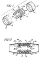
- Figure 1 is an exploded view in perspective showing the three pieces of the new anastomotic coupler of the present invention.
- Figure 2 is a cross-sectional view showing the new anastomotic coupler of the present invention joining a tubular vessel together.
- FIG. 1 there is shown a pair of cuffs 10 and 11 and a sleeve 12.
- the cuffs are identical and are generally cylindrical having a smooth innersurface and a smooth outer surface.
- an offset or shoulder portion 13 and 14 at one end of each cuff.
- This shoulder portion is formed by tapering the cuff from its outer surface to its inner surface at this end.
- the sleeve is also cylindrical in nature and the embodiment depicted has four legs 15 depending from each side of central portion 16 of the sleeve. Though in this embodiment the cylinder is discontinuous at each end to form four legs, the cylinder could form any number of legs or in fact be continuous or form only a single leg at each end.
- the central portion 16 of the sleeve has a plurality of circular grooves 17 or serrations about its periphery.
- the tubular member 30 to be joined is passed over the outside surface of a cuff and inverted down into the inside surface of the cuff.
- the sleeve is then passed down into the inside surface of the cuff so the ledge 18 on at least two of the legs engage the shoulder 13 of the cuff.
- the other end of the tubular member to be joined has the second cuff 11 inserted within its lumen and the tubular member inverted over the edge of the cuff.
- the cuff with the tubular member inverted over its end is placed on the opposite end of the sleeve 12 so that the ledge 19 on at least two of the legs at the opposite end of the sleeve engage the shoulder 14 of the cuff 11 to lock the device together and join the tubular members.
- the outside diameter of the cuffs should be the same size or slightly smaller than the inside diameter of the tubular member to be joined.
- the spacing between the cuffs should be slightly less than twice the thickness of the tubular member being joined so that as is seen in Figure 2 slight compression is placed on the tissue in the area where they are abutted. This slight compression establishes hemostatis and aids in the joining and healing of the tissue.
- the new coupling devices of the present invention may be manufactured by any convenient technique such as machining or molding.
- the device may be made from a variety of materials which are known to be bio-compatible in surgical applications. Nylon, polypropylene, and polysulfonate are illustrative of polymeric materials which are readily shaped into the minature pieces of the coupling device.
- the device may also be fabricated of stainless steel or of biologically absorbable materials such as polylactide, polyglycolide, polydioxanone, copolymers of lactide and glycolide, etc., which are known to hydrolyze in tissue with eventual complete absorption by the body.
- the essential element of the invention is a three-piece coupling device for end-to-end anastomosis of tubular members.
Abstract
57 A three-piece anastomotic coupling device comprising a pair of cuffs and an interlocking sleeve. The sleeve fits within the cuff and the entire device fits within the lumen of the tubular member to be joined.
Description
- The present-invention relates to devices for end-to-end anastomosis of tubular organs and, more particularly, to an anastomotic coupling device for reconnecting the ends of severed gastro-intestinal tract in a manner to promote the healing thereof.
- End-to-end anastomosis of the gastric organs may be accon- plished by suturing, stapling, or mechanical coupling. Suturing is generally tedious to perform and requires great skill and experience on the part of the surgeon. Suturing is also susceptible to complications resulting from damage to the gastric wall, leakage, potential harboring of infection around the suture material, and the like.
- Stapling and mechanical coupling of gastro-intestional structures has been suggested to avoid the disadvantages of suturing and to provide a more reliable fastener and a relatively simple method of anastomosis. Various designs for mechanical coupling devices have been proposed as, for example, in U.S. Patent Nos. 2,453,056, 3,221,746, 3,254,650, 3,774,615, 3,974,835, and 4,214,586.
- The-ideal anastonotic coupling device should provide perfect adaptation of the tubular members without damage to the gastric wall. The device should provide for quick, sure placement with a minimal possibility for error on the part of the surgeon. It is preferred the device be simple and economical to produce. In many instances, it is desirable that the anastomotic device be completely internal of the gastric lumen. There are other instances where it is desirable that the anastomotic device be substantially contained outside the lumen.
- It is accordingly an object of the present invention to provide an anastomotic device particularly adapted to joining gastro-intestional organs. A further object of this invention is to provide a device for joining the ends of interrupted tubular organs of various sizes and functions including, for example, intestines, veins, arteries, lymphatic ducts, ova ducts, and the like. These and other objects of the present invention may be evident from the ensuing description and claims.
- The anastomotic coupling device of the present invention consists of three pieces: two tubular cuffs and one locking sleeve. Preferred cuffs consist of a cylinder having an axial bore therein with smooth inner and outer surfaces. It is preferred one end of the cuffs have a shoulder which is used to abut a portion of the sleeve and lock the device in its final configuration in use. The cuffs are sized to fit within the lumen of a tubular member; that is, the tubular member to be joined. The tubular member is inverted over the end of the cuff opposite the end having the shoulder. The sleeve is cylindrical in configuration and has an axial bore therethrough and is sized to fit within the axial bore of the cuffs. The sleeve has means disposed at each end of the sleeve to lock with the cuff in the final device configuration such as an undercut ledge that engages the shoulder at one end of the cuff. In preferred embodiments, the outer surface of the cylindrical member is serrated or has circular grooves on it to aid in holding the tubular member in place.
- In use, one end of the tubular member to be joined is passed over the outer surface of a cuff and the tubular member is inverted so that the end fits inside the cuff. The cuff is then placed on one side of the sleeve so that the shoulder abuts against a ledge at the end of the sleeve. The other portion of the tubular member to be joined is placed over the second cuff and inverted so that the end of the tubular member fits inside the cuff. The second cuff with the tubular member inverted thereover is then sliped on the other end of the sleeve and locked in place by an appropriate undercut ledge so that the tubular members abut each other and are locked in place.
- The inside diameter of the cuffs is greater than the outside diameter of the sleeve by a sufficient amount to accommodate the wall thickness of the inverted tubular member. The diameters are preferably sized so that a small compressive force is inserted on the wall of the joined tubular member in the ,assernbled connector. As previously mentioned, in the preferred embodiments, the outer wall of the sleeve may contain serrations or otherwise be abraded to aid in holding the tubular member in place. The length of the sleeve and the pair of cuffs are such that when assembled the ends of the cuffs which face each other are spaced apart by a distance slightly less than twice the wall thickness of the tubular member being joined. In this manner the surfaces of the inverted ends of the tubular members are brought into contact under light compression which is effectfve to prevent leakage and is also desirable to promote healing of the joined tissue.
- Figure 1 is an exploded view in perspective showing the three pieces of the new anastomotic coupler of the present invention; and
- Figure 2 is a cross-sectional view showing the new anastomotic coupler of the present invention joining a tubular vessel together.
- In Figure 1 there is shown a pair of cuffs 10 and 11 and a
sleeve 12. The cuffs are identical and are generally cylindrical having a smooth innersurface and a smooth outer surface. In the embodiment depicted there is an offset orshoulder portion legs 15 depending from each side ofcentral portion 16 of the sleeve. Though in this embodiment the cylinder is discontinuous at each end to form four legs, the cylinder could form any number of legs or in fact be continuous or form only a single leg at each end. Thecentral portion 16 of the sleeve has a plurality ofcircular grooves 17 or serrations about its periphery. As can be seen more clearly in Figure 2, thetubular member 30 to be joined is passed over the outside surface of a cuff and inverted down into the inside surface of the cuff. The sleeve is then passed down into the inside surface of the cuff so theledge 18 on at least two of the legs engage theshoulder 13 of the cuff. The other end of the tubular member to be joined has the second cuff 11 inserted within its lumen and the tubular member inverted over the edge of the cuff. The cuff with the tubular member inverted over its end is placed on the opposite end of thesleeve 12 so that theledge 19 on at least two of the legs at the opposite end of the sleeve engage theshoulder 14 of the cuff 11 to lock the device together and join the tubular members. - The outside diameter of the cuffs should be the same size or slightly smaller than the inside diameter of the tubular member to be joined. The spacing between the cuffs should be slightly less than twice the thickness of the tubular member being joined so that as is seen in Figure 2 slight compression is placed on the tissue in the area where they are abutted. This slight compression establishes hemostatis and aids in the joining and healing of the tissue.
- The new coupling devices of the present invention may be manufactured by any convenient technique such as machining or molding. The device may be made from a variety of materials which are known to be bio-compatible in surgical applications. Nylon, polypropylene, and polysulfonate are illustrative of polymeric materials which are readily shaped into the minature pieces of the coupling device. The device may also be fabricated of stainless steel or of biologically absorbable materials such as polylactide, polyglycolide, polydioxanone, copolymers of lactide and glycolide, etc., which are known to hydrolyze in tissue with eventual complete absorption by the body.
- The preceding description has been largely directed to a preferred embodiment of the present invention and many variations thereof will be apparent to those skilled in the art. The essential element of the invention is a three-piece coupling device for end-to-end anastomosis of tubular members.
Claims (10)
1. A three-piece anastomotic coupling device for end-to-end anastomosis of tubular members, said device comprising:
two cuffs and a sleeve, each of said cuffs comprising a cylinder having an axial bore therethrough, said cuff being sized to fit within the lunen of a tubular member with the end of said tubular member inverted over one end of said cuff, said sleeve comprising a cylinder having an axial bore therethrough, said cylinder being sized to fit inside the axial bores of said cuffs with the inverted tubular members in abutting contact outside the cylinder and means for locking said cuffs and sleeve to maintain the inverted ends of the tubular members in contact.
2. A device according to Claim 1 wherein the interlocking means comprises a shoulder on each cuff engaging'ledges on opposite ends of the sleeve.
3. A device according to claim 1 or claim 2 wherein the sleeve comprises a cylinder having a central portion and a plurality of legs extending from each end of said central portion.
4. A device accordng to Claim 3 wherein at least two of the legs at each end of the central portion of the sleeve contain undercut ledges, said ledges engaging the ends of the cuffs opposite the ends on which the tubular member is inverted.
5. A device according to any one of claims 1 to 4 wherein the outer surface of the sleeve includes serrations to aid in gripping the tubular member to be joined.
6. A device according to any one of claims 1 to 5 wherein the inside diameter of the cuff is slightly larger than the outside diameter of the sleeve by a distance sufficient to accommodate . the wall thickness of the inverted tubular member.
7. A device according to any one of claims 1 to 6 wherein the ends of the cuffs facing each other in the assembled device are spaced apart by a distance sufficient to accommodate the combined wall thickness of the inverted tubular members.
8. A device according to any one of claims 1 to 7 fabricated from a bio-compatible polymeric material.
9. A device according to Claim 6 wherein said material is absorbable in a biological system.
10. A three-piece anastomotic coupling device for end-to-end anastomosis of tubular members, said device comprising:
two cuffs and a sleeve, each of said cuffs comprising a cylinder having an axial bore therethrough, said cuff being sized to fit within the lumen of the tubular member, the inner and outer surfaces of the cuffs being smooth, one end of each cuff being tapered towards its inner surface to form a shoulder at said end, said sleeve comprising a generally cylindrical center portion having an axial bore therethrough, a plurality of legs extending axially from each side of said central portion of said sleeve terminating in a radially outward extending ledge adapted to engage the shoulder of a cuff, said sleeve being sized to fit inside the axial bores of said cuffs, whereby when a tubular member to be joined is inverted over the end of one cuff opposite the tapered end and the other tubular member to be joined is inverted over the end of the other cuff opposite its tapered end and that sleeve positioned within the cuffs with the tubular members abutting one another and with the radially outwardly extending ledges on opposite legs of the sleeve engaging the shoulders on said cuffs, the tubular members are joined.
Applications Claiming Priority (2)
| Application Number | Priority Date | Filing Date | Title |
|---|---|---|---|
| US47630383A | 1983-03-17 | 1983-03-17 | |
| US476303 | 1983-03-17 |
Publications (2)
| Publication Number | Publication Date |
|---|---|
| EP0119848A2 true EP0119848A2 (en) | 1984-09-26 |
| EP0119848A3 EP0119848A3 (en) | 1986-02-26 |
Family
ID=23891313
Family Applications (1)
| Application Number | Title | Priority Date | Filing Date |
|---|---|---|---|
| EP84301797A Withdrawn EP0119848A3 (en) | 1983-03-17 | 1984-03-16 | Anastomotic coupling device |
Country Status (4)
| Country | Link |
|---|---|
| EP (1) | EP0119848A3 (en) |
| JP (1) | JPS59177039A (en) |
| AR (1) | AR230938A1 (en) |
| CA (1) | CA1243246A (en) |
Cited By (11)
| Publication number | Priority date | Publication date | Assignee | Title |
|---|---|---|---|---|
| EP0199074A1 (en) * | 1985-03-25 | 1986-10-29 | American Cyanamid Company | Process for manufacturing an annealed prosthetic device |
| US4625727A (en) * | 1985-01-24 | 1986-12-02 | Leiboff Arnold R | Anastomosis device with excisable frame |
| EP0326757A1 (en) * | 1988-02-05 | 1989-08-09 | Tatsuo Fujitsuka | Apparatus for anastomosing digestive tract |
| US4899744A (en) * | 1988-12-15 | 1990-02-13 | Tatsuo Fujitsuka | Apparatus for anastomosing digestive tract |
| EP0362163A2 (en) * | 1988-09-28 | 1990-04-04 | Carlo Rebuffat | Compression device for the anastomosis of hollow organs |
| US5180392A (en) * | 1988-02-01 | 1993-01-19 | Einar Skeie | Anastomotic device |
| EP1802237A2 (en) * | 2004-10-18 | 2007-07-04 | Tyco Healthcare Group Lp | Compression anastomosis device and method |
| WO2007122223A1 (en) * | 2006-04-21 | 2007-11-01 | Carponovum Ab | A device and a method for anastomosis |
| EP1908419A1 (en) * | 2006-10-06 | 2008-04-09 | Ethicon Endo-Surgery, Inc. | A locking device for an anastomotic device |
| KR101397170B1 (en) * | 2006-04-21 | 2014-05-19 | 카포노붐 에이비 | A mounting tool |
| CN117064474A (en) * | 2023-10-17 | 2023-11-17 | 山东百多安医疗器械股份有限公司 | Degradable vascular anastomosis device |
Families Citing this family (3)
| Publication number | Priority date | Publication date | Assignee | Title |
|---|---|---|---|---|
| JPS62152446A (en) * | 1985-12-24 | 1987-07-07 | 株式会社日本メデイカル・サプライ | Instrument for blood anastomosis |
| JP4504599B2 (en) * | 2001-07-27 | 2010-07-14 | 治文 加藤 | Anastomosis aid |
| CN113143372A (en) * | 2021-05-20 | 2021-07-23 | 上海理工大学 | Degradable pressurized lumen tissue anastomosis stent |
Citations (3)
| Publication number | Priority date | Publication date | Assignee | Title |
|---|---|---|---|---|
| US3683926A (en) * | 1970-07-09 | 1972-08-15 | Dainippon Pharmaceutical Co | Tube for connecting blood vessels |
| US4214586A (en) * | 1978-11-30 | 1980-07-29 | Ethicon, Inc. | Anastomotic coupling device |
| EP0070923A2 (en) * | 1981-07-27 | 1983-02-09 | American Cyanamid Company | Anastomotic device and method |
Family Cites Families (3)
| Publication number | Priority date | Publication date | Assignee | Title |
|---|---|---|---|---|
| US3974835A (en) * | 1972-11-30 | 1976-08-17 | Hardy Jr Thomas G | Anastomotic apparatus and method |
| JPS5642939A (en) * | 1979-09-17 | 1981-04-21 | Hitachi Ltd | Method for forming fluorescent surface on cathode-ray tube |
| ZA817222B (en) * | 1980-10-20 | 1982-09-29 | American Cyanamid Co | Anastomotic device and method |
-
1984
- 1984-03-12 CA CA000449357A patent/CA1243246A/en not_active Expired
- 1984-03-13 JP JP4663384A patent/JPS59177039A/en active Pending
- 1984-03-16 EP EP84301797A patent/EP0119848A3/en not_active Withdrawn
- 1984-03-17 AR AR29602484A patent/AR230938A1/en active
Patent Citations (3)
| Publication number | Priority date | Publication date | Assignee | Title |
|---|---|---|---|---|
| US3683926A (en) * | 1970-07-09 | 1972-08-15 | Dainippon Pharmaceutical Co | Tube for connecting blood vessels |
| US4214586A (en) * | 1978-11-30 | 1980-07-29 | Ethicon, Inc. | Anastomotic coupling device |
| EP0070923A2 (en) * | 1981-07-27 | 1983-02-09 | American Cyanamid Company | Anastomotic device and method |
Cited By (23)
| Publication number | Priority date | Publication date | Assignee | Title |
|---|---|---|---|---|
| US4625727A (en) * | 1985-01-24 | 1986-12-02 | Leiboff Arnold R | Anastomosis device with excisable frame |
| EP0199074A1 (en) * | 1985-03-25 | 1986-10-29 | American Cyanamid Company | Process for manufacturing an annealed prosthetic device |
| US5180392A (en) * | 1988-02-01 | 1993-01-19 | Einar Skeie | Anastomotic device |
| EP0326757A1 (en) * | 1988-02-05 | 1989-08-09 | Tatsuo Fujitsuka | Apparatus for anastomosing digestive tract |
| EP0362163A2 (en) * | 1988-09-28 | 1990-04-04 | Carlo Rebuffat | Compression device for the anastomosis of hollow organs |
| EP0362163A3 (en) * | 1988-09-28 | 1991-07-17 | Carlo Rebuffat | Compression device for the anastomosis of hollow organs |
| US4899744A (en) * | 1988-12-15 | 1990-02-13 | Tatsuo Fujitsuka | Apparatus for anastomosing digestive tract |
| AU2005296053B2 (en) * | 2004-10-18 | 2011-03-10 | Covidien Lp | Compression anastomosis device and method |
| EP1802237A2 (en) * | 2004-10-18 | 2007-07-04 | Tyco Healthcare Group Lp | Compression anastomosis device and method |
| US9023068B2 (en) | 2004-10-18 | 2015-05-05 | Covidien Lp | Compression anastomosis device and method |
| US8109948B2 (en) | 2004-10-18 | 2012-02-07 | Tyco Healthcare Group Lp | Compression anastomosis device and method |
| EP1802237A4 (en) * | 2004-10-18 | 2010-06-30 | Tyco Healthcare | Compression anastomosis device and method |
| US8512361B2 (en) | 2006-04-21 | 2013-08-20 | Carponovum Ab | Device and a method for anastomosis |
| CN101426430B (en) * | 2006-04-21 | 2011-11-02 | 卡波诺凡公司 | Method for a device for anastomosis |
| KR101351492B1 (en) * | 2006-04-21 | 2014-01-14 | 카포노붐 에이비 | A device for anastomosis |
| KR101397170B1 (en) * | 2006-04-21 | 2014-05-19 | 카포노붐 에이비 | A mounting tool |
| WO2007122223A1 (en) * | 2006-04-21 | 2007-11-01 | Carponovum Ab | A device and a method for anastomosis |
| US9155539B2 (en) | 2006-04-21 | 2015-10-13 | Carponovum Ab | Mounting tool and a method for a device for anastomosis |
| NO343928B1 (en) * | 2006-04-21 | 2019-07-08 | Carponovum Ab | Device and method of anastomosis |
| WO2008040577A1 (en) * | 2006-10-06 | 2008-04-10 | Ethicon Endo-Surgery, Inc. | A locking device for an anastomotic device |
| EP1908419A1 (en) * | 2006-10-06 | 2008-04-09 | Ethicon Endo-Surgery, Inc. | A locking device for an anastomotic device |
| CN117064474A (en) * | 2023-10-17 | 2023-11-17 | 山东百多安医疗器械股份有限公司 | Degradable vascular anastomosis device |
| CN117064474B (en) * | 2023-10-17 | 2024-01-05 | 山东百多安医疗器械股份有限公司 | Degradable vascular anastomosis device |
Also Published As
| Publication number | Publication date |
|---|---|
| JPS59177039A (en) | 1984-10-06 |
| AR230938A1 (en) | 1984-08-31 |
| EP0119848A3 (en) | 1986-02-26 |
| CA1243246A (en) | 1988-10-18 |
Similar Documents
| Publication | Publication Date | Title |
|---|---|---|
| CA1135456A (en) | Anastomotic coupling device | |
| US4534350A (en) | Two-piece tissue fastener with compressible leg staple and retaining receiver | |
| US8109948B2 (en) | Compression anastomosis device and method | |
| EP0119848A2 (en) | Anastomotic coupling device | |
| EP0070923B1 (en) | Anastomotic device and method | |
| US4532926A (en) | Two-piece tissue fastener with ratchet leg staple and sealable latching receiver | |
| US4873976A (en) | Surgical fasteners and method | |
| US4693248A (en) | Two-piece tissue fastener with deformable retaining receiver | |
| US4532927A (en) | Two-piece tissue fastener with non-reentry bent leg staple and retaining receiver | |
| US4552148A (en) | Anastomotic device | |
| US4766898A (en) | Anastomotic device | |
| US4724839A (en) | Surgical fastening systems made from polymeric materials | |
| US4693249A (en) | Anastomosis device and method | |
| US5346501A (en) | Laparoscopic absorbable anastomosic fastener and means for applying | |
| CN1023374C (en) | Anastomosis device | |
| JPH041626B2 (en) | ||
| EP0326757B1 (en) | Apparatus for anastomosing digestive tract | |
| EP0548521A1 (en) | Anastomotic device |
Legal Events
| Date | Code | Title | Description |
|---|---|---|---|
| PUAI | Public reference made under article 153(3) epc to a published international application that has entered the european phase |
Free format text: ORIGINAL CODE: 0009012 |
|
| AK | Designated contracting states |
Designated state(s): DE GB |
|
| PUAL | Search report despatched |
Free format text: ORIGINAL CODE: 0009013 |
|
| AK | Designated contracting states |
Designated state(s): DE GB |
|
| STAA | Information on the status of an ep patent application or granted ep patent |
Free format text: STATUS: THE APPLICATION IS DEEMED TO BE WITHDRAWN |
|
| 18D | Application deemed to be withdrawn |
Effective date: 19870129 |
|
| RIN1 | Information on inventor provided before grant (corrected) |
Inventor name: MERICLE, ROBERT WILLIAM |