EP0119814A2 - Stacking apparatus for paper sheets - Google Patents
Stacking apparatus for paper sheets Download PDFInfo
- Publication number
- EP0119814A2 EP0119814A2 EP84301674A EP84301674A EP0119814A2 EP 0119814 A2 EP0119814 A2 EP 0119814A2 EP 84301674 A EP84301674 A EP 84301674A EP 84301674 A EP84301674 A EP 84301674A EP 0119814 A2 EP0119814 A2 EP 0119814A2
- Authority
- EP
- European Patent Office
- Prior art keywords
- paper sheets
- blade
- paper sheet
- arm
- stacking
- Prior art date
- Legal status (The legal status is an assumption and is not a legal conclusion. Google has not performed a legal analysis and makes no representation as to the accuracy of the status listed.)
- Granted
Links
- 230000007246 mechanism Effects 0.000 claims abstract description 18
- 230000002093 peripheral effect Effects 0.000 claims description 16
- 230000001133 acceleration Effects 0.000 claims description 3
- 238000000034 method Methods 0.000 description 6
- 230000003287 optical effect Effects 0.000 description 6
- 230000004044 response Effects 0.000 description 5
- 238000003780 insertion Methods 0.000 description 3
- 230000037431 insertion Effects 0.000 description 3
- 238000010276 construction Methods 0.000 description 2
- 230000004048 modification Effects 0.000 description 2
- 238000012986 modification Methods 0.000 description 2
- 238000010009 beating Methods 0.000 description 1
- 230000000903 blocking effect Effects 0.000 description 1
- 230000003247 decreasing effect Effects 0.000 description 1
- 238000010586 diagram Methods 0.000 description 1
- 238000006073 displacement reaction Methods 0.000 description 1
- 230000000694 effects Effects 0.000 description 1
- 230000007257 malfunction Effects 0.000 description 1
- 230000008569 process Effects 0.000 description 1
- 238000004064 recycling Methods 0.000 description 1
- 125000006850 spacer group Chemical group 0.000 description 1
- 238000011144 upstream manufacturing Methods 0.000 description 1
Images


Classifications
-
- B—PERFORMING OPERATIONS; TRANSPORTING
- B65—CONVEYING; PACKING; STORING; HANDLING THIN OR FILAMENTARY MATERIAL
- B65H—HANDLING THIN OR FILAMENTARY MATERIAL, e.g. SHEETS, WEBS, CABLES
- B65H29/00—Delivering or advancing articles from machines; Advancing articles to or into piles
- B65H29/38—Delivering or advancing articles from machines; Advancing articles to or into piles by movable piling or advancing arms, frames, plates, or like members with which the articles are maintained in face contact
- B65H29/40—Members rotated about an axis perpendicular to direction of article movement, e.g. star-wheels formed by S-shaped members
-
- B—PERFORMING OPERATIONS; TRANSPORTING
- B65—CONVEYING; PACKING; STORING; HANDLING THIN OR FILAMENTARY MATERIAL
- B65H—HANDLING THIN OR FILAMENTARY MATERIAL, e.g. SHEETS, WEBS, CABLES
- B65H31/00—Pile receivers
- B65H31/32—Auxiliary devices for receiving articles during removal of a completed pile
-
- B—PERFORMING OPERATIONS; TRANSPORTING
- B65—CONVEYING; PACKING; STORING; HANDLING THIN OR FILAMENTARY MATERIAL
- B65H—HANDLING THIN OR FILAMENTARY MATERIAL, e.g. SHEETS, WEBS, CABLES
- B65H2301/00—Handling processes for sheets or webs
- B65H2301/40—Type of handling process
- B65H2301/42—Piling, depiling, handling piles
- B65H2301/421—Forming a pile
- B65H2301/4212—Forming a pile of articles substantially horizontal
-
- B—PERFORMING OPERATIONS; TRANSPORTING
- B65—CONVEYING; PACKING; STORING; HANDLING THIN OR FILAMENTARY MATERIAL
- B65H—HANDLING THIN OR FILAMENTARY MATERIAL, e.g. SHEETS, WEBS, CABLES
- B65H2301/00—Handling processes for sheets or webs
- B65H2301/40—Type of handling process
- B65H2301/42—Piling, depiling, handling piles
- B65H2301/426—Forming batches
-
- B—PERFORMING OPERATIONS; TRANSPORTING
- B65—CONVEYING; PACKING; STORING; HANDLING THIN OR FILAMENTARY MATERIAL
- B65H—HANDLING THIN OR FILAMENTARY MATERIAL, e.g. SHEETS, WEBS, CABLES
- B65H2701/00—Handled material; Storage means
- B65H2701/10—Handled articles or webs
- B65H2701/19—Specific article or web
- B65H2701/1912—Banknotes, bills and cheques or the like
Definitions
- the present invention relates to a stacking apparatus for paper sheets having: blade wheel means which is rotated such that an axis of rotation thereof is horizontally aligned and which has elongated wheel blades each extending in a direction opposite to a rotational direction of the blade wheel means from a center portion about the axis of rotation to a peripheral surface of the blade wheel means; feeding means for feeding paper sheets one by one in each of elongated spaces formed between every two adjacent blades of the elongated blades, at a speed exceeding a peripheral velocity of the blade wheel means; and stacking means for stacking the paper sheets sorted by and sequentially discharged in groups of predetermined number, from the blade wheel means.
- Paper sheets such as bank notes, data cards, or printed matter are automatically handled. These documents have been increasing year by year. A strong demand has arisen for a machine handling these paper sheets at high speed.
- a typical example is a bundling operation for recycling a predetermined number of currency notes.
- Manual counting and bundling of currency notes is time-consuming and cumbersome.
- currency notes are automatically grouped in units of a predetermined number and bundled by a currency note arranger or the like.
- the automatic currency note arranger of this type it is assumed ideal that the currency notes transported at high speed are continously stacked in units of predetermined numbers without interruption.
- a stacking means called a beat (direction changing) method in which a paper sheet, discharged from the transporting end and floating in air, is beaten towards a perpendicular direction and dropped onto a stacking unit.
- direction changing means of this type has a limited response speed. More specifically, when a direction changing member vibrates with a given magnitude at high speed, the vibration cycle is increased and with it the inertia force. As a result, operation of the direction changing means becomes unstable.
- the force acting on the mechanism of the direction changing means is increased, the means must have a large construction as a whole which results in malfunctions and high cost.
- the force beating the paper sheet is increased, so that the sheet tends to be torn. Therefore, this direction changing means is not suitable for high-speed operation.
- a blade wheel is used to overcome the above-mentioned stacking means.
- the blade wheel has wheel blades, each extending from the center portion to the peripheral surface of the blade wheel.
- the wheel blades extend in the opposite direction to the rotational direction of the wheel.
- the paper sheets are inserted in the narrow spaces formed between the blades of the wheel and are stacked.
- the time interval t (min.) is given by observing the paper sheets at a given position along a transporting passage, from: where N is the number of paper sheets fed per minute into the wheel.
- n (1/m)/(1/N) ⁇ N/m
- the rotational speed n of the wheel is obtained by dividing the number of fed sheets by the number of narrow spaces.
- the rotational speed of the wheel is very low. Assume that high-speed transportion is performed at the speed of 1800 sheets/min., and that the wheel has 18 narrow spaces.
- a stacking apparatus for paper sheets wherein the blade wheel stacking means is combined with means for sorting paper sheets into units of a predetermined number.
- a separator has an arm having substantially the same axis of rotation as that of the wheel and extending from the center portion around the axis of rotation of the wheel to the outside of the peripheral surface of the wheel, along the side of the wheel.
- the separator also has a receiving portion integrally formed at the distal end of the arm. The separator is pivoted as needed to abut the arm against the paper sheet inserted between the blades, so the paper sheet is removed from the space formed between the corresponding blades.
- the paper sheet is temporarily held by the receiving portion. During this period, the sheets, previously discharged from a stationary stopper and stacked on the stacking means, are removed to a predetermined portion. Thereafter, the sheets stacked on the separator are transferred to the stacking means.
- the arm of the separator When temporarily receiving paper sheets outside the predetermined number, the arm of the separator is used as a stopper to remove these subsequent paper sheets which are sequentially held by the receiving portion.
- the arm is located within the width, along the axis of rotation of the wheel, of the paper sheet insertion position in the space of the blade wheel. For this reason, when the separator is located between the sheet feeding position and the sorting start position (receiving start position), the sheet receiving depth of the space of the wheel becomes shallow due to the presence of the arm.
- the present invention has been made in consideration of the above situation and has for its object to provide a stacking apparatus for paper sheets which does not impair the high-speed handling capacity inherent in a blade wheel stacking method and which is capable of sorting paper sheets into units of a predetermined number for stacking.
- a stacking apparatus for paper sheets comprising: a stationary stop for stopping rotation of the paper sheet corresponding one of the elongated spaces at a position where the paper sheet, inserted in a corresponding one of the elongated spaces, is rotated through at a predetermined angle of rotation of the blade wheel means and for removing the paper sheet from the corresponding space to drop the paper sheet; an arm which has the same axis of rotation as that of the blade wheel means and passing by the side of paper sheets, which is rotatably supported while the arm is not brought into contact with the paper sheet inserted in the elongated spaces, and which extends along a side surface of said blade wheel means; a receiving portion, supported by the arm and located outside a peripheral edge of the blade wheel means, so as to temporarily receive the paper sheet which naturally drops; and controlling means for controlling and driving the arm.
- the paper sheet which is transported in the blade wheel means will not contact the arm irrespective of the position of the arm. Therefore, the paper sheet transported in the space of the blade wheel means can be completely and smoothly inserted in the space at high speed. Unlike in the conventional stacking apparatus, the distance between the adjacent paper sheets to be transported in the blade wheel can be shortened. For this reason, the paper sheets can be grouped and stacked in units of a predetermined number while high-speed handling of the blade wheel is maximized.
- Fig. 1 is a partially cutaway side view showing the main part of a stacking apparatus for paper sheets according to an embodiment of the present invention
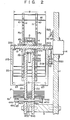
- Fig. 2 is a cross-sectional view of the apparatus along the line II - II of Fig. 1;
- reference numeral 1 denotes a vertical base plate.
- a pair of support plates 2a and 2b are disposed on one side surface of the base plate 1.
- the support plates 2a and 2b are spaced apart from each other and are parallel to the side surface of the base plate 1.
- the lower ends of the support plates 2a and 2b are mounted on the base plate 1 through a support plate 3.
- the support plates 2a and 2b have vertical surfaces 2c at the lower portions of the left end walls thereof (Fig. 1). These vertical surfaces 2c serve as stoppers for stopping the movement of the paper sheet (to be described later) and will be referred to as stoppers 2c.
- the outer rings of bearings 3a and 3b are mounted coaxially on the support plates 2a and 2b in a direction perpendicular to the side surface of the base plate 1.
- a hollow pulley 4 is rotatably mounted on the inner rings of the bearings 3a and 3b.
- An endless belt 5 is looped around the outer surface of the pulley 4 at one side and is coupled to a driving source (not shown) at the other side, so that the pulley is driven at a predetermined speed.
- Blade wheel means i.e., a pair of blade wheels
- the distance between blade wheels 7a and 7b is shorter than a width W of a paper sheet 16.
- Holes 9 are respectively formed at the centers of the blade wheels 7a and 7b and have substantially the same inner diameter as that of the pulley 4.
- Elongated blades 10 extend in a direction opposite to the rotational direction of the wheels 7a and 7b and from the center portion to the peripheral portion of the wheels 7a and 7b, as if the blades 10 draw an involute curve, as shown in Fig. 1.
- Each elongated space 11 is formed between every two adjacent blades 10.
- the blade wheels 7a and 7b are mounted on the pulley 4 such that the spaces 11 of the blade wheels 7a and 7b are aligned with each other along the direction of the shaft 13.
- the outer rings of bearings 12a and 12b are coaxially mounted at two ends of the inner surface of the pulley 4.
- the shaft 13 is rotatably mounted on the inner rings of the bearings 12a and 12b.
- One end of the shaft 13 extends outside the blade wheel 7b without being brought into contact with the hole 9 therein.
- the other end of the shaft 13 also extends outside the blade wheel 7a without being brought into contact with the hole 9 therein and is coupled to the rotating shaft of a pulse motor 14 mounted on the base plate 1.
- a pair of separators 21a and 21b are mounted on the shaft 13 to sandwich the blade wheels 7a and 7b therebetween.
- the separators 21a and 21b have arms 22 and receiving portions or receiving hands 23.
- the arms 22 are parallel to the outer side surfaces of the blade wheels 7a and 7b and extend outside the peripheral edges thereof.
- the receiving hands 23 extends from the distal ends of the corresponding arms 22 parallel to the shaft 13, towards the blade wheels 7a and 7b, and then towards imaginary arcs having as their center the axis of the shaft 13, protruding by a length more than half that of the paper sheet 16 along the blades 10 of the blade wheels 7a and 7b, respectively.
- the separators 21a and 21b are so aligned that end faces 24 of the arms 22 are disposed on the same plane.
- Proximal ends 22a of the arms 22 are mounted on the shaft 13 such that a distance S (Fig. 3) between the arms 22 is longer than the width W of the paper sheet 16.
- the receiving portions i.e., the receiving hands 23
- the receiving hands 23 are integrally formed with the arms 22.
- the receiving hands 23 are located outside imaginary circles drawn by the blade wheels 7a and 7b.
- a transporting or conveyer belt mechanism 31 (Fig. 1) is disposed in the upper portion between the blade wheels 7a and 7b to transport the paper sheet 16 into the corresponding spaces 11 of the blade wheels 7a and 7b.
- the belt mechanism 31, as the feeding means comprises: a pulley 32 disposed between the blade wheels 7a and 7b such that the axis of rotation thereof is parallel to that of the shaft 13; two lower belts 34 looped around the pulley 32, parallel to each other at two different positions along a direction perpendicular to the drawing surface (Fig.
- the pulley 32 and 37 are supported on the base plate 1 through support members (not shown).
- the upper and lower belts 36 and 34 are driven at an identical speed which is higher than the peripheral velocity of the blade wheels 7a and 7b.
- a stacking unit 41 as the stacking means, is disposed below the blade wheels 7a and 7b.
- the stacking unit 41 comprises: bearings 42a and 42b whose outer rings are mounted in the lower portions of the support plates 2a and 2b parallel to the shaft 13; a shaft 43 mounted in the inner rings of the bearings 42a and 42b; pulleys 44a, 44b and 44c fixed on the surface of the shaft 43 and spaced apart from each other; a group of belts, i.e., belts 45a, 45b and 45c (only the belt 45c is shown to extend to the left, as illustrated in Fig. 1) looped around the pulleys 44a, 44b and 44c respectively; and a drive control unit for driving these belts.
- a bar 51 is fixed on the shaft 13 at a position near the pulse motor 14 and detects the positions of the separators 21a and 21b.
- the bar 51 has substantially an equal width (along the peripheral direction) to that of the arm 22 of each of the separators 21a and 21b.
- the bar 51 is fixed to the shaft 13 such that the bar 51 extends in the same direction as that of the arm 22.
- separator detectors 52a and 52b are fixed on a side surface of the base plate 1 to detect the rotational position of the bar 51 while the bar 51 is not brought into contact with the separator detectors 52a and 52b. Dotted circles B and C in each of Figs.
- each of the separator detectors 52a and 52b comprises a photocoupler consisting of a light-emitting element 53 and a light-receiving element 54, which are linearly aligned opposing each other, as shown in Fig. 4.
- Each of the separator detectors 52a and 52b generates a low level signal when the bar 51 is inserted between the corresponding elements 53 and 54 to shield light from the light-receiving element 54. Otherwise, each detector generates a high level signal.
- the separator detector 52a generates a low level signal when the bar 51 (i.e., the arm 22 of the separators 21b (21a)) is located at a position indicated by the dotted circle B in Fig. 1.
- the separator detector 52b generates a low level signal when the arm 22 of the separator 21b (21a) is located at a position indicated by the dotted circle C in Fig. 1.
- the positions B and C will be described in detail later.
- a recess 55 (Fig. 2) is formed in the surface of the support plate 2a which opposes the inner surface of the blade wheel 7a.
- a pulse generator 56 is arranged in the recess 55 to generate pulses in synchronism with the rotation of the blade wheels 7a and 7b.
- the pulse generator 56 comprises a photocoupler consisting of a light-emitting element 57 for emitting light towards the inner surface of the blade wheel 7a at a predetermined angle, and a light-receiving element 58 for receiving light reflected by the inner surface of the blade wheel 7a.
- a plurality of apertures 59 is formed in a circular shape on the portion of the blade wheel 7a which receives the reflected light.
- the apertures 59 are formed at positions falling on lines connecting a center 60 of the blade wheel 7a and tips 61 of the blades 10.
- the pulse generator 56 generates an output signal when incident light on the light receiving element 58 transmited from the light-emitting element 57 through one of the apertures 59 is cut off.
- a paper number detector 63 is disposed in the vicinity of the feeding port of the paper sheet 16, in the overlapping portion between the upper and lower belts 36 and 34 of the belt mechanism 31, to count the number of paper sheets 16 conveyed while being clamped between the belts 34 and 36, and to generate an output pulse when a count thereof reaches a predetermined number plus one.
- the detector 63 comprises a light-emitting element 64 and a light-receiving element 65, which are disposed below and above the overlapping portion of the belts 34 and 36, between two pairs of belts 34 and 36, as shown in Fig. 1.
- a paper flow detector 66 (Fig. 1) is arranged in the part of the overlapping portion, which is located upstream of the detector 63, and detects the flow of a paper sheet 16 clamped between the belts 34 and 36.
- the detector 66 comprises a photocoupler consisting of a light-emitting element 67 and a light-receiving element 68, which are arranged below and above the belts 34 and 36 respectively, between two pairs of belts 34 and 36.
- the detector 66 generates an output pulse when the paper sheet 16 has passed through it.
- a stacking detector 69 (Fig. 1) is disposed in the vicinity of the stacking unit 41.
- the detector 69 is arranged such that a light-emitting element 70 and a light-receiving element 71 are placed on an oblique line on a plane perpendicular to the shaft 13, as shown in Fig. 1.
- the light-receiving element 71 receives light from the light-emitting element 70, it generates an output signal.
- Outputs El and E2 from the separator detectors 52a and 52b, an output F from the pulse generator 56, an output J from the detector 63, an output K from the detector 66, and an output M from the detector 69 are supplied to a control unit 81 as the controlling means for driving the pulse motor 14 and the belts 45a, 45b and 45c of the stacking unit 41.
- the control unit 81 has a detailed configuration, as shown in Fig. 7.
- the control unit 81 has six input terminals 82, 83, 84, 85, 86 and 87.
- the output El from the detector 52a is supplied to the input terminal 82 and to one input terminal of an AND gate 88.
- the output J from the detector 63 is supplied to the input terminal 83 and to one input terminal of an AND gate 91 through a delay circuit 89 having a predetermined delay time and a one-shot multivibrator 90.
- the output F from the pulse generator 56 is supplied to the input terminal 84 and to the other input terminal of the AND gate 91.
- the output M from the detector 69 is supplied to the input terminal 85 and to the second input terminal of an AND gate 93 through a delay circuit 92.
- the output K from the detector 66 is supplied to the third input terminal of the AND gate 93 through the input terminal 86.
- the output El is supplied to the first input terminal of the AND gate 93 through an inverter 94.
- the output E2 from the detector 52b is supplied to the input terminal 87 and to one input terminal of an AND gate 95.
- An output from the AND gate 91 is supplied to the other input terminal of the AND gate 88 through a one-shot multivibrator 96.
- An output from the AND gate 93 is supplied to the other input terminal of the AND gate 95 through a one-shot multivibrator 97.
- a pulse generator 98 (to be described in detail later) is provided for generating a pulse having a period to be described later.
- the output terminal of the pulse generator 98 is connected to a common node of the collectors of npn transistors 99 and 100.
- the commonly connected emitters of the transistors 99 and 100 are connected to the collectors of npn transistors 101 and 102.
- An output from the AND gate 88 is commonly supplied to the bases of the transistors 99 and 102.
- An output from the AND gate 95 is commonly supplied to the bases of the transistors 100 and 101.
- An emitter output from the transistor 102 is supplied as a drive control signal to a drive circuit 103 for driving the pulse motor 14.
- An emitter output from the transistor 101 is supplied to a counter 104.
- An output from the counter 104 is supplied to the drive circuit 103 through a digital-to-analog converter 105 (to be referred to as a D/A converter hereinafter) and a voltage-to-frequency converter 106 (to be referred to as a V/f converter hereinafter).
- the counter 104 is reset in response to a differentiator circuit 107 for differentiating the trailing edge of the output E2.
- the electrical characteristics of the V/f converter 106 are preset in accordance with the position of the detector 66.
- An output from the inverter 94 is supplied to a differentiator circuit 109 through a delay circuit 108.
- the differentiator circuit 109 differentiates the leading edge of the output from the delay circuit 108.
- An output from the differentiator circuit 109 is supplied as a drive signal to a one-shot multivibrator 110.
- An output from the one-shot multivibrator 110 is supplied as a control signal to a drive circuit 111 for driving a motor 112 for moving the belts 45a, 45b and 45c of the stacking unit 41.
- the travel speed of the belt mechanism 31 and the feeding of the paper sheet 16 into the mechanism 31 must be preset such that a time interval is given to be 50 msec, during which the leading edge of a given paper sheet, transported by the belt mechanism 31, passes a given position and the leading edge of the next paper sheet reaches the given position.
- a time interval is 25 msec, during which the trailing edge of the given paper sheet passes the given position and the leading edge of the next paper sheet reaches the given position.
- the rotational speed of the blade wheels 7a and 7b is set as follows.
- each blade wheel has 12 elongated spaces 11, the angle a of rotation of the blade wheel, corresponding to one space, is 30 degrees. This angular displacement is performed for a time interval of 50 msec, so the rotational speed N of each of the blade wheels 7a and 7b is set to be 100 rpm. Therefore, a driving source (not shown) drives the blade wheels 7a and 7b at a speed of 100 rmp in the direction indicated by an arrow 120 in Fig. 1, and the belts 34 and 36 travel along the arrows 33 and 35 respectively, satisfying the above conditions.
- the separators 21a and 21b stop at given positions or standby position (i.e., the position of the separator 21b which is aligned with the separator detector 52b as indicated by the dotted circle C in Fig. 1) where the separators 21a and 21b pass the feeding port of the belt mechanism 31 in the rotational direction of the blade wheels 7a and 7b, as shown in Fig. 10.
- the distance S between the arms 22 of the separators 21a and 21b is preset to be longer than the width W of the paper sheet 16.
- the receiving hands 23 are located outside the peripheral edges of the blade wheels 7a and 7b.
- the separators 21a and 21b are not brought into contact with the paper sheet, which is fed from the feeding port of the belt mechanism 31 and which is ready for insertion into the corresponding space 11 of the blade wheels 7a and 7b. Therefore, the paper sheet 16 is inserted from its leading edge into the space 11 whether or not the separators 21a and 21b are present.
- the insertion speed of the paper sheet 16 into the space 11 is decreased since the space forms an arc shape, so that the paper sheet 16 is entirely inserted in the space 11.
- the paper sheet 16 is rotated with the rotation of the blade wheels 7a and 7b.
- the pulse generator 56 (Fig. 2) has the apertures 59 (Fig. 6) as previously described, so that the pulse generator 56 generates the output pulses F having a period of 50 ms. Similarly, the detector 66 generates the output pulses K having a period of 50 ms.
- the detector 63 When the detector 63 detects the trailing edge of a 101st sheet following the predetermined number of 100 sheets, while the paper sheets 16 are sequentially stacked, the detector 63 generates the output pulse J as shown in the Fig. 8.
- the 101st sheet is the first sheet included in the next stack of sheets.
- the output pulse J is supplied to one input terminal of the AND gate 91 through the delay circuit 89 and the one-shot multivibrator 90 in the control unit or control means 81.
- a delay time T1 of the delay circuit 89 is preset as follows. Assume in Fig. 10 that a paper sheet 16a, inserted in a space lla between blades 10a and 10b, is the 101st paper sheet.
- the delay time Tl is preset tq be a time interval between a moment at which the trailing edge of the 101st paper sheet crosses the optical path of the detector 63 (i.e., tl) and a moment at which the.tip 18 of the blade 10b, located immediately before the paper sheet 16a, is aligned with the central axis R of the arms 22 of the separators 21a and 21b.
- the pulse generator 56 When the tip 18 of the blade 10b is rotated to align with the central axis R (i.e., when the tip of the paper sheet 16a passes by the arms 22 of the separators 21a and 21b and is inserted deep into the space lla), the pulse generator 56 generates the output pulse F, as is apparent from the positional relationship between the apertures 59 shown in Fig. 6. This moment is given to be t2.
- the AND gate 91 is enabled in response to an output F2 at time t2, so that the one-shot multivibrator 96 is driven.
- the output El of the detector 52a is at high level.
- the AND gate 88 is enabled at time t2, so that the transistors 99 and 102 are turned on.
- the output pulse from the pulse generator 98 is supplied to control the drive circuit 103 through the transistors 99 and 102.
- the pulse motor 14 is rotated to turn the separators 21a and 21b counterclockwise as in Fig. 11.
- the pulse generator 98 is constructed to generate pulses of a period such that the rotational speed of the blade wheels 7a and 7b coincides with that of the pulse motor 14. Therefore, the separators 21a and 21b are rotated at the same angular velocity as that of the blade wheels 7a and 7b in an identical direction, while the central axis R of the arms 22 is aligned with the tip 18 of the blade 10b, as shown in Fig. 11.
- the 101st paper sheet is gradually removed from the space lla and completely discharged therefrom.
- the separators 21a and 21b are rotated in a state wherein the central axis R of the arms 22 is located at the side of the tip 18a of the blade 10b, so that the 101st paper sheet removed from the space lla cannot drop downward but is received by the hands 23 of the separators 21a and 21b.
- an output EI from the inverter 94 rises.
- the output E1 is supplied to the delay circuit 108 and the differentiator circuit 109 for differentiating the leading edge of the output from the delay circuit 108.
- the output from the differentiator circuit 109 is supplied as the control signal for the drive circuit 111 of the motor 112 through the one-shot multivibrator 110. For this reason, when a time interval T2 has elapsed to give time t3, the motor 112 is started with the result that the belts 45a, 45b and 45c travel for a time interval preset by the one-shot multivibrator 110 in the direction indicated by an arrow 121 (Fig. 13).
- the delay time T2 of the delay circuit 108 is preset to correspond to the time taken for the 100 paper sheets 16 to be completely cleared away. While the paper sheets stacked on the belts 45a, 45b and 45c are moved, the paper sheets 16 are sequentially stacked on the receiving hands 23.
- the output M from the detector 69 rises.
- the output M is supplied to the AND gate 93 through the delay circuit 92.
- the delay time T3 of the delay circuit 92 is preset to correspond to the time interval between time t4 when the output M rises and the time when the belts 45a, 45b and 45c stop. In this manner, when the output from the delay circuit 92 rises, the output El from the inverter 94 is at a high level.
- the detector 66 when a time interval has elapsed to give time t5, the detector 66 generates the output K, and the AND gate 93 is enabled. Therefore, the one-shot multivibrator 97 is driven. In this case, the output E2 from the detector 52b is set at high level, so that the AND gate 95 is enabled at time t5 to turn on the transistors 100 and 101. As a result, the output pulse from the pulse generator 98 is supplied to a control pulse system 120 through the transistors 100 and 101.
- the control pulse system 120 comprises the counter 104, the D/A converter 105 and the V/f converter 106, which are connected in series, and serves to move the separators from the lower position of Fig. 12 to the upper position of Fig.
- the counter 104 in the control pulse system or control circuit 120 counts the pulses from the pulse generator 98 and supplies a count signal to the D/A converter 105.
- the D/A converter 105 generates a voltage corresponding to the count signal.
- This voltage from the D/A converter 105 is applied to the V/f converter 106, which converts it into a pulse signal having a pulse recurrence frequency corresponding to the output of the D/A converter.
- This signal is supplied to the pulse motor 14 through the drive circuit 103. Therefore, when the counter 104 starts counting the pulses generated from the pulse generator 98, the pulse motor 14 is also started from the stop state at a speed corresponding to the elapsed time.
- the pulse motor 14 is started again from time t5, and the separators 21a and 21b are rotated in the same direction as that of the blade wheels 7a and 7b. Along with this rotation, the paper sheets 16 stacked on the receiving hands 23 of the separators 21a and 21b are transferred to the belts 45a, 45b and 45c, as shown in Fig. 14.
- the control pulse system 120 comprising the counter 104, the D/A converter 105 and the V/f converter 106, is operated as follows. Assume that a position where the optical axis of the photocoupler of the detector 66 crosses the belt mechanism 31 is given to be X, that a position where a track Z of the receiving hands 23 crosses the belt mechanism 31 when the separators 21a and 21b are rotated is defined to be Y, then a distance between the positions X and Y is constant. Since the travel speed of the belt mechanism 31 is predetermined, a time interval Tl, during which the trailing end of the paper sheet 16 passes both X and Y, is constant.
- the paper sheet which passes the position Y is not present during the given interval after the immediately preceding paper sheet passes through the position Y.
- This given time interval occures every 50 ms.
- the pulse motor 14 is started at time t5
- the rotational force is increased with a predetermined torque rate.
- the control pulse system is operated such that the receiving hands 23 of the separators 21a and 21b pass by the position Y at a speed which is several times that of the travel speed of the belt mechanism 31.
- Fig. 9 illustrates the relationship between the angular velocity and the loading torque of the pulse motor 14 when the separators 21a and 21b are moved from the state of Fig. 10 to the state of Fig. 12.
- a positive or negative torque acts on the separators 21a and 21b when the angular velocity changes.
- a relatively low torque acts on the separators 21a and 21b for overcomming a bearing frictional force.
- a relative high torque acts on the separators 21a and 21b against the inertia force thereof.
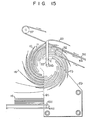
- the separators 21a and 21b are rotated as described above, the receiving hands 23 extend above the blade wheels 7a and 7b, as shown in Fig. 15, and the arms 22 reach at the side of the detector 52b, so that the bar 51 blocks the optical path of the photocoupler of the detector 52b at time t6.
- the output E2 from the detector 52b lowers.
- the AND gate 95 is closed to turn off the transistors 100 and 101.
- the counter 104 is reset in response to the output from the differentiator circuit 107.
- the motor 14 is stopped, and the separators 21a and 21b stop at a position i.e. standby position indicated in Figs. 10 and 15 are set in the standby mode. Thereafter, the above operation is repeated in response to the output J from the detector 63. Therefore, the paper sheets 16, fed one by one edgewise, can be sorted in units of 100 sheets, and the 100-sheet groups are fed in the subsequent unit, thereby providing efficient handling of the stacking apparatus having the sorting means.
- the arms 22 of the separators 21a and 21b are located at positions (i.e., outside the two ends of the paper sheet inserted in the spaces 11 of the blade wheels 7a and 7b) where the arms 22 will not be brought into contact with the paper sheets 16, so that the travel path of the paper sheet to be inserted in the space 11 will not be interfered with by the arms 22, irrespective of the positions of the separators 21a and 21b. Therefore, the feeding rate of the paper sheets is not limited due to the presence of the separators 21a and 21b.
- the paper sheets are continuously fed, grouped and discharged in the subsequent process.
- the present invention is not limited to the above embodiment.
- the separators 21a and 21b stop at the standby position of Fig. 10 or the receiving position of Fig. 12.
- the separators 21a and 21b may stop at an intermediate position (as illustrated in Fig. 14) between the standby position and the receiving position.
- the control circuit may be arranged such that the receiving hands 23 of the separators 21a and 21b pass through a space formed between the paper sheets 16 at a speed several times the travel speed of the belt mechanism 31. In this case, the loading torque of the pulse motor 14 is increased as compared with that in the above embodiment.
- the time interval between the time at which the separator 21a and 21b start and the time at which the separators 21a and 21b pass across the travel path of the sheets 16 is short, so that the determining timing of the movement of the receiving hands 23 across the travel path of the sheet 16 can be simplified.
- the moving speed of the separators 21a and 21b may become the same as that of the blade wheels 7a and 7b to rotate the separators 21a and 21b in the direction from the standby position toward the receiving position in the same manner as in the above embodiment.
- the separators 21a and 21b are rotated through 360 degrees.
- the separators 21a and 21b may be rotated through 180 degrees, or therewithin, and may be controlled with an axial movement control system. In this case, only one separator is arranged and a fork-like receiving hand is formed integrally at the distal end of the arm. As shown in Fig. 12, when the receiving hands receive the paper sheets having numbers larger than a predetermined number, the stacked paper sheets on the stacking unit 41 are discharged, and the paper sheets stacked on the receiving hands are transferred to a substacking unit (not shown) by utilizing an open space of the receiving hands 23. Thereafter, the separator is axially moved such that the receiving hand 23 is cleared away from the lower portion of the blade wheels 7a and 7b.
- the paper sheets stacked on the substacking unit are moved onto the main stacking unit, and the separator is rotated through a predetermined angle in the direction opposite to the rotational direction of the blade wheels.
- the separator is then moved in the direction opposite to the direction described above so as to face the receiving hand at the outer surfaces of the blade wheels.
- the separator is then rotated from the standby position to the receiving position in the same manner as in the above embodiment.
- a series of operations described above are then repeated.
- the blades of the blade wheels are formed in an involute curve.
- the shape of the blades is not limited to this curve but can be extended to a different known shape.
Abstract
Description
- The present invention relates to a stacking apparatus for paper sheets having: blade wheel means which is rotated such that an axis of rotation thereof is horizontally aligned and which has elongated wheel blades each extending in a direction opposite to a rotational direction of the blade wheel means from a center portion about the axis of rotation to a peripheral surface of the blade wheel means; feeding means for feeding paper sheets one by one in each of elongated spaces formed between every two adjacent blades of the elongated blades, at a speed exceeding a peripheral velocity of the blade wheel means; and stacking means for stacking the paper sheets sorted by and sequentially discharged in groups of predetermined number, from the blade wheel means.
- Paper sheets such as bank notes, data cards, or printed matter are automatically handled. These documents have been increasing year by year. A strong demand has arisen for a machine handling these paper sheets at high speed.
- A typical example is a bundling operation for recycling a predetermined number of currency notes. Manual counting and bundling of currency notes is time-consuming and cumbersome. In practice, currency notes are automatically grouped in units of a predetermined number and bundled by a currency note arranger or the like. In the automatic currency note arranger of this type, it is assumed ideal that the currency notes transported at high speed are continously stacked in units of predetermined numbers without interruption.
- Under this condition, there is conventionally provided a stacking means called a beat (direction changing) method in which a paper sheet, discharged from the transporting end and floating in air, is beaten towards a perpendicular direction and dropped onto a stacking unit. However, direction changing means of this type has a limited response speed. More specifically, when a direction changing member vibrates with a given magnitude at high speed, the vibration cycle is increased and with it the inertia force. As a result, operation of the direction changing means becomes unstable. In addition, the force acting on the mechanism of the direction changing means is increased, the means must have a large construction as a whole which results in malfunctions and high cost. In addition to these disadvantages, the force beating the paper sheet is increased, so that the sheet tends to be torn. Therefore, this direction changing means is not suitable for high-speed operation.
- A blade wheel is used to overcome the above-mentioned stacking means. The blade wheel has wheel blades, each extending from the center portion to the peripheral surface of the blade wheel. The wheel blades extend in the opposite direction to the rotational direction of the wheel. The paper sheets are inserted in the narrow spaces formed between the blades of the wheel and are stacked. According to this method, the time interval t (min.), during which the leading end of a given paper sheet passes and the leading end of the next paper sheet arrives, is given by observing the paper sheets at a given position along a transporting passage, from:
where N is the number of paper sheets fed per minute into the wheel. When the wheel has m narrow spaces between every two adjacent blades, the wheel must be rotated by 1/m revolution during the time interval t. In order to sequentially insert the paper sheets in the corresponding narrow spaces, a rotational speed n (rpm) of the wheel is given as follows:
n = (1/m)/(1/N) ± N/m
As is apparent from the above equation, the rotational speed n of the wheel is obtained by dividing the number of fed sheets by the number of narrow spaces. The rotational speed of the wheel is very low. Assume that high-speed transportion is performed at the speed of 1800 sheets/min., and that the wheel has 18 narrow spaces. The rotational speed n of the wheel is thus given as 100 rpm (= 1800/18). The sheets can be easily stacked at this low speed without any problem. - The blade wheel method has various advantages compared with any other method. Conventionally, a stacking apparatus for paper sheets is provided wherein the blade wheel stacking means is combined with means for sorting paper sheets into units of a predetermined number. According to this stacking apparatus, a separator has an arm having substantially the same axis of rotation as that of the wheel and extending from the center portion around the axis of rotation of the wheel to the outside of the peripheral surface of the wheel, along the side of the wheel. The separator also has a receiving portion integrally formed at the distal end of the arm. The separator is pivoted as needed to abut the arm against the paper sheet inserted between the blades, so the paper sheet is removed from the space formed between the corresponding blades. The paper sheet is temporarily held by the receiving portion. During this period, the sheets, previously discharged from a stationary stopper and stacked on the stacking means, are removed to a predetermined portion. Thereafter, the sheets stacked on the separator are transferred to the stacking means.
- However, the following problem is presented by the conventional stacking apparatus having a combination of blade-wheel stacking means and the sorting means. When temporarily receiving paper sheets outside the predetermined number, the arm of the separator is used as a stopper to remove these subsequent paper sheets which are sequentially held by the receiving portion. The arm is located within the width, along the axis of rotation of the wheel, of the paper sheet insertion position in the space of the blade wheel. For this reason, when the separator is located between the sheet feeding position and the sorting start position (receiving start position), the sheet receiving depth of the space of the wheel becomes shallow due to the presence of the arm. Therefore, when the separator is located between the above-mentioned positions, only the leading end of the paper sheet is inserted in a given space, and the trailing end extends outside and blocks the next space. As a result, the next paper sheet cannot be inserted in the corresponding space and collides with the blocking paper sheet, causing a paper jam. In order to prevent this, the transport distance between the adjacent paper sheets approaching the blade wheel must be increased. This prohibits any increase in handling speed.
- The present invention has been made in consideration of the above situation and has for its object to provide a stacking apparatus for paper sheets which does not impair the high-speed handling capacity inherent in a blade wheel stacking method and which is capable of sorting paper sheets into units of a predetermined number for stacking.
- In order to achieve the above object of the present invention, there is provided a stacking apparatus for paper sheets comprising: a stationary stop for stopping rotation of the paper sheet corresponding one of the elongated spaces at a position where the paper sheet, inserted in a corresponding one of the elongated spaces, is rotated through at a predetermined angle of rotation of the blade wheel means and for removing the paper sheet from the corresponding space to drop the paper sheet; an arm which has the same axis of rotation as that of the blade wheel means and passing by the side of paper sheets, which is rotatably supported while the arm is not brought into contact with the paper sheet inserted in the elongated spaces, and which extends along a side surface of said blade wheel means; a receiving portion, supported by the arm and located outside a peripheral edge of the blade wheel means, so as to temporarily receive the paper sheet which naturally drops; and controlling means for controlling and driving the arm.
- According to the stacking apparatus of the present invention, the paper sheet which is transported in the blade wheel means will not contact the arm irrespective of the position of the arm. Therefore, the paper sheet transported in the space of the blade wheel means can be completely and smoothly inserted in the space at high speed. Unlike in the conventional stacking apparatus, the distance between the adjacent paper sheets to be transported in the blade wheel can be shortened. For this reason, the paper sheets can be grouped and stacked in units of a predetermined number while high-speed handling of the blade wheel is maximized.
- This invention can be more fully understood from the following detailed description when taken in conjunction with the accompanying drawings, in which:
- Fig. 1 is a partially cutaway side view showing the main part of a stacking apparatus for paper sheets according to an embodiment of the present invention;
- Fig. 2 is a cross-sectional view of the apparatus along the line II - II of Fig. 1;
- Fig. 3 is a perspective view of a separator built into the apparatus of Fig. 1;
- Fig. 4 is a representation of a separator detector arranged in the apparatus of Fig. 1;
- Figs. 5 and 6 are representations of the arrangement of a pulse generator built into the apparatus of Fig. 1;
- Fig. 7 is a block diagram of a drive control section of the apparatus shown in Fig. 1; and
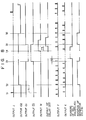
- Figs. 8 to 15 are views for explaining the operation of the apparatus shown in Fig. 1.
- An embodiment of the present invention will now be described with reference to the accompanying drawings.
- Fig. 1 is a partially cutaway side view showing the main part of a stacking apparatus for paper sheets according to an embodiment of the present invention, and Fig. 2 is a cross-sectional view of the apparatus along the line II - II of Fig. 1;
- Referring to Figs. 1 and 2, reference numeral 1 denotes a vertical base plate. A pair of
support plates support plates support plates support plates - The outer rings of
bearings support plates hollow pulley 4 is rotatably mounted on the inner rings of thebearings endless belt 5 is looped around the outer surface of thepulley 4 at one side and is coupled to a driving source (not shown) at the other side, so that the pulley is driven at a predetermined speed. Blade wheel means (i.e., a pair of blade wheels) are coaxially coupled by bolts 8 on the shaft at the two end surfaces of thepulley 4, throughspacers blade wheels paper sheet 16. Holes 9 are respectively formed at the centers of theblade wheels pulley 4.Elongated blades 10 extend in a direction opposite to the rotational direction of thewheels wheels blades 10 draw an involute curve, as shown in Fig. 1. Eachelongated space 11 is formed between every twoadjacent blades 10. Theblade wheels pulley 4 such that thespaces 11 of theblade wheels shaft 13. - The outer rings of
bearings 12a and 12b are coaxially mounted at two ends of the inner surface of thepulley 4. Theshaft 13 is rotatably mounted on the inner rings of thebearings 12a and 12b. One end of theshaft 13 extends outside theblade wheel 7b without being brought into contact with the hole 9 therein. The other end of theshaft 13 also extends outside theblade wheel 7a without being brought into contact with the hole 9 therein and is coupled to the rotating shaft of apulse motor 14 mounted on the base plate 1. A pair ofseparators shaft 13 to sandwich theblade wheels - As illustrated separately in Fig. 3, the
separators arms 22 and receiving portions or receivinghands 23. Thearms 22 are parallel to the outer side surfaces of theblade wheels arms 22 parallel to theshaft 13, towards theblade wheels shaft 13, protruding by a length more than half that of thepaper sheet 16 along theblades 10 of theblade wheels separators arms 22 are disposed on the same plane. Proximal ends 22a of thearms 22 are mounted on theshaft 13 such that a distance S (Fig. 3) between thearms 22 is longer than the width W of thepaper sheet 16. In this condition, the receiving portions (i.e., the receiving hands 23) are spaced apart from each other by a distance H which is equal to the distance between theblade wheels hands 23 are integrally formed with thearms 22. The receivinghands 23 are located outside imaginary circles drawn by theblade wheels - A transporting or conveyer belt mechanism 31 (Fig. 1) is disposed in the upper portion between the
blade wheels paper sheet 16 into the correspondingspaces 11 of theblade wheels belt mechanism 31, as the feeding means, comprises: apulley 32 disposed between theblade wheels shaft 13; twolower belts 34 looped around thepulley 32, parallel to each other at two different positions along a direction perpendicular to the drawing surface (Fig. 1), and guided through thepulley 32 along the direction of anarrow 33; twoupper belts 36 guided in the direction of anarrow 35 up to thepulley 32, while theupper belts 36 overlap the upper surfaces of thelower belts 34 so as to transport thepaper sheet 16 in a clamped manner in the overlapping interval; and apulley 37 for turning back theupper belts 36 above thepulley 32. Therefore, the position where thelower belts 34 are separated from the upper belts 36 (i.e., the position where the paper sheet is fed) is located inside the peripheral edges of theblade wheels pulleys lower belts blade wheels - On the other hand, a stacking
unit 41, as the stacking means, is disposed below theblade wheels unit 41 comprises: bearings 42a and 42b whose outer rings are mounted in the lower portions of thesupport plates shaft 13; a shaft 43 mounted in the inner rings of the bearings 42a and 42b;pulleys belts belt 45c is shown to extend to the left, as illustrated in Fig. 1) looped around thepulleys - One end of a
bar 51 is fixed on theshaft 13 at a position near thepulse motor 14 and detects the positions of theseparators bar 51 has substantially an equal width (along the peripheral direction) to that of thearm 22 of each of theseparators bar 51 is fixed to theshaft 13 such that thebar 51 extends in the same direction as that of thearm 22. As shown in Fig. 2,separator detectors bar 51 while thebar 51 is not brought into contact with theseparator detectors separator detectors separator detectors element 53 and a light-receivingelement 54, which are linearly aligned opposing each other, as shown in Fig. 4. Each of theseparator detectors bar 51 is inserted between thecorresponding elements element 54. Otherwise, each detector generates a high level signal. Therefore, theseparator detector 52a generates a low level signal when the bar 51 (i.e., thearm 22 of theseparators 21b (21a)) is located at a position indicated by the dotted circle B in Fig. 1. Similarly, theseparator detector 52b generates a low level signal when thearm 22 of theseparator 21b (21a) is located at a position indicated by the dotted circle C in Fig. 1. The positions B and C will be described in detail later. A recess 55 (Fig. 2) is formed in the surface of thesupport plate 2a which opposes the inner surface of theblade wheel 7a. - A
pulse generator 56 is arranged in therecess 55 to generate pulses in synchronism with the rotation of theblade wheels pulse generator 56 comprises a photocoupler consisting of a light-emittingelement 57 for emitting light towards the inner surface of theblade wheel 7a at a predetermined angle, and a light-receivingelement 58 for receiving light reflected by the inner surface of theblade wheel 7a. As shown in Fig. 6, a plurality of apertures 59 is formed in a circular shape on the portion of theblade wheel 7a which receives the reflected light. The apertures 59 are formed at positions falling on lines connecting acenter 60 of theblade wheel 7a andtips 61 of theblades 10. Thepulse generator 56 generates an output signal when incident light on thelight receiving element 58 transmited from the light-emittingelement 57 through one of the apertures 59 is cut off. Apaper number detector 63 is disposed in the vicinity of the feeding port of thepaper sheet 16, in the overlapping portion between the upper andlower belts belt mechanism 31, to count the number ofpaper sheets 16 conveyed while being clamped between thebelts detector 63 comprises a light-emitting element 64 and a light-receivingelement 65, which are disposed below and above the overlapping portion of thebelts belts - A paper flow detector 66 (Fig. 1) is arranged in the part of the overlapping portion, which is located upstream of the
detector 63, and detects the flow of apaper sheet 16 clamped between thebelts element 67 and a light-receiving element 68, which are arranged below and above thebelts belts paper sheet 16 has passed through it. A stacking detector 69 (Fig. 1) is disposed in the vicinity of the stackingunit 41. Thedetector 69 is arranged such that a light-emittingelement 70 and a light-receiving element 71 are placed on an oblique line on a plane perpendicular to theshaft 13, as shown in Fig. 1. When the light-receiving element 71 receives light from the light-emittingelement 70, it generates an output signal. - Outputs El and E2 from the
separator detectors pulse generator 56, an output J from thedetector 63, an output K from the detector 66, and an output M from thedetector 69 are supplied to acontrol unit 81 as the controlling means for driving thepulse motor 14 and thebelts unit 41. Thecontrol unit 81, has a detailed configuration, as shown in Fig. 7. Thecontrol unit 81 has sixinput terminals detector 52a is supplied to theinput terminal 82 and to one input terminal of an ANDgate 88. The output J from thedetector 63 is supplied to theinput terminal 83 and to one input terminal of an ANDgate 91 through adelay circuit 89 having a predetermined delay time and a one-shot multivibrator 90. The output F from thepulse generator 56 is supplied to theinput terminal 84 and to the other input terminal of the ANDgate 91. The output M from thedetector 69 is supplied to theinput terminal 85 and to the second input terminal of an ANDgate 93 through adelay circuit 92. The output K from the detector 66 is supplied to the third input terminal of the ANDgate 93 through theinput terminal 86. The output El is supplied to the first input terminal of the ANDgate 93 through aninverter 94. The output E2 from thedetector 52b is supplied to theinput terminal 87 and to one input terminal of an ANDgate 95. An output from the ANDgate 91 is supplied to the other input terminal of the ANDgate 88 through a one-shot multivibrator 96. An output from the ANDgate 93 is supplied to the other input terminal of the ANDgate 95 through a one-shot multivibrator 97. A pulse generator 98 (to be described in detail later) is provided for generating a pulse having a period to be described later. The output terminal of thepulse generator 98 is connected to a common node of the collectors ofnpn transistors transistors npn transistors gate 88 is commonly supplied to the bases of thetransistors gate 95 is commonly supplied to the bases of thetransistors transistor 102 is supplied as a drive control signal to adrive circuit 103 for driving thepulse motor 14. An emitter output from thetransistor 101 is supplied to acounter 104. An output from thecounter 104 is supplied to thedrive circuit 103 through a digital-to-analog converter 105 (to be referred to as a D/A converter hereinafter) and a voltage-to-frequency converter 106 (to be referred to as a V/f converter hereinafter). Thecounter 104 is reset in response to a differentiator circuit 107 for differentiating the trailing edge of the output E2. The electrical characteristics of the V/f converter 106 are preset in accordance with the position of the detector 66. An output from theinverter 94 is supplied to adifferentiator circuit 109 through adelay circuit 108. Thedifferentiator circuit 109 differentiates the leading edge of the output from thedelay circuit 108. An output from thedifferentiator circuit 109 is supplied as a drive signal to a one-shot multivibrator 110. An output from the one-shot multivibrator 110 is supplied as a control signal to adrive circuit 111 for driving amotor 112 for moving thebelts unit 41. - The operation of the stacking apparatus, having the construction described above, will be described with reference to Figs. 8 to 15.
- Assume that the apparatus handles 1,200 paper sheets per minute. In order to satisfy the above assumption, the travel speed of the
belt mechanism 31 and the feeding of thepaper sheet 16 into themechanism 31 must be preset such that a time interval is given to be 50 msec, during which the leading edge of a given paper sheet, transported by thebelt mechanism 31, passes a given position and the leading edge of the next paper sheet reaches the given position. In this case, assume that a time interval is 25 msec, during which the trailing edge of the given paper sheet passes the given position and the leading edge of the next paper sheet reaches the given position. In order to satisfy the above condition, the rotational speed of theblade wheels spaces 11, the angle a of rotation of the blade wheel, corresponding to one space, is 30 degrees. This angular displacement is performed for a time interval of 50 msec, so the rotational speed N of each of theblade wheels blade wheels arrow 120 in Fig. 1, and thebelts arrows - Now assume that the
separators separator 21b which is aligned with theseparator detector 52b as indicated by the dotted circle C in Fig. 1) where theseparators belt mechanism 31 in the rotational direction of theblade wheels arms 22 of theseparators paper sheet 16. The receivinghands 23 are located outside the peripheral edges of theblade wheels separators belt mechanism 31 and which is ready for insertion into the correspondingspace 11 of theblade wheels paper sheet 16 is inserted from its leading edge into thespace 11 whether or not theseparators paper sheet 16 into thespace 11 is decreased since the space forms an arc shape, so that thepaper sheet 16 is entirely inserted in thespace 11. Thepaper sheet 16 is rotated with the rotation of theblade wheels paper sheet 16 is rotated through about 180 degrees, the leading edge of thepaper sheet 16 abuts against the left end surfaces 2c of thesupport plates blade wheels blade wheels paper sheet 16 is gradually removed such that the rear edge side is discharged first from thespace 11. The discharged paper sheet naturally drops in the horizontal state onto thebelts belts - In this state, since the
arms 22 of theseparators detector 52b, the optical path of the photocoupler is blocked by thebar 51. Therefore, the output from thedetector 52b is held at low level. However, the optical path of thedetector 52a is not blocked, so that thedetector 52a generates the high output El. The pulse generator 56 (Fig. 2) has the apertures 59 (Fig. 6) as previously described, so that thepulse generator 56 generates the output pulses F having a period of 50 ms. Similarly, the detector 66 generates the output pulses K having a period of 50 ms. - When the
detector 63 detects the trailing edge of a 101st sheet following the predetermined number of 100 sheets, while thepaper sheets 16 are sequentially stacked, thedetector 63 generates the output pulse J as shown in the Fig. 8. The 101st sheet is the first sheet included in the next stack of sheets. The output pulse J is supplied to one input terminal of the ANDgate 91 through thedelay circuit 89 and the one-shot multivibrator 90 in the control unit or control means 81. - A delay time T1 of the
delay circuit 89 is preset as follows. Assume in Fig. 10 that apaper sheet 16a, inserted in a space lla betweenblades 10a and 10b, is the 101st paper sheet. The delay time Tl is preset tq be a time interval between a moment at which the trailing edge of the 101st paper sheet crosses the optical path of the detector 63 (i.e., tl) and a moment at whichthe.tip 18 of theblade 10b, located immediately before thepaper sheet 16a, is aligned with the central axis R of thearms 22 of theseparators tip 18 of theblade 10b is rotated to align with the central axis R (i.e., when the tip of thepaper sheet 16a passes by thearms 22 of theseparators pulse generator 56 generates the output pulse F, as is apparent from the positional relationship between the apertures 59 shown in Fig. 6. This moment is given to be t2. The ANDgate 91 is enabled in response to an output F2 at time t2, so that the one-shot multivibrator 96 is driven. On the other hand, at time t2, the output El of thedetector 52a is at high level. The ANDgate 88 is enabled at time t2, so that thetransistors pulse generator 98 is supplied to control thedrive circuit 103 through thetransistors pulse motor 14 is rotated to turn theseparators pulse generator 98 is constructed to generate pulses of a period such that the rotational speed of theblade wheels pulse motor 14. Therefore, theseparators blade wheels arms 22 is aligned with thetip 18 of theblade 10b, as shown in Fig. 11. - When the
separators detector 52a which is indicated as a dotted circle B in Fig. 12), thebar 51 blocks the optical path of the photocoupler of thedetector 52a, so that the output El of thedetector 52a becomes low. As a result, the ANDgate 88 is closed or disabled, and thetransistors pulse motor 14 then stops. This stop position is called a receiving position. Theseparator 21b (21a) stops at the position shown in Fig. 12. Meanwhile, the leading edge of the101st paper sheet 16a inserted in the space lla between theblades 10a and 10b, until theseparators support plates separators arms 22 is located at the side of the tip 18a of theblade 10b, so that the 101st paper sheet removed from the space lla cannot drop downward but is received by thehands 23 of theseparators separators blade wheels 101st paper sheet 16a by the receivinghands 23, so that the 101st and subsequent paper sheets are sequentially stacked on the receiving hands 23. - When the
separators detector 52a lowers, an output EI from theinverter 94 rises. The output E1 is supplied to thedelay circuit 108 and thedifferentiator circuit 109 for differentiating the leading edge of the output from thedelay circuit 108. The output from thedifferentiator circuit 109 is supplied as the control signal for thedrive circuit 111 of themotor 112 through the one-shot multivibrator 110. For this reason, when a time interval T2 has elapsed to give time t3, themotor 112 is started with the result that thebelts shot multivibrator 110 in the direction indicated by an arrow 121 (Fig. 13). Therefore, the stack ofpaper sheets 16 below theblade wheels delay circuit 108 is preset to correspond to the time taken for the 100paper sheets 16 to be completely cleared away. While the paper sheets stacked on thebelts paper sheets 16 are sequentially stacked on the receiving hands 23. - When the stack on the
belts blade wheels detector 69 rises. The output M is supplied to the ANDgate 93 through thedelay circuit 92. The delay time T3 of thedelay circuit 92 is preset to correspond to the time interval between time t4 when the output M rises and the time when thebelts delay circuit 92 rises, the output El from theinverter 94 is at a high level. - In this state, when a time interval has elapsed to give time t5, the detector 66 generates the output K, and the AND
gate 93 is enabled. Therefore, the one-shot multivibrator 97 is driven. In this case, the output E2 from thedetector 52b is set at high level, so that the ANDgate 95 is enabled at time t5 to turn on thetransistors pulse generator 98 is supplied to acontrol pulse system 120 through thetransistors control pulse system 120 comprises thecounter 104, the D/A converter 105 and the V/f converter 106, which are connected in series, and serves to move the separators from the lower position of Fig. 12 to the upper position of Fig. 15 at the time of acceleration. Details of this will be described later. Thecounter 104 in the control pulse system orcontrol circuit 120 counts the pulses from thepulse generator 98 and supplies a count signal to the D/A converter 105. The D/A converter 105 generates a voltage corresponding to the count signal. This voltage from the D/A converter 105 is applied to the V/f converter 106, which converts it into a pulse signal having a pulse recurrence frequency corresponding to the output of the D/A converter. This signal is supplied to thepulse motor 14 through thedrive circuit 103. Therefore, when thecounter 104 starts counting the pulses generated from thepulse generator 98, thepulse motor 14 is also started from the stop state at a speed corresponding to the elapsed time. Therefore, thepulse motor 14 is started again from time t5, and theseparators blade wheels paper sheets 16 stacked on the receivinghands 23 of theseparators belts - The
control pulse system 120, comprising thecounter 104, the D/A converter 105 and the V/f converter 106, is operated as follows. Assume that a position where the optical axis of the photocoupler of the detector 66 crosses thebelt mechanism 31 is given to be X, that a position where a track Z of the receivinghands 23 crosses thebelt mechanism 31 when theseparators belt mechanism 31 is predetermined, a time interval Tℓ, during which the trailing end of thepaper sheet 16 passes both X and Y, is constant. Therefore, when the paper sheets transported by thebelt mechanism 31 have given intervals therebetween, the paper sheet which passes the position Y is not present during the given interval after the immediately preceding paper sheet passes through the position Y. This given time interval occures every 50 ms. In this embodiment, as shown in' the right half portion of Fig. 9, after thepulse motor 14 is started at time t5, the rotational force is increased with a predetermined torque rate. Immediately before a time interval Ti from time t5 has elapsed, the control pulse system is operated such that the receivinghands 23 of theseparators belt mechanism 31. At the time of acceleration of theseparators pulse motor 14 since the paper sheets are not stacked on the receivinghands 23 of theseparators hands 23 are not brought into contact with thepaper sheets 16 transferred through thebelt mechanism 31 and pass through the space between the sheets and past position Y, moving smoothly from the lower position of thebelts pulse motor 14 when theseparators separators separators separators - The
separators hands 23 extend above theblade wheels arms 22 reach at the side of thedetector 52b, so that thebar 51 blocks the optical path of the photocoupler of thedetector 52b at time t6. At this time, the output E2 from thedetector 52b lowers. As a result, the ANDgate 95 is closed to turn off thetransistors counter 104 is reset in response to the output from the differentiator circuit 107. - Therefore, the
motor 14 is stopped, and theseparators detector 63. Therefore, thepaper sheets 16, fed one by one edgewise, can be sorted in units of 100 sheets, and the 100-sheet groups are fed in the subsequent unit, thereby providing efficient handling of the stacking apparatus having the sorting means. - In the stacking apparatus of the present invention, the
arms 22 of theseparators spaces 11 of theblade wheels arms 22 will not be brought into contact with thepaper sheets 16, so that the travel path of the paper sheet to be inserted in thespace 11 will not be interfered with by thearms 22, irrespective of the positions of theseparators separators - The present invention is not limited to the above embodiment. In the above embodiment, the
separators separators hands 23 of theseparators paper sheets 16 at a speed several times the travel speed of thebelt mechanism 31. In this case, the loading torque of thepulse motor 14 is increased as compared with that in the above embodiment. However, the time interval between the time at which theseparator separators sheets 16 is short, so that the determining timing of the movement of the receivinghands 23 across the travel path of thesheet 16 can be simplified. In addition to this modification, the moving speed of theseparators blade wheels separators separators separators unit 41 are discharged, and the paper sheets stacked on the receiving hands are transferred to a substacking unit (not shown) by utilizing an open space of the receiving hands 23. Thereafter, the separator is axially moved such that the receivinghand 23 is cleared away from the lower portion of theblade wheels
Claims (10)
characterized in that
characterized in that
Priority Applications (1)
| Application Number | Priority Date | Filing Date | Title |
|---|---|---|---|
| AT84301674T ATE35126T1 (en) | 1983-03-16 | 1984-03-13 | SHEET STACKER. |
Applications Claiming Priority (2)
| Application Number | Priority Date | Filing Date | Title |
|---|---|---|---|
| JP42344/83 | 1983-03-16 | ||
| JP58042344A JPS59172354A (en) | 1983-03-16 | 1983-03-16 | Paper sheet collecting unit |
Publications (3)
| Publication Number | Publication Date |
|---|---|
| EP0119814A2 true EP0119814A2 (en) | 1984-09-26 |
| EP0119814A3 EP0119814A3 (en) | 1985-09-18 |
| EP0119814B1 EP0119814B1 (en) | 1988-06-15 |
Family
ID=12633400
Family Applications (1)
| Application Number | Title | Priority Date | Filing Date |
|---|---|---|---|
| EP84301674A Expired EP0119814B1 (en) | 1983-03-16 | 1984-03-13 | Stacking apparatus for paper sheets |
Country Status (6)
| Country | Link |
|---|---|
| US (1) | US4595193A (en) |
| EP (1) | EP0119814B1 (en) |
| JP (1) | JPS59172354A (en) |
| AT (1) | ATE35126T1 (en) |
| CA (1) | CA1211132A (en) |
| DE (1) | DE3472093D1 (en) |
Cited By (6)
| Publication number | Priority date | Publication date | Assignee | Title |
|---|---|---|---|---|
| FR2664581A1 (en) * | 1990-07-12 | 1992-01-17 | Dassault Electronique | Device for processing securities, such as banknotes, with a bladed wheel with discontinuous movement |
| EP0647583A2 (en) * | 1993-09-20 | 1995-04-12 | Kabushiki Kaisha Toshiba | Apparatus for inspecting sheet materials and conveying device used therefor |
| EP0708419A1 (en) | 1994-10-21 | 1996-04-24 | Giesecke & Devrient GmbH | Method and apparatus for processing bank notes |
| DE10234970B4 (en) * | 2002-07-31 | 2005-04-28 | Giesecke & Devrient Gmbh | Method and device for stacking sheet material |
| US7624983B2 (en) | 2004-05-11 | 2009-12-01 | Giesecke & Devrient Gmbh | Device and method for stacking sheets |
| CN103167996A (en) * | 2010-08-10 | 2013-06-19 | 瑞特有限责任公司 | Apparatus and method for feeding stacks of tissues or similar folded products to an automatic packaging system |
Families Citing this family (19)
| Publication number | Priority date | Publication date | Assignee | Title |
|---|---|---|---|---|
| US4736936A (en) * | 1987-01-16 | 1988-04-12 | Paper Converting Machine Company | Hanky delivery system |
| US5088720A (en) * | 1987-01-16 | 1992-02-18 | The Mead Corporation | Envelope handling system |
| US4930977A (en) * | 1987-01-16 | 1990-06-05 | The Mead Corporation | Envelope handling system |
| US5040783A (en) * | 1990-09-10 | 1991-08-20 | The Procter & Gamble Company | Rotary stacker |
| IL101215A (en) * | 1992-03-13 | 1995-12-31 | Scitex Corp Ltd | Flexible sheet storage device |
| JP4497657B2 (en) * | 2000-05-19 | 2010-07-07 | 株式会社ミヤコシ | Sheet sorting set out device |
| ITBO20000475A1 (en) * | 2000-07-31 | 2002-01-31 | Cat System S R L | DEVICE FOR THE SEPARATION OF GROUPS OF SHEETS IN AN APPARATUS FOR THE FORMATION AND BANDING OF GROUPS OF SHEETS, SUCH AS |
| US6832886B2 (en) | 2001-07-27 | 2004-12-21 | C. G. Bretting Manufacturing Co., Inc. | Apparatus and method for stacking sheets discharged from a starwheel assembly |
| US6808361B1 (en) | 2002-03-27 | 2004-10-26 | John T. McCarthy | Apparatus and method for stacking food portions |
| US6877740B2 (en) | 2003-07-30 | 2005-04-12 | C.G. Bretting Manufacturing Company, Inc. | Starwheel feed apparatus and method |
| DE10341588A1 (en) * | 2003-09-09 | 2005-03-31 | Giesecke & Devrient Gmbh | Spiral panel stacker for sheets, esp. banknotes, has separator introduced between n-th and following sheets and shifted synchronously with stacker wheel rotation towards stacker tray |
| CN100373154C (en) * | 2004-05-10 | 2008-03-05 | 中国印钞造币总公司 | Method for detecting consecutive number |
| KR100608078B1 (en) * | 2004-07-16 | 2006-08-08 | 엘지엔시스(주) | A media dispenser |
| JP2007058764A (en) * | 2005-08-26 | 2007-03-08 | Toshiba Corp | Paper sheet accumulation device |
| US20070257427A1 (en) * | 2005-12-16 | 2007-11-08 | Ncr Corporation | Stacker wheel |
| WO2010112794A1 (en) * | 2009-04-02 | 2010-10-07 | De La Rue International Limited | Apparatus and method for forming and strapping stacks of sheet documents |
| CN103400442B (en) * | 2013-08-05 | 2015-11-25 | 广州广电运通金融电子股份有限公司 | Financial self-service equipment and vane type banknote separating device thereof |
| CN103559762B (en) * | 2013-11-05 | 2016-01-20 | 广州广电运通金融电子股份有限公司 | A kind of vane type paper money temporary mechanism, bank note treatment device and automatic teller machine |
| CN106927284B (en) * | 2015-12-31 | 2019-05-21 | 上海东冠纸业有限公司 | A kind of napkin paper machine point paper device |
Citations (3)
| Publication number | Priority date | Publication date | Assignee | Title |
|---|---|---|---|---|
| DE2461002B1 (en) * | 1974-12-21 | 1976-04-29 | Schickedanz Ver Papierwerk | Stacking machine for paper tissues - includes wheel with rotating plates and basket system rotating at differing speeds |
| EP0059101A1 (en) * | 1981-02-24 | 1982-09-01 | Kabushiki Kaisha Toshiba | Stacking device for paper sheets |
| EP0102814A2 (en) * | 1982-09-03 | 1984-03-14 | Kabushiki Kaisha Toshiba | Paper-sheet dividing apparatus |
Family Cites Families (4)
| Publication number | Priority date | Publication date | Assignee | Title |
|---|---|---|---|---|
| DE1079078B (en) * | 1957-11-19 | 1960-04-07 | Winkler Fallert & Co Maschf | Package delivery with delivery stars for delivery of folded or unfolded sheets of paper in packages |
| US4228997A (en) * | 1978-06-23 | 1980-10-21 | Eastman Kodak Company | Stacking machine |
| US4501418A (en) * | 1981-02-24 | 1985-02-26 | Tokyo Shibaura Denki Kabushiki Kaisha | Stacking device for paper sheets |
| JPS59101A (en) * | 1982-06-24 | 1984-01-05 | Mitsubishi Electric Corp | Fresnel lens |
-
1983
- 1983-03-16 JP JP58042344A patent/JPS59172354A/en active Granted
-
1984
- 1984-03-12 US US06/588,364 patent/US4595193A/en not_active Expired - Lifetime
- 1984-03-13 AT AT84301674T patent/ATE35126T1/en not_active IP Right Cessation
- 1984-03-13 EP EP84301674A patent/EP0119814B1/en not_active Expired
- 1984-03-13 DE DE8484301674T patent/DE3472093D1/en not_active Expired
- 1984-03-14 CA CA000449627A patent/CA1211132A/en not_active Expired
Patent Citations (3)
| Publication number | Priority date | Publication date | Assignee | Title |
|---|---|---|---|---|
| DE2461002B1 (en) * | 1974-12-21 | 1976-04-29 | Schickedanz Ver Papierwerk | Stacking machine for paper tissues - includes wheel with rotating plates and basket system rotating at differing speeds |
| EP0059101A1 (en) * | 1981-02-24 | 1982-09-01 | Kabushiki Kaisha Toshiba | Stacking device for paper sheets |
| EP0102814A2 (en) * | 1982-09-03 | 1984-03-14 | Kabushiki Kaisha Toshiba | Paper-sheet dividing apparatus |
Cited By (11)
| Publication number | Priority date | Publication date | Assignee | Title |
|---|---|---|---|---|
| FR2664581A1 (en) * | 1990-07-12 | 1992-01-17 | Dassault Electronique | Device for processing securities, such as banknotes, with a bladed wheel with discontinuous movement |
| EP0647583A2 (en) * | 1993-09-20 | 1995-04-12 | Kabushiki Kaisha Toshiba | Apparatus for inspecting sheet materials and conveying device used therefor |
| EP0647583A3 (en) * | 1993-09-20 | 1995-07-19 | Tokyo Shibaura Electric Co | Apparatus for inspecting sheet materials and conveying device used therefor. |
| US5641156A (en) * | 1993-09-20 | 1997-06-24 | Kabushiki Kaisha Toshiba | Apparatus for inspecting sheet materials and conveying device used therefor |
| EP0708419A1 (en) | 1994-10-21 | 1996-04-24 | Giesecke & Devrient GmbH | Method and apparatus for processing bank notes |
| US5894937A (en) * | 1994-10-21 | 1999-04-20 | Giesecke & Devrient Gmbh | Method and apparatus for processing bank notes |
| DE10234970B4 (en) * | 2002-07-31 | 2005-04-28 | Giesecke & Devrient Gmbh | Method and device for stacking sheet material |
| US7624983B2 (en) | 2004-05-11 | 2009-12-01 | Giesecke & Devrient Gmbh | Device and method for stacking sheets |
| CN1989057B (en) * | 2004-05-11 | 2010-12-15 | 德国捷德有限公司 | Device and method for stacking sheets |
| CN103167996A (en) * | 2010-08-10 | 2013-06-19 | 瑞特有限责任公司 | Apparatus and method for feeding stacks of tissues or similar folded products to an automatic packaging system |
| CN103167996B (en) * | 2010-08-10 | 2015-11-25 | 瑞特有限责任公司 | For paper handkerchief being fed into the equipment of automatic packaging system |
Also Published As
| Publication number | Publication date |
|---|---|
| CA1211132A (en) | 1986-09-09 |
| ATE35126T1 (en) | 1988-07-15 |
| JPS59172354A (en) | 1984-09-29 |
| JPS6334103B2 (en) | 1988-07-08 |
| US4595193A (en) | 1986-06-17 |
| EP0119814B1 (en) | 1988-06-15 |
| DE3472093D1 (en) | 1988-07-21 |
| EP0119814A3 (en) | 1985-09-18 |
Similar Documents
| Publication | Publication Date | Title |
|---|---|---|
| US4595193A (en) | Stacking apparatus for paper sheets | |
| US4593896A (en) | Stacking apparatus for paper sheets | |
| US4470590A (en) | Stacking device for paper sheets | |
| EP0017983B1 (en) | Sheet transport apparatus | |
| US4501418A (en) | Stacking device for paper sheets | |
| KR900000787B1 (en) | Paper sheet collecting apparatus | |
| US4603849A (en) | Paper-sheet dividing apparatus | |
| US4088314A (en) | Synchronous stacking device | |
| EP0472410B1 (en) | Fabric turner | |
| JPH0343182B2 (en) | ||
| JPH01162670A (en) | Sorting stacker for stock | |
| US6554273B1 (en) | Method and device for forming a wad of individual sheets | |
| US5641156A (en) | Apparatus for inspecting sheet materials and conveying device used therefor | |
| JP2767290B2 (en) | Paper sheet reversing device | |
| JP4146776B2 (en) | Card processing device | |
| JPH0313145B2 (en) | ||
| US20240010456A1 (en) | Stacking apparatus, stacking method, and stacking system | |
| JPS6056768A (en) | Retrieving device for sheet | |
| GB2176173A (en) | Feeding paper to a shredding machine | |
| JPH0362621B2 (en) | ||
| JP2679578B2 (en) | Integrated feeding device for paper sheets | |
| JPS58177852A (en) | Combined leaf aligning and folding apparatus | |
| JPH0684039A (en) | Coin processing machine | |
| JPH06127783A (en) | Ticket recovering device | |
| JPH0313146B2 (en) |
Legal Events
| Date | Code | Title | Description |
|---|---|---|---|
| PUAI | Public reference made under article 153(3) epc to a published international application that has entered the european phase |
Free format text: ORIGINAL CODE: 0009012 |
|
| 17P | Request for examination filed |
Effective date: 19840326 |
|
| AK | Designated contracting states |
Designated state(s): AT CH DE FR GB IT LI NL SE |
|
| PUAL | Search report despatched |
Free format text: ORIGINAL CODE: 0009013 |
|
| AK | Designated contracting states |
Designated state(s): AT CH DE FR GB IT LI NL SE |
|
| 17Q | First examination report despatched |
Effective date: 19860423 |
|
| R17C | First examination report despatched (corrected) |
Effective date: 19870203 |
|
| GRAA | (expected) grant |
Free format text: ORIGINAL CODE: 0009210 |
|
| AK | Designated contracting states |
Kind code of ref document: B1 Designated state(s): AT CH DE FR GB IT LI NL SE |
|
| REF | Corresponds to: |
Ref document number: 35126 Country of ref document: AT Date of ref document: 19880715 Kind code of ref document: T |
|
| ITF | It: translation for a ep patent filed |
Owner name: JACOBACCI & PERANI S.P.A. |
|
| REF | Corresponds to: |
Ref document number: 3472093 Country of ref document: DE Date of ref document: 19880721 |
|
| ET | Fr: translation filed | ||
| PLBE | No opposition filed within time limit |
Free format text: ORIGINAL CODE: 0009261 |
|
| STAA | Information on the status of an ep patent application or granted ep patent |
Free format text: STATUS: NO OPPOSITION FILED WITHIN TIME LIMIT |
|
| 26N | No opposition filed | ||
| ITTA | It: last paid annual fee | ||
| EAL | Se: european patent in force in sweden |
Ref document number: 84301674.2 |
|
| PGFP | Annual fee paid to national office [announced via postgrant information from national office to epo] |
Ref country code: GB Payment date: 19970304 Year of fee payment: 14 |
|
| PGFP | Annual fee paid to national office [announced via postgrant information from national office to epo] |
Ref country code: FR Payment date: 19970313 Year of fee payment: 14 Ref country code: AT Payment date: 19970313 Year of fee payment: 14 |
|
| PGFP | Annual fee paid to national office [announced via postgrant information from national office to epo] |
Ref country code: SE Payment date: 19970319 Year of fee payment: 14 |
|
| PGFP | Annual fee paid to national office [announced via postgrant information from national office to epo] |
Ref country code: CH Payment date: 19970320 Year of fee payment: 14 |
|
| PGFP | Annual fee paid to national office [announced via postgrant information from national office to epo] |
Ref country code: NL Payment date: 19970327 Year of fee payment: 14 |
|
| PG25 | Lapsed in a contracting state [announced via postgrant information from national office to epo] |
Ref country code: GB Free format text: LAPSE BECAUSE OF NON-PAYMENT OF DUE FEES Effective date: 19980313 Ref country code: AT Free format text: LAPSE BECAUSE OF NON-PAYMENT OF DUE FEES Effective date: 19980313 |
|
| PG25 | Lapsed in a contracting state [announced via postgrant information from national office to epo] |
Ref country code: SE Free format text: LAPSE BECAUSE OF NON-PAYMENT OF DUE FEES Effective date: 19980314 |
|
| PG25 | Lapsed in a contracting state [announced via postgrant information from national office to epo] |
Ref country code: LI Free format text: LAPSE BECAUSE OF NON-PAYMENT OF DUE FEES Effective date: 19980331 Ref country code: FR Free format text: THE PATENT HAS BEEN ANNULLED BY A DECISION OF A NATIONAL AUTHORITY Effective date: 19980331 Ref country code: CH Free format text: LAPSE BECAUSE OF NON-PAYMENT OF DUE FEES Effective date: 19980331 |
|
| PG25 | Lapsed in a contracting state [announced via postgrant information from national office to epo] |
Ref country code: NL Free format text: LAPSE BECAUSE OF NON-PAYMENT OF DUE FEES Effective date: 19981001 |
|
| GBPC | Gb: european patent ceased through non-payment of renewal fee |
Effective date: 19980313 |
|
| REG | Reference to a national code |
Ref country code: CH Ref legal event code: PL |
|
| NLV4 | Nl: lapsed or anulled due to non-payment of the annual fee |
Effective date: 19981001 |
|
| EUG | Se: european patent has lapsed |
Ref document number: 84301674.2 |
|
| REG | Reference to a national code |
Ref country code: FR Ref legal event code: ST |
|
| PGFP | Annual fee paid to national office [announced via postgrant information from national office to epo] |
Ref country code: DE Payment date: 20030320 Year of fee payment: 20 |