EP0119084A2 - Aerosol actuator - Google Patents
Aerosol actuator Download PDFInfo
- Publication number
- EP0119084A2 EP0119084A2 EP84301625A EP84301625A EP0119084A2 EP 0119084 A2 EP0119084 A2 EP 0119084A2 EP 84301625 A EP84301625 A EP 84301625A EP 84301625 A EP84301625 A EP 84301625A EP 0119084 A2 EP0119084 A2 EP 0119084A2
- Authority
- EP
- European Patent Office
- Prior art keywords
- actuator
- actuating member
- inoperative
- condition
- movable
- Prior art date
- Legal status (The legal status is an assumption and is not a legal conclusion. Google has not performed a legal analysis and makes no representation as to the accuracy of the status listed.)
- Withdrawn
Links
Images


Classifications
-
- B—PERFORMING OPERATIONS; TRANSPORTING
- B65—CONVEYING; PACKING; STORING; HANDLING THIN OR FILAMENTARY MATERIAL
- B65D—CONTAINERS FOR STORAGE OR TRANSPORT OF ARTICLES OR MATERIALS, e.g. BAGS, BARRELS, BOTTLES, BOXES, CANS, CARTONS, CRATES, DRUMS, JARS, TANKS, HOPPERS, FORWARDING CONTAINERS; ACCESSORIES, CLOSURES, OR FITTINGS THEREFOR; PACKAGING ELEMENTS; PACKAGES
- B65D83/00—Containers or packages with special means for dispensing contents
- B65D83/14—Containers or packages with special means for dispensing contents for delivery of liquid or semi-liquid contents by internal gaseous pressure, i.e. aerosol containers comprising propellant for a product delivered by a propellant
- B65D83/16—Containers or packages with special means for dispensing contents for delivery of liquid or semi-liquid contents by internal gaseous pressure, i.e. aerosol containers comprising propellant for a product delivered by a propellant characterised by the actuating means
- B65D83/20—Containers or packages with special means for dispensing contents for delivery of liquid or semi-liquid contents by internal gaseous pressure, i.e. aerosol containers comprising propellant for a product delivered by a propellant characterised by the actuating means operated by manual action, e.g. button-type actuator or actuator caps
- B65D83/205—Actuator caps, or peripheral actuator skirts, attachable to the aerosol container
- B65D83/206—Actuator caps, or peripheral actuator skirts, attachable to the aerosol container comprising a cantilevered actuator element, e.g. a lever pivoting about a living hinge
-
- B—PERFORMING OPERATIONS; TRANSPORTING
- B65—CONVEYING; PACKING; STORING; HANDLING THIN OR FILAMENTARY MATERIAL
- B65D—CONTAINERS FOR STORAGE OR TRANSPORT OF ARTICLES OR MATERIALS, e.g. BAGS, BARRELS, BOTTLES, BOXES, CANS, CARTONS, CRATES, DRUMS, JARS, TANKS, HOPPERS, FORWARDING CONTAINERS; ACCESSORIES, CLOSURES, OR FITTINGS THEREFOR; PACKAGING ELEMENTS; PACKAGES
- B65D83/00—Containers or packages with special means for dispensing contents
- B65D83/14—Containers or packages with special means for dispensing contents for delivery of liquid or semi-liquid contents by internal gaseous pressure, i.e. aerosol containers comprising propellant for a product delivered by a propellant
- B65D83/16—Containers or packages with special means for dispensing contents for delivery of liquid or semi-liquid contents by internal gaseous pressure, i.e. aerosol containers comprising propellant for a product delivered by a propellant characterised by the actuating means
- B65D83/22—Containers or packages with special means for dispensing contents for delivery of liquid or semi-liquid contents by internal gaseous pressure, i.e. aerosol containers comprising propellant for a product delivered by a propellant characterised by the actuating means with a mechanical means to disable actuation
-
- B—PERFORMING OPERATIONS; TRANSPORTING
- B65—CONVEYING; PACKING; STORING; HANDLING THIN OR FILAMENTARY MATERIAL
- B65D—CONTAINERS FOR STORAGE OR TRANSPORT OF ARTICLES OR MATERIALS, e.g. BAGS, BARRELS, BOTTLES, BOXES, CANS, CARTONS, CRATES, DRUMS, JARS, TANKS, HOPPERS, FORWARDING CONTAINERS; ACCESSORIES, CLOSURES, OR FITTINGS THEREFOR; PACKAGING ELEMENTS; PACKAGES
- B65D83/00—Containers or packages with special means for dispensing contents
- B65D83/14—Containers or packages with special means for dispensing contents for delivery of liquid or semi-liquid contents by internal gaseous pressure, i.e. aerosol containers comprising propellant for a product delivered by a propellant
- B65D83/56—Containers or packages with special means for dispensing contents for delivery of liquid or semi-liquid contents by internal gaseous pressure, i.e. aerosol containers comprising propellant for a product delivered by a propellant with means for preventing delivery, e.g. shut-off when inverted
-
- B—PERFORMING OPERATIONS; TRANSPORTING
- B05—SPRAYING OR ATOMISING IN GENERAL; APPLYING FLUENT MATERIALS TO SURFACES, IN GENERAL
- B05B—SPRAYING APPARATUS; ATOMISING APPARATUS; NOZZLES
- B05B11/00—Single-unit hand-held apparatus in which flow of contents is produced by the muscular force of the operator at the moment of use
- B05B11/0005—Components or details
- B05B11/0027—Means for neutralising the actuation of the sprayer ; Means for preventing access to the sprayer actuation means
-
- B—PERFORMING OPERATIONS; TRANSPORTING
- B65—CONVEYING; PACKING; STORING; HANDLING THIN OR FILAMENTARY MATERIAL
- B65D—CONTAINERS FOR STORAGE OR TRANSPORT OF ARTICLES OR MATERIALS, e.g. BAGS, BARRELS, BOTTLES, BOXES, CANS, CARTONS, CRATES, DRUMS, JARS, TANKS, HOPPERS, FORWARDING CONTAINERS; ACCESSORIES, CLOSURES, OR FITTINGS THEREFOR; PACKAGING ELEMENTS; PACKAGES
- B65D2215/00—Child-proof means
- B65D2215/04—Child-proof means requiring the combination of different actions in succession
-
- Y—GENERAL TAGGING OF NEW TECHNOLOGICAL DEVELOPMENTS; GENERAL TAGGING OF CROSS-SECTIONAL TECHNOLOGIES SPANNING OVER SEVERAL SECTIONS OF THE IPC; TECHNICAL SUBJECTS COVERED BY FORMER USPC CROSS-REFERENCE ART COLLECTIONS [XRACs] AND DIGESTS
- Y10—TECHNICAL SUBJECTS COVERED BY FORMER USPC
- Y10T—TECHNICAL SUBJECTS COVERED BY FORMER US CLASSIFICATION
- Y10T74/00—Machine element or mechanism
- Y10T74/18—Mechanical movements
- Y10T74/18856—Oscillating to oscillating
-
- Y—GENERAL TAGGING OF NEW TECHNOLOGICAL DEVELOPMENTS; GENERAL TAGGING OF CROSS-SECTIONAL TECHNOLOGIES SPANNING OVER SEVERAL SECTIONS OF THE IPC; TECHNICAL SUBJECTS COVERED BY FORMER USPC CROSS-REFERENCE ART COLLECTIONS [XRACs] AND DIGESTS
- Y10—TECHNICAL SUBJECTS COVERED BY FORMER USPC
- Y10T—TECHNICAL SUBJECTS COVERED BY FORMER US CLASSIFICATION
- Y10T74/00—Machine element or mechanism
- Y10T74/21—Elements
- Y10T74/2101—Cams
- Y10T74/2107—Follower
Definitions
- This invention relates to actuators for aerosol containers, of the kind which are fitted to the containers and which have a movable actuating portion which is depressed to operate the aerosol valve.
- Such actuators which are often referred to as “spray-dome” actuators, are to be distinguished from “button” actuators which are fitted to the valve stem of an aerosol container and which are bodily moved with the valve stem for actuation.
- the present invention seeks to provide an actuator for an aerosol container in which, with suitable arrangement, some or all of the above disadvantages may be avoided or substantially reduced. Accordingly, the invention provides an actuator for an aerosol container, which comprises upper and lower parts rotatable between a first, operative condition and a second, inoperative condition, in the operative condition of which an actuating member of the upper actuator part may be movable and effective to actuate the valve of a said container to which the actuator is fitted and thereby cause aerosol product to issue from the lower actuator part, and in the inoperative condition of which the actuating member is inoperative to cause dispensing, the lower actuator part having a movable member to actuate the valve, and the actuating member being movable to a raised position by cam action of engageable surfaces of the actuator parts when the actuator is operated from its inoperative to its operative condition, the actuating member then being depressable to actuate the aerosol valve through the agency of the said movable member, in the inoperative condition of the actuator the actu
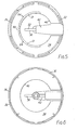
- a spray-dome actuator 10 is shown when fitted to an aerosol container 12 - shown only in part - which is of conventional design and construction and accordingly has a valve having an actuating stem 80 ( Figure 3) which projects from the top of the container on the central axis of the container.
- the actuator has upper and lower parts 14, 16 which are relatively rotatable through approximately 1800 and each of which is a one-piece moulding of high densit. polyethylene.
- the parts have equal diameter, coaxially disposed, cylindrical skirts 18, 20 generally flush with the cylindrical periphery of the container 12.
- the upper part 14 of the actuator has an arrow-shaped actuating member 22 which is mounted in a correspondingly shaped aperture 23 in its plane top panel 24 and which has barbs denoted 25.
- the actuator When, as depicted in Figure 1, the actuator is in its operative condition, the actuating member is in a raised position in which it can be depressed by the user by finger pressure on its top face 26. Product is then expelled through a nozzle 28 in the skirt 20 of the lower part 16. It will be seen that at this operative condition the actuating member is aligned with the nozzle.
- the actuator When, however, the actuator is in a non-operative position as shown in Figure 2, that is, with the upper part displaced by approximately 90 0 in either direction from the operative condition of Figure 1, the actuating member is held flush with the top panel 24 and is immovable against an attempt by a child to dispense product by depressing it further. It is in this condition that the aerosol pack (i.e. the container fitted with the actuator) is dispatched by the packer for distribution and sale.
- the aerosol pack i.e. the container fitted with the actuator
- the actuating member 22 is aligned with the nozzle 28 for dispensing, but is rotated out of approximate alignment with the nozzle when non-operation (e.g. for transit and display) and child resistance is required.
- the actuator is therefore readily operable by an adult who may easily perceive that the actuating member needs to be aligned with the nozzle prior to dispensing, but will be more difficult to operate by a young child to whom the need to align the actuating member with the nozzle will be less evident.
- the disposition of the actuating member in flush relation to the top of the actuator when the actuator is in either of its two non-operative conditions prevents damage or inadvertent operation when the container, with the actuator fitted, is in transit or on display; in particular, there is little or no danger of inadvertent actuation when the container is stacked beneath one or more other such containers, on pallets or the like.
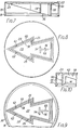
- the upper part 14 is held captive for rotation on the lower part 16 by a bead 30 on its cylindrical skirt 18 which is snap-engaged over a complementary and fragmentary bead 32 carried from a top panel 34 of the lower part above the skirt 20 of the latter.
- the lower part has a fragmented bead formed by ribs 36 which are adapted to be snap-engaged over the double-seam (not shown) by which the cone of the aerosol container is attached to the top of the container body.
- This latter engagement is such that the lower part can be rotated on the container, but usually, and as is assumed for the purposes of the following description, the actuator will be operated by the user between its operative and non-operative conditions by maintaining the lower part fixed in relation to the container, and rotating the upper part.
- the top panel 34 of the lower part is centrally apertured at 40, and in the aperture 40 is located a radially extending, generally horizontal arm 42 which is integrally hinged to the skirt 20 for pivotal movement about a hinge line 44 lying beneath the nozzle 28.
- the skirt is freed from the outer end of the arm along vertical slits 45.
- the arm At its inner end, on the central axis of the actuator, the arm carries a downwardly projecting boss 46 arranged at its free end to engage over and make sealing contact with the valve stem 80 ( Figure 3) of the aerosol container when the actuator is fitted to the container.
- the boss 46 and arm 42 are formed with connecting passages 48, 49 for product flow from the valve stem to the nozzle, and it will be understood that downward pivoting movement of the arm about the hinge line 44 will therefore operate the aerosol valve by means of the valve stem, and so cause aerosol product to be dispensed from the nozzle.
- the hinge line 44 is represented in the drawings by a broken line; however, it is to be understood that it may not be visible to the observer.
- the inner free end of the arm 42 carries an upstanding tailpiece 50.
- the actuator When, as shown in Figure 1, the actuator is in its operative condition, the top edge 52 of this tailpiece engages the bottom edge of the cross-piece 54 of a T-section structure 56 which is formed on the underside of the actuating member 22.
- the actuating member is accordingly held in its raised position by the aerosol valve of the container 12 through the agency of the arm 42.
- the actuating member 22 has a downwardly depending peripheral wall 58 at which it is hinged to a complementary but shallow wall 60 of the upper part around the aperture 23.
- the connection between the walls 58, 60 is made by a pair of integral and aligned torsion bridges 62 adjacent the front end of the actuating member.
- the actuating member is moulded in its depressed position so that these bridges resilently bias it downwards onto the tailpiece beneath.
- the effective spring rate of the bridges is, however, insufficient for the actuating member to actuate the aerosol valve by itself.
- the actuator When, as shown in Figure 2, the actuator is in one of its non-operative conditions, the actuating member is free to adopt its depressed, flush position under the bias of the bridges 62.
- the tailpiece 50 is then accommodated in the acute angle formed by the wall 58 of the actuator member at the appropriate one of its barbs 25.
- a pair of profiled ramps 64 - (one for each non-operative condition) - are moulded on the top panel 34 of the lower part 16 and engageable at their top edges 72 by the leg 66 of the T-section structure 56 previously mentioned.
- the ramps 64 are mirror images of one another on either side of a vertical slot 68 which separates their adjacent end edges 70 and which is wide enough to receive the leg 66.
- the upper edges rise progressively but gently from the top panel 34 in the direction of the slot 68, reach their maximum height at approximately 5 0 of arc from the centre of the slot, and from there fall sharply to their respective end edges 70.
- the gently and steeply inclined edge portions and the summits of the ramps are respectively denoted by the reference numerals 72A, 72B and 72C in Figure 4 of the drawings.
- the depth of the T-section structure 56 axially of the actuator is such that, when the upper part 14 of the actuator is turned to its operative condition from one of its non-operative conditions, the leg 66 rides up the appropriate ramp 64 and so is caused to lift the actuator member 22, by pivotal movement on the torsion bridges 62, sufficiently to allow the cross-piece 54 to move over the tailpiece 50 in readiness for a dispensing operation.
- the leg 66 is free to move down the slot 68 and the actuating member can be depressed for dispensing product.
- the non-operative conditions of the actuator correspond to the remote ends of the ramps 64.
- the leg 66 is then bottomed on the panel 34 to prevent depression of the actuating member. Rotational movement of the upper part beyond these positions is prevented by engagement of the tailpiece 50 behind the barbs 25 of the actuating member.
- the peripheral wall 58 of the actuating member is cut away sufficiently to clear the tailpiece 50, and the two non-operative positions of the actuator are defined by the respective separate engagements of two posts on lower part 16 with an abutment which projects inwardly from the skirt 18 of the upper part 14 adjacent the tip of the actuating member.
- the posts are moulded to project upwardly from the bed 32 at the appropriate angular positions.
- Figure 10 shows a modification of the actuator in which the peripheral wall 58 of the actuating member is extended downwardly at the top of the actuating member to form a post 90 of V-shaped cross-section which is located forward of the torsion bridges 62.
- the arms of the post at its free bottom end form rounded edges 91 which are shaped for camming engagement with the ramp 64 on the respective side of the arm 42. Therefore, when the actuator is being operated to one or the other of its non-operative positions as described above, the post 90 co-operates with the appropriate ramp 42 to force the actuating member 22 positively towards its depressed position by pivotal movement about the bridges 62.
- the torsion bridges themselves are therefore no longer relied upon- for performing this function.
Abstract
An actuator of the "spray-dome" type for an aerosol container (12) comprises upper and lower parts (14, 16) rotatable between operative and inoperative positions, the upper actuator part (14) carrying an actuator member (22) which is moved to a raised position by cam action of engageable surfaces of the actuator parts when the actuator is moved from the inoperative to the operative position, whereupon the actuating member can be depressed to actuate the aerosol valve, whereas in the inoperative position of the actuator the actuating member is in a depressed position and cannot actuate the aerosol valve.
Description
- This invention relates to actuators for aerosol containers, of the kind which are fitted to the containers and which have a movable actuating portion which is depressed to operate the aerosol valve. Such actuators, which are often referred to as "spray-dome" actuators, are to be distinguished from "button" actuators which are fitted to the valve stem of an aerosol container and which are bodily moved with the valve stem for actuation.
- It is well known to arrange spray-dome actuators so that they cannot easily be operated by a child. Such child resistance has been provided in various different ways, amongst which is the provision of two parts which are relatively rotatable between a first position in which the actuating portion is immovable or ineffective to achieve actuation, and a second position in which the actuating portion can move and is effective to achieve actuation. However,-the arrangements hitherto proposed have suffered from various disadvantages, amongst which are extreme complexity and correspondingly high moulding costs, lack of visual appeal, difficulty of operation even for an adult, and vulnerability to damage or inadvertent operation during transit or at the point of display.
- The present invention seeks to provide an actuator for an aerosol container in which, with suitable arrangement, some or all of the above disadvantages may be avoided or substantially reduced. Accordingly, the invention provides an actuator for an aerosol container, which comprises upper and lower parts rotatable between a first, operative condition and a second, inoperative condition, in the operative condition of which an actuating member of the upper actuator part may be movable and effective to actuate the valve of a said container to which the actuator is fitted and thereby cause aerosol product to issue from the lower actuator part, and in the inoperative condition of which the actuating member is inoperative to cause dispensing, the lower actuator part having a movable member to actuate the valve, and the actuating member being movable to a raised position by cam action of engageable surfaces of the actuator parts when the actuator is operated from its inoperative to its operative condition, the actuating member then being depressable to actuate the aerosol valve through the agency of the said movable member, in the inoperative condition of the actuator the actuating member being in a depressed position and inoperative to move the movable member to actuate the valve.
- Aspects and features of the invention will become apparent from the following description of one embodiment and a modification thereof, given by way of example and with reference to the accompanying drawings. In the drawings:-
- FIGURE 1 shows an actuator in accordance with the invention when fitted to the top of an aerosol container, the actuator being seen in perspective view and when in its operative condition, that is to say, when it can be operated;
- FIGURE 2 similarly shows the actuator when in one of its two non-operative conditions;
- FIGURE 3 shows the lower part of the actuator as seen on a diametral plane;
- FIGURE 4 shows the lower part of the actuator in front elevation;
- FIGURE 5 shows the lower part of the actuator in plan view;
- FIGURE 6 shows the lower part of the actuator in underplan view;
- FIGURE 7 shows the upper part of the actuator as seen on the same diametral plane as Figure 3 but looking in the opposite direction;
- FIGURE 8 shows the upper part of the actuator in plan view;
- FIGURE 9 shows the upper part of the actuator in underplan view; and
- FIGURE 10 shows part of the view of Figure 7 in relation to a modification of the embodiment of Figures 1 to 9.
- Referring generally to Figures 1 and 2 of the drawings, a spray-
dome actuator 10 is shown when fitted to an aerosol container 12 - shown only in part - which is of conventional design and construction and accordingly has a valve having an actuating stem 80 (Figure 3) which projects from the top of the container on the central axis of the container. - The actuator has upper and
lower parts cylindrical skirts container 12. - The
upper part 14 of the actuator has an arrow-shaped actuatingmember 22 which is mounted in a correspondinglyshaped aperture 23 in its planetop panel 24 and which has barbs denoted 25. When, as depicted in Figure 1, the actuator is in its operative condition, the actuating member is in a raised position in which it can be depressed by the user by finger pressure on itstop face 26. Product is then expelled through anozzle 28 in theskirt 20 of thelower part 16. It will be seen that at this operative condition the actuating member is aligned with the nozzle. - When, however, the actuator is in a non-operative position as shown in Figure 2, that is, with the upper part displaced by approximately 900 in either direction from the operative condition of Figure 1, the actuating member is held flush with the
top panel 24 and is immovable against an attempt by a child to dispense product by depressing it further. It is in this condition that the aerosol pack (i.e. the container fitted with the actuator) is dispatched by the packer for distribution and sale. - As will later become apparent, for angles of displacement of the upper part in relation to the lower part lying between 00 and approximately 50 from the operative condition, depression of the actuating
member 22 will rotate the parts to the operative condition so that dispensing of product results. For angles of displacement lying between approximately 50 and approximately 900, however, the actuating member will be partially raised, but pressure on it will tend to rotate the parts to-the adjacent non-operative condition with lowering of the actuating member to its flush position; even if such rotation does not occur, the actuating member is immovable and no product is dispensed. - It will be understood from the above that the actuating
member 22 is aligned with thenozzle 28 for dispensing, but is rotated out of approximate alignment with the nozzle when non-operation (e.g. for transit and display) and child resistance is required. The actuator is therefore readily operable by an adult who may easily perceive that the actuating member needs to be aligned with the nozzle prior to dispensing, but will be more difficult to operate by a young child to whom the need to align the actuating member with the nozzle will be less evident. Moreover, the disposition of the actuating member in flush relation to the top of the actuator when the actuator is in either of its two non-operative conditions prevents damage or inadvertent operation when the container, with the actuator fitted, is in transit or on display; in particular, there is little or no danger of inadvertent actuation when the container is stacked beneath one or more other such containers, on pallets or the like. - The arrangement of the actuator and its separate parts will become clear from the description now to be given with reference to Figures 3 to 9, of which Figures 3 to 6 show the
lower part 16 and Figures 7 to 9 show theupper part 14. - The
upper part 14 is held captive for rotation on thelower part 16 by abead 30 on itscylindrical skirt 18 which is snap-engaged over a complementary andfragmentary bead 32 carried from atop panel 34 of the lower part above theskirt 20 of the latter. In its turn the lower part has a fragmented bead formed byribs 36 which are adapted to be snap-engaged over the double-seam (not shown) by which the cone of the aerosol container is attached to the top of the container body. This latter engagement is such that the lower part can be rotated on the container, but usually, and as is assumed for the purposes of the following description, the actuator will be operated by the user between its operative and non-operative conditions by maintaining the lower part fixed in relation to the container, and rotating the upper part. - The
top panel 34 of the lower part is centrally apertured at 40, and in theaperture 40 is located a radially extending, generallyhorizontal arm 42 which is integrally hinged to theskirt 20 for pivotal movement about ahinge line 44 lying beneath thenozzle 28. For that purpose the skirt is freed from the outer end of the arm alongvertical slits 45. At its inner end, on the central axis of the actuator, the arm carries a downwardly projectingboss 46 arranged at its free end to engage over and make sealing contact with the valve stem 80 (Figure 3) of the aerosol container when the actuator is fitted to the container. Theboss 46 andarm 42 are formed with connectingpassages hinge line 44 will therefore operate the aerosol valve by means of the valve stem, and so cause aerosol product to be dispensed from the nozzle. For ease of understanding thehinge line 44 is represented in the drawings by a broken line; however, it is to be understood that it may not be visible to the observer. - In addition to the
boss 46, the inner free end of thearm 42 carries anupstanding tailpiece 50. When, as shown in Figure 1, the actuator is in its operative condition, thetop edge 52 of this tailpiece engages the bottom edge of thecross-piece 54 of a T-section structure 56 which is formed on the underside of the actuatingmember 22. The actuating member is accordingly held in its raised position by the aerosol valve of thecontainer 12 through the agency of thearm 42. - The actuating
member 22 has a downwardly dependingperipheral wall 58 at which it is hinged to a complementary butshallow wall 60 of the upper part around theaperture 23. The connection between thewalls torsion bridges 62 adjacent the front end of the actuating member. - The actuating member is moulded in its depressed position so that these bridges resilently bias it downwards onto the tailpiece beneath. The effective spring rate of the bridges is, however, insufficient for the actuating member to actuate the aerosol valve by itself.
- When, as shown in Figure 2, the actuator is in one of its non-operative conditions, the actuating member is free to adopt its depressed, flush position under the bias of the
bridges 62. Thetailpiece 50 is then accommodated in the acute angle formed by thewall 58 of the actuator member at the appropriate one of itsbarbs 25. In order to raise the actuating member by rotation of the upper part to its operative condition, a pair of profiled ramps 64 - (one for each non-operative condition) - are moulded on thetop panel 34 of thelower part 16 and engageable at theirtop edges 72 by theleg 66 of the T-section structure 56 previously mentioned. Theramps 64 are mirror images of one another on either side of avertical slot 68 which separates theiradjacent end edges 70 and which is wide enough to receive theleg 66. The upper edges rise progressively but gently from thetop panel 34 in the direction of theslot 68, reach their maximum height at approximately 50 of arc from the centre of the slot, and from there fall sharply to theirrespective end edges 70. The gently and steeply inclined edge portions and the summits of the ramps are respectively denoted by thereference numerals 72A, 72B and 72C in Figure 4 of the drawings. - The depth of the T-
section structure 56 axially of the actuator is such that, when theupper part 14 of the actuator is turned to its operative condition from one of its non-operative conditions, theleg 66 rides up theappropriate ramp 64 and so is caused to lift theactuator member 22, by pivotal movement on thetorsion bridges 62, sufficiently to allow thecross-piece 54 to move over thetailpiece 50 in readiness for a dispensing operation. When the actuating member is properly aligned with thenozzle 28, theleg 66 is free to move down theslot 68 and the actuating member can be depressed for dispensing product. Slight misalignment of the actuator member is corrected by rotation of theupper part 14 to the aligned position, caused by cam action of theleg 66 with the steeply sloping part 72B of theappropriate ramp 64 when pressure is applied to the actuating member. In a similar way, pressure on the actuator member when theleg 66 is in engagement with the gently slopingpart 72A of aramp 64 will tend to rotate the upper part to the appropriate non-operative position. Thus, in a stack of the containers subject to vibration, e.g. during transit, any actuator member which is partially raised bcause the upper part is not properly turned to a non-operative condition will tend to be progressively and advantageously flattened by the weight of any containers above it, so reducing the risk of damage. - The non-operative conditions of the actuator correspond to the remote ends of the
ramps 64. Theleg 66 is then bottomed on thepanel 34 to prevent depression of the actuating member. Rotational movement of the upper part beyond these positions is prevented by engagement of thetailpiece 50 behind thebarbs 25 of the actuating member. In an alternative arrangement (not shown) theperipheral wall 58 of the actuating member is cut away sufficiently to clear thetailpiece 50, and the two non-operative positions of the actuator are defined by the respective separate engagements of two posts onlower part 16 with an abutment which projects inwardly from theskirt 18 of theupper part 14 adjacent the tip of the actuating member. The posts are moulded to project upwardly from thebed 32 at the appropriate angular positions. - Figure 10 shows a modification of the actuator in which the
peripheral wall 58 of the actuating member is extended downwardly at the top of the actuating member to form apost 90 of V-shaped cross-section which is located forward of the torsion bridges 62. The arms of the post at its free bottom end form rounded edges 91 which are shaped for camming engagement with theramp 64 on the respective side of thearm 42. Therefore, when the actuator is being operated to one or the other of its non-operative positions as described above, thepost 90 co-operates with theappropriate ramp 42 to force the actuatingmember 22 positively towards its depressed position by pivotal movement about thebridges 62. The torsion bridges themselves are therefore no longer relied upon- for performing this function.
Claims (11)
1. An actuator for an aerosol container, which comprises upper and lower parts rotatable between a first, operative condition and a second, inoperative condition, in the operative condition of which an actuating member of the upper actuator part may be movable and effective to actuate the valve of a said container to which the actuator is fitted and thereby cause aerosol product to issue from the lower actuator part, and in the inoperative condition of which the actuating member is inoperative to cause dispensing, characterised in that the lower actuator part has a movable member to actuate the valve, and the actuating member is movable to a raised position by cam action of engageable surfaces of the actuator parts when the actuator is operated from its inoperative to its operative condition, the actuating member then being depressable to actuate the aerosol valve through the agency of the said movable member, whereas in the inoperative condition of the actuator the actuating member is in a depressed position and inoperative to move the movable member.
2. An actuator according to claim 1, characterised in that the actuating member has an abutment surface which is presented to an abutment surface of the said movable member for engagement therewith during operation of the actuator to its operative condition, the actuating member being freed from the abutment surface when the actuator is moved from its operative condition towards its inoperative condition.
3. An actuator according to claim 2, characterised in that the said engageable surfaces of the lower and upper actuator parts are respectively a contoured ramp surface, and a further abutment surface of the actuating member.
4. An actuator according to claim 3, characterised in that the ramp surface rises from a flat panel which the further abutment surface engages to prevent depression of the actuating member in the inoperative condition of the actuator.
5. An actuator according to any preceding claim, characterised by having two said inoperative conditions, one in each direction of rotation from the operative condition and symmetrically disposed in relation thereto.
6. An actuator according to claim 5, characterised in that the inoperative conditions correspond to limiting rotational positions of the actuator between which the operative position is symmetrically situated.
7. An actuator according to claim 3, characterised by having two said ramp surfaces symmetrically disposed on either side of a slot corresponding to the operative condition of the actuator, the surfaces lying on a circular locus in relation to the axis of rotation of the actuator parts in relation to one another, and the further abutment surface of the actuating member being.provided by a radially extending elongate portion which is movable down said slot on actuation.
8. An actuator as claimed in claim 7, characterised in that the abument surface and the further abutment surface of the actuating member are provided respectively by the cross-piece and leg of a T-section portion of the actuating member.
9. An actuator as claimed in any preceding claim, characterised in that the upper part at least is a one-piece moulding from thermoplastics material, the actuator member being pivotally and integrally attached by a pair of aligned torsion bridges, the upper part being moulded with the actuating member in its depressed position so as to be biassed by the torsion bridges to that position.
10. An actuator according to any preceding claim, characterised in that the actuating member is movable to its inoperative position by cam action of engageable surfaces of the actuating member and of the lower part of the actuator.
11. An actuator according to claim 10 as dependant from claim 3, characterised in that the actuator member is pivotally mounted on the upper part by a pivotal connection located part way along its length, the said engageable surface of the actuating member being provided by a downwardly depending post located forward of the pivotal connection, and the said engageable surface of the lower part of the actuator being the said contoured ramp surface.
Applications Claiming Priority (2)
| Application Number | Priority Date | Filing Date | Title |
|---|---|---|---|
| GB838306856A GB8306856D0 (en) | 1983-03-12 | 1983-03-12 | Aerosol actuator |
| GB8306856 | 1983-03-12 |
Publications (2)
| Publication Number | Publication Date |
|---|---|
| EP0119084A2 true EP0119084A2 (en) | 1984-09-19 |
| EP0119084A3 EP0119084A3 (en) | 1985-10-23 |
Family
ID=10539454
Family Applications (1)
| Application Number | Title | Priority Date | Filing Date |
|---|---|---|---|
| EP84301625A Withdrawn EP0119084A3 (en) | 1983-03-12 | 1984-03-09 | Aerosol actuator |
Country Status (7)
| Country | Link |
|---|---|
| US (1) | US4542837A (en) |
| EP (1) | EP0119084A3 (en) |
| DK (1) | DK110684A (en) |
| ES (1) | ES286509Y (en) |
| GB (2) | GB8306856D0 (en) |
| GR (1) | GR81873B (en) |
| ZA (1) | ZA841493B (en) |
Cited By (15)
| Publication number | Priority date | Publication date | Assignee | Title |
|---|---|---|---|---|
| GB2190709A (en) * | 1986-04-04 | 1987-11-25 | Farco | A cap for an aerosol can |
| EP0409497A1 (en) * | 1989-07-19 | 1991-01-23 | Tiram Kimia Sdn Bhd | Aerosol container cap |
| FR2695379A1 (en) * | 1992-09-09 | 1994-03-11 | Aerosol Inventions Dev | Lockable valve dispenser for aerosol valve. |
| WO1999033716A1 (en) * | 1997-12-24 | 1999-07-08 | Unilever Plc | Sprayhead |
| AU735520B3 (en) * | 1997-12-24 | 2001-07-12 | Unilever Plc | Sprayhead |
| US6758373B2 (en) | 2002-05-13 | 2004-07-06 | Precision Valve Corporation | Aerosol valve actuator |
| US7487891B2 (en) | 2003-03-03 | 2009-02-10 | Seaquist Perfect Dispensing Foreign | Aerosol actuator |
| US7757905B2 (en) | 2005-08-18 | 2010-07-20 | Summit Packaging Systems, Inc. | Spray actuator |
| US8100298B2 (en) | 2003-03-03 | 2012-01-24 | Aptargroup, Inc. | Aerosol actuator |
| EP2591860A1 (en) * | 2011-11-09 | 2013-05-15 | Unilever PLC | Actuator cap for a fluid dispenser |
| WO2013068219A1 (en) * | 2011-11-09 | 2013-05-16 | Unilever Plc | Actuator cap for a fluid dispenser |
| US9181019B2 (en) | 2011-11-09 | 2015-11-10 | Conopco, Inc. | Aerosol dispenser |
| US9321065B2 (en) | 2011-11-09 | 2016-04-26 | Conopco, Inc. | Actuator cap for a fluid dispenser |
| US10435227B2 (en) | 2012-04-24 | 2019-10-08 | Aptargroup, Inc | Trigger operated aerosol dispenser |
| US11565873B2 (en) | 2013-10-02 | 2023-01-31 | Aptargroup, Inc. | Aerosol spout dispenser |
Families Citing this family (32)
| Publication number | Priority date | Publication date | Assignee | Title |
|---|---|---|---|---|
| CA2009657A1 (en) * | 1989-02-27 | 1990-08-27 | Simon Arieh | Valve for aerosol container |
| US4972974A (en) * | 1989-09-18 | 1990-11-27 | Product Resources International, Inc. | Childproof dispenser |
| US5027982A (en) * | 1990-03-29 | 1991-07-02 | S. C. Johnson & Son, Inc. | Aerosol actuator and overcap assembly |
| US5314093A (en) * | 1992-09-25 | 1994-05-24 | Aptargroup, Inc. | Toggle-action dispensing closure with rotatable locking ring |
| FR2789981B1 (en) * | 1999-02-19 | 2001-05-04 | Oreal | LOCKABLE DISTRIBUTION HEAD AND DISTRIBUTOR THUS EQUIPPED |
| US7204393B2 (en) * | 2005-08-12 | 2007-04-17 | Summit Packaging, Inc. | Spray actuating mechanism for a dispensing canister |
| US20070034649A1 (en) * | 2005-08-15 | 2007-02-15 | Smith Scott E | Ergonomic dispenser |
| US20070051754A1 (en) * | 2005-09-08 | 2007-03-08 | Strand Toralf H | Button actuated mechanism for a dispensing canister |
| US7530476B2 (en) * | 2006-04-10 | 2009-05-12 | Precision Valve Corporation | Locking aerosol dispenser |
| US8418892B2 (en) * | 2006-08-17 | 2013-04-16 | Coster Tecnologie Speciali S.P.A. | Lockable spray cap |
| US20110284594A1 (en) * | 2010-05-24 | 2011-11-24 | Summit Packaging Systems, Inc. | Continuous dispensing spray actuator |
| US8333304B1 (en) | 2011-02-01 | 2012-12-18 | Haage Gregory A | Select-a-spray |
| US9216852B2 (en) | 2011-08-11 | 2015-12-22 | Aptargroup, Inc. | Lockable dispensing package and actuator |
| EP2591861B1 (en) | 2011-11-09 | 2014-09-24 | Unilever PLC | Actuator cap for a fluid dispenser |
| ES2532532T3 (en) | 2011-12-22 | 2015-03-27 | Unilever N.V. | Spray head for a spray device |
| US9260237B2 (en) | 2012-12-18 | 2016-02-16 | Precision Valve Corporation | Cap for dispensing liquids or gels |
| CA2900448C (en) | 2013-02-11 | 2021-01-12 | Unilever Plc | Actuator cap for a fluid dispenser |
| US9944454B2 (en) | 2015-08-28 | 2018-04-17 | Gregory A. Haage | Spray control device for aerosol cans |
| EP3434619B1 (en) | 2017-07-28 | 2021-12-01 | Coster Tecnologie Speciali S.p.A. | An actuator cap for a fluid spray dispenser |
| USD854415S1 (en) | 2018-02-20 | 2019-07-23 | Navajo Manufacturing Company, Inc. | Travel bottle cap with twisting locking lid |
| US10597204B2 (en) | 2018-02-20 | 2020-03-24 | Navajo Manufacturing Company, Inc. | Travel bottle with slide lock |
| US10167120B1 (en) * | 2018-02-20 | 2019-01-01 | Navajo Manufacturing Company, Inc. | Travel bottle with twisting locking lid |
| US10745179B2 (en) | 2018-02-20 | 2020-08-18 | Navajo Manufacturing Company, Inc. | Travel bottle with slide or rotatable lock |
| USD856804S1 (en) | 2018-02-20 | 2019-08-20 | Navajo Manufacturing Company, Inc. | Travel bottle cap with slide lock |
| US10604309B2 (en) | 2018-06-19 | 2020-03-31 | Navajo Manufacturing Company, Inc. | Travel bottle with slide lock |
| USD867140S1 (en) | 2018-09-06 | 2019-11-19 | Navajo Manufacturing Company, Inc. | Travel bottle cap |
| USD867138S1 (en) | 2018-09-06 | 2019-11-19 | Navajo Manufacturing Company, Inc. | Travel bottle cap with slide lock |
| USD867139S1 (en) | 2018-09-06 | 2019-11-19 | Navajo Manufacturing Company, Inc. | Travel bottle cap with rotatable lock |
| FR3092091B1 (en) * | 2019-01-25 | 2021-08-13 | Lindal France | Diffuser for pressure vessel |
| USD902716S1 (en) | 2019-05-16 | 2020-11-24 | Navajo Manufacturing Company, Inc. | Travel bottle cap having a twisting locking ring body |
| US10988291B2 (en) | 2019-05-16 | 2021-04-27 | Navajo Manufacturing Company, Inc. | Travel bottle having a twisting locking ring body |
| USD927313S1 (en) | 2019-06-27 | 2021-08-10 | Conopco, Inc. | Aerosol dispenser |
Citations (2)
| Publication number | Priority date | Publication date | Assignee | Title |
|---|---|---|---|---|
| US3062411A (en) * | 1959-05-29 | 1962-11-06 | Colgate Pahnolive Company | Dispensing valve actuator |
| FR2088986A5 (en) * | 1970-03-04 | 1972-01-07 | Union Carbide Corp |
Family Cites Families (2)
| Publication number | Priority date | Publication date | Assignee | Title |
|---|---|---|---|---|
| US2762891A (en) * | 1953-04-16 | 1956-09-11 | Hill John Ernest | Control units for dental apparatus |
| US3734353A (en) * | 1971-07-13 | 1973-05-22 | Clairol Inc | Actuator overcap |
-
1983
- 1983-03-12 GB GB838306856A patent/GB8306856D0/en active Pending
-
1984
- 1984-02-27 DK DK110684A patent/DK110684A/en not_active Application Discontinuation
- 1984-02-28 ZA ZA841493A patent/ZA841493B/en unknown
- 1984-03-06 US US06/586,819 patent/US4542837A/en not_active Expired - Fee Related
- 1984-03-08 GR GR74033A patent/GR81873B/el unknown
- 1984-03-09 EP EP84301625A patent/EP0119084A3/en not_active Withdrawn
- 1984-03-09 GB GB08406186A patent/GB2136507B/en not_active Expired
- 1984-03-09 ES ES1984286509U patent/ES286509Y/en not_active Expired
Patent Citations (2)
| Publication number | Priority date | Publication date | Assignee | Title |
|---|---|---|---|---|
| US3062411A (en) * | 1959-05-29 | 1962-11-06 | Colgate Pahnolive Company | Dispensing valve actuator |
| FR2088986A5 (en) * | 1970-03-04 | 1972-01-07 | Union Carbide Corp |
Cited By (26)
| Publication number | Priority date | Publication date | Assignee | Title |
|---|---|---|---|---|
| GB2190709A (en) * | 1986-04-04 | 1987-11-25 | Farco | A cap for an aerosol can |
| GB2190709B (en) * | 1986-04-04 | 1989-11-22 | Farco | A cap for an aerosol can |
| EP0409497A1 (en) * | 1989-07-19 | 1991-01-23 | Tiram Kimia Sdn Bhd | Aerosol container cap |
| US5158206A (en) * | 1989-07-19 | 1992-10-27 | Tiram Kimia Sendirian Berhad | Aerosol container cap |
| FR2695379A1 (en) * | 1992-09-09 | 1994-03-11 | Aerosol Inventions Dev | Lockable valve dispenser for aerosol valve. |
| WO1994005564A1 (en) * | 1992-09-09 | 1994-03-17 | Reboul-Smt | Lockable pushbutton-distributor for aerosol valve |
| AU681599B2 (en) * | 1992-09-09 | 1997-09-04 | Lindal Valve Co. Ltd | Lockable pushbutton-distributor for aerosol valve |
| AU769042B2 (en) * | 1997-12-24 | 2004-01-15 | Unilever Plc | Spray head |
| GB2346937A (en) * | 1997-12-24 | 2000-08-23 | Unilever Plc | Sprayhead |
| AU735520B3 (en) * | 1997-12-24 | 2001-07-12 | Unilever Plc | Sprayhead |
| GB2346937B (en) * | 1997-12-24 | 2002-06-26 | Unilever Plc | Sprayhead |
| US6523722B1 (en) * | 1997-12-24 | 2003-02-25 | Helene Curtis, Inc. | For aerosol and pumpspray containers which can be locked into a non-operative position |
| WO1999033716A1 (en) * | 1997-12-24 | 1999-07-08 | Unilever Plc | Sprayhead |
| US6758373B2 (en) | 2002-05-13 | 2004-07-06 | Precision Valve Corporation | Aerosol valve actuator |
| US8100298B2 (en) | 2003-03-03 | 2012-01-24 | Aptargroup, Inc. | Aerosol actuator |
| US7487891B2 (en) | 2003-03-03 | 2009-02-10 | Seaquist Perfect Dispensing Foreign | Aerosol actuator |
| US8127968B2 (en) | 2003-03-03 | 2012-03-06 | Aptar Group, Inc. | Aerosol actuator |
| US7757905B2 (en) | 2005-08-18 | 2010-07-20 | Summit Packaging Systems, Inc. | Spray actuator |
| EP2591860A1 (en) * | 2011-11-09 | 2013-05-15 | Unilever PLC | Actuator cap for a fluid dispenser |
| WO2013068219A1 (en) * | 2011-11-09 | 2013-05-16 | Unilever Plc | Actuator cap for a fluid dispenser |
| US9181018B2 (en) | 2011-11-09 | 2015-11-10 | Conopco, Inc. | Actuator cap for a fluid dispenser |
| US9181019B2 (en) | 2011-11-09 | 2015-11-10 | Conopco, Inc. | Aerosol dispenser |
| US9321065B2 (en) | 2011-11-09 | 2016-04-26 | Conopco, Inc. | Actuator cap for a fluid dispenser |
| US9394096B2 (en) | 2011-11-09 | 2016-07-19 | Conopco, Inc. | Actuator cap for a fluid dispenser |
| US10435227B2 (en) | 2012-04-24 | 2019-10-08 | Aptargroup, Inc | Trigger operated aerosol dispenser |
| US11565873B2 (en) | 2013-10-02 | 2023-01-31 | Aptargroup, Inc. | Aerosol spout dispenser |
Also Published As
| Publication number | Publication date |
|---|---|
| ZA841493B (en) | 1985-10-30 |
| GR81873B (en) | 1984-12-12 |
| EP0119084A3 (en) | 1985-10-23 |
| GB8306856D0 (en) | 1983-04-20 |
| DK110684A (en) | 1984-09-13 |
| GB8406186D0 (en) | 1984-04-11 |
| ES286509U (en) | 1985-11-01 |
| DK110684D0 (en) | 1984-02-27 |
| ES286509Y (en) | 1986-06-01 |
| GB2136507A (en) | 1984-09-19 |
| GB2136507B (en) | 1986-02-26 |
| US4542837A (en) | 1985-09-24 |
Similar Documents
| Publication | Publication Date | Title |
|---|---|---|
| EP0119084A2 (en) | Aerosol actuator | |
| US8286830B2 (en) | Locking aerosol dispenser | |
| US4354621A (en) | Child resistant assembly for aerosol dispensers | |
| US7861894B2 (en) | Lockable dispenser | |
| US7757905B2 (en) | Spray actuator | |
| US5791524A (en) | Total release actuator for an aerosol can | |
| EP1323644B1 (en) | Sprayhead | |
| US4333589A (en) | Child-resistant overcap for a pressurized container | |
| US4328911A (en) | Child resistant aerosol actuating overcap | |
| EP1599409B1 (en) | Aerosol actuator | |
| US4416398A (en) | Variable spray overcap aerosol assembly | |
| US4418842A (en) | Child resistant closure | |
| GB2262779A (en) | Actuator cap for aerosol containers. | |
| JP2009533289A (en) | Lockable aerosol dispenser | |
| WO2003095330A1 (en) | Aerosol valve actuator | |
| US10752427B2 (en) | Child resistant aerosol actuator | |
| US3940023A (en) | Child-proof safety locking device | |
| US4381065A (en) | Continuous discharge aerosol actuator | |
| CA2755702A1 (en) | Toggle-action dispensing closure with articulated rear flange | |
| US4442955A (en) | Child-resistant and tamper indicating overcap | |
| US3519173A (en) | Self-holding actuator cap for aerosol dispensers | |
| EP0503735B1 (en) | A combination of an aerosol can and a cap placed on said aerosol can | |
| US3901412A (en) | Child-resistant actuator for aerosol dispenser | |
| US3627179A (en) | Dispensing valve assembly including integrally molded spring | |
| US3323692A (en) | Drop dispensing container |
Legal Events
| Date | Code | Title | Description |
|---|---|---|---|
| PUAI | Public reference made under article 153(3) epc to a published international application that has entered the european phase |
Free format text: ORIGINAL CODE: 0009012 |
|
| AK | Designated contracting states |
Designated state(s): AT BE CH DE FR GB IT LI LU NL SE |
|
| PUAL | Search report despatched |
Free format text: ORIGINAL CODE: 0009013 |
|
| AK | Designated contracting states |
Designated state(s): AT BE CH DE FR GB IT LI LU NL SE |
|
| 17P | Request for examination filed |
Effective date: 19850821 |
|
| 17Q | First examination report despatched |
Effective date: 19860707 |
|
| STAA | Information on the status of an ep patent application or granted ep patent |
Free format text: STATUS: THE APPLICATION IS DEEMED TO BE WITHDRAWN |
|
| 18D | Application deemed to be withdrawn |
Effective date: 19861118 |
|
| RIN1 | Information on inventor provided before grant (corrected) |
Inventor name: RAYNER, ADRIEN PATRICK |