EP0117818A1 - Intrauterine contraceptive device - Google Patents
Intrauterine contraceptive device Download PDFInfo
- Publication number
- EP0117818A1 EP0117818A1 EP84400375A EP84400375A EP0117818A1 EP 0117818 A1 EP0117818 A1 EP 0117818A1 EP 84400375 A EP84400375 A EP 84400375A EP 84400375 A EP84400375 A EP 84400375A EP 0117818 A1 EP0117818 A1 EP 0117818A1
- Authority
- EP
- European Patent Office
- Prior art keywords
- rod
- stem
- axis
- retaining means
- uterine cavity
- Prior art date
- Legal status (The legal status is an assumption and is not a legal conclusion. Google has not performed a legal analysis and makes no representation as to the accuracy of the status listed.)
- Granted
Links
Images
Classifications
-
- A—HUMAN NECESSITIES
- A61—MEDICAL OR VETERINARY SCIENCE; HYGIENE
- A61F—FILTERS IMPLANTABLE INTO BLOOD VESSELS; PROSTHESES; DEVICES PROVIDING PATENCY TO, OR PREVENTING COLLAPSING OF, TUBULAR STRUCTURES OF THE BODY, e.g. STENTS; ORTHOPAEDIC, NURSING OR CONTRACEPTIVE DEVICES; FOMENTATION; TREATMENT OR PROTECTION OF EYES OR EARS; BANDAGES, DRESSINGS OR ABSORBENT PADS; FIRST-AID KITS
- A61F6/00—Contraceptive devices; Pessaries; Applicators therefor
- A61F6/06—Contraceptive devices; Pessaries; Applicators therefor for use by females
- A61F6/14—Contraceptive devices; Pessaries; Applicators therefor for use by females intra-uterine type
- A61F6/142—Wirelike structures, e.g. loops, rings, spirals
Definitions
- the present invention relates, as a new industrial product, to an intrauterine contraceptive device.
- Intrauterine contraceptive devices (hereinafter referred to as D.I.U for convenience) have been known for a long time. These are essentially devices comprising a rod and a means for retaining in the uterus linked to said rod, said rod and said means being, after insertion, both housed inside the uterine cavity.
- IUDs which have been marketed, two-dimensional devices exist, on the one hand, such as the "7" and "T” which have the disadvantage of being liable to be expelled spontaneously, or the device in the form loop fitted with spurs or tentacles extending laterally and preventing spontaneous expulsion, which is described in particular in the published French patent application No.
- a new technical solution is proposed which is different from those of the prior art and intended to overcome their drawbacks, allowing easy insertion and, when the time comes, easy removal, ensuring good endometrial tolerance and good retention, and reliably preventing implantation.
- This new technical solution uses a two-dimensional device at the insertion level and which has a structure with variable dimensions by deformation - and possibly three - dimensional - inside the uterine cavity under the influence of the natural movements of the uterus, this three-dimensional structure opposing spontaneous expulsion.
- the D.I.U. which is made of plastic and which comprises a rod and a flexible retaining means which must both be housed entirely in the uterine cavity, is characterized in that the retaining means which is fixed integrally by one of its ends at the upper part of the rod, is capable of being movable by its other end along said rod.
- the retaining means consists of two lateral arms which, before insertion, are symmetrical with respect to the axis of the rod and are located in a vertical plane passing through said axis, each lateral arm being fixed integrally by one of its ends to the upper part of the rod, and being linked by its other end to a ring capable of sliding along said rod.
- the D.I.U. designed in particular in polyethylene or polypropylene comprises a rod 1 and two lateral arms shown in 2 and 3 and each forming a flexible loop.
- These lateral arms which, before insertion, are symmetrical with respect to the axis of the rod and situated in the same vertical plane passing through said axis, are each fixed integrally by one of their ends to the upper part 4 of the rod , and are each linked by the second of their ends to a ring 5 capable of sliding along the rod 1.
- the maximum stroke of the ring 5 is less than the total length of the rod (which here is advantageously of the order 31.5 mm).
- each lateral arm forms approximately with the IUD stem a curve of curvilinear trapezoid type, the large base of which is formed by the stem.
- the arm 2 is provided at its upper part and more precisely at the level of the upper apex of its small base, with a lateral extension 6 slightly folded back on itself, just as the arm 3 is also provided with a lateral extension 7 identical to that of the arm 2.
- the extensions 6 and 7 are intended to each come into contact with the wall of the uterine cavity in the vicinity of the lumen of the fallopian tubes.
- each extension is provided at its free end with two rounded asperities 8 and 9, to avoid any tearing or damage to said wall.
- each lateral arm is also provided with a rounded asperity 10 to facilitate contact with the wall of the uterine cavity on the one hand, without causing lesions, and confer a certain mechanical resistance on the loop. flexible formed by said lateral arm, on the other hand.
- the rod of the D.I.U is provided with a metal winding 11 designed in copper (preferably) or in a copper alloy, in particular brass, to benefit from the contraceptive effect resulting from the disintegration of copper in the uterine cavity.
- the useful copper surface will advantageously be of the order of 250 mm2 to 400 mm2 to ensure effective protection of the order of three to four years.
- the rod is also linked, in the vicinity of its lower end, to a surgical thread 12 to be housed in the neck and sutured on the lower edge of said rod.
- the single figure also shows in dotted line the deformation of the lateral arms which occurs when the ring 5 slides along the rod 1.
- the movement of the ring 5 in translation along said rod modifies the conformation of the D.I.U, pushing it towards the bottom of the uterus by enlarging and deforming its structure and allowing it to resist expulsions at the isthmic level.
- the D.I.U according to the invention is inserted according to a method known per se by means of a flexible hollow tube at the upper end of which is housed the rod, and in which slides a pusher member.
- the D.I.U according to the invention is easily removed using a conventional technique when such an operation is necessary.
Abstract
Description
La présente invention concerne en tant que produit industriel nouveau, un dispositif contraceptif intra-utérin.The present invention relates, as a new industrial product, to an intrauterine contraceptive device.
Des dispositifs de contraception intra-utérins,(désignés ci-après D.I.U par commodité) sont connus depuis longtemps. Il s'agit essentiellement de dispositifs comprenant une tige et un moyen de retenue dans l'utérus lié à ladite tige, ladite tige et ledit moyen étant, après insertion, tous deux logés à l'intérieur de la cavité utérine. Parmi les D.I.U connus qui ont été commercialisés, existent des dispositifs bidimentionnels, d'une part, tels que les " 7 " et " T " qui présentent l'inconvénient d'être susceptibles d'être expulsés spontanément, ou encore le dispositif en forme de boucle munie d'éperons ou tentacules s'étendant latéralement et empêchant l'expulsion spontanée , qui est notamment décrit dans la demande de brevet français publiée N° 2 023 276 , mais qui présente l'inconvénient d'être susceptible de déchirer la paroi de la cavité utérine ; et des dispositifs tridimentionnels, d'autre part, tels que le dispositif en forme de fleur de lys décrit dans le brevet américain N° 3 734 089 qui présentent l'inconvénient de soulever des difficultés au niveau de l'insertion, le passage de la structure tridimentionnelle dans le col utérin étant particulièrement délicat.Intrauterine contraceptive devices, (hereinafter referred to as D.I.U for convenience) have been known for a long time. These are essentially devices comprising a rod and a means for retaining in the uterus linked to said rod, said rod and said means being, after insertion, both housed inside the uterine cavity. Among the known IUDs which have been marketed, two-dimensional devices exist, on the one hand, such as the "7" and "T" which have the disadvantage of being liable to be expelled spontaneously, or the device in the form loop fitted with spurs or tentacles extending laterally and preventing spontaneous expulsion, which is described in particular in the published French patent application No. 2 023 276, but which has the drawback of being capable of tearing the wall from the uterine cavity; and three-dimensional devices, on the other hand, such as the device in the shape of a fleur-de-lis described in American patent N ° 3,734,089 which have the drawback of raising difficulties in terms of insertion, passage of the three-dimensional structure in the cervix being particularly delicate.
Selon l'invention , on propose une nouvelle solution technique différente de celles de l'art antérieur et destinée à pallier leurs inconvénients, permettant une insertion puis, le moment venu, un retrait aisés, assurant une bonne tolérance endométriale et une bonne rétention, et empêchant de façon fiable la nidation. Cette nouvelle solution technique fait appel à un dispositif bidimention- nel au niveau de l'insertion et qui présente une structure à dimensions variables par déformation - et éventuellement tridimentionnelle - à l'intérieur de la cavité utérine sous l'influence des mouvements naturels de l'utérus, cette structure tridimentionnelle s'opposant à l'expulsion spontanée.According to the invention, a new technical solution is proposed which is different from those of the prior art and intended to overcome their drawbacks, allowing easy insertion and, when the time comes, easy removal, ensuring good endometrial tolerance and good retention, and reliably preventing implantation. This new technical solution uses a two-dimensional device at the insertion level and which has a structure with variable dimensions by deformation - and possibly three - dimensional - inside the uterine cavity under the influence of the natural movements of the uterus, this three-dimensional structure opposing spontaneous expulsion.
Le D.I.U. selon l'invention qui est réalisé en matière plastique et qui comprend une tige et un moyen souple de retenue devant être logés tous deux entièrement dans la cavité utérine, est caractérisé en ce que le moyen de retenue qui est fixé solidairement par l'une de ses extrémités a la partie supérieure de la tige, est susceptible d'être mobile par son autre extrémité le long de la dite tige.The D.I.U. according to the invention which is made of plastic and which comprises a rod and a flexible retaining means which must both be housed entirely in the uterine cavity, is characterized in that the retaining means which is fixed integrally by one of its ends at the upper part of the rod, is capable of being movable by its other end along said rod.
Selon un mode préféré de réalisation, le moyen de retenue est constitué par deux bras latéraux qui, avant insertion, sont symétriques par rapport à l'axe de la tige et sont situés dans un plan vertical passant par ledit axe, chaque bras latéral étant fixé solidairement par l'une de ses extrémités à la partie supérieure de la tige, et étant lié par son autreextrémité à une bague susceptible de coulisser le long de ladite tige.According to a preferred embodiment, the retaining means consists of two lateral arms which, before insertion, are symmetrical with respect to the axis of the rod and are located in a vertical plane passing through said axis, each lateral arm being fixed integrally by one of its ends to the upper part of the rod, and being linked by its other end to a ring capable of sliding along said rod.
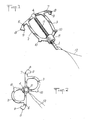
D'autres avantages et caractéristiques de l'invention seront mieux compris à la lecture de la description qui va suivre du dessin annexé dans lequel la figure unique représente en perspective un D.I.U. selon l'invention.Other advantages and characteristics of the invention will be better understood on reading the description which follows of the appended drawing in which the single figure represents in perspective a D.I.U. according to the invention.
Le D.I.U. conçu notamment en polyéthylène ou polypropylène comprend une tige 1 et deux bras latéraux représentés en 2 et 3 et formant chacun une boucle souple. Ces bras latéraux qui, avant insertion, sont symétriques par rapport à l'axe de la tige et situés dans un même plan vertical passant par ledit axe, sont chacun fixés solidairement par l'une de leurs extrémités à la partie supérieure 4 de la tige, et sont liés chacun par la seconde de leurs extrémités à une bague 5 susceptible de coulisser le long de la tige 1. La course maximale de la bague 5 est inférieure à la longueur totale de la tige (qui est ici avantageusement de l'ordre de 31,5 mm) .The D.I.U. designed in particular in polyethylene or polypropylene comprises a
Avant insertion, chaque bras latéral forme approximativement avec la tige du D.I.U. une courbe de type trapèze curviligne dont la grande base serait constituée par la tige. Le bras 2 est pourvu à sa partie supérieure et plus précisément au niveau du sommet supérieur de sa petite base, d'un prolongement latéral 6 légèrement replié sur lui-même, de même que le bras 3 est également pourvu d'un prolongement latéral 7 identique à celui du bras 2. Les prolongements 6 et 7 sont destinés à venir chacun en contact avec la paroi de la cavité utérine au voisinage de la lumière des trompes de Fallope. A cet effet chaque prolongement est muni à son extrêmité libre de deux aspérités arrondies 8 et 9, pour éviter toute déchirure ou lésion de ladite paroi.Before insertion, each lateral arm forms approximately with the IUD stem a curve of curvilinear trapezoid type, the large base of which is formed by the stem. The
Le sommet inférieur de la petite base de chaque bras latéral est également muni d'une aspérité arrondie 10 pour faciliter les contacts avec la paroi de la cavité utérine sans provoquer de lésions, d'une part, et conférer une certaine résistance mécanique à la boucle souple constituée par ledit bras latéral, d'autre part.The lower apex of the small base of each lateral arm is also provided with a
La tige du D.I.U est pourvue d'un enroulement métallique 11 conçu en cuivre (de préférence) ou en alliage de cuivre, notamment en laiton, pour bénéficier de l'effet contraceptif résultant du délitage du cuivre dans la cavité utérine. La surface de cuivre utile sera avantageusement de l'ordre de 250 mm2 à 400 mm2 pour assurer une protection efficace de l'ordre de trois à quatre ans. La tige est également liée , au voisinage de son extrêmité inférieure, à un fil chirurgical 12 devant être logé dans le col et suturé sur le rebord inférieur de ladite tige.The rod of the D.I.U is provided with a metal winding 11 designed in copper (preferably) or in a copper alloy, in particular brass, to benefit from the contraceptive effect resulting from the disintegration of copper in the uterine cavity. The useful copper surface will advantageously be of the order of 250 mm2 to 400 mm2 to ensure effective protection of the order of three to four years. The rod is also linked, in the vicinity of its lower end, to a
La figure unique représente également en pointillé la déformation des bras latéraux qui intervient quand la bague 5 coulisse le long de la tige 1 . Le mouvement de la bague 5 en translation de long de ladite tige modifie la conformation du D.I.U , le repoussant vers le fond de l'utérus en élargissant et en déformant sa structure et lui permettent de résister aux expulsions au niveau isthmique.The single figure also shows in dotted line the deformation of the lateral arms which occurs when the
Le D.I.U selon l'invention est inséré selon une méthode connue en soi au moyen d'un tube creux souple à l'extrêmité supérieure duquel est logée la tige, et dans lequel coulisse un organe pousseur. Le D.I.U selon l'invention est retiré facilement selon une technique classique quand une telle opération est nécessaire.The D.I.U according to the invention is inserted according to a method known per se by means of a flexible hollow tube at the upper end of which is housed the rod, and in which slides a pusher member. The D.I.U according to the invention is easily removed using a conventional technique when such an operation is necessary.
Les essais cliniques qui ont été entrepris pendant quinze mois sur 400 patientes toutes volontaires âgées de 18 à 35 ans, ont permis de mettre en évidence que le D.I.U. selon l'invention est bien toléré (aucune lésion, aucune expulsion spontanée, aucun retrait jugé nécessaire) et très fiable (aucune grossesse).The clinical trials which were undertaken for fifteen months on 400 patients all volunteers aged 18 to 35 years, made it possible to demonstrate that the D.I.U. according to the invention is well tolerated (no lesion, no spontaneous expulsion, no withdrawal deemed necessary) and very reliable (no pregnancy).
Claims (3)
Priority Applications (1)
| Application Number | Priority Date | Filing Date | Title |
|---|---|---|---|
| AT84400375T ATE31478T1 (en) | 1983-03-01 | 1984-02-24 | INTRAUTERINE CONTRACEPTIVE DEVICE. |
Applications Claiming Priority (2)
| Application Number | Priority Date | Filing Date | Title |
|---|---|---|---|
| FR8303358 | 1983-03-01 | ||
| FR8303358A FR2541891B1 (en) | 1983-03-01 | 1983-03-01 | INTRA-UTERINE CONTRACEPTIVE DEVICE |
Publications (2)
| Publication Number | Publication Date |
|---|---|
| EP0117818A1 true EP0117818A1 (en) | 1984-09-05 |
| EP0117818B1 EP0117818B1 (en) | 1987-12-23 |
Family
ID=9286393
Family Applications (1)
| Application Number | Title | Priority Date | Filing Date |
|---|---|---|---|
| EP84400375A Expired EP0117818B1 (en) | 1983-03-01 | 1984-02-24 | Intrauterine contraceptive device |
Country Status (5)
| Country | Link |
|---|---|
| EP (1) | EP0117818B1 (en) |
| AT (1) | ATE31478T1 (en) |
| DE (1) | DE3468167D1 (en) |
| ES (1) | ES286128Y (en) |
| FR (1) | FR2541891B1 (en) |
Cited By (7)
| Publication number | Priority date | Publication date | Assignee | Title |
|---|---|---|---|---|
| WO1986001709A1 (en) * | 1984-09-18 | 1986-03-27 | Strubel Bernd Jochen | Geometrically-variable intrauterine pessary and contraceptive device |
| US4676254A (en) * | 1985-03-16 | 1987-06-30 | Frohn Hermann Josef | Device for monitoring periods of ovulation |
| EP0305577A1 (en) * | 1987-09-03 | 1989-03-08 | Nauchno-Proizvodstvennoe Obiedinenie "Medinstrument" | Intrauterine contraceptive device |
| WO1990001310A1 (en) * | 1988-08-12 | 1990-02-22 | Jason Otto Gardosi | Intrauterine contraceptive device and forceps for removal |
| US20150051481A1 (en) * | 2008-04-02 | 2015-02-19 | Bayer Oy | Intrauterine system |
| IT201600107392A1 (en) * | 2016-10-25 | 2018-04-25 | Sergio Garau | INTRAUTERINE MEDICAL DEVICE |
| CN108030582A (en) * | 2018-01-15 | 2018-05-15 | 程默 | Intrauterine device |
Citations (3)
| Publication number | Priority date | Publication date | Assignee | Title |
|---|---|---|---|---|
| DE214172C (en) * | ||||
| US3405711A (en) * | 1966-07-22 | 1968-10-15 | Maurice I. Bakunin | Intrauterine contraceptive device |
| FR2427088A1 (en) * | 1978-05-30 | 1979-12-28 | Thouvenin Rene | Intra-uterine contraception device - has arms with top and bottom branches bearing against uterus wall |
-
1983
- 1983-03-01 FR FR8303358A patent/FR2541891B1/en not_active Expired
-
1984
- 1984-02-24 EP EP84400375A patent/EP0117818B1/en not_active Expired
- 1984-02-24 DE DE8484400375T patent/DE3468167D1/en not_active Expired
- 1984-02-24 AT AT84400375T patent/ATE31478T1/en active
- 1984-02-29 ES ES1984286128U patent/ES286128Y/en not_active Expired
Patent Citations (3)
| Publication number | Priority date | Publication date | Assignee | Title |
|---|---|---|---|---|
| DE214172C (en) * | ||||
| US3405711A (en) * | 1966-07-22 | 1968-10-15 | Maurice I. Bakunin | Intrauterine contraceptive device |
| FR2427088A1 (en) * | 1978-05-30 | 1979-12-28 | Thouvenin Rene | Intra-uterine contraception device - has arms with top and bottom branches bearing against uterus wall |
Cited By (8)
| Publication number | Priority date | Publication date | Assignee | Title |
|---|---|---|---|---|
| WO1986001709A1 (en) * | 1984-09-18 | 1986-03-27 | Strubel Bernd Jochen | Geometrically-variable intrauterine pessary and contraceptive device |
| US4676254A (en) * | 1985-03-16 | 1987-06-30 | Frohn Hermann Josef | Device for monitoring periods of ovulation |
| EP0305577A1 (en) * | 1987-09-03 | 1989-03-08 | Nauchno-Proizvodstvennoe Obiedinenie "Medinstrument" | Intrauterine contraceptive device |
| WO1990001310A1 (en) * | 1988-08-12 | 1990-02-22 | Jason Otto Gardosi | Intrauterine contraceptive device and forceps for removal |
| US20150051481A1 (en) * | 2008-04-02 | 2015-02-19 | Bayer Oy | Intrauterine system |
| IT201600107392A1 (en) * | 2016-10-25 | 2018-04-25 | Sergio Garau | INTRAUTERINE MEDICAL DEVICE |
| CN108030582A (en) * | 2018-01-15 | 2018-05-15 | 程默 | Intrauterine device |
| CN108030582B (en) * | 2018-01-15 | 2023-12-22 | 程默 | Contraceptive ring |
Also Published As
| Publication number | Publication date |
|---|---|
| FR2541891A1 (en) | 1984-09-07 |
| ES286128Y (en) | 1986-06-01 |
| ES286128U (en) | 1985-11-01 |
| DE3468167D1 (en) | 1988-02-04 |
| EP0117818B1 (en) | 1987-12-23 |
| ATE31478T1 (en) | 1988-01-15 |
| FR2541891B1 (en) | 1986-06-27 |
Similar Documents
| Publication | Publication Date | Title |
|---|---|---|
| EP1924218B1 (en) | Device for preventing female stress incontinence | |
| EP0117818B1 (en) | Intrauterine contraceptive device | |
| FR2736520A1 (en) | Stop to adjust length of cord of garment | |
| EP0191747A1 (en) | Contraceptive intra-uterine device and device for insertion and attachment to the uterine cavity wall | |
| EP0698381A1 (en) | Intraocular implant | |
| FR2771297A1 (en) | Bi-canicular probe, used to treat lacrimation | |
| FR2816454A1 (en) | Switches/button pusher wire conductor block connector having base body with vertical protrusions and hammer action swinging lever activating flexible section/wire insertion area. | |
| FR2700265A1 (en) | Meat plug for lacrimal pathology. | |
| FR2693652A1 (en) | Condom with manual applicator loop - comprises rubber sheath rolled around wire support loop, with end portions forming gripping handles for unrolling onto penis | |
| EP1476103A1 (en) | T-shaped intra-uterine device and method for the production thereof | |
| FR2536987A1 (en) | STERILET ENDO-UTERIN FOR ANIMALS SUCH AS DOGS | |
| FR2577163A1 (en) | Machine for automatically demoulding rubber articles which are closed at one end and open at the opposite end | |
| FR2554002A3 (en) | Device for extraction of the poison from stings and bites of insects or other animals | |
| WO2001068012A1 (en) | Device for inserting a t-shaped intra-uterine device | |
| FR2706125A1 (en) | Pacifier holder for newborns. | |
| EP0049660A1 (en) | Instrument for inserting an intra-uterine device, and assembly thereof | |
| EP0290307A1 (en) | Elastic sponge tampon, particularly a vaginal tampon | |
| FR2978753A1 (en) | Device for filling glass bottle with perfume, has sleeve whose lower part is laterally sealed against air, where opening is formed at end of lower part to allow outflow of liquid and inflow of air | |
| BE1005428A6 (en) | Bottle for product room. | |
| FR2633811A1 (en) | Button with rapid fastening and device for installing it | |
| EP0036805B1 (en) | Intra-uterine contraceptive device | |
| FR2651682A1 (en) | Apparatus for destroying varicose veins of the lower limbs in man | |
| FR2785524A1 (en) | Plastics socket for hip joint prosthesis has cup with spherical joint surface and necked cylindrical opening | |
| FR2529079A1 (en) | Endo uterine contraceptive - has arms with non injurious ends folding elastically above and below stem | |
| FR2613243A1 (en) | BRAKE FOR SKI WITH ARM TOTALLY FITTING ON THE SKI TRAY BY CLEAN ELASTICITY OF ITS STRUCTURE |
Legal Events
| Date | Code | Title | Description |
|---|---|---|---|
| PUAI | Public reference made under article 153(3) epc to a published international application that has entered the european phase |
Free format text: ORIGINAL CODE: 0009012 |
|
| AK | Designated contracting states |
Designated state(s): AT BE CH DE FR GB IT LI LU NL SE |
|
| RAP1 | Party data changed (applicant data changed or rights of an application transferred) |
Owner name: LABORATOIRE CENTRAL DE CHIMIOTHERAPIE ET DERMOCHIM |
|
| 17P | Request for examination filed |
Effective date: 19850130 |
|
| 17Q | First examination report despatched |
Effective date: 19860122 |
|
| R17C | First examination report despatched (corrected) |
Effective date: 19860904 |
|
| GRAA | (expected) grant |
Free format text: ORIGINAL CODE: 0009210 |
|
| AK | Designated contracting states |
Kind code of ref document: B1 Designated state(s): AT BE CH DE FR GB IT LI LU NL SE |
|
| REF | Corresponds to: |
Ref document number: 31478 Country of ref document: AT Date of ref document: 19880115 Kind code of ref document: T |
|
| ITF | It: translation for a ep patent filed |
Owner name: JACOBACCI & PERANI S.P.A. |
|
| REF | Corresponds to: |
Ref document number: 3468167 Country of ref document: DE Date of ref document: 19880204 |
|
| GBT | Gb: translation of ep patent filed (gb section 77(6)(a)/1977) | ||
| PLBE | No opposition filed within time limit |
Free format text: ORIGINAL CODE: 0009261 |
|
| STAA | Information on the status of an ep patent application or granted ep patent |
Free format text: STATUS: NO OPPOSITION FILED WITHIN TIME LIMIT |
|
| 26N | No opposition filed | ||
| PGFP | Annual fee paid to national office [announced via postgrant information from national office to epo] |
Ref country code: LU Payment date: 19930226 Year of fee payment: 10 Ref country code: CH Payment date: 19930226 Year of fee payment: 10 |
|
| ITTA | It: last paid annual fee | ||
| PGFP | Annual fee paid to national office [announced via postgrant information from national office to epo] |
Ref country code: NL Payment date: 19930228 Year of fee payment: 10 Ref country code: AT Payment date: 19930228 Year of fee payment: 10 |
|
| PGFP | Annual fee paid to national office [announced via postgrant information from national office to epo] |
Ref country code: SE Payment date: 19930301 Year of fee payment: 10 |
|
| PGFP | Annual fee paid to national office [announced via postgrant information from national office to epo] |
Ref country code: GB Payment date: 19930304 Year of fee payment: 10 |
|
| PGFP | Annual fee paid to national office [announced via postgrant information from national office to epo] |
Ref country code: BE Payment date: 19930309 Year of fee payment: 10 |
|
| EPTA | Lu: last paid annual fee | ||
| PG25 | Lapsed in a contracting state [announced via postgrant information from national office to epo] |
Ref country code: LU Free format text: LAPSE BECAUSE OF NON-PAYMENT OF DUE FEES Effective date: 19940224 Ref country code: GB Effective date: 19940224 Ref country code: AT Effective date: 19940224 |
|
| PG25 | Lapsed in a contracting state [announced via postgrant information from national office to epo] |
Ref country code: SE Effective date: 19940225 |
|
| PG25 | Lapsed in a contracting state [announced via postgrant information from national office to epo] |
Ref country code: LI Effective date: 19940228 Ref country code: CH Effective date: 19940228 Ref country code: BE Effective date: 19940228 |
|
| PGFP | Annual fee paid to national office [announced via postgrant information from national office to epo] |
Ref country code: DE Payment date: 19940428 Year of fee payment: 11 |
|
| BERE | Be: lapsed |
Owner name: LABORATOIRE CENTRAL DE CHIMIOTHERAPIE ET DERMOCHIM Effective date: 19940228 |
|
| PG25 | Lapsed in a contracting state [announced via postgrant information from national office to epo] |
Ref country code: NL Effective date: 19940901 |
|
| NLV4 | Nl: lapsed or anulled due to non-payment of the annual fee | ||
| GBPC | Gb: european patent ceased through non-payment of renewal fee |
Effective date: 19940224 |
|
| REG | Reference to a national code |
Ref country code: CH Ref legal event code: PL |
|
| EUG | Se: european patent has lapsed |
Ref document number: 84400375.6 Effective date: 19940910 |
|
| PG25 | Lapsed in a contracting state [announced via postgrant information from national office to epo] |
Ref country code: DE Effective date: 19951101 |
|
| PGFP | Annual fee paid to national office [announced via postgrant information from national office to epo] |
Ref country code: FR Payment date: 19980226 Year of fee payment: 15 |
|
| PG25 | Lapsed in a contracting state [announced via postgrant information from national office to epo] |
Ref country code: FR Free format text: LAPSE BECAUSE OF NON-PAYMENT OF DUE FEES Effective date: 19991029 |
|
| REG | Reference to a national code |
Ref country code: FR Ref legal event code: ST |