EP0115027A1 - Method for printing, evaluating and checking the printing image of a printer and device for carrying out this method - Google Patents
Method for printing, evaluating and checking the printing image of a printer and device for carrying out this method Download PDFInfo
- Publication number
- EP0115027A1 EP0115027A1 EP83112822A EP83112822A EP0115027A1 EP 0115027 A1 EP0115027 A1 EP 0115027A1 EP 83112822 A EP83112822 A EP 83112822A EP 83112822 A EP83112822 A EP 83112822A EP 0115027 A1 EP0115027 A1 EP 0115027A1
- Authority
- EP
- European Patent Office
- Prior art keywords
- printed
- line
- printing
- paper web
- Prior art date
- Legal status (The legal status is an assumption and is not a legal conclusion. Google has not performed a legal analysis and makes no representation as to the accuracy of the status listed.)
- Granted
Links
Images

Classifications
-
- B—PERFORMING OPERATIONS; TRANSPORTING
- B41—PRINTING; LINING MACHINES; TYPEWRITERS; STAMPS
- B41J—TYPEWRITERS; SELECTIVE PRINTING MECHANISMS, i.e. MECHANISMS PRINTING OTHERWISE THAN FROM A FORME; CORRECTION OF TYPOGRAPHICAL ERRORS
- B41J29/00—Details of, or accessories for, typewriters or selective printing mechanisms not otherwise provided for
- B41J29/38—Drives, motors, controls or automatic cut-off devices for the entire printing mechanism
- B41J29/393—Devices for controlling or analysing the entire machine ; Controlling or analysing mechanical parameters involving printing of test patterns
-
- G—PHYSICS
- G06—COMPUTING; CALCULATING OR COUNTING
- G06K—GRAPHICAL DATA READING; PRESENTATION OF DATA; RECORD CARRIERS; HANDLING RECORD CARRIERS
- G06K1/00—Methods or arrangements for marking the record carrier in digital fashion
- G06K1/12—Methods or arrangements for marking the record carrier in digital fashion otherwise than by punching
- G06K1/126—Methods or arrangements for marking the record carrier in digital fashion otherwise than by punching by photographic or thermographic registration
-
- G—PHYSICS
- G06—COMPUTING; CALCULATING OR COUNTING
- G06K—GRAPHICAL DATA READING; PRESENTATION OF DATA; RECORD CARRIERS; HANDLING RECORD CARRIERS
- G06K7/00—Methods or arrangements for sensing record carriers, e.g. for reading patterns
- G06K7/10—Methods or arrangements for sensing record carriers, e.g. for reading patterns by electromagnetic radiation, e.g. optical sensing; by corpuscular radiation
- G06K7/14—Methods or arrangements for sensing record carriers, e.g. for reading patterns by electromagnetic radiation, e.g. optical sensing; by corpuscular radiation using light without selection of wavelength, e.g. sensing reflected white light
-
- Y—GENERAL TAGGING OF NEW TECHNOLOGICAL DEVELOPMENTS; GENERAL TAGGING OF CROSS-SECTIONAL TECHNOLOGIES SPANNING OVER SEVERAL SECTIONS OF THE IPC; TECHNICAL SUBJECTS COVERED BY FORMER USPC CROSS-REFERENCE ART COLLECTIONS [XRACs] AND DIGESTS
- Y10—TECHNICAL SUBJECTS COVERED BY FORMER USPC
- Y10S—TECHNICAL SUBJECTS COVERED BY FORMER USPC CROSS-REFERENCE ART COLLECTIONS [XRACs] AND DIGESTS
- Y10S235/00—Registers
- Y10S235/90—Means to affix bar code, e.g. attaching, etching, coating, printing
Definitions
- a labeling device which is also a hand printer.
- a printing unit a known thermal printer for dot or line printing is used, with thermosensitive labels being applied to the carrier tape. This printer should also be used to print out barcodes.
- the method according to the invention has the salient advantage that printed images which contain incorrect information in relation to the correct information are immediately identified as "incorrect" and, for example, visually canceled.
- the operator who prints the labels or codes can therefore see immediately if a printed image does not provide the correct information.
- the rest of the printed image is blackened.
- a wide black crossbar is printed at the end of the print image and immediately afterwards. If the print image generated is a bar code, the black crossbar is wider than the widest code bar that occurs.
- the invention includes a novel printing method at all, which is the basis of the second alternative of patent claim 1 and patent claim 4.
- the thermal printing plate 16 can be embedded in the underside 15 of the carrier plate 1, so that the free underside 15 of the carrier plate, the thermal printing plate 16 and the lower surface of the plate-shaped cross part 2 form a plane.
Abstract
Description
Die Erfindung betrifft ein Verfahren zum Drucken, Aüswerten und überprüfen des Druckbildes eines elektrisch angesteuerten Druckers, insbesondere Thermodrucker für Strichcodes, wobei die zu druckenden Daten von Hand über eine Tastatur oder elektrisch aus einem Speicher dem Drucker eingegeben werden und die zu bedruckende Papierbahn mittels eines Motors durch den Drucker transportiert wird. Desweiteren betrifft die Erfindung eine Vorrichtung zur Durchführung des genannten Verfahrens.The invention relates to a method for printing, evaluating and checking the print image of an electrically controlled printer, in particular a thermal printer for bar codes, the data to be printed being entered by hand via a keyboard or electrically from a memory into the printer and the paper web to be printed on by means of a motor is transported through the printer. Furthermore, the invention relates to a device for performing the method mentioned.
Es sind eine Reihe von Verfahren zum Drucken von Etiketten und zum gleichzeitigen Etikettieren bekannt geworden, bei denen der Druck- und Etikettiervorgang mittels eines Handgerätes erfolgt. Durch die DE-OS 32 o9 o53 ist ein Verfahren bekannt geworden, bei dem durch eine von Hand bedienbare Betätigungsvorrichtung während aufeinanderfolgender Arbeitszyklen diese betätigbar ist, wobei in jedem Zyklus ein Druckkopf ein Etikett bedruckt, das bedruckte Etikett abgelöst und in eine Etikettenaufbringstellung in Bezug auf eine Etikettenaufbringwalze gebracht wird, danach Farbe auf den Druckkopf in.jedem Zyklus aufgebracht wird und anschließend das Druckbild auf das Etikett aufgedruckt und das bedruckte Etikett weitertransportiert wird. Dabei wird der Betrieb des Handetikettiergerätes über eine vorbestimmte Anzahl von Arbeitszyklen hinaus behindert.A number of methods for printing labels and for simultaneous labeling have become known, in which the printing and labeling process takes place by means of a hand-held device. From DE-OS 32 o9 o53 a method has become known in which it can be actuated by a manually operated actuating device during successive working cycles, a print head printing a label in each cycle, the printed label being detached and in a label application position with respect to a label applicator roller is applied, then ink is applied to the print head in each cycle, and then the printed image is printed on the label and the printed label is transported on. The operation of the hand labeling device is hindered beyond a predetermined number of working cycles.
Die dazu benötigten Etikettiergeräte, für die dasjenige dieser Offenlegungsschrift 32 o9 o53 stellvertretend genannt ist, bestehen grundsätzlich aus gewöhnlichen Druckwerken, die in der Regel Typenräder aufweisen, die die einzelnen Drucktypen tragen. Der Druck erfolgt über Druckwalzen mit Farbaufgabe.The labeling devices required for this, for which that of this laid-
Auf diese Weise lassen sich auch Strichcodes auf Selbstklebe-Etiketten drucken; die DE-OS 31 17 231 beinhaltet ein Druckwerk zum Drucken von Strichcodes auf Selbstklebe-Etiketten, die auf einem Trägerband haften. Das Druckwerk enthält ein Druckrad, auf dem mehrere, um eine gemeinsame Achse relativ zueinander verdrehbare Typenringe sitzen. Das Trägerband mit den daran haftenden Selbstklebe-Etiketten wird mit Hilfe einer Druckrolle gegen das Druckrad gedrückt. Damit die zu druckenden Strichcodes mit Hilfe elektro-optischer Lesegeräte fehlerfrei abgelesen werden können, sind an die Druckqualität der Strichcodes hinsichtlich der Gleichmäßigkeit und des Kontaktes hohe Anforderungen zu stellen. Zur Erfüllung dieser Anforderungen weisen die Typenringe eine kreiszylindrische Umfangsfläche auf, an der Strichcode-Typen aus elastischem Material gebildet sind, mit denen eine Einfärbe-Vorrichtung in Kontakt steht. Die Druckrolle ist um eine parallel zur Achse der Typenringe verlaufende Achse drehbar und besteht aus nicht elastischem Material.In this way, barcodes can also be printed on self-adhesive labels; DE-OS 31 17 231 includes a printing unit for printing bar codes on self-adhesive labels that adhere to a carrier tape. The printing unit contains a printing wheel on which several type rings are seated which can be rotated relative to one another about a common axis. The carrier tape with the self-adhesive labels attached to it is pressed against the printing wheel with the help of a pressure roller. So that the bar codes to be printed can be read without errors using electro-optical readers, high demands must be placed on the print quality of the bar codes with regard to uniformity and contact. To meet these requirements, the type rings have a circular-cylindrical circumferential surface on which bar code types made of elastic material are formed, with which a coloring device is in contact. The pressure roller can be rotated about an axis running parallel to the axis of the type rings and is made of non-elastic material.
Durch die DE-OS 28 16 161 ist ein Etikettiergerät bekannt geworden, welches ebenfalls ein Handdrucker ist. Als Druckwerk wird ein ansich bekannter Thermodrucker für punkt- /oder strichweisen Druck verwendet, wobei auf dem Trägerband thermosensitive Etiketten aufgebracht sind. Dabei soll dieser Drucker auch zum Ausdrucken von Strichcodes verwendet werden.From DE-OS 28 16 161 a labeling device has become known, which is also a hand printer. As a printing unit, a known thermal printer for dot or line printing is used, with thermosensitive labels being applied to the carrier tape. This printer should also be used to print out barcodes.
Wichtig bei der Verwendung eines Thermodruckers ist, daß der einzelne Transportschritt zum Transport der Papiers durch den Drucker der Punktzeilenteilung oder Punktrasterteilung des einzelnen Resistorpunktes entspricht, so daß die Größe des Transportschrittes gleich der Länge des einzelnen Resistorpunktes oder ein Vielfaches davon ist.It is important when using a thermal printer that the individual transport step for transporting the paper through the printer corresponds to the dot line division or dot pitch division of the individual resistor point, so that the size of the transport step is equal to or a multiple of the length of the individual resistor point.
Die bekannten Verfahren und Vorrichtungen besitzen jedoch eine Reihe von Nachteilen. Mit den herkömmlichen Druckwerken, die mit Typenringen und Druckfarbe arbeiten, ist es in Handgeräten aufgrund der notwendigen Kleinheit und Mobilität sehr schwer, exakt gedruckte Strichcodes zu erzeugen, die einwandfrei von optischen Leseeinrichtungen lesbar sind. Deshalb besitzen auch nur stationäre Geräte gleichzeitig Einrichtungen zum Lesen eines gedruckten Codes. Gerade aber die überprüfung des eben gedruckten Druckbildes ist von entscheidender Wichtigkeit, um Fehlerquellen, wie Fehletikettierungen, auszuschalten. Ebenso ist es ein unbedingtes Erfordernis, daß eine derartige Oberprüfung selbstätig erfolgt und dem Personal nur die Fehlerhaftigkeit eines eben gedrucken Etiketts oder Codes angezeigt wird. Der Druckvorgang und die überprüfung des soeben gedruckten Druckbildes müssen deshalb so einfach wie möglich gestaltet werden, damit auch das Verkaufspersonal damit umgehen kann. Diesen Forderungen genügen die bekannten Vorrichtungen und Verfahren des Standes der Technik nicht.However, the known methods and devices have a number of disadvantages. With the conventional printing units, which work with type rings and printing ink, it is very difficult in handheld devices, because of the small size and mobility, to produce precisely printed bar codes that are perfectly readable by optical reading devices. That is why only stationary devices have devices for reading a printed code at the same time. But it is precisely the checking of the printed image that has just been printed that is of crucial importance in order to eliminate sources of error, such as incorrect labeling. It is also an absolute requirement that such a top-level check is carried out automatically and that the staff is only shown the defectiveness of a label or code that has just been printed. The printing process and the review of the printed image that has just been printed must therefore be made as simple as possible so that the sales staff can also handle it. The known devices and methods of the prior art do not meet these requirements.
Der Erfindung liegt deshalb die Aufgabe zugrunde, ein Verfahren und eine Vorrichtung der eingangs genannten Gattung zu schaffen, bei dem das soeben generierte Druckbild überprüft und bei falschem Ausdruck oder falscher Obermittlung dieses Druckbild ausgesondert wird und das richtige Druckbild später beliebig gelesen werden kann.The invention is therefore based on the object of providing a method and a device of the type mentioned at the outset in which the print image just generated is checked and, in the event of incorrect printout or incorrect transmission, this print image is discarded and the correct print image can be read at will later.
Das Verfahren ist erfindungsgemäß durch den Patentanspruch 1 gekennzeichnet.The method is characterized by
Weitere vorteilhafte Ausgestaltungen des erfindungsgemäßen Verfahrens sind in den Unteransprüchen 2 bis y gekennzeichnet. Das erfindungsgemäße Verfahren besitzt den hervorstechenden Vorteil, daß mit ihm Druckbilder, die gegenüber den richtigen Informationen eine falsche Information beinhalten, sofort als "falsch" gekennzeichnet und beispielsweise optisch sichtbar entwertet werden. Die Bedienungsperson, die die Etiketten oder Codes ausdruckt, sieht deshalb sofort, wenn ein Druckbild nicht die richtige Information wiedergibt. Beispielsweise wird in diesem Fall der Rest des Druckbildes geschwärzt. Oder es wird am Ende des Druckbildes und unmittelbar anschließend ein breiter schwarzer Querbalken gedruckt. Ist das erzeugte Druckbild ein Strichcode, so ist der schwarze Querbalken breiter als der breiteste auftretende Code-Balken.Further advantageous embodiments of the method according to the invention are characterized in
Das Druckbild kann aber auch schon bei anderen Fehlern, als der Wiedergabe von falschen Informationen als ungültig gekennzeichnet werden. Beispielsweise dann, wenn die Reflexion des einzelnen Zeichens bzw. des Strichcodes unzureichend ist und unter einen vorgegebenen Wert fällt. In diesem Falle wird das Druckbild als nicht verwendbar gekennzeichnet, wenn der Code nicht genügend ausgedruckt oder zu schwach gedruckt ist. In vorteilhafter Weise kann desweiteren das Druckbild als unbrauchbar gekennzeichnet werden, wenn der Obergang zwischen dem gedruckten Zeichen bzw. den gedruckten Strichen und den daneben befindlichen druckfreien Leerstellen nicht genügend scharf ist und unter einen bestimmten Wert gefallen ist. Das Druckbild wird somit auch dann als unbrauchbar gekennzeichnet, wenn die Ränder der Zeichen unscharf oder verwischt sind.However, the print image can also be marked as invalid in the case of errors other than the reproduction of incorrect information. For example, when the reflection of the individual character or the bar code is insufficient and falls below a predetermined value. In this case, the print image is marked as unusable if the code is not printed out enough or is printed too weakly. Advantageously, the printed image can furthermore be marked as unusable if the transition between the printed characters or the printed lines and the print-free spaces next to them is not sufficiently sharp and has fallen below a certain value. The printed image is therefore marked as unusable even if the edges of the characters are blurred or blurred.
In vorteilhafter Weise sieht somit die Bedienungsperson der erfindungsgemäßen Vorrichtung sofort, wenn ein Etikett oder ein Druckbild nicht verwendbar ist, weil in diesem Fall das Etikett oder das Druckbild als unbrauchbar gekennzeichnet ist. Die Bedienungsperson kann somit dieses als unbrauchbar gekennzeichnete Etikett oder Druckbild sofort ausscheiden.In an advantageous manner, the operator of the device according to the invention thus immediately sees when a label or a printed image cannot be used, because in this case the label or the printed image is marked as unusable. The operator can thus immediately remove this label or printed image that is marked as unusable.
In vorteilhafter Weise kann das erfindungsgemäße Verfahren sowohl bei Handgeräten, als auch bei stationären Geräten eingesetzt werden. Insbesondere ist der Einsatz des erfindungsgemäßen Verfahrens für Handdruckgeräte vorteilhaft, mit denen die Waren vorort ausgezeichnet werden können.The method according to the invention can advantageously be used both in hand-held devices and in stationary devices. In particular, the use of the method according to the invention is advantageous for hand pressure devices with which the goods can be labeled on site.
Eine Vorrichtung zur Durchführung des erfindungsgemäßen Verfahrens ist durch den Anspruch 8 gekennzeichnet. Weitere erfindungsgemäße Ausgestaltungen der Vorrichtung sind in den Ansprüchen 9 bis 14 gekennzeichnet.A device for performing the method according to the invention is characterized by
Die erfindungsgemäße Vorrichtung besitzt den Vorteil, daß sie zum ersten mal in einem Geräte, insbesondere in einem Handgerät, eine Druckeinrichtung und eine Prüfeinrichtung für das gedruckte Druckbild vereinigt. Darüberhinaus kann der Kunde in das Gerät von außen ein kundenspezifisches Steuer-und Rechnerprogramm einsetzen. Daneben besitzt die erfindungsgemäße Vorrichtung neben einer visuellen Anzeige und einer Festprogrammier-Einrichtung eine alpha-nummerische Tastatur zur Eingabe beliebiger Daten direkt vor Ort. Mit der Festprogrammier-Einrichtung können beispielsweise verschiedene Währungen, eingestellt werden. Daneben ist die erfindungsgemäße Vorrichtung klein, robust und mechanisch unanfällig.The device according to the invention has the advantage that it combines for the first time in one device, in particular in a hand-held device, a printing device and a testing device for the printed printed image. In addition, the customer can insert a customer-specific control and computer program into the device from the outside. In addition to a visual display and a fixed programming device, the device according to the invention also has an alpha-numeric keyboard for entering any data directly on site. With the fixed programming device, for example, different currencies can be set. In addition, the device according to the invention is small, robust and mechanically insensitive.
Mit dem erfindungsgemäßen Verfahren und der dazugehörigen Vorrichtung können somit zum ersten Mal Druckbilder erzeugt werden, die noch während ihrer Entstehung überprüft werden und bei einem Fehler sofort und vor Beendigung des Druckvorganges oder unmittelbar danach als entwertet optisch sichtbar gekennzeichnet werden.With the method according to the invention and the associated device, print images can thus be generated for the first time, which are checked while they are still being created and, in the event of an error, are marked as devalued immediately and immediately before the printing process has ended or immediately thereafter.
Desweiteren können auf dem Papier befindliche Passermarken vorhanden sein zur Positionierung der aufeinanderfolgenden Druckbilder. Durch dieser Passermarken kann in vorteilhafter Weise die Vorschubgeschwindigkeit des das Papier transportierenden Motors und der Druckbeginn für das einzelne Druckbild gesteuert werden.Furthermore, registration marks located on the paper can be present for positioning the successive print images. Through this registration marks can in the feed speed of the motor transporting the paper and the start of printing for the individual printed image are advantageously controlled.
Desweiteren beinhaltet die Erfindung ein neuartiges Druckverfahren überhaupt, welches der zweiten Alternative des Patentanspruchs 1 und dem Patentanspruch 4 zugrunde liegt.Furthermore, the invention includes a novel printing method at all, which is the basis of the second alternative of
Durch dieses Verfahren wird das Druckbild fortlaufend generiert. Ist beispielsweise das Druckbild ein Strich-Code, so werden die einzelnen Strichbalken quer zur Längsachse der Papierbahn gedruckt. In diesem Fall drucken alle Resistoren der Thermodruckplatine parallel, es entsteht der schmalste Strichbalken der Breite der Höhe des einzelnen Resistordruckpunktes. Deshalb muß die druckende Länge des einzelnen Resistordruckpunktes der kleinsten Strichstärke des zu druckenden Codes entsprechen. Die Breite eines dickeren Codestrichs entspricht dann immer einem Vielfachen der Höhe des einzelnen Resistordruckpunktes. Deshalb muß hier auch eine höchst exakte Antriebstechnik gewährleistet sein. Denn die Antriebstechnik muß jeweils in der Lage sein, die Papierbahn um genau das Vielfache der Strichstärke des dünnsten Codebalkens zu transportieren.This process generates the print image continuously. If, for example, the print image is a bar code, the individual line bars are printed across the longitudinal axis of the paper web. In this case, all the resistors on the thermal printing board print in parallel, creating the narrowest bar of the width of the height of the individual resistor printing point. Therefore, the printing length of the individual resistor printing point must correspond to the smallest line width of the code to be printed. The width of a thicker code line then always corresponds to a multiple of the height of the individual resistor pressure point. Therefore, a very precise drive technology must be guaranteed here. Because the drive technology must be able to transport the paper web by exactly the multiple of the line width of the thinnest code bar.
Bei diesem Druckverfahren drucken somit immer alle Druckpunkte des Druckers gleichzeitig. Dieses Verfahren läßt sich auch mit beliebigen anderen Druckwerken, beispielsweise den herkömmlichen des Standes der Technik, bewerkstelligen, wenn diese exakt genug drucken und einen exakten Papiervorschub um ein Vielfaches der Länge des einzelnen Druckzeichens gewährleisten. Jedoch läßt sich dieses Druckverfahren besonders elegant bei Verwendung einer Thermodruckplatine anwenden.With this printing method, all printing points of the printer therefore always print at the same time. This method can also be carried out with any other printing units, for example the conventional ones of the prior art, if they print precisely enough and guarantee an exact paper feed by a multiple of the length of the individual printing characters. However, this printing method can be used particularly elegantly when using a thermal printing board.
Der Vorteil dieses Druckverfahrens, bei dem die Information längs zur Papierbahn gedruckt und später auch wiederum längs zur Papierbahn gelesen wird, besitzt gegenüber dem bekannten Druckverfahren, bei dem die Information quer zur Papierbahn gedruckt und später auch wiederum quer zur Papierbahn gelesen wird, den Vorteil, daß mit diesem ein beliebig langes Druckbild und somit eine beliebige Informationsmenge gedruckt werden kann. Im Falle des herkömmlichen Verfahrens ist ja die Länge des Druckbildes durch die Breite der Papierbahn gegeben, wobei ja die Breite des Druckbildes, also in Längsausdehnung der Papierbahn, keine zusätzliche Information gegenüber der ersten Druckzeile beinhaltet. Die Breite des Druckbildes wird somit nur durch die nachfolgende Lesbarkeit des Druckbildes bestimmt.The advantage of this printing process, in which the information is printed along the paper web and later read again along the paper web, has the advantage over the known printing process, in which the information is printed across the paper web and later also read across the paper web, that an arbitrarily long print image and thus any amount of information can be printed with it. In the case of the conventional method, the length of the print image is given by the width of the paper web, the width of the print image, that is to say in the longitudinal extent of the paper web, not containing any additional information with respect to the first print line. The width of the printed image is therefore only determined by the subsequent readability of the printed image.
Beim Prüfen eines längs der Papierbahn gedruckten Druckbildes gemäß dem erfindungsgemäßen Verfahren fährt der Sensor am Anfang, beispielsweise gesteuert durch eine Passermarke auf dem Papier, ein Stück in die Druckzeile hinein und wird dort angehalten. Nunmehr laufen die Druckzeichen fortlaufend mit dem Papiervorschub am Sensor vorbei, der somit mit der Geschwindigkeit der Papierbahn das Druckbild liest und somit die Prüfung des Druckbildes erst nach dessen Fertigstellung abschließen kann. In diesem Fall wird deshalb zur Kennzeichnung, daß das Druckbild. unbrauchbar ist, unmittelbar anschließend an das Druckbild eine Entwertung gedruckt, beispielsweise ein schwarzer Querbalken, der dicker ist, als der dickste verwendete Codestrich.When checking a print image printed along the paper web according to the method according to the invention, the sensor initially moves a piece into the print line, for example controlled by a registration mark on the paper, and is stopped there. Now the printed characters run continuously with the paper feed past the sensor, which thus reads the printed image at the speed of the paper web and thus can only complete the inspection of the printed image after its completion. In this case, it is therefore used to identify that the printed image. is unusable, a cancellation is printed immediately after the printed image, for example a black cross bar that is thicker than the thickest code line used.
Beispiele der Erfindung sind in der Zeichnung dargestellt und anschließend beschrieben. Dabei zeigen:
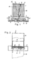
Figur 1 eine Draufsicht auf eine erfindungsgemäße Vorrichtung zur Durchführung des erfindungsgemäßen Verfahrens unter Weglassung der Deckplatte und des AntriebsmotorsFigur 2 eine Draufsicht auf dieUnterseite von Figur 1- Figur 3 eine Ansicht von hinten auf die Querseite der Trägerplatte
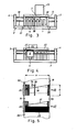
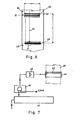
Figur 4 eine Ansicht von vorn auf die Längsseite des Querteils mit Führungsstangen, Schlitten und opto-elektronischem SensorFigur 5 das Druckbild auf einem Papierstreifen, gedruckt nach der ersten Alternative desPatentanspruchs 1, wobei der obere Teil einen als "richtig" abgetasteten Strichcode aufweist und der untere Teil als "falsch" abgetasteten Strichcode, desssen unterer Teil deshalb geschwärzt ist, umfaßtFigur 6 das Druckbild auf einem Papierstreifen, welches gemäß der zweiten Alternative desPatentanspruchs 1 längs zum Papierstreifen gedruckt ist, wobei das Druckbild in Längsausdehnung des Papierstreifens beliebig lang sein kannFigur 7 ein Blockschaltbild mit einem Drucker zum Drucken eines Druckbildes gemäß Figur 6, um die Ansteuerung der Thermodruckplatine zu zeigenFigur 8 eine Thermodruckplatine mit durchgehendem Resistorbalken und integrierten elektronischen Bausteinen, wie sie inFigur 7 Verwendung finden und kann undFigur 9 eine Ansicht der Vorrichtung, welche hier als Handgerät ausgeführt ist.
- Figure 1 is a plan view of an inventive device for performing the method according to the invention with the omission of the cover plate and the drive motor
- FIG. 2 shows a top view of the underside of FIG. 1
- Figure 3 is a rear view of the transverse side of the support plate
- Figure 4 is a front view of the long side of the cross member with guide rods, slide and opto-electronic sensor
- Figure 5 shows the printed image on a paper strip, printed according to the first alternative of
claim 1, the upper part comprising a bar code scanned as "correct" and the lower part comprising a bar code scanned as "wrong", the lower part of which is therefore blackened - Figure 6 shows the print image on a paper strip, which is printed along the paper strip according to the second alternative of
claim 1, wherein the print image can be of any length in the longitudinal extension of the paper strip - Figure 7 is a block diagram with a printer for printing a print image according to Figure 6 to show the control of the thermal printing board
- FIG. 8 shows a thermal printing board with a continuous resistor bar and integrated electronic components, as can be found and used in FIG. 7, and
- Figure 9 is a view of the device, which is designed here as a hand-held device.
In der folgenden Beschreibung bedeutet Druckzeile oder Zeile jeweils diejenige Zeichengenerierung, die die Typendruckzeile des Druckers erzeugt. Bei Verwendung einer Thermodruckplatine ist das die Resistorzeile derselben.In the following description, print line or line means the character generation that generates the type print line of the printer. When using a thermal print board, this is the resistor row of the same.
Die erfindungsgemäße Vorrichtung besteht gemäß Figur 1 aus einer Trägerplatte 1, die vorzugsweise flach und länglich ist. An diese Trägerplatte 1 ist ein plattenförmiges Querteil einstückig angeformt, wobei die Trägerplatte und das Querteil den Grundkörper bilden. Das plattenförmige Querteil ist in seiner Längsausdehnung zur Querausdehnung der Trägerplatte angebracht, so daß die Enden des Querteils 2 die Trägerplatte 1 überragen. An den Enden des plattenförmigen Querteils 2 sind zwei Seitenteile 3, 4 montiert, zwischen denen zwei Führungsstangen 5 und 19 (Figur 3) angeordnet sind. Wie aus Figur 3 ersichtlich ist, befinden sich die Fuhrungsstangen in verschiedener Höhe. Auf der äußeren Führungsstange 5 ist ein Schlitten 6 angeordnet, der gleitbar auf der Führungsstange 5 hin- und herbeweglich ist. An dem Schlitten 6 ist ein Führungsarm 7 beweglich angelenkt, wobei dieser Führungsarm 7 ein gebogenes Endteil 8 besitzt, welches mit seinem äußeren Ende gelenkig und verschiebbar im Drehpunkt lo des Schlittens 6 befestigt ist. Das andere Ende des Hebelarms 7 ist drehbar um eine Achse 9 auf der Trägerplatte 1 gehaltert. Diese Achse 9 ragt beispielsweise in eine Lagerbuchse 38 (Figur 3) hinein. Beim Schwenken des Hebels 7 um die Drehachse 9 bewegt sich somit der Schlitten 6 auf der Führungsstange 5 hin-und her.According to FIG. 1, the device according to the invention consists of a
Im plattenförmigen Querteil 2 ist längs zur Längsachse desselben ein Längsschlitz 12 angeordnet, der beispielsweise von einer umlaufenden Vertiefung 13 umgeben sein kann. Der Schlitten 6 trägt einen opto-elektronischen Sensor, der beispielsweise ein integrierter Infrarot-Sender und Infrarot-Empfänger ist. Sämtliche Zuleitungen zu diesem Sensor 11 sind weggelassen.In the plate-shaped cross part 2 a
Die Trägerplatte trägt auf ihrer Oberseite zwei ihren Längsrändern benachbarte Seitenteile 20, 21, die sich bis zum plattenförmigen Querteil erstrecken (Figur 1). Auf diesen Seitenteilen 20, 21 der Trägerplatte 1 ist eine Deckplatte 22 (Figur 3) montiert, auf der wiederum ein Elektro-Motor 23 und ein nicht gezeigtes Zahnradgetriebe oder -vorgelege montiert ist.Die Antriebswelle des Motors 23 steht über das Zahnradgetriebe mit dem Hebelarm 7 in Verbindung, wobei auf den Hebelarm ein (nicht gezeigtes) Antriebszahnrad montiert ist. Wird der Elektro-Motor 23 in Tätigkeit gesetzt, so wird über das Zahnradgetriebe der Hebelarm 7 geschwenkt, so daß der Schlitten 6 und mit ihm der opto-elektronische Sensor 11 genau über den Schlitz 12 innerhalb des Querteils 2 entlang läuft.On its upper side, the carrier plate carries two
Auf der Unterseite 15 der Trägerplatte 1 ist desweiteren eine Thermodruckplatine 16 montiert, wobei die Druckzeile 33 der Thermodruckplatine 16, also die druckende Resistor-Zeile, bestehend aus den einzelnen Resistor-Druckpunkten 17, von der Oberfläche 15 der Trägerplatte 1 abgewandt ist, so wie es in Figur 2 gezeigt ist. Die Resistor-Druckzeile 33 der Thermodruckplatine 16 ist dabei in unmittelbarer Nachbarschaft des Längsschlitzes 12 angeordnet, wobei der Längsschlitz 12 länger als die Druckzeile 33 ist.On the
Desweiteren kann die Thermodruckplatine 16 in die Unterseite 15 der Trägerplatte 1 eingelassen sein, so daß die freie Unterseite 15 der Trägerplatte, die Thermodruckplatine 16 und die untere Oberfläche des plattenförmigen Querteils 2 eine Ebene bilden.Furthermore, the
Desweiteren besteht die Vorrichtung aus einer nicht gezeigten Transporteinrichtung für eine Papierbahn 18, die über die Unterseite 15 der Trägerplatte 1 und die Thermodruckplatine 16 und somit über die Druckzeile 32 der einzelnen Resistoren 17 hinwegläuft. Eine ebenfalls nicht gezeigte Andrückeinrichtung drückt die Papierbahn 18 im Bereich der Druckzeile 33 der Thermodruckplatine 16 an diese Druckzeile an. Desweiteren besitzt die Transporteinrichtung zum Transport der Papierbahn 18 durch den Drucker einen Motor, der ebenfalls nicht gezeigt ist. Aufgrund der beschriebenen Teile wird somit die Papierbahn 18 beim Drucken dergestalt bedruckt, daß das Druckbild auf der Papierbahn 18 auf der der unteren Oberfläche des Querteils 2 zugewandten Seite der Papierbahn 18 aufgedruckt ist, so daß das Druckbild bei Draufsicht auf Figur 1 innerhalb des Längsschlitzes 12 sichtbar erscheint.Furthermore, the device consists of a transport device, not shown, for a
Diese Druckbild kann nun mittels des opto-elektronischen Sensors 11 innerhalb des Längsschlitzes 12 gelesen werden, wenn der Schlitten 6 mitsamt dem Sensor 11 längs des Schlitzes 12 bewegt wird.This print image can now be read by means of the opto-
Zur Verbesserung der Führung kann zusätzlich die zweite Führungsstange 19 verwendet werden, wobei am.Schlitten 6 dazu ein Hebelarm 24 angeordnet ist, der die Führungsstange 19 umgreift. Dadurch kann der Schlitten 6 längs der Führungsstange 5 mit hoher Geschwindigkeit verfahren werden.To improve the guidance, the
Desweiteren kann die Trägerplatte 1 auf der Oberseite gemäß den Figuren 1, 3 und 4 Kühlrippen 14 aufweisen, die zur Wärmeabfuhr der beim Drucken erzeugten Wärme dienen. Diese Kühlrippen 14 sind längs der Seitenteile 2o, 21 der Trägerplatte 1 angeordnet, wobei der Hebelarm 7 zwischen der Deckplatte 22 und dem oberen Ende der Kühlrippen 14 frei beweglich sich befindet. Damit ist auch ein mechanischer Schutz des Hebelarms innerhalb des Gehäuses, gebildet aus Trägerplatte, den Seitenteilen 2o, 21 und der Deckplatte 22 gewährleistet. Der Grundkörper, bestehend aus Trägerplatte und Querteil, besteht vorzugsweise aus Metall, wobei der Grundkörper einschließlich der Kühlrippen 14 einstückig aus einem Block gefräst sein kann.Furthermore, the
Figur 5 dient zur Erläuterung des erfindungsgemäßen Verfahrens, welches mit der oben beschriebenen Vorrichtung durchgeführt werden kann.FIG. 5 serves to explain the method according to the invention, which can be carried out with the device described above.
Zur Durchführung des erfindungsgemäßen Verfahrens wird die Papierbahn 18 mittels der nicht gezeigten Transporteinrichtung einschließlich des dazugehörigen Motors über die Unterseite 15 der Trägerplatte 1 und die Oberseite 16 der Thermodruckplatine und über die Druckzeile 33, die einzelnen Resistor-Druckpunkte lß transportiert. Dabei wird die Papierbahn 18 im Bereich der Resistoren 17 mittels einer ebenfalls nicht gezeigten Gegendruckvorrichtung angedrückt. Werden nun eine Reihe von Resistoren beheizt, so verfärbt sich an diesen Stellen das Papier, welches thermosensitiv ist. Dabei darf der maximale Vorschub der Papierbahn 18 durch den Drucker nur der Länge des einzelnen Resistordruckpunktes 17 entsprechen, weshalb der Antriebsmotor für die Vorschubeinrichtung der Papierbahn 18 in vorteilhafter Weise ein Schrittmotor sein kann.To carry out the method according to the invention, the
Das Druckbild wird nun dergestalt erzeugt, daß jeweils Druckzeilen-weise die Resistoren 17 der Druckzeile 33 beheizt werden und das Druckbild von oben nach unten zeilenweise quer zur Papierbahn gedruckt wird. Dabei ist es nicht notwendig, daß alle Resistoren, die in einer Zeile drucken sollen, auch gleichzeitig und somit parallel angesteuert werden. Untenentsprechender Steuerung des Schrittschaltmotors - beispielsweise Einschaltung von Pausen - kann eine Druckzeile auch dergestalt gedruckt werden, daß zuerst beispielsweise ein Drittel der den Druck ausführenden Resistoren pro Zeile angesteuert wird, danach das zweite Drittel der den Druck ausführenden Resistoren und danach das letzte Drittel. Eine derartige Steuerung kann beim Auftreten extremer Wärmebedingungen oder extrem langer gleichbleibender Druckbilder von Vorteil sein. Bei dem gegebenen Beispiel muß dann natürlich der Schrittschaltmotor zur Förderung der Papierbahn zwischen einem Schaltschritt zwei Schritte aussetzen, bis die gesamte Zeile gedruckt ist. Auf diese Weise wird somit fortquer/ laufend von oben nach unten das Druckbild gedruckt, beispielsweise ein Code.The print image is now generated in such a way that the resistors 17 of the
In Figur 5 ist als Druckbild 25 ein Code abgebildet. Das Druckbild 25 besteht somit aus längsverlaufenden Codebalken, die zeilenweise aus einer Vielzahl von n-Zeilen 26 zusammengesetzt sind. Somit besteht jeder in Figur 5 schwarze Längsbalken des Druckbildes 25 aus einer Vielzahl von einzelnen Druckzeichen 34, deren Länge multipliziert mit der Anzahl n der Zeilen die Länge des Druckbildes ergeben.A code is shown in FIG. 5 as printed
Nachdem nunmehr die erste oder die ersten Zeilen 26 des Druckbildes 25 gedruckt sind, erscheint dieses begonnene Druckbild 25 aufgrund des Transportes der Papierbahn 18 sichtbar im Längsschlitz 12. Falls es sich um einen Code-Druck handelt, steht ja schon mit Fertigstellung der ersten Druckzeile fest, ob das Druckbild richtig oder falsch wird, da ja die Druckinformation der ersten Zeile'nur n-fach wiederholt wird. Wenn somit das begonnene Druckbild 25 den Längsschlitz 12 passiert, so wird der Schlitten 6 mitsamt dem opto-elektronischen Sensor 11 über das begonnene Druckbild hinwegbewegt und dabei die gedruckte Information optisch gelesen. Dazu kann der Sensor 11 ein integrierter Infrarot-Sender-Empfänger mit Fokussierung sein.Now that the first or the
Das vom Druckbild zum Sensor 11 reflektierte Signal kann nun auf mehrfache Weise ausgewertet werden. Zum einen kann die Druckinformation auf sachliche Richtigkeit überprüft werden, ob somit das generierte, begonnene Druckbild tatsächlich mit der eingegebenen Information, herrührend entweder aus einer Handeingabe, aus einem Speicher oder einem Rechner, übereinstimmt. Desweiteren kann das Reflektionsvermögen des einzelnen gedruckten Zeichens gemessen werden und somit beispielsweise die Schwärze des einzelnen Druckzeichens. Darüberhinaus kann zusätzlich das Differential der Refektion ermittelt werden, um den übergang zwischen einem gedruckten Zeichen 34 und einer unbedruckten Leerstelle 35 zu ermitteln. Beispielsweise können die beiden letztgenannten Messungen, also die Reflektion des Druckbildes und das Differential der Reflektion, auch bei beliebigen Druckbildern gemessen werden, deren sachlicher Inhalt vor Fertigstellung des gesamten Druckbildes nicht festliegt.The signal reflected from the printed image to the
Diese Lesevorgang läuft dabei sehr schnell ab, da die benötigte Zeit zum elektronischen Oberprüfen der Daten gegenüber der Bewegungszeit des Schlittens längs des Längsschlitzes 12 vernachlässigbar klein ist. Beispielsweise ist in Figur 5 durch den Bewegungsvektor 36 dargestellt, daß mit Beginn der vierten Druckzeile 26 der Lesevorgang des Sensors 11 abgeschlossen ist. Bei sehr kurzen Code-Längen muß deshalb die Geschwindigkeit des Schlittens 6, mit der dieser quer zum Papier bewegt wird, größer sein, als die Transportgeschwindigkeit der Papierbahn 18 durch den Drucker. Werden hingegen längere Code-Zeichen generiert, so kann die Geschwindigkeit des Sensors auch gleich oder größer sein, als die Geschwindigkeit der Papierbahn.This reading process runs very quickly since the time required for electronically checking the data is negligibly small compared to the movement time of the slide along the
Erkennt nun die Prüfelektronik einen Fehler entweder gegenüber der ursprünglich eingegebenen Information oder hinsichtlich des Kontrastes oder der Randschärfe, so wird automatisch der Drucker derart angesteuert, daß das Restbild 29 des Druckbildes 27 als unbrauchbar gekennzeichnet, beispielsweise geschwärzt, wird, was in Figur 5 in der unteren Bildhälfte gezeigt ist. Auch hier besteht wieder das Druckbild 27 aus einer Anzahl von n-Zeilen 28, wobei die oberen vier Zeilen als beispielsweise Balkencode ausgedruckt sind. Zwischenzeitlich hatte der Sensor 11 das begonnene Druckbild gelesen, was durch den Bewegungsvektor 37 dargestellt ist. Die Prüfelektronik hat angezeigt, daß die gedruckte Information aus irgendeinem Grunde unbrauchbar ist, weshalb das noch auszudruckende Restbild 29 des Druckbildes 27 als unbrauchbar gekennzeichnet wurde. Damit ist für die Bedienungsperson sofort optisch das Signal gesetzt, dieses Druckbild, sei es als Etikett oder sonstwie,nicht zu verwenden, sondern den Druckvorgang nochmals zu wiederholen.If the test electronics now recognize an error either in relation to the originally entered information or in terms of contrast or edge sharpness, the printer is automatically activated in such a way that the
Deswei-teren kann die Papierbahn 18 Passermarken 30, 31, 32 und 39 aufweisen, die zur Positionierung des einzelnen Druckbildes dienen. Diese Passermarken werden ebenfalls durch den Sensor 11 erfaßt, der dadurch die Positionierung und den Druckanfang einleitet. Anschließend dient der Sensor, wie beschrieben, zur Überprüfung des Druckbildes. Ober diese Passermarken kann beispielsweise der Motor der Vorschubeinrichtung und somit die Vorschubgeschwindigkeit der Papierbahn 18, 4o (Figuren 6 und 7) gesteuert werden. Die Infrarotstrecke des Sensors besitzt also eine Doppelverwendung. Der Sensor liest die Passermarken zur Positionierung, prüft danach das Druckbild und liest gegebenenfalls am anderen Rand die nächste Passermarke, um danach in entgegengesetzter Richtung zum nächsten Prüfvorgang die Papierbahn quer zu überfahren. Diese Vorgänge des Erfassens der Passermarken und der Prüfung des Druckbildes hängen nicht miteinander zusammen, sondern sind in neuartiger Weise mit der erfindungsgemäßen Vorrichtung nacheinander mit ein- und demselben Sensor durchführbar.Can Deswei-direct the paper
Desweiteren ist hervorzuheben, daß die Bewegung des Sensors quer zur Papierbahn nicht gleichförmig sein muß. Die Nichtlinearität der Geschwindigkeit kann mittels der Software -Steuerung über das Produkt Weg x Zeit korrigiert werden.Deshalb braucht auch nicht der einzelne Codestrich geprüft werden, sondern in vorteilhafter Weise genügt es, nur die Summe von beispielsweise schwarz und weiß innerhalb einer bestimmten Zeit zu integrieren. Diese Summe kann einfach mit der Summe aus schwarz und weiß des betreffenden Druckbildes im Speicher oder im Rechner verglichen werden, weshalb das Prüfprogramm soft-waer-mäßig einfach gestaltet sein kann.It should also be emphasized that the movement of the sensor across the paper web need not be uniform. The non-linearity of the speed can be corrected using the software control via the product path x time, which is why it is not necessary to check the individual code line, but in it is advantageously sufficient to integrate only the sum of, for example, black and white within a certain time. This sum can simply be compared with the sum of the black and white of the print image in question in the memory or in the computer, which is why the test program can be designed to be simple in terms of software.
Daneben eignet sich das erfindungsgemäße Verfahren auch zum Lesen, Oberprüfen und Unkenntlichmachen von Zahlencodes. Denn beim zeilenweisen Drucken von Zahlen gemäß dem hier beschriebenen Verfahren quer zur Papierbahrvon oben nach unten, steht die zu druckende Zahl optisch erkennbar dann fest, wenn mindestens die Hälfte der Zahl in ihrer Höhe ausgedruckt ist. In diesem Fall wird die Information optisch während mehrerer Hin- und Herläufe des Sensors 11 hintereinander gelesen, bis für die Prüfeinrichtung die generierten Zahlen erkennbar sind. Bis zur Fertigstellung des gesamten Druckbildes bleibt dann noch genügend Zeit, den Rest des Druckbildes als nicht brauchbar zu kennzeichnen. Es genügt zur Kennzeichnung der Nichtbrauchbarkeit, daß der Drucker kurz vor Ende des Druckbildes über wenige Zeilen hinweg die Nichtbrauchbarkeit kennzeichnet, beispielsweise schwärzt. Ein als nichtbrauchbar gekennzeichnetes Druckbild ist dann auch als solches zu erkennen, wenn diese Kennzeichnung nur aus einem mehr oder weniger breiten schwarzen Strich quer über die Papierbreite besteht. Unter bestimmten Voraussetzungen kann das erfindungsgemäße Verfahren auch bei Buchstabencodes eingesetzt werden. +) gemäß der ersten Alternative des Patentanspruchs 1In addition, the method according to the invention is also suitable for reading, checking and obscuring numerical codes. Because when printing lines by line according to the method described here across the paper tray from top to bottom, the number to be printed is optically recognizable when at least half of the number is printed out in height. In this case, the information is optically read in succession during a plurality of back and forth runs of the
Die Figur 6 zeigt auf einer längs ausgedehnten Papierbahn 4o ein Druckbild 41, welches längs zur Papierbahn gedruckt ist mit höchstens der Druckbildbreite d entsprechend der Länge der Druckzeile des Druckers. Ist der Drucker eine Thermodruckplatine, so entspricht die Druckbildbreite d der Länge der Resistordruckzeile 49, 5o der Thermodruckplatine 48 (Figur 8).FIG. 6 shows a printed
Dieses Druckverfahren zum Drucken von Strichcodes ist ansich neuartig und besitzt eine Reihe von Vorteilen gegenüber dem bekannten Drucken eines Strichcodes mit einer Thermodruckplatine. Bei diesem neuen Druckverfahren kann das Druckbild beliebig lang sein und somit eine beliebige Informationsmenge beinhalten. Desweiteren kann dadurch der Aufbau der Thermodruckplatine und der Ansteuerung derselben erheblich vereinfacht werden.This printing method for printing bar codes is itself novel and has a number of advantages over the known printing of a bar code with a thermal printing board. With this new printing process, the printed image can be of any length and thus contain any amount of information. Furthermore, the structure of the thermal printing board and the control thereof can be considerably simplified.
Zur Durchführung des Druck- und Prüfvorganges gemäß der Erfindung erfaßt beispielsweise der Sensor 11 eine randseitige Passermarke. 54 auf einer Papierbahn 40. Dadurch wird die Positionierung des folgenden Druckbildes und der Druckbeginn desselben eingeleitet. Nunmehr drucken alle Druckpunkte einer Druckzeile, beispielsweise die gesamte Resistorzeile 49, 5o der Thermoplatine 48, quer zur Papierbahn den ersten Codestrich. Dabei entspricht die kleinste Strichstärke des Codestrichs 56 der Länge des einzelnen Resistordruckpuktes. In vorteilhafter Weise kann aber hier gemäß Figur 8 die Druckzeile ein durchgehender Resistorbalken 49 sein, weshalb in diesem Fall die geringste Strichbreite des Codestrichs 56 der Breite e des Resistorbalkens 49 entspricht. Der Antriebsmotor zum Vorschub der Papierbahn 4o muß deshalb jeweils als kleinsten Transportschritt die Breite e und ein Vielfaches davon fortschalten.To carry out the printing and testing process according to the invention, the
Zum Prüfen des Druckbildes 41 fährt der Sensor 11 unmittelbar nach dem Positioniervorgang ein Stück in die Druckzeile hinein und wird dort angehalten. Nunmehr laufen zeilenweise die einzelnen Strichbalken und Leerstellen längs der Pfeilrichtung 43 in Figur 6 und somit längs zur Papierbahn unter dem Sensor hinweg, der die Druckzeichen dabei liest. Nachdem der letzte Codebalken des Druckbildes den Sensor passiert hat, wird das Druckbild auf Richtigkeit überprüft und zwar in der Weise, wie zu den vorhergehenden Figuren beschrieben. Bei Erkennung eines Fehlers wird sofort eine optisch sichtbare Entwertung des Druckbildes nachgedruckt. Diese Entwertung kann beispielsweise in einem dicken-Querbalken 42 bestehen, der dicker ist, als der dickste auftretende Codestrich.To check the printed
Danach kann der Sensor 11 wieder nach außen verfahren werden, um beispielsweise eine darauffolgender Passermarke 55 auf der Papierbahn 4o zu erfassen.The
Eine Thermoplatine zum Längsdrucken des Druckbildes und eine Ansteuerschaltung sind in den Figuren 7 und 8 dargestellt. Die Thermoplatine 48 weist beispielsweise einen Resistorbalken 49 auf, der durchgehend ist. Dadurch ist der Aufbau einer derartigen Platine sehr einfach. Daneben können zusätzlich einzelne Resistordruckpunkte 5o angeordnet sein, die neben dem Resistorbalken 49 oder unterhalb des Resistorbalkens angeordnet sind.A thermoplate for longitudinal printing of the printed image and a control circuit are shown in FIGS. 7 and 8. The
Zur Ansteuerung einer derartigen Thermoplatine.44, 48 dient ein Schieberegister 47, in welchem das Druckbild, aufgelöst nach den einzelnen Codebalken der Reihe nach eingegeben wird. Der Ausgang des Schieberegisters ist an den einen Eingang eines UND-Gliedes 46 gelegt. Am anderen Eingang liegt ein Clock-Signal an, beispielsweise von loo kHz oder mehr. Das Ausgangssignal wird beispielsweise in einem Verstärker 45 verstärkt und steuert die Resistordruckzeile 62 an, die nun aus einem Resistorbalken 49 oder eben aus einzelnen Resistordruckpunkten 50, die alle gleichzeitig bestromt werden, bestehen kann. In Figur 8 sind zusätzlich die elektronischen Bausteine, wie Schieberegister 52 und Verstärker oder IC's 51 auf der Thermodruckplatine 48 in Vielschicht-Dickfilmtechnik integriert.A
Beim fortlaufenden Längsdrucken des Druckbildes ist deshalb die Ansteuerung des Druckers vereinfacht, weil jeweils immer die Gesamtheit der Druckezeiledruckt, die nur noch ein-und ausgeschaltet wird. Bei Verwendung einer Thermodruckplatine kann deshalb die Temperatur derselben erfaßt werden, wobei mit steigender Temperatur entweder die Vorschubgeschwindigkeit der Papierbahn erhöht wird, oder die Bestromungszeit verringert wird, beispielsweise mittels einer Pulsbreiten-Modulation. Die Bestromungszeit für die Resistordruckzeile kann somit in einfacher Weise über das Clock-Signal in Abhängigkeit von der Temperatur der Resistordruckzeile geregelt werden. Oder es wird mit zunehmendem Vielfachen der Bestromung bei gleichbleibender Bestromungszeit der Papiervorschub entsprechend geregelt.In the case of continuous longitudinal printing of the printed image, the control of the printer is therefore simplified, because in each case the entirety of the printing line that is only switched on and off is always printed. If a thermal printing circuit board is used, the temperature thereof can therefore be detected, with the temperature either increasing the feed speed of the paper web or reducing the energization time, for example by means of pulse width modulation. The current supply time for the resistor printing line can thus be regulated in a simple manner via the clock signal depending on the temperature of the resistor printing line. Or the paper feed is regulated accordingly with increasing multiplication of the current supply while the current supply time remains the same.
Figur 9 zeigt die Vorrichtung gemäß vorliegender Erfindung als Handgerät 57. Dieses Handgerät besitzt ein alpha-nummerisches Tastenfeld 58 zur beliebig variablen Eingabe von Informationen. Daneben besitzt das Handgerät 57 eine Festprogrammiereinrichtung 60, über die beispielsweise Festprogramme, wie verschiedene Währungen, eingegeben werden können. Zusätzlich besitzt das Handgerät einen von außen auswechselbaren Programmträger, der beispielsweise die kundenspezifischen Programmdaten und Programme enthält. Desweiteren besitzt das Handgerät eine Anzeige 63.FIG. 9 shows the device according to the present invention as a hand-held
Desweiteren ist das erfindungsgemäße Verfahren nicht auf Thermodrucker beschränkt. Die überprüfung des Druckbildes und die Nichtbrauchbarmachung dessselben bei falschem oder unbrauchbarem Druckbild ist natürlich unabhängig von der Erzeugung des Druckbildes möglich. Deshalb kann das erfindungsgemäße Verfahren ebensogut bei konventionellen Druckern eingesetzt werden, deren Druckbilder mittel Drucktypen und Druckfarbe auf die Papierbahn gedruckt werden.Furthermore, the method according to the invention is not limited to thermal printers. It is of course possible to check the printed image and render it unusable in the event of an incorrect or unusable printed image, regardless of the generation of the printed image. Therefore, the method according to the invention can be used just as well in conventional printers whose printed images are printed on the paper web by means of printing types and printing ink.
Das erfindungsgemäße Verfahren und die erfindungsgemäße Vorrichtung kann überall dort eingesetzt werden, wo Etikettierungen Verwendung finden, beispielsweise in Warenhäusern zur Preisauszeichnung mittels Etikettenbändern. Oder die Erfindung kann in der pharmazeutischen Industrie zur Verteilung und Lagerhaltung von Medikamenten eingesetzt werden.The method and the device according to the invention can be used wherever labeling is used, for example in department stores for price labeling by means of label tapes. Or the invention can be used in the pharmaceutical industry for the distribution and storage of medicines.
In weiterer vorteilhafter Ausgestaltung kann die Erfindung dergestalt eingesetzt werden, daß ein Teil des Etiketts mit einem Code bedruckt wird, der dann wie beschrieben gelesen und unter Umständen unbrauchbar gemacht werden kann und ein weiterer Teil des Etiketts mit dem Preis in Klarschrift (in Ziffern) versehen wird. In diesem Falle sieht der Verbraucher sofort den Preis der Ware, weshalb eine derartige Auszeichnung auch mit der Preisauszeichnungsverordnung konform geht. Darüberhinaus aber genießt der Anwender die Vorteile der Codierung des Preises, beispielsweise im EAN-Code. Die Kassiererin an der Kasse kann nun mit einem Lesegerät den Code lesen, so wie es heute üblich ist. In diesem Falle kann natürlich die Prüfeinrichtung auch den Codedruck und den Klarschriftdruck untereinander auf Richtigkeit und Obereinstimmung vergleichen.In a further advantageous embodiment, the invention can be used in such a way that a part of the label is printed with a code which can then be read as described and possibly made unusable, and a further part of the label can be provided with the price in plain text (in numbers) becomes. In this case, the consumer sees the price of the goods immediately, which is why such a label also complies with the Price Labeling Ordinance. In addition, however, the user enjoys the advantages of coding the price, for example in the EAN code. The cashier at the cash register can now read the code with a reader, as is common today. In this case, the test facility can of course also compare the code print and the clear print with one another for correctness and agreement.
In vorteilhafter Weise kann das erfindungsgemäße Verfahren und die zugehörige Vorrichtung auch zur Selbstprüfung des Druckers, insbesondere bei Verwendung einer Thermoplatine, verwendet werden.In an advantageous manner, the method according to the invention and the associated device can also be used for self-testing of the printer, in particular when using a thermoplate.
Dazu wird eine Zeile als sogenannte Prüfzeile ausgedruckt, die in diesem Fall das gesamte Druckbild darstellt. Ist nun ein Druckzeichen, z.B. ein Resistorpunkt ausgefallen.oder verschmutzt, so wird dieser Zustand sofort auf dem Abdruck sichtbar, da entweder eine Lücke auftaucht oder das Druckbild mangelhaft ist. Beim Lesen dieses Druckbildes quer zur Papierbahn durch den Sensor 11 wird nunmehr dieser Fehler diskriminiert, wonach eine Entwertungskennzeichnung auf dem Papier oder durch sonstige Signalgebung erfolgen kann.For this purpose, a line is printed out as a so-called test line, which in this case represents the entire print image. If there is now a print character, e.g. If a resistor point has failed or is dirty, this condition is immediately visible on the imprint, since either a gap appears or the print image is defective. When reading this print image perpendicular to the paper web by the
-

-
3, 4 Seitenteile des Querteils 2 3, 4 side parts of the
cross part 2 - 5 Führungsstange 5 guide rod
- 6 Schlitten 6 sledges
- 7 Hebelarm 7 lever arm
-
8 gebogenes Teil des Hebelarms 7 8 curved part of the
lever arm 7 - 9 Drehachse 9 axis of rotation
- 10 bewegliche Befestigung 10 movable attachment
- 11 opto-elektronischer Sensor 11 opto-electronic sensor
- 12 Längsschlitz 12 longitudinal slot
- 13 Vertiefung 13 deepening
- 14 Kühlrippen 14 cooling fins
-
15 Unterseite der Trägerplatte 1 15 underside of the
carrier plate 1 - 16 Thermodruckplatine 17 Resistoren der Thermodruckplatine 16 thermal printing board 17 resistors of the thermal printing board
- 18 Papierbahn 18 paper web
- 19 Führungsstange 19 guide rod
-
20, 21 Seitenteile der Trägerplatte 1 20, 21 side parts of the
carrier plate 1 - 22 Deckplatte 22 cover plate
- 23 Motor 23 engine
- 24 Führungsarm j24 guide arm j
- 25, 27 Druckbild 25, 27 printed image
- 26, 28 Druckzeilen 26, 28 lines of printing
- 29 geschwärzter Rest des Druckbildes 27 29 blackened rest of the printed image 27
-
30, 31, 32 Passermarken auf der Papierbahn 18 30, 31, 32 registration marks on
paper web 18 -
33 Druckzeile des Druckers 16 33 Print line of the
printer 16 - 34 einzelnes Zeichen 34 single characters
- 35 einzelne Leerstelle 35 single spaces
-
36, 37 Bewegungsvektoren des Sensors 11 relativ zur Papierbahn 36, 37 motion vectors of the
sensor 11 relative to the paper web - 38 Lagerbuchse 38 bearing bush
- 39 Passermarke 39 registration mark
- 4o Papierbahn 4o paper web
- 41 Strichcode 41 barcode
- 42 Entwertungsbalken 42 cancellation bars
- 43 Leserichtung des Sensors 43 Reading direction of the sensor
- 44,48 Thermodruckplatine 44.48 thermal printing board
- 45 Verstärker 45 amplifiers
- 46,51 IC's oder UND-Glieder 46.51 IC's or AND gates
- 47,52 Schieberegister 47.52 shift register
- 49,62 Resistordruckbalken 49.62 resistor pressure bar
- 50 einzelne Resistoren 50 individual resistors
- 53 Clock-Signalleitung 53 Clock signal line
- 54,55 Passermarken 54.55 registration marks
- 56 dünnster Strichbalken der Breite eines einzelnen Resistors 56 thinnest line bars the width of a single resistor
- 57 Handgerät 57 handheld device
- 58 alpha-numerisches Tastenfeld 58 alpha-numeric keypad
- 59 von außen auswechselbarer Programmträger 59 interchangeable program carriers
- 60 Festprogrammiereinrichtung 60 fixed programming device
- 61 Strom- und externe Signalzuführung 61 Power and external signal feed
- 63 Anzeige63 display
Claims (14)
dadurch gekennzeichnet,
daß die Druckzeichen (34,56) je Druckzeile (26,28,56) des aus einer Mehrzahl von Druckzeilen bestehenden Druckbildes (25,27,41) zeilenweise generiert werden und das begonnene Druckbild nach Ausdrucken mindestens der ersten Druckzeile auf der Papierbahn (18,40) mittels eines opto-elektronischen Sensors (11) abgetastet wird,.der relativ zur Papierbahn oder umgekehrt verfahrbar ist und dabei das Druckbild liest und das gelesene Ergebnis mit den ursprünglich eingegebenen Daten in einer Prüfeinrichtung verglichen und geprüft wird und bei Erkennen eines Fehlers entweder der Rest (29) des noch zu druckenden Druckbildes (27) oder das soeben fertig ausgedruckte Druckbild (41) vom Drucker (16,44,48) optisch sichtbar als entwertet gekennzeichnet, beispielsweise geschwärzt, wird.1. A method for printing, evaluating and checking the print image of an electrically controlled printer, in particular a thermal printer for bar codes, the data to be printed being entered by hand via a keyboard or electrically from a memory and / or computer and the paper web to be printed on by means of an engine is transported through the printer,
characterized,
that the print characters (34, 56) per print line (26, 28, 56) of the print image (25, 27, 41) consisting of a plurality of print lines are generated line by line and the print image started after printing out at least the first print line on the paper web (18 , 40) is scanned by means of an optoelectronic sensor (11) which can be moved relative to the paper web or vice versa and reads the printed image and compares and checks the read result with the originally entered data in a test device and upon detection of an error either the remainder (29) of the print image (27) still to be printed or the print image (41) that has just been printed out by the printer (16, 44, 48) is visually marked as canceled, for example blackened.
daß die Bewegung des Sensors (11) nicht gleichförmig ist und die Nichtlinearität der Bewegung mittels einer Steuerung der Druckgeschwindigkeit über das Produkt Weg x Zeit korrigiert wird.5. The method according to any one of claims 1 or 4, characterized in
that the movement of the sensor (11) is not uniform and the non-linearity of the movement is corrected by controlling the printing speed via the product path x time.
daß das Druckbild, insbesondere ein Strichcode (41) längs zur Papierbahn (40) gedruckt wird mit höchstens der Zeilenbreite (d) entsprechend der Länge der Druckzeile des Drukkers, insbesondere Resistordruckzeile (49,50,62) einer Thermodruckplatine (44,48), aber beliebiger Länge (c) des Druckbildes.7. A method for printing the print image of an electrically controlled printer, in particular a thermal printer for bar codes, the data to be printed being entered by hand via a keyboard or electrically from a memory / computer and the paper web to be printed being transported through the printer by means of a motor is characterized by
that the printed image, in particular a bar code (41), is printed lengthways to the paper web (40) with at most the line width (d) corresponding to the length of the print line of the printer, in particular a resistor print line (49, 50, 62) of a thermal printing board (44, 48), but of any length (c) of the printed image.
daß in unmittelbarer Nachbarschaft hinter der die Zeichenzeile (26,56) generierenden Druckzeile (33,49,50,62) des Druckers (16,44,48) ein opto-elektronischer Sensor (11) angeordnet ist, der relativ quer zur Papierbahn (18,40) längs der Druckzeile verfahrbar ist.8.The device for carrying out the method according to claim 1, with an electrically controlled printer, in particular thermal printer for bar codes and a motor for transporting the paper web through the printer, the data to be printed by hand using a keyboard or electrically from a memory and / or Computers can be entered into the printer, characterized in that
that an opto-electronic sensor (11) is arranged in the immediate vicinity behind the print line (33,49,50,62) of the printer (16,44,48) which generates the character line (26,56) and which is positioned transversely to the paper web ( 18.40) can be moved along the print line.
daß die Trägerplatte oder die Thermodruckplatine einen Temperatursensor zur Temperaturerfassung der Thermodruckplatine aufweist,wobei der Temperatursensor über eine Steuer- bzw. Regelschaltung mit dem Motor für den Papiertransport zur Steuerung bzw. Regelung der Papiergeschwindigkeit in Abhängigkeit der Temperatur der Thermodruckplatine verbunden ist.12. The device according to claim 100 or 11, characterized in that
that the carrier plate or the thermal printing board has a temperature sensor for detecting the temperature of the thermal printing board, the temperature sensor being connected via a control circuit to the motor for paper transport for controlling or regulating the paper speed as a function of the temperature of the thermal printing board.
daß die Vorrichtung ein integriertes Handgerät (57) ist, welches einen von außen wechselbaren Programm- und/oder Datenträger (59), eine Festprogrammiereinrichtung (60), ein alpha-numerisches Tastenfeld (58) zur variablen Dateneingabe und eine Datenanzeige (63) aufweist. 14. Device according to one of the preceding claims 8 to 13, characterized in that
that the device is an integrated hand-held device (57) which has an externally exchangeable program and / or data carrier (59), a fixed programming device (60), an alpha-numeric keypad (58) for variable data entry and a data display (63) .
Priority Applications (1)
| Application Number | Priority Date | Filing Date | Title |
|---|---|---|---|
| AT83112822T ATE67872T1 (en) | 1983-01-04 | 1983-12-20 | METHOD FOR PRINTING, EVALUATION AND CHECKING THE PRINT IMAGE OF A PRINTER AND DEVICE FOR CARRYING OUT THIS METHOD. |
Applications Claiming Priority (2)
| Application Number | Priority Date | Filing Date | Title |
|---|---|---|---|
| DE3300081 | 1983-01-04 | ||
| DE3300081A DE3300081C2 (en) | 1983-01-04 | 1983-01-04 | Method for printing and checking the print image of an electrically controlled thermal printer and device for carrying out the method |
Publications (2)
| Publication Number | Publication Date |
|---|---|
| EP0115027A1 true EP0115027A1 (en) | 1984-08-08 |
| EP0115027B1 EP0115027B1 (en) | 1991-09-25 |
Family
ID=6187700
Family Applications (1)
| Application Number | Title | Priority Date | Filing Date |
|---|---|---|---|
| EP83112822A Expired - Lifetime EP0115027B1 (en) | 1983-01-04 | 1983-12-20 | Method for printing, evaluating and checking the printing image of a printer and device for carrying out this method |
Country Status (5)
| Country | Link |
|---|---|
| US (1) | US4587411A (en) |
| EP (1) | EP0115027B1 (en) |
| JP (1) | JPS59155071A (en) |
| AT (1) | ATE67872T1 (en) |
| DE (2) | DE3300081C2 (en) |
Cited By (2)
| Publication number | Priority date | Publication date | Assignee | Title |
|---|---|---|---|---|
| EP0183535A2 (en) * | 1984-11-30 | 1986-06-04 | Tohoku Ricoh Co., Ltd. | Self-correcting printer-verifier |
| FR2754371A1 (en) * | 1996-10-04 | 1998-04-10 | Sagem | GAME TAKING TERMINAL |
Families Citing this family (43)
| Publication number | Priority date | Publication date | Assignee | Title |
|---|---|---|---|---|
| US4692603A (en) * | 1985-04-01 | 1987-09-08 | Cauzin Systems, Incorporated | Optical reader for printed bit-encoded data and method of reading same |
| JPS637955A (en) * | 1986-06-30 | 1988-01-13 | Pfu Ltd | Bar code printing system |
| GB8621335D0 (en) * | 1986-09-04 | 1986-10-15 | Roneo Alcatel Ltd | Printing devices |
| US4860226A (en) * | 1986-09-09 | 1989-08-22 | Martin Edward L | Method and apparatus for bar code graphics quality control |
| JPH0514864Y2 (en) * | 1986-12-25 | 1993-04-20 | ||
| JPH0647738Y2 (en) * | 1986-12-25 | 1994-12-07 | アンリツ株式会社 | Barcode printer |
| US4837426A (en) * | 1987-01-16 | 1989-06-06 | Rand, Mcnally & Company | Object verification apparatus and method |
| US4762063A (en) * | 1987-01-23 | 1988-08-09 | Yeagle Paul H | Bar code printing method |
| US5173850A (en) * | 1988-02-12 | 1992-12-22 | Hitachi, Ltd. | Apparatus and method for checking print quality of turnaround medium |
| GB8804689D0 (en) * | 1988-02-29 | 1988-03-30 | Alcatel Business Systems | Franking system |
| US5196679A (en) * | 1989-01-31 | 1993-03-23 | Tohoku Ricoh Co., Ltd. | Method and apparatus for printing and reading electronically readable indicia, by shifting a scanner position during scanning |
| JP2765920B2 (en) * | 1989-03-10 | 1998-06-18 | 株式会社日立製作所 | Passbook handling equipment |
| DE68923958T2 (en) * | 1989-04-20 | 1996-04-25 | Hewlett Packard Co | Printing system and method for creating visible markings on a support. |
| CA2032941C (en) * | 1990-08-21 | 1996-01-16 | Masashi Nishida | Identification mark reading apparatus |
| WO1993003454A1 (en) * | 1991-07-29 | 1993-02-18 | Gtech Corporation | Printer with read-after-write/print quality checking |
| DE4213495A1 (en) * | 1992-04-24 | 1993-10-28 | Esselte Meto Int Gmbh | Marking strips |
| JP2718612B2 (en) * | 1993-01-12 | 1998-02-25 | 日東電工株式会社 | Printing device |
| JP2607028B2 (en) * | 1993-04-15 | 1997-05-07 | 東北リコー株式会社 | Recording device |
| US5607063A (en) * | 1993-09-06 | 1997-03-04 | Nec Corporation | Paper object sorting apparatus having means for erasing bar codes printed on paper object and paper sorting method using said apparatus |
| US6056195A (en) * | 1997-12-23 | 2000-05-02 | Spain; Wanda Hudgins | Method and apparatus for printing bar coded labels in different languages |
| US6674924B2 (en) | 1997-12-30 | 2004-01-06 | Steven F. Wright | Apparatus and method for dynamically routing documents using dynamic control documents and data streams |
| US6192165B1 (en) | 1997-12-30 | 2001-02-20 | Imagetag, Inc. | Apparatus and method for digital filing |
| US6427032B1 (en) | 1997-12-30 | 2002-07-30 | Imagetag, Inc. | Apparatus and method for digital filing |
| US6175827B1 (en) | 1998-03-31 | 2001-01-16 | Pitney Bowes Inc. | Robus digital token generation and verification system accommodating token verification where addressee information cannot be recreated automated mail processing |
| FR2794056B1 (en) * | 1999-05-25 | 2001-06-22 | Sagem | METHOD FOR CONTROLLING THE PRINTING OF INFORMATION ON A MEDIUM AND PRINTING DEVICE FOR IMPLEMENTING THE METHOD |
| AUPQ439299A0 (en) | 1999-12-01 | 1999-12-23 | Silverbrook Research Pty Ltd | Interface system |
| US6637853B1 (en) | 1999-07-01 | 2003-10-28 | Lexmark International, Inc. | Faulty nozzle detection in an ink jet printer by printing test patterns and scanning with a fixed optical sensor |
| US6215557B1 (en) * | 1999-07-01 | 2001-04-10 | Lexmark International, Inc. | Entry of missing nozzle information in an ink jet printer |
| US6710895B1 (en) * | 1999-11-16 | 2004-03-23 | Cyberscan Technology, Inc. | Compact configurable scanning computer terminal |
| DE10012361A1 (en) * | 2000-03-14 | 2001-09-27 | Skidata Ag | Barcode authorisation card issuing device has optoelectronic sensor scanning printed card for preventing issuing of card with incorrectly printed data |
| JP2002292853A (en) * | 2001-03-29 | 2002-10-09 | Tomoegawa Paper Co Ltd | Marking system, marking method and marking apparatus |
| EP1380982A1 (en) * | 2002-07-08 | 2004-01-14 | Sicpa Holding S.A. | Method and device for coding articles |
| US6896428B2 (en) * | 2002-08-14 | 2005-05-24 | Printronix, Inc. | Printer read after print correlation method and apparatus |
| US7410097B1 (en) * | 2004-07-29 | 2008-08-12 | Diebold Self-Service Systems Division Of Diebold, Incorporated | Cash dispensing automated banking machine deposit printing system and method |
| TWI264651B (en) * | 2004-08-23 | 2006-10-21 | Avision Inc | Portable data processing device capable of acquiring images and supporting human hands |
| US7843484B2 (en) * | 2005-05-09 | 2010-11-30 | Silverbrook Research Pty Ltd | Mobile telecommunication device having a printer for printing connection history information |
| US7284921B2 (en) | 2005-05-09 | 2007-10-23 | Silverbrook Research Pty Ltd | Mobile device with first and second optical pathways |
| US7753517B2 (en) * | 2005-05-09 | 2010-07-13 | Silverbrook Research Pty Ltd | Printhead with an optical sensor for receiving print data |
| US7726764B2 (en) * | 2005-05-09 | 2010-06-01 | Silverbrook Research Pty Ltd | Method of using a mobile device to determine a position of a print medium configured to be printed on by the mobile device |
| JP2007326307A (en) * | 2006-06-08 | 2007-12-20 | Brother Ind Ltd | Tag label making apparatus |
| JP5228975B2 (en) * | 2008-03-26 | 2013-07-03 | セイコーエプソン株式会社 | Printing invalid indication printing method, inkjet printer, printer driver, and printing invalidity notification method |
| AU2011384210A1 (en) * | 2011-12-23 | 2014-07-31 | Knauf Gips Kg | Method and system for checking the presence and/or readability of an item of product information |
| US10467513B2 (en) * | 2015-08-12 | 2019-11-05 | Datamax-O'neil Corporation | Verification of a printed image on media |
Citations (9)
| Publication number | Priority date | Publication date | Assignee | Title |
|---|---|---|---|---|
| DE2036218A1 (en) * | 1969-07-22 | 1971-02-04 | Pednni. Brunetto, Arona. Novara, Gassino, Teresio, Ivrea, Turin; (Ita hen) | Code character reading system |
| US3577137A (en) * | 1968-12-31 | 1971-05-04 | Texas Instruments Inc | Temperature compensated electronic display |
| US3729618A (en) * | 1972-06-12 | 1973-04-24 | Ibm | Scanning mechanism and printer |
| DE2451289A1 (en) * | 1974-10-29 | 1976-05-06 | Willi Haller | Data card for credit purchasing systems - with heating source to blank out data after use once data has been recorded |
| EP0000657A1 (en) * | 1977-07-28 | 1979-02-07 | Inc. Monarch Marking Systems | Labelling machines. |
| DE2816161A1 (en) * | 1978-04-14 | 1979-10-25 | Schaefer Etiketten | Self-adhesive label application machine - has thermal printing device and uses heat-sensitive labels fed over deflector for stripping from carrier |
| DE2905008B1 (en) * | 1979-02-01 | 1980-02-28 | Lgz Landis & Gyr Zug Ag, Zug (Schweiz) | Device for thermal erasure of machine-readable optical markings |
| FR2475496A1 (en) * | 1980-02-09 | 1981-08-14 | Teraoka Seikosho Kk | STICK CODES PRINTER, PRINTING DEVICE, PRINTER ADJUSTMENT METHOD, AND PRINTING METHOD OF STICK CODES |
| DE3149879A1 (en) * | 1980-12-19 | 1982-07-22 | Tokyo Shibaura Denki K.K., Kawasaki, Kanagawa | Bar code printing method |
Family Cites Families (9)
| Publication number | Priority date | Publication date | Assignee | Title |
|---|---|---|---|---|
| US3806715A (en) * | 1968-12-09 | 1974-04-23 | Dennison Mfg Co | Verification and reject marking system |
| US3739719A (en) * | 1969-05-08 | 1973-06-19 | Potter Instrument Co Inc | Information printing and storage system |
| US3857020A (en) * | 1973-09-28 | 1974-12-24 | Datatype Corp | Automatic line tracker |
| JPS5282396A (en) * | 1975-12-29 | 1977-07-09 | Fujitsu Ltd | Printing and inspecting apparatus of bar code |
| JPS5475807U (en) * | 1977-11-05 | 1979-05-30 | ||
| JPS5849907B2 (en) * | 1979-11-20 | 1983-11-07 | 日本電気精器株式会社 | Barcode symbol printing quality inspection equipment |
| US4349741A (en) * | 1980-10-20 | 1982-09-14 | International Business Machines Corporation | Ear code with alignment mark |
| EP0050198B1 (en) * | 1980-10-20 | 1985-01-09 | International Business Machines Corporation | Method of checking the accuracy of bar code information |
| JPS5796874A (en) * | 1980-12-08 | 1982-06-16 | Oki Electric Ind Co Ltd | Heat sensitive head for facsimile |
-
1983
- 1983-01-04 DE DE3300081A patent/DE3300081C2/en not_active Expired
- 1983-12-20 EP EP83112822A patent/EP0115027B1/en not_active Expired - Lifetime
- 1983-12-20 DE DE8383112822T patent/DE3382417D1/en not_active Expired - Fee Related
- 1983-12-20 AT AT83112822T patent/ATE67872T1/en not_active IP Right Cessation
-
1984
- 1984-01-04 US US06/568,091 patent/US4587411A/en not_active Expired - Fee Related
- 1984-01-04 JP JP59000198A patent/JPS59155071A/en active Granted
Patent Citations (9)
| Publication number | Priority date | Publication date | Assignee | Title |
|---|---|---|---|---|
| US3577137A (en) * | 1968-12-31 | 1971-05-04 | Texas Instruments Inc | Temperature compensated electronic display |
| DE2036218A1 (en) * | 1969-07-22 | 1971-02-04 | Pednni. Brunetto, Arona. Novara, Gassino, Teresio, Ivrea, Turin; (Ita hen) | Code character reading system |
| US3729618A (en) * | 1972-06-12 | 1973-04-24 | Ibm | Scanning mechanism and printer |
| DE2451289A1 (en) * | 1974-10-29 | 1976-05-06 | Willi Haller | Data card for credit purchasing systems - with heating source to blank out data after use once data has been recorded |
| EP0000657A1 (en) * | 1977-07-28 | 1979-02-07 | Inc. Monarch Marking Systems | Labelling machines. |
| DE2816161A1 (en) * | 1978-04-14 | 1979-10-25 | Schaefer Etiketten | Self-adhesive label application machine - has thermal printing device and uses heat-sensitive labels fed over deflector for stripping from carrier |
| DE2905008B1 (en) * | 1979-02-01 | 1980-02-28 | Lgz Landis & Gyr Zug Ag, Zug (Schweiz) | Device for thermal erasure of machine-readable optical markings |
| FR2475496A1 (en) * | 1980-02-09 | 1981-08-14 | Teraoka Seikosho Kk | STICK CODES PRINTER, PRINTING DEVICE, PRINTER ADJUSTMENT METHOD, AND PRINTING METHOD OF STICK CODES |
| DE3149879A1 (en) * | 1980-12-19 | 1982-07-22 | Tokyo Shibaura Denki K.K., Kawasaki, Kanagawa | Bar code printing method |
Cited By (5)
| Publication number | Priority date | Publication date | Assignee | Title |
|---|---|---|---|---|
| EP0183535A2 (en) * | 1984-11-30 | 1986-06-04 | Tohoku Ricoh Co., Ltd. | Self-correcting printer-verifier |
| EP0183535A3 (en) * | 1984-11-30 | 1988-10-26 | Tohoku Riko Kk | Self-correcting printer-verifier |
| FR2754371A1 (en) * | 1996-10-04 | 1998-04-10 | Sagem | GAME TAKING TERMINAL |
| WO1998015923A1 (en) * | 1996-10-04 | 1998-04-16 | Sagem S.A. | Terminal for taking bets |
| US6741897B1 (en) | 1996-10-04 | 2004-05-25 | Sagem Sa | Terminal for taking bets |
Also Published As
| Publication number | Publication date |
|---|---|
| DE3300081A1 (en) | 1984-07-12 |
| EP0115027B1 (en) | 1991-09-25 |
| DE3300081C2 (en) | 1985-12-12 |
| US4587411A (en) | 1986-05-06 |
| JPH055673B2 (en) | 1993-01-22 |
| DE3382417D1 (en) | 1991-10-31 |
| JPS59155071A (en) | 1984-09-04 |
| ATE67872T1 (en) | 1991-10-15 |
Similar Documents
| Publication | Publication Date | Title |
|---|---|---|
| EP0115027A1 (en) | Method for printing, evaluating and checking the printing image of a printer and device for carrying out this method | |
| DE3153353C2 (en) | ||
| US4795281A (en) | Self-correcting printer-verifier | |
| DE2322538C2 (en) | Device for evaluating examination papers | |
| DE3104180A1 (en) | "BAR CODING PRINTER" | |
| DE10343523A1 (en) | Character printing / verification device, character printing / verification method and character printing control method | |
| DE3107043A1 (en) | "LABEL PRINTER" | |
| DE10239630B3 (en) | Device and method for labeling objects | |
| EP1030781A1 (en) | Method and device for page by page conveyance of a pre-printed striplike recording medium in a printer | |
| DE2929815A1 (en) | ONE-LINE PRINTER FOR VALIDITY CERTIFICATE | |
| EP0947880B1 (en) | Method and device for cutting webs of material provided with images | |
| DE2308384A1 (en) | PRINTER FOR PRINTING ENCODED DATA | |
| EP0183535A2 (en) | Self-correcting printer-verifier | |
| DE4309750C2 (en) | Process for printing labels | |
| DE3319115A1 (en) | Apparatus for producing an inscription | |
| DE2232255C3 (en) | Printing press | |
| DE3705950A1 (en) | Method for printing data on an information carrier and hand-held printer for this purpose | |
| EP0116943A2 (en) | Device in a matrix printer of goods labels, in particular a balance with label delivery | |
| DE2809553C2 (en) | ||
| DE2155328B2 (en) | Data processing device | |
| EP0433980A2 (en) | Label printer | |
| DE3130490A1 (en) | DEVICE FOR TENDERING CHECKS | |
| EP2795529B1 (en) | Method and system for checking the presence or the legibility of product information | |
| DE3153381C2 (en) | Printer for label giving weight, rate price and name | |
| DE3153469C2 (en) | Method for setting bar coding |
Legal Events
| Date | Code | Title | Description |
|---|---|---|---|
| PUAI | Public reference made under article 153(3) epc to a published international application that has entered the european phase |
Free format text: ORIGINAL CODE: 0009012 |
|
| AK | Designated contracting states |
Designated state(s): AT BE CH DE FR GB IT LI LU NL SE |
|
| 17P | Request for examination filed |
Effective date: 19840705 |
|
| RAP1 | Party data changed (applicant data changed or rights of an application transferred) |
Owner name: F & O ELECTRONIC SYSTEMS GMBH + CO. |
|
| RAP1 | Party data changed (applicant data changed or rights of an application transferred) |
Owner name: F & O ELECTRONIC SYSTEMS GMBH |
|
| GRAA | (expected) grant |
Free format text: ORIGINAL CODE: 0009210 |
|
| AK | Designated contracting states |
Kind code of ref document: B1 Designated state(s): AT BE CH DE FR GB IT LI LU NL SE |
|
| REF | Corresponds to: |
Ref document number: 67872 Country of ref document: AT Date of ref document: 19911015 Kind code of ref document: T |
|
| ITF | It: translation for a ep patent filed |
Owner name: DE DOMINICIS & MAYER S.R.L. |
|
| REF | Corresponds to: |
Ref document number: 3382417 Country of ref document: DE Date of ref document: 19911031 |
|
| ET | Fr: translation filed | ||
| GBT | Gb: translation of ep patent filed (gb section 77(6)(a)/1977) | ||
| PLBE | No opposition filed within time limit |
Free format text: ORIGINAL CODE: 0009261 |
|
| STAA | Information on the status of an ep patent application or granted ep patent |
Free format text: STATUS: NO OPPOSITION FILED WITHIN TIME LIMIT |
|
| 26N | No opposition filed | ||
| EPTA | Lu: last paid annual fee | ||
| PGFP | Annual fee paid to national office [announced via postgrant information from national office to epo] |
Ref country code: LU Payment date: 19941201 Year of fee payment: 12 |
|
| PGFP | Annual fee paid to national office [announced via postgrant information from national office to epo] |
Ref country code: SE Payment date: 19941220 Year of fee payment: 12 Ref country code: GB Payment date: 19941220 Year of fee payment: 12 Ref country code: AT Payment date: 19941220 Year of fee payment: 12 |
|
| PGFP | Annual fee paid to national office [announced via postgrant information from national office to epo] |
Ref country code: FR Payment date: 19941223 Year of fee payment: 12 |
|
| PGFP | Annual fee paid to national office [announced via postgrant information from national office to epo] |
Ref country code: BE Payment date: 19941229 Year of fee payment: 12 |
|
| PGFP | Annual fee paid to national office [announced via postgrant information from national office to epo] |
Ref country code: NL Payment date: 19941231 Year of fee payment: 12 |
|
| EAL | Se: european patent in force in sweden |
Ref document number: 83112822.8 |
|
| PGFP | Annual fee paid to national office [announced via postgrant information from national office to epo] |
Ref country code: CH Payment date: 19950222 Year of fee payment: 12 |
|
| PG25 | Lapsed in a contracting state [announced via postgrant information from national office to epo] |
Ref country code: LU Free format text: LAPSE BECAUSE OF NON-PAYMENT OF DUE FEES Effective date: 19951220 Ref country code: GB Effective date: 19951220 Ref country code: AT Effective date: 19951220 |
|
| PG25 | Lapsed in a contracting state [announced via postgrant information from national office to epo] |
Ref country code: SE Effective date: 19951221 |
|
| PG25 | Lapsed in a contracting state [announced via postgrant information from national office to epo] |
Ref country code: LI Effective date: 19951231 Ref country code: CH Effective date: 19951231 Ref country code: BE Effective date: 19951231 |
|
| BERE | Be: lapsed |
Owner name: F & O ELECTRONIC SYSTEMS G.M.B.H. Effective date: 19951231 |
|
| PG25 | Lapsed in a contracting state [announced via postgrant information from national office to epo] |
Ref country code: NL Effective date: 19960701 |
|
| GBPC | Gb: european patent ceased through non-payment of renewal fee |
Effective date: 19951220 |
|
| REG | Reference to a national code |
Ref country code: CH Ref legal event code: PL |
|
| PG25 | Lapsed in a contracting state [announced via postgrant information from national office to epo] |
Ref country code: FR Effective date: 19960830 |
|
| NLV4 | Nl: lapsed or anulled due to non-payment of the annual fee |
Effective date: 19960701 |
|
| REG | Reference to a national code |
Ref country code: FR Ref legal event code: ST |
|
| PGFP | Annual fee paid to national office [announced via postgrant information from national office to epo] |
Ref country code: DE Payment date: 19970102 Year of fee payment: 14 |
|
| PG25 | Lapsed in a contracting state [announced via postgrant information from national office to epo] |
Ref country code: DE Free format text: LAPSE BECAUSE OF NON-PAYMENT OF DUE FEES Effective date: 19980901 |
|
| APAH | Appeal reference modified |
Free format text: ORIGINAL CODE: EPIDOSCREFNO |