EP0114686A2 - Liquid sample handling system - Google Patents
Liquid sample handling system Download PDFInfo
- Publication number
- EP0114686A2 EP0114686A2 EP84100588A EP84100588A EP0114686A2 EP 0114686 A2 EP0114686 A2 EP 0114686A2 EP 84100588 A EP84100588 A EP 84100588A EP 84100588 A EP84100588 A EP 84100588A EP 0114686 A2 EP0114686 A2 EP 0114686A2
- Authority
- EP
- European Patent Office
- Prior art keywords
- tips
- liquid
- pipettes
- row
- receptacles
- Prior art date
- Legal status (The legal status is an assumption and is not a legal conclusion. Google has not performed a legal analysis and makes no representation as to the accuracy of the status listed.)
- Granted
Links
Images


Classifications
-
- G—PHYSICS
- G01—MEASURING; TESTING
- G01N—INVESTIGATING OR ANALYSING MATERIALS BY DETERMINING THEIR CHEMICAL OR PHYSICAL PROPERTIES
- G01N1/00—Sampling; Preparing specimens for investigation
-
- G—PHYSICS
- G01—MEASURING; TESTING
- G01N—INVESTIGATING OR ANALYSING MATERIALS BY DETERMINING THEIR CHEMICAL OR PHYSICAL PROPERTIES
- G01N35/00—Automatic analysis not limited to methods or materials provided for in any single one of groups G01N1/00 - G01N33/00; Handling materials therefor
- G01N35/10—Devices for transferring samples or any liquids to, in, or from, the analysis apparatus, e.g. suction devices, injection devices
- G01N35/1065—Multiple transfer devices
-
- G—PHYSICS
- G01—MEASURING; TESTING
- G01N—INVESTIGATING OR ANALYSING MATERIALS BY DETERMINING THEIR CHEMICAL OR PHYSICAL PROPERTIES
- G01N1/00—Sampling; Preparing specimens for investigation
- G01N1/28—Preparing specimens for investigation including physical details of (bio-)chemical methods covered elsewhere, e.g. G01N33/50, C12Q
- G01N1/38—Diluting, dispersing or mixing samples
-
- G—PHYSICS
- G01—MEASURING; TESTING
- G01N—INVESTIGATING OR ANALYSING MATERIALS BY DETERMINING THEIR CHEMICAL OR PHYSICAL PROPERTIES
- G01N35/00—Automatic analysis not limited to methods or materials provided for in any single one of groups G01N1/00 - G01N33/00; Handling materials therefor
- G01N35/10—Devices for transferring samples or any liquids to, in, or from, the analysis apparatus, e.g. suction devices, injection devices
- G01N2035/1027—General features of the devices
- G01N2035/103—General features of the devices using disposable tips
Definitions
- the present invention is directed to a method for performing automatic transfer of liquid samples between a plurality of receptacles.
- Such a serial dilution system basically involves mixing the sample with successively increasing proportions of a diluent in separate receptacles thereby to obtain a series of successively decreasing concentrations of the sample.
- the various sample concentrations can then be assayed to determine a particular property.
- the sample might be a serum and the assay might be used to determine which concentration of the serum provides optimum results when reacted with a particular substance.
- serial dilution of a sample was performed manually, wherein different proportions of the sample would be mixed with diluent contained in different respective test tubes, for example with the aid of a syringe or pipette.
- This procedure consumed a considerable amount of time when a number of different concentrations were required. Consequently, machines for automatically or semi-automatically performing serial dilutions were developed.
- the serial dilution machine disclosed in that patent includes a horizontally movable carriage that accommodates a rack of test tubes.
- a vertically movable syringe holder housing a plurality of off-the-shelf syringes respectively connected to pipettes is raised and lowered by means of a cam to bring the pipettes into the liquid volume in a row of test tubes within the rack.
- a cam operated pumping head oscillates the syringes to mix fluid in the pipettes with that in the test tubes. After mixing, fluid is withdrawn from the test tubes, the syringe holder is lifted, and the carriage is incremented to another row of test tubes to repeat the operation.
- a first row of test tubes in the rack might contain undiluted concentrations of the sample
- the second row of test tubes would contain a 50/50 concentration of the sample
- the third row would be a 25/75 concentration, and so forth,-depending on the amount of liquid transferred by the pipettes.
- serial dilution machines do not offer the ability to change tips between each cycle in the serial dilution process. Consequently, when prevention of cross-contamination is desired, the machine must effect a multi-step washing process for the pipettes, or provide a flushing process between each cycle in the process.
- the washing process substantially increases the time that is required to effect a serial dilution since a number of steps are added in each cycle of the process.
- the flushing procedure generates a considerable amount of waste liquid that must be disposed of.
- At least two work stations on a table that translates horizontally beneath pipettes that withdraw and inject liquid samples.
- at least one work station accommodates a titer tray or similar such structure having plural rows of receptacles for housing the liquid sample and the diluents
- at least a second work station accommodates a rack that houses plural rows of disposable pipette tips.
- the pipettes themselves have tapered ends that can be inserted into and frictionally engage the tips when a head assembly on which they are mounted is moved downwardly to bring them together.
- the table is translated to bring a selected row of wells in the titer tray underneath the tips, and the head is then lowered to insert the tips within the wells.
- Some of the sample in the wells is aspirated into the pipettes through actuation of plungers in each pipette and, after raising the head, the table is incremented one or more steps to bring another, generally the next successive, row of wells into registry with the tips.
- the head is then lowered to insert the tips into the diluent in these wells and the plunger oscillated to mix the sample with the diluent.
- the head is then raised so that the pipette tip is just above the meniscus of liquid in the well after all the liquid is expelled from the tip.
- the plunger is then extended to expel all of the liquid with the aid of some excess air from the pipettes and surface tension on any liquid between the tip and the well.
- the table is then translated to bring the rack housing the tips beneath the pipettes, and a solenoid controlled tip ejector means is actuated to push the tips from the tapered ends of the pipettes and back into the rack.
- the tips may be ejected through a slot in the table (or at another station on the table) into a trough or collector container.
- the table then can be incremented one step to bring a fresh set of tips into registry with the pipettes, and the cycle repeated.
- the volume of each tip is greater than the liquid volume of the titer tray receptacles so that all fluid is moved in and out of the receptacle without substantial liquid contact with the plunger of the pipette.
- a detector can be provided to determine when the pipettes fail to pick up all of the tips in a row, to thereby prevent the situation in which a sample in one well is not serially diluted into all the various desired concentrations through failure to draw the sample into a pipette because of a missing tip.
- a detector to determine that all tips have been ejected from their respective pipettes prior to pick up of the next row of tips may be provided.
- the movement of all of the various elements of the machine can be monitored and controlled as desired by a computer, to thereby provide continuous monitoring of the process and flexibility in filling and transfering liquids for the serial dilution process.
- an automatic serial dilution machine suitable for carrying out the method of the present invention includes two main movable parts, a horizontally translatable table 10 and a vertically translatable head assembly 12.
- the table 10 is mounted for horizontal translation on hardened guide rods 14 by means of slide bearings 16.
- Translation of the table is provided by a stepper motor 18 through a pinion 20 connected to the motor and a rack 22 mounted on the underside of the table.
- the head 12 is mounted for vertical translation on guide rods 24 by means of slide bearings 26.
- Translation of the head assembly is provided by a stepper motor 28 through a pinion 30 and a rack 32.
- the head assembly 12 supports a pipette and plunger assembly 34.
- This assembly includes a series of pipettes 36 that are arranged in a row transverse to the axis of translation of the table 10.
- the pipettes are removably attached to the head assembly by means of a mounting block 37, and connecting pins 33 and move therewith.
- a plunger mechanism 38 is mounted on the head assembly for vertical movement relative to the pipettes.
- the plunger mechanism includes a series of plunger rods 40, one being disposed respectively within each pipette 36. All of the rods are mounted on a common actuator bar 42 for concurrent vertical movement.
- the bar 42 is translated along guide rods 44 by means of a stepper motor 46 and a ball screw drive mechanism 48. As best illustrated in the detailed sectional diagram of Fig.
- each pipette 36 includes a piston section 39 which is reciprocably mounted in a cylinder 35 formed in mounting block 37. Pipette 36 is thereby restrained vertically by spring 45 so that during the tip loading step, pipette 36 can slide vertically in block 37 against compliance spring 45. This allows all pipettes to reliably pick up tips of slightly different dimensions and to assure that the open ends of tips 62 are at the same elevation relative to table 10 and titer tray 54.
- the table 10 includes two work stations 50 and 52 for respectively accommodating two trays.
- One of the trays can be a conventional titer tray 54 that includes a matrix arrangement of wells for housing the liquid sample and the diluent.
- the other tray 56 at the rear work station 52 can be a tip tray that contains a similar arrangement of receptacles that accommodate disposable pipette tips.
- a typical titer tray contains 96 wells in a 12 x 8 matrix pattern. As illustrated in Fig.
- the tray 54 can be accommodated at the forward work station 50 in a transverse orientation to perform a 12 x 7 serial dilution, wherein the first row of wells is filled with a predetermined volume of the sample to be diluted, and the remaining wells are filled with the diluent.
- the tip tray 56 is also oriented to present twelve receptacles in a row across the width of the tray.
- the trays 54 and 56 can be oriented in the longitudinal direction of the table 10 to effect an 8 x 11 serial dilution.
- each pipette 36 is tapered on its exterior surface so as to receive and frictionally engage the inner surface of disposable pipette tip 62 constructed in accordance with the present invention.
- the tip 62 might be made of a non-wettable polypropylene material.
- the tips 62 in a row of wells or receptacles 63 in the tip tray 56 are inserted onto and engage the respective ends of the pipettes 36 when the head assembly 12 is lowered by the stepper motor 28 after the table 10 has brought one row of tips 62 into registry with the pipettes.
- each tip 62 is a substantial portion of the total volume of the cylinder formed by the barrel of pipette 36 and the interior volume of the tip.
- support of each tip 62 in receptacle 63 of tray 56 is either by end support as in Fig. 4 or on ends of the bottom flutes 65 formed on the exterior of tips 62.
- the wall of receptacles 63 are arranged to center tip 62 for engagement with tapered end 60 of pipette 36.
- the tip ejector means includes a comb-like plate 64 that is best illustrated in Fig. 11.
- the plate has recesses that accommodate the pipettes, and its teeth surround a substantial portion, e.g., 180°, of the exterior circumference of each pipette barrel.
- the plate 64 is connected to and supported by a pair of vertically translatable rods 66 mounted on the head assembly 12. These rods are translated by means of a pair of solenoids 68 mounted on the top of the head assembly.
- the solenoids 68 When the solenoids 68 are deactuated, the ejector plate 64 is maintained in the upper position illustrated in Fig. 5. Actuation of the solenoids moves the plate vertically downward, to push the tips 62 down and release them from their frictional engagement with the ends of the pipettes 36.
- each of the stepper motors 18, 28 and 46, and the solenoids 68 is controlled by a suitable microprocessor 70.
- the microprocessor 70 functions as a pulse generator to control the sequence of operations of each of these elements, and thus the interrelated movements of the table 10, the head assembly 12, the plunger assembly 34 and the tip ejector plate 64 to effect serial dilution of a sample in the tray 54 at the forward work station 50. Since the stepper motors provide a predetermined amount of rotation in response to each actuating pulse applied thereto, accurate positioning of the movable elements can be obtained through appropriate control of the number of actuating pulses supplied by the microprocessor.
- the microprocessor 70 also monitors their movement through appropriately positioned sensors.
- a sensor arrangement for the table 10 can include a blade 72 that is attached to and extends from the side of the table, and a Hall-effect sensor 74 that detects when the blade 72, and hence the table 10, passes through a predetermined reference point in its translation. Each time the table passes through this point, the Hall-effect sensor 74 sends a signal to the microprocessor 70 that enables the microprocessor to update information relating to the table's position.
- the stepper motor 18 should miss an actuating pulse during translation of the table, or if the pulse count stored within the microprocessor 70 should not coincide with the position of the table, the error will not be carried over to successive cycles of operation.
- a pair of limit sensors 76 can be disposed at the respective ends of the path of travel of the table. A signal sent by these sensors indicates that the table is nearing the end of its travel, and provides an indication to the microprocessor 70 to interrupt the supply of power to the stepper motor 18 or take some other such corrective action. Similar sensor arrangements are provided to monitor the movement of the head assembly 12 and the plunger bar 42.
- a sensor can be provided on the machine to detect whether all of the tips in a row of the tray 56 have been picked up by the pipette assembly.
- this sensor can include an electrical-optical mechanism comprising an LED 89 or similar such light emitting device on one side of the table and a photoelectric element 90 on the other side of the table. The two elements are aligned with the row of pipettes 36. When one or more tips 62 are present within the row of wells 63 registered with the sensor, the light beam 82 from the LED will be broken and will not reach the photoelectric element 90. However, if all of the tips in a row are successfully picked up by the pipette assembly, the beam will extend across the tray 56 and be detected by the photoelectric element. By proper positioning LED 89 and photoelectric element 90, possible pick up of tray 56 itself, as by friction between tips 62 and wells in tray 56, can also be detected.
- Figs. 12 to 14 illustrate an alternative embodiment of the moveable table arrangement of the present invention.
- This embodiment includes another microtiter tray 88 between sample tray 54 and tip supply tray 56.
- Tray 88 may contain either a liquid supply of biological material or a reagent for initially filling the titer tray receptacles. While shown as a plurality of individual wells, tray 88 may be a common supply trough or pan. For example the initial charge of sample material may be injected into a first row of receptacles in tray 54 and after replacement of tips 62 from tray 56, the remaining wells in 56 filled with diluent transferred from another portion of tray 88 or a separate supply of liquid from another tray.
- pipette tips may be ejected into empty receptacles in tip tray 56.
- another portion of table 10 would permit collection of all used tips. This may either be a slot in table 10 (not shown) permitting drop of the tips into a bin below the table, or a collection bin located at another position on the table.
- the automatic serial dilutor basically functions to pick up a row of tips in the tray 56, insert them in one row of wells in the titer tray 54, extract some of the liquid sample from these wells, inject the tips into the diluent in the next successive row of wells, oscillate the plungers to mix the liquid, position the tips to expell all liquid and then return the tips to the tray 56.
- This operation is set forth in greater detail with reference to the following example of a program that can be used by the microprocessor to effect a serial dilution process.
- the cycle is repeated a number of times equal to the number of dilutions to be carried out. During any given cycle steps 001-004 and 18-22 can be deleted if changing of the tips is not required.
- the microprocessor 70 can be programmed with the volume of liquid that is to be transferred during each cycle of the process. This amount determines the extent to which the plunger rods 40 are raised during step 007 of the program. This action, in turn, determines the concentration of the sample in successive wells of the tray 54. For example, to obtain a dilution spectrum in which the concentration in one row is one-half that of the preceding row, the first row of wells might be filled with 100 )1 of the sample and all other wells filled with 50 )1 of diluent each. The microprocessor would be set up to cause 50 )1 to be transferred from one well to the next succeeding well during each cycle.
- the plunger rods 40 can be oscillated up and down about 5 times to assure adequate mixing.
- the plunger rods 40 are disposed at a predetermined calibration point within the pipettes.
- a Hall-effect sensor similar to the type described previously with respect to the table 10 can be used to monitor and control the position of the rods.
- the plunger tips are raised so that they are just above the level of liquid in the wells in step 012 and the plunger returned to the calibration point to expel the liquid from the pipettes in step 013, the tips are raised to a point just above the meniscus of liquid in the receptacle. By then extending the plungers downwardly beyond the calibration point, all liquid is expelled from the pipettes.
- This action effectively blows the liquid out of the pipettes by causing some air trapped within the pipette to also be ejected and permits any liquid remaining in the tips and extending between the tip and the receptacle to be drawn out of the tip by capillary action due to surface tension acting on the liquid.
- This step is particularly effective where the tip is made of a non-wettable plastic which as above noted is a preferred material.
- steps 016 and 017 might take place at the same time.
Abstract
Description
- The present invention is directed to a method for performing automatic transfer of liquid samples between a plurality of receptacles. MOre specifically, it is directed to a system for filling, or transferring liquid samples between, a multiplicity of separate liquid receptacles, such as is required in initial filling and serial dilution of liquid samples in microtiter trays where each receptacle holds only about one tenth to ten milliliters of liquid. Such a serial dilution system basically involves mixing the sample with successively increasing proportions of a diluent in separate receptacles thereby to obtain a series of successively decreasing concentrations of the sample. The various sample concentrations can then be assayed to determine a particular property. For example, the sample might be a serum and the assay might be used to determine which concentration of the serum provides optimum results when reacted with a particular substance.
- Initially, serial dilution of a sample was performed manually, wherein different proportions of the sample would be mixed with diluent contained in different respective test tubes, for example with the aid of a syringe or pipette. This procedure consumed a considerable amount of time when a number of different concentrations were required. Consequently, machines for automatically or semi-automatically performing serial dilutions were developed. One example of such a machine is disclosed in U.S. Patent No. 3,188,181. The serial dilution machine disclosed in that patent includes a horizontally movable carriage that accommodates a rack of test tubes. A vertically movable syringe holder housing a plurality of off-the-shelf syringes respectively connected to pipettes is raised and lowered by means of a cam to bring the pipettes into the liquid volume in a row of test tubes within the rack. A cam operated pumping head oscillates the syringes to mix fluid in the pipettes with that in the test tubes. After mixing, fluid is withdrawn from the test tubes, the syringe holder is lifted, and the carriage is incremented to another row of test tubes to repeat the operation. When the serial dilution operation is complete, a first row of test tubes in the rack might contain undiluted concentrations of the sample, the second row of test tubes would contain a 50/50 concentration of the sample, the third row would be a 25/75 concentration, and so forth,-depending on the amount of liquid transferred by the pipettes.
- It is an object of the present invention to provide a novel system for automatically effecting transfer of liquid between receptacles without cross contamination or errors in the quantity of liquid so transferred and which is particularly useful in performing serial dilution of small liquid samples with substantially improved performance over that possible with the machine of the previously noted patent. More particularly, when handling certain types of solutions, it is desirable to prevent cross-contamination between various sample concentrations. Typically, this is done in the manual method by utilizing disposable tips on the pipettes that withdraw the liquid from one receptacle and mix it with diluent in another. After each mixing operation, the tip is removed from the pipette and replaced with a clean one. However, heretofore known serial dilution machines do not offer the ability to change tips between each cycle in the serial dilution process. Consequently, when prevention of cross-contamination is desired, the machine must effect a multi-step washing process for the pipettes, or provide a flushing process between each cycle in the process. The washing process substantially increases the time that is required to effect a serial dilution since a number of steps are added in each cycle of the process. The flushing procedure generates a considerable amount of waste liquid that must be disposed of.
- Accordingly, it is a more particular object of the present invention to provide a novel automatic serial diluter arrangement that is capable of automatically changing disposable tips on pipettes in a quick and efficient manner in any desired cycle of the serial dilution process from initial fill of the liquid receptacles through any of a selectable plurality of addition or subtraction steps to transfer liquid between the receptacles.
- These objects are achieved in accordance with the present invention by providing at least two work stations on a table that translates horizontally beneath pipettes that withdraw and inject liquid samples. In a preferred form, at least one work station accommodates a titer tray or similar such structure having plural rows of receptacles for housing the liquid sample and the diluents, and at least a second work station accommodates a rack that houses plural rows of disposable pipette tips. The pipettes themselves have tapered ends that can be inserted into and frictionally engage the tips when a head assembly on which they are mounted is moved downwardly to bring them together. Once the tips are picked up, the table is translated to bring a selected row of wells in the titer tray underneath the tips, and the head is then lowered to insert the tips within the wells. Some of the sample in the wells is aspirated into the pipettes through actuation of plungers in each pipette and, after raising the head, the table is incremented one or more steps to bring another, generally the next successive, row of wells into registry with the tips. The head is then lowered to insert the tips into the diluent in these wells and the plunger oscillated to mix the sample with the diluent. The head is then raised so that the pipette tip is just above the meniscus of liquid in the well after all the liquid is expelled from the tip. The plunger is then extended to expel all of the liquid with the aid of some excess air from the pipettes and surface tension on any liquid between the tip and the well. The table is then translated to bring the rack housing the tips beneath the pipettes, and a solenoid controlled tip ejector means is actuated to push the tips from the tapered ends of the pipettes and back into the rack. Alternatively, the tips may be ejected through a slot in the table (or at another station on the table) into a trough or collector container. The table then can be incremented one step to bring a fresh set of tips into registry with the pipettes, and the cycle repeated. In a preferred form the volume of each tip is greater than the liquid volume of the titer tray receptacles so that all fluid is moved in and out of the receptacle without substantial liquid contact with the plunger of the pipette.
- In accordance with another feature of the present invention, a detector can be provided to determine when the pipettes fail to pick up all of the tips in a row, to thereby prevent the situation in which a sample in one well is not serially diluted into all the various desired concentrations through failure to draw the sample into a pipette because of a missing tip. Similarly, a detector to determine that all tips have been ejected from their respective pipettes prior to pick up of the next row of tips may be provided.
- The movement of all of the various elements of the machine can be monitored and controlled as desired by a computer, to thereby provide continuous monitoring of the process and flexibility in filling and transfering liquids for the serial dilution process.
- These and other features of the present invention are discussed in greater detail hereinafter with reference to a preferred embodiment thereof illustrated in the accompanying drawings.
-
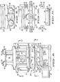
- Fig. 1 is a perspective view of a serial dilution machine implementing the features of the present invention;
- Fig. 2 is a sectional side view of the serial dilution machine taken in the direction of arrows 2-2 in Fig. 1;
- Fig. 3 is an enlarged, sectional side view of one embodiment of a pipette tip in a tip support tray well;
- Fig. 4 is an enlarged, sectional side view of a preferred form of pipette tip supported in a tip tray well;
- Fig. 5 is an enlarged, sectional side view of the plunger and pipette assembly;
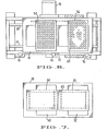
- Fig. 6 is a top view of the table- showing the trays arranged thereon for a 12 x 7 diluter configuration;
- Fig. 7 is a top view of the table showing the trays arranged for an 8 x 11 diluter configuration;
- Fig. 8 is a sectional front view of the automatic serial dilution machine taken in the direction of arrows 8-8 in Fig. 1;
- Fig. 9 is a partial top plan view of the machine;
- Fig. 10 is a sectional top view taken along the section line 10-10 of Fig. 8;
- Fig. 11 is a sectional top view taken along the section line 11-11 of Fig. 8.
- Fig. 12 is a perspective view of an alternate embodiment of a serial dilution machine including a fluid transfer or supply tray between the tip supply tray and the microtiter tray;
- Fig. 13 is top plan view of the Fig. 12 table embodiment; and
- Fig. 14 is a sectional side view taken in the direction of arrows 14-14 in Fig. 13.
- Referring to Figures 1 and 2, an automatic serial dilution machine suitable for carrying out the method of the present invention includes two main movable parts, a horizontally translatable table 10 and a vertically
translatable head assembly 12. As best illustrated in Fig. 2, the table 10 is mounted for horizontal translation on hardenedguide rods 14 by means ofslide bearings 16. Translation of the table is provided by astepper motor 18 through apinion 20 connected to the motor and arack 22 mounted on the underside of the table. Similarly, thehead 12 is mounted for vertical translation onguide rods 24 by means ofslide bearings 26. Translation of the head assembly is provided by astepper motor 28 through apinion 30 and arack 32. - The
head assembly 12 supports a pipette andplunger assembly 34. This assembly includes a series ofpipettes 36 that are arranged in a row transverse to the axis of translation of the table 10. The pipettes are removably attached to the head assembly by means of a mountingblock 37, and connectingpins 33 and move therewith. Aplunger mechanism 38 is mounted on the head assembly for vertical movement relative to the pipettes. The plunger mechanism includes a series ofplunger rods 40, one being disposed respectively within eachpipette 36. All of the rods are mounted on acommon actuator bar 42 for concurrent vertical movement. Thebar 42 is translated alongguide rods 44 by means of astepper motor 46 and a ballscrew drive mechanism 48. As best illustrated in the detailed sectional diagram of Fig. 5, translation of theplunger rods 40 relative to thepipettes 36 changes the internal volumes of the pipettes, causing fluid to be aspirated into or expelled from them. An air tight seal is provided between each rod and the top of its associated pipette by means of an O-ring 49, held bygrommet 47 andcompliance spring 45. Eachpipette 36 includes apiston section 39 which is reciprocably mounted in a cylinder 35 formed in mountingblock 37.Pipette 36 is thereby restrained vertically byspring 45 so that during the tip loading step,pipette 36 can slide vertically inblock 37 againstcompliance spring 45. This allows all pipettes to reliably pick up tips of slightly different dimensions and to assure that the open ends oftips 62 are at the same elevation relative to table 10 andtiter tray 54. - The table 10 includes two
work stations conventional titer tray 54 that includes a matrix arrangement of wells for housing the liquid sample and the diluent. Theother tray 56 at therear work station 52 can be a tip tray that contains a similar arrangement of receptacles that accommodate disposable pipette tips. A typical titer tray contains 96 wells in a 12 x 8 matrix pattern. As illustrated in Fig. 6, thetray 54 can be accommodated at theforward work station 50 in a transverse orientation to perform a 12 x 7 serial dilution, wherein the first row of wells is filled with a predetermined volume of the sample to be diluted, and the remaining wells are filled with the diluent. In this case, thetip tray 56 is also oriented to present twelve receptacles in a row across the width of the tray. Alternatively, as illustrated in Fig. 7, thetrays - Referring again to the detailed side view of Fig. 5, the
bottom end 60 of eachpipette 36 is tapered on its exterior surface so as to receive and frictionally engage the inner surface ofdisposable pipette tip 62 constructed in accordance with the present invention. For example, thetip 62 might be made of a non-wettable polypropylene material. Thetips 62 in a row of wells orreceptacles 63 in thetip tray 56 are inserted onto and engage the respective ends of thepipettes 36 when thehead assembly 12 is lowered by thestepper motor 28 after the table 10 has brought one row oftips 62 into registry with the pipettes. As indicated, the volume of eachtip 62 is a substantial portion of the total volume of the cylinder formed by the barrel ofpipette 36 and the interior volume of the tip. As best seen in Figs. 4 and 5, support of eachtip 62 inreceptacle 63 oftray 56 is either by end support as in Fig. 4 or on ends of the bottom flutes 65 formed on the exterior oftips 62. The wall ofreceptacles 63 are arranged to centertip 62 for engagement with taperedend 60 ofpipette 36. - The subsequent removal of the
tips 62 from the pipettes is accomplished with a tip ejector means. The tip ejector means includes a comb-like plate 64 that is best illustrated in Fig. 11. The plate has recesses that accommodate the pipettes, and its teeth surround a substantial portion, e.g., 180°, of the exterior circumference of each pipette barrel. Theplate 64 is connected to and supported by a pair of verticallytranslatable rods 66 mounted on thehead assembly 12. These rods are translated by means of a pair ofsolenoids 68 mounted on the top of the head assembly. When thesolenoids 68 are deactuated, theejector plate 64 is maintained in the upper position illustrated in Fig. 5. Actuation of the solenoids moves the plate vertically downward, to push thetips 62 down and release them from their frictional engagement with the ends of thepipettes 36. - The operation of each of the
stepper motors solenoids 68 is controlled by asuitable microprocessor 70. Basically, themicroprocessor 70 functions as a pulse generator to control the sequence of operations of each of these elements, and thus the interrelated movements of the table 10, thehead assembly 12, theplunger assembly 34 and thetip ejector plate 64 to effect serial dilution of a sample in thetray 54 at theforward work station 50. Since the stepper motors provide a predetermined amount of rotation in response to each actuating pulse applied thereto, accurate positioning of the movable elements can be obtained through appropriate control of the number of actuating pulses supplied by the microprocessor. - In addition to controlling these various movable elements, the
microprocessor 70 also monitors their movement through appropriately positioned sensors. For example, a sensor arrangement for the table 10 can include ablade 72 that is attached to and extends from the side of the table, and a Hall-effect sensor 74 that detects when theblade 72, and hence the table 10, passes through a predetermined reference point in its translation. Each time the table passes through this point, the Hall-effect sensor 74 sends a signal to themicroprocessor 70 that enables the microprocessor to update information relating to the table's position. Thus, if thestepper motor 18 should miss an actuating pulse during translation of the table, or if the pulse count stored within themicroprocessor 70 should not coincide with the position of the table, the error will not be carried over to successive cycles of operation. - In addition to the
reference sensor 74, a pair oflimit sensors 76 can be disposed at the respective ends of the path of travel of the table. A signal sent by these sensors indicates that the table is nearing the end of its travel, and provides an indication to themicroprocessor 70 to interrupt the supply of power to thestepper motor 18 or take some other such corrective action. Similar sensor arrangements are provided to monitor the movement of thehead assembly 12 and theplunger bar 42. - Furthermore, a sensor can be provided on the machine to detect whether all of the tips in a row of the
tray 56 have been picked up by the pipette assembly. Referring to Figure 8, this sensor can include an electrical-optical mechanism comprising anLED 89 or similar such light emitting device on one side of the table and aphotoelectric element 90 on the other side of the table. The two elements are aligned with the row ofpipettes 36. When one ormore tips 62 are present within the row ofwells 63 registered with the sensor, the light beam 82 from the LED will be broken and will not reach thephotoelectric element 90. However, if all of the tips in a row are successfully picked up by the pipette assembly, the beam will extend across thetray 56 and be detected by the photoelectric element. Byproper positioning LED 89 andphotoelectric element 90, possible pick up oftray 56 itself, as by friction betweentips 62 and wells intray 56, can also be detected. - Figs. 12 to 14 illustrate an alternative embodiment of the moveable table arrangement of the present invention. This embodiment includes another
microtiter tray 88 betweensample tray 54 andtip supply tray 56.Tray 88 may contain either a liquid supply of biological material or a reagent for initially filling the titer tray receptacles. While shown as a plurality of individual wells,tray 88 may be a common supply trough or pan. For example the initial charge of sample material may be injected into a first row of receptacles intray 54 and after replacement oftips 62 fromtray 56, the remaining wells in 56 filled with diluent transferred from another portion oftray 88 or a separate supply of liquid from another tray. As mentioned above, after use, pipette tips may be ejected into empty receptacles intip tray 56. However, it is also contemplated that another portion of table 10 would permit collection of all used tips. This may either be a slot in table 10 (not shown) permitting drop of the tips into a bin below the table, or a collection bin located at another position on the table. - In operation, the automatic serial dilutor basically functions to pick up a row of tips in the
tray 56, insert them in one row of wells in thetiter tray 54, extract some of the liquid sample from these wells, inject the tips into the diluent in the next successive row of wells, oscillate the plungers to mix the liquid, position the tips to expell all liquid and then return the tips to thetray 56. This operation is set forth in greater detail with reference to the following example of a program that can be used by the microprocessor to effect a serial dilution process.

- The cycle is repeated a number of times equal to the number of dilutions to be carried out. During any given cycle steps 001-004 and 18-22 can be deleted if changing of the tips is not required.
- Prior to the initiation of a serial dilution operation, the
microprocessor 70 can be programmed with the volume of liquid that is to be transferred during each cycle of the process. This amount determines the extent to which theplunger rods 40 are raised during step 007 of the program. This action, in turn, determines the concentration of the sample in successive wells of thetray 54. For example, to obtain a dilution spectrum in which the concentration in one row is one-half that of the preceding row, the first row of wells might be filled with 100 )1 of the sample and all other wells filled with 50 )1 of diluent each. The microprocessor would be set up to cause 50 )1 to be transferred from one well to the next succeeding well during each cycle. - During step 011, the
plunger rods 40 can be oscillated up and down about 5 times to assure adequate mixing. - At the beginning of each cycle of the serial dilution process, the
plunger rods 40 are disposed at a predetermined calibration point within the pipettes. A Hall-effect sensor similar to the type described previously with respect to the table 10 can be used to monitor and control the position of the rods. In step number 014 of the program, after the sample and diluent have been mixed in step 011, the plunger tips are raised so that they are just above the level of liquid in the wells in step 012 and the plunger returned to the calibration point to expel the liquid from the pipettes in step 013, the tips are raised to a point just above the meniscus of liquid in the receptacle. By then extending the plungers downwardly beyond the calibration point, all liquid is expelled from the pipettes. This action effectively blows the liquid out of the pipettes by causing some air trapped within the pipette to also be ejected and permits any liquid remaining in the tips and extending between the tip and the receptacle to be drawn out of the tip by capillary action due to surface tension acting on the liquid. This step is particularly effective where the tip is made of a non-wettable plastic which as above noted is a preferred material. - Although certain steps have been shown to be discrete, they can be executed simultaneously. For example, steps 016 and 017 might take place at the same time.
- It will be appreciated by those of ordinary skill in the art that the present invention can be embodied in other specific forms without departing from the spirit or essential characteristics thereof. The presently disclosed embodiment is therefore considered in all respects to be illustrative and not restrictive. For example, where the term "stepper" motor has been used to describe the preferred embodiment of the motor drive means for table, head assembly and plunger mechanism, it will be apparent that other precise positioning means may be used, such as direct current servo motors. The scope of the invention accordingly is indicated by the appended claims rather than the foregoing description, and all changes that come within the range of equivalence thereof are intended to be embraced therein.
Claims (10)
Priority Applications (1)
| Application Number | Priority Date | Filing Date | Title |
|---|---|---|---|
| AT84100588T ATE46971T1 (en) | 1983-01-21 | 1984-01-20 | DEVICE AND METHOD FOR TREATMENT OF LIQUID SAMPLES. |
Applications Claiming Priority (4)
| Application Number | Priority Date | Filing Date | Title |
|---|---|---|---|
| US45997383A | 1983-01-21 | 1983-01-21 | |
| US459973 | 1983-01-21 | ||
| US489866 | 1983-05-05 | ||
| US06/489,866 US4478094A (en) | 1983-01-21 | 1983-05-05 | Liquid sample handling system |
Publications (3)
| Publication Number | Publication Date |
|---|---|
| EP0114686A2 true EP0114686A2 (en) | 1984-08-01 |
| EP0114686A3 EP0114686A3 (en) | 1985-04-03 |
| EP0114686B1 EP0114686B1 (en) | 1989-10-04 |
Family
ID=27039534
Family Applications (1)
| Application Number | Title | Priority Date | Filing Date |
|---|---|---|---|
| EP84100588A Expired EP0114686B1 (en) | 1983-01-21 | 1984-01-20 | Liquid sample handling system |
Country Status (11)
| Country | Link |
|---|---|
| US (1) | US4478094A (en) |
| EP (1) | EP0114686B1 (en) |
| KR (1) | KR900005608B1 (en) |
| AT (1) | ATE46971T1 (en) |
| AU (1) | AU556726B2 (en) |
| CA (1) | CA1183816A (en) |
| DE (2) | DE114686T1 (en) |
| DK (1) | DK20084A (en) |
| FI (1) | FI840233A (en) |
| NO (1) | NO162637C (en) |
| NZ (1) | NZ206913A (en) |
Cited By (20)
| Publication number | Priority date | Publication date | Assignee | Title |
|---|---|---|---|---|
| EP0140247A2 (en) * | 1983-10-14 | 1985-05-08 | Cetus Corporation | Multiple trough vessel for automated liquid handling apparatus |
| WO1986002168A1 (en) * | 1984-10-01 | 1986-04-10 | Cetus Corporation | Automated assay machine and assay tray |
| FR2597607A1 (en) * | 1987-04-10 | 1987-10-23 | Helena Lab Corp | Automatic pipette applicator apparatus |
| FR2609808A1 (en) * | 1987-01-19 | 1988-07-22 | Api System | APPARATUS FOR DISTRIBUTING MEDIA INTO GROUPED RECEPTACLES ON PLATES |
| EP0306276A2 (en) * | 1987-08-31 | 1989-03-08 | Ngk Insulators, Ltd. | Method and apparatus for vitrifying and analysing powdery and granular materials |
| EP0425690A1 (en) * | 1989-04-25 | 1991-05-08 | Kyoto Daiichi Kagaku Co., Ltd. | Method of detecting operation condition of a micropipette |
| US5257302A (en) * | 1987-08-31 | 1993-10-26 | Ngk Insulators, Ltd. | Fluorescent X-ray analyzing system |
| US5358641A (en) * | 1989-10-27 | 1994-10-25 | Helena Laboratories Corporation | Column analyzer system and improved chromatograph column for use in the system |
| WO1999028724A1 (en) * | 1997-11-27 | 1999-06-10 | A.I. Scientific Pty. Ltd. | A sample distribution apparatus/system |
| GB2361995A (en) * | 2000-05-05 | 2001-11-07 | Cybio Instr Gmbh | Tip removal in an automatic pipettor |
| US7374720B2 (en) | 2002-11-18 | 2008-05-20 | Hitachi Koki Co., Ltd. | Control device for automatic liquid handling system |
| CN1912627B (en) * | 2006-08-23 | 2011-05-11 | 陕西北美基因股份有限公司 | Blood treatment working station based on micronano magnetic particle and its control method |
| WO2013156418A3 (en) * | 2012-04-17 | 2013-12-12 | Hamilton Bonaduz Ag | Pipetting machine having a disposal container |
| EP2698631A2 (en) * | 2011-03-25 | 2014-02-19 | Micobiomed Co., Ltd. | Optical sensor strip and diagnostic device comprising same |
| WO2014140640A1 (en) * | 2013-03-15 | 2014-09-18 | Diagnostics For The Real World, Ltd | Apparatus and method for automated sample preparation and adaptor for use in the apparatus |
| EP1980334A4 (en) * | 2006-02-02 | 2017-05-24 | Musashi Engineering, Inc. | Pallet for fixing work and liquid applying apparatus provided with same |
| EP2803412A3 (en) * | 2013-05-17 | 2017-12-20 | Stratec Biomedical AG | Device and Method for Supplying Disposable Tips to a Pipetting System |
| EP3501655A1 (en) * | 2017-12-21 | 2019-06-26 | Integra Biosciences AG | Sample distribution system and method for distributing samples |
| EP3765197A4 (en) * | 2018-04-06 | 2021-12-08 | Muscle Lab Canada Inc. | Integrated pipetting apparatus |
| WO2022025924A1 (en) * | 2020-07-31 | 2022-02-03 | Baxalta Incorporated | Grip detection system for liquid handling robot |
Families Citing this family (153)
| Publication number | Priority date | Publication date | Assignee | Title |
|---|---|---|---|---|
| US4626509A (en) * | 1983-07-11 | 1986-12-02 | Data Packaging Corp. | Culture media transfer assembly |
| US4555957A (en) * | 1983-10-14 | 1985-12-03 | Cetus Corporation | Bi-directional liquid sample handling system |
| JPS60237369A (en) * | 1984-05-11 | 1985-11-26 | Eisai Co Ltd | Continuous measuring apparatus for reaction solution in very small container |
| IT1174039B (en) * | 1984-06-19 | 1987-06-24 | Finbiomedica Srl | METHOD AND EQUIPMENT FOR HIGH SPEED AUTOMATIC CHEMICAL-CLINICAL ANALYSIS |
| US4728501A (en) * | 1984-07-27 | 1988-03-01 | Minoru Atake | Adjustable liquid sampling apparatus |
| US4952518A (en) * | 1984-10-01 | 1990-08-28 | Cetus Corporation | Automated assay machine and assay tray |
| DE185330T1 (en) * | 1984-12-18 | 1986-11-27 | Cetus Corp., Emeryville, Calif. | SYSTEM FOR TREATING MULTIPLE SAMPLES. |
| US4602517A (en) * | 1985-02-11 | 1986-07-29 | Schultz Harold R | Fluid sampling method and apparatus |
| US4720463A (en) * | 1985-03-01 | 1988-01-19 | Sherwood Medical Company | Automated microbiological testing apparatus |
| US5656493A (en) * | 1985-03-28 | 1997-08-12 | The Perkin-Elmer Corporation | System for automated performance of the polymerase chain reaction |
| US5333675C1 (en) * | 1986-02-25 | 2001-05-01 | Perkin Elmer Corp | Apparatus and method for performing automated amplification of nucleic acid sequences and assays using heating and cooling steps |
| US5038852A (en) * | 1986-02-25 | 1991-08-13 | Cetus Corporation | Apparatus and method for performing automated amplification of nucleic acid sequences and assays using heating and cooling steps |
| NO862717L (en) * | 1985-07-05 | 1987-01-06 | Cetus Corp | PROCEDURE AND APPARATUS FOR AUTOMATIC BODY TREATMENT. |
| US4873633A (en) * | 1985-10-18 | 1989-10-10 | Cetus Corporation | User controlled off-center light absorbance reading adjuster in a liquid handling and reaction system |
| CH671526A5 (en) * | 1985-12-17 | 1989-09-15 | Hamilton Bonaduz Ag | |
| JPS63502929A (en) * | 1986-03-20 | 1988-10-27 | ベックマン インスツルメンツ インコーポレーテッド | modular storage system |
| US5104621A (en) * | 1986-03-26 | 1992-04-14 | Beckman Instruments, Inc. | Automated multi-purpose analytical chemistry processing center and laboratory work station |
| US5139744A (en) * | 1986-03-26 | 1992-08-18 | Beckman Instruments, Inc. | Automated laboratory work station having module identification means |
| US5108703A (en) * | 1986-03-26 | 1992-04-28 | Beckman Instruments, Inc. | Automated multi-purpose analytical chemistry processing center and laboratory work station |
| US4827780A (en) * | 1986-04-17 | 1989-05-09 | Helena Laboratories Corporation | Automatic pipetting apparatus |
| CA1286389C (en) * | 1986-04-17 | 1991-07-16 | Robert J. Sarrine | Automatic pipetting apparatus |
| US4938080A (en) * | 1986-04-17 | 1990-07-03 | Helena Laboratories, Inc. | Automatic pipetting apparatus |
| GB8617508D0 (en) * | 1986-07-17 | 1986-08-28 | Flow Lab | Liquid handling station |
| US4779467A (en) * | 1987-01-28 | 1988-10-25 | Rainin Instrument Co., Inc. | Liquid-end assembly for multichannel air-displacement pipette |
| GB8704267D0 (en) * | 1987-02-24 | 1987-04-01 | Fisons Plc | Device |
| CA1285536C (en) * | 1987-03-11 | 1991-07-02 | Akihiro Ohoka | Dispensing machine |
| US4863695A (en) * | 1987-04-28 | 1989-09-05 | Hewlett-Packard Company | Pipette assembly |
| US4790183A (en) * | 1987-05-05 | 1988-12-13 | Beckman Instruments, Inc. | Acoustic impedance system for liquid boundary level detection |
| EP0311440B1 (en) * | 1987-10-09 | 1992-06-24 | Seiko Instruments Inc. | Apparatus for carrying out a liquid reaction |
| US5055263A (en) * | 1988-01-14 | 1991-10-08 | Cyberlab, Inc. | Automated pipetting system |
| US5045286A (en) * | 1988-02-25 | 1991-09-03 | Olympus Optical Co., Ltd. | Device for aspirating a fixed quantity of liquid |
| US4927765A (en) * | 1988-02-29 | 1990-05-22 | Pharmacia Eni Diagnostics, Inc. | Automatic reagent dispenser |
| WO1989010193A1 (en) * | 1988-04-29 | 1989-11-02 | Cavro Scientific Instruments, Inc. | Improved method and apparatus for pipetting liquids |
| US4967606A (en) * | 1988-04-29 | 1990-11-06 | Caveo Scientific Instruments, Inc. | Method and apparatus for pipetting liquids |
| US4846003A (en) * | 1988-06-08 | 1989-07-11 | Beckman Instruments, Inc. | Acoustic impedance system for pipette tip detection |
| US5046539A (en) * | 1989-05-26 | 1991-09-10 | The Rockefeller University | Automatic fluid dispenser for multi-welled dish |
| US4936152A (en) * | 1989-05-30 | 1990-06-26 | Aldred Dennis A | Pipette tip storage tray and method of use |
| US5173265A (en) * | 1989-07-24 | 1992-12-22 | Helena Laboratories Corporation | Manually operated pump inserter for test tubes |
| US5055271A (en) * | 1989-07-24 | 1991-10-08 | Helena Laboratories Corporation | Pump inserter for test tubes |
| GB9012949D0 (en) * | 1989-08-25 | 1990-08-01 | Ibm | An apparatus and method for loading bios from a diskette in a personal computer system |
| US5201231A (en) * | 1989-10-04 | 1993-04-13 | Dorothy A. Smith | Volumetric air sampler for collecting multiple discrete samples |
| US5262128A (en) * | 1989-10-23 | 1993-11-16 | The United States Of America As Represented By The Department Of Health And Human Services | Array-type multiple cell injector |
| US5092184A (en) * | 1989-12-22 | 1992-03-03 | Medical Research Institute Of The Mary Imogene Bassett Hospital | Cell staining system for flow cytometry |
| JPH087222B2 (en) * | 1990-01-18 | 1996-01-29 | 持田製薬株式会社 | Automatic dispensing dilution device |
| US5141871A (en) * | 1990-05-10 | 1992-08-25 | Pb Diagnostic Systems, Inc. | Fluid dispensing system with optical locator |
| US5200151A (en) * | 1990-05-21 | 1993-04-06 | P B Diagnostic Systems, Inc. | Fluid dispensing system having a pipette assembly with preset tip locator |
| DE4023182A1 (en) * | 1990-07-20 | 1992-01-23 | Kodak Ag | Device for moving pipettes in analyser - moves plate shaped pipette tray to processing station of analyser for alignment with pipette tray resting on moving unit |
| DE4023165A1 (en) * | 1990-07-20 | 1992-01-23 | Kodak Ag | DEVICE FOR SCANING AND CENTERING CONTAINERS WITH A LIQUID |
| KR100236506B1 (en) * | 1990-11-29 | 2000-01-15 | 퍼킨-엘머시터스인스트루먼츠 | Apparatus for polymerase chain reaction |
| US5138868A (en) * | 1991-02-13 | 1992-08-18 | Pb Diagnostic Systems, Inc. | Calibration method for automated assay instrument |
| US5190727A (en) * | 1991-07-18 | 1993-03-02 | Eastman Kodak Company | Device for moving and positioning pipette trays in an analyzer |
| US5226462A (en) * | 1991-07-26 | 1993-07-13 | Carl Richard A | Introducing measured amounts of liquid into receptacles |
| US6864101B1 (en) * | 1991-11-22 | 2005-03-08 | Affymetrix, Inc. | Combinatorial strategies for polymer synthesis |
| US6943034B1 (en) * | 1991-11-22 | 2005-09-13 | Affymetrix, Inc. | Combinatorial strategies for polymer synthesis |
| ATE170293T1 (en) * | 1992-06-08 | 1998-09-15 | Behring Diagnostics Inc | FLUID DISPENSER SYSTEM |
| US5290521A (en) * | 1992-09-04 | 1994-03-01 | Destefano Jr Albert M | Lab-top work station |
| JPH08511871A (en) * | 1993-06-21 | 1996-12-10 | ベーリンガー・マンハイム・コーポレーション | Front-end device and method |
| JPH07159309A (en) * | 1993-12-07 | 1995-06-23 | Shokuhin Sangyo Intelligence Control Gijutsu Kenkyu Kumiai | Powder sample adjusting apparatus |
| DE4339143A1 (en) * | 1993-11-16 | 1995-05-18 | Jenoptron Ges Fuer Optoelektro | Automatic sample dispensing appts. |
| US5497670A (en) * | 1995-03-31 | 1996-03-12 | Carl; Richard A. | Liquid dispensing apparatus including means for loading pipette tips onto liquid dispensing cylinders and maintaining the loading force during the apparatus operation cycle |
| US5537880A (en) * | 1995-06-07 | 1996-07-23 | Abbott Laboratories | Automatic pipetting apparatus with leak detection and method of detecting a leak |
| DE19604100C2 (en) * | 1996-02-06 | 1997-12-18 | Bosch Gmbh Robert | Device for handling fillable tubular objects arranged in an upwardly open container |
| US5915284A (en) * | 1996-07-22 | 1999-06-22 | Cyberlab, Inc. | Multiple channel pipetting device |
| WO1998010265A1 (en) * | 1996-09-09 | 1998-03-12 | Tyco Group S.A.R.L. | Electronically monitored mechanical pipette |
| EP1007211A1 (en) * | 1997-04-05 | 2000-06-14 | Steinbrenner, Bernd, Dr. | Device for picking up and distributing laboratory objects with at least in part a hollow cylindrical contour |
| CA2287962C (en) | 1997-05-02 | 2007-01-02 | Gen-Probe Incorporated | Reaction receptacle apparatus |
| US5985214A (en) | 1997-05-16 | 1999-11-16 | Aurora Biosciences Corporation | Systems and methods for rapidly identifying useful chemicals in liquid samples |
| ATE270151T1 (en) * | 1997-08-08 | 2004-07-15 | Aventis Pharma Gmbh | PIPETTING ROBOT WITH TEMPERATURE DEVICE |
| US5952240A (en) * | 1997-09-09 | 1999-09-14 | Pharmacopeia, Inc. | Discrete matrix plate positioner |
| US6254826B1 (en) * | 1997-11-14 | 2001-07-03 | Gen-Probe Incorporated | Assay work station |
| US7470547B2 (en) * | 2003-07-31 | 2008-12-30 | Biodot, Inc. | Methods and systems for dispensing sub-microfluidic drops |
| US20020159919A1 (en) * | 1998-01-09 | 2002-10-31 | Carl Churchill | Method and apparatus for high-speed microfluidic dispensing using text file control |
| US6063339A (en) * | 1998-01-09 | 2000-05-16 | Cartesian Technologies, Inc. | Method and apparatus for high-speed dot array dispensing |
| US6415669B1 (en) * | 1998-04-09 | 2002-07-09 | Ccs Packard, Inc. | Dispensing apparatus having means for loading pipette tips in a dispense head |
| JPH11295323A (en) * | 1998-04-13 | 1999-10-29 | Matsushita Electric Ind Co Ltd | Automatic dispenser and its method |
| EP1614475B1 (en) * | 1998-05-01 | 2007-05-30 | Gen-Probe Incorporated | Device for agitating the fluid contents of a container |
| US6551557B1 (en) | 1998-07-07 | 2003-04-22 | Cartesian Technologies, Inc. | Tip design and random access array for microfluidic transfer |
| US5988236A (en) * | 1998-07-31 | 1999-11-23 | Gilson, Inc. | Multiple syringe pump assembly for liquid handler |
| US6309891B1 (en) * | 1998-09-09 | 2001-10-30 | Incyte Genomics, Inc. | Capillary printing systems |
| US6039211A (en) * | 1998-09-22 | 2000-03-21 | Glaxo Wellcome Inc. | Position triggered dispenser and methods |
| DE19845950C1 (en) * | 1998-10-06 | 2000-03-23 | Eppendorf Geraetebau Netheler | Mechanism for the separation of a tip from a pipette has an ejection unit operated by a pull drive to exert an axial separation between the pipette and its mounting without contamination |
| JP3587066B2 (en) * | 1998-10-12 | 2004-11-10 | 松下電器産業株式会社 | Automatic dispensing device |
| JP2000121511A (en) * | 1998-10-13 | 2000-04-28 | Hitachi Koki Co Ltd | Automatic separation and extraction device and its control method |
| US7199809B1 (en) | 1998-10-19 | 2007-04-03 | Symyx Technologies, Inc. | Graphic design of combinatorial material libraries |
| US6247891B1 (en) | 1998-12-18 | 2001-06-19 | Labcon, North America | Apparatus for transporting pipette tips |
| US20020176801A1 (en) * | 1999-03-23 | 2002-11-28 | Giebeler Robert H. | Fluid delivery and analysis systems |
| US6589791B1 (en) * | 1999-05-20 | 2003-07-08 | Cartesian Technologies, Inc. | State-variable control system |
| US6979425B1 (en) * | 1999-10-04 | 2005-12-27 | Robodesign International, Inc. | High capacity microarray dispensing |
| US6739448B1 (en) | 2000-02-01 | 2004-05-25 | Incyte Corporation | Method and apparatus for shuttling microtitre plates |
| US6325114B1 (en) * | 2000-02-01 | 2001-12-04 | Incyte Genomics, Inc. | Pipetting station apparatus |
| US6399024B1 (en) | 2000-02-01 | 2002-06-04 | Incyte Genomics, Inc. | Multichannel pipette head |
| US6629626B1 (en) * | 2000-03-07 | 2003-10-07 | Dyax, Corporation | Liquid transfer device |
| JP2004501745A (en) * | 2000-06-26 | 2004-01-22 | ビスタラブ テクノロジーズ インク | Automatic pipette identification and tip removal |
| AU2001275197A1 (en) * | 2000-06-26 | 2002-01-08 | Vistalab Technologies, Inc. | Handheld pipette |
| DE10040849A1 (en) * | 2000-08-21 | 2002-03-21 | Mwg Biotech Ag | Pipetting head for a robot with several pipetting tips |
| US6780648B1 (en) * | 2000-09-20 | 2004-08-24 | General Electric Company | Method and system for selectively distributing luminescence material precursors |
| US7714301B2 (en) * | 2000-10-27 | 2010-05-11 | Molecular Devices, Inc. | Instrument excitation source and calibration method |
| DE10059702B4 (en) * | 2000-12-01 | 2004-05-06 | Eppendorf Ag | dosing |
| AU2002228777A1 (en) * | 2000-12-05 | 2002-06-18 | Robbins Scientific Corporation | Self-aligning nozzle array for pipette tip array plate |
| US20020108857A1 (en) * | 2000-12-18 | 2002-08-15 | Michael Paschetto | Automated laboratory system and method |
| US6669911B1 (en) | 2001-01-31 | 2003-12-30 | David W. Swanson | Frame for multiwell tray |
| US7510684B2 (en) * | 2001-02-09 | 2009-03-31 | Beckman Coulter, Inc. | Latch system and modified blade design for thick stopper-closed container sampling piercing station |
| DE60217303T2 (en) * | 2001-02-28 | 2007-08-30 | Iogen Energy Corp., Nepean | METHOD FOR TREATING LIGNIN AND CELLULOSIC SUBSTANCES FOR INCREASED PRODUCTION OF XYLOSE AND ETHANOL |
| US20060029955A1 (en) | 2001-03-24 | 2006-02-09 | Antonio Guia | High-density ion transport measurement biochip devices and methods |
| US20050009004A1 (en) * | 2002-05-04 | 2005-01-13 | Jia Xu | Apparatus including ion transport detecting structures and methods of use |
| US20050196746A1 (en) * | 2001-03-24 | 2005-09-08 | Jia Xu | High-density ion transport measurement biochip devices and methods |
| WO2002077259A2 (en) * | 2001-03-24 | 2002-10-03 | Aviva Biosciences Corporation | Biochips including ion transport detecting structures and methods of use |
| US20050058990A1 (en) * | 2001-03-24 | 2005-03-17 | Antonio Guia | Biochip devices for ion transport measurement, methods of manufacture, and methods of use |
| US6752182B2 (en) * | 2001-06-28 | 2004-06-22 | Genetix Limited | Microarraying apparatus, pin head therefor and spotting method |
| US20030149933A1 (en) * | 2002-02-01 | 2003-08-07 | Marco Falcioni | Graphical design of chemical discovery processes |
| US6793891B2 (en) * | 2002-04-08 | 2004-09-21 | Felxi Yiu | Pipettor and externally sealed pipette tip |
| US6780381B2 (en) | 2002-04-08 | 2004-08-24 | Felix H. Yiu | Pipettor and externally sealed pipette tip |
| US20040087010A1 (en) * | 2002-11-04 | 2004-05-06 | Chung-Hua Tsai | Micro ELISA reader |
| FI120861B (en) * | 2002-11-08 | 2010-04-15 | Biohit Oyj | multichannel pipette |
| JP4072724B2 (en) * | 2003-04-16 | 2008-04-09 | 日立工機株式会社 | Automatic dispensing device |
| WO2004105951A1 (en) * | 2003-05-28 | 2004-12-09 | Hte Aktiengesellschaft The High Throughput Experimentation Company | Modular sample holder system |
| US7396512B2 (en) | 2003-11-04 | 2008-07-08 | Drummond Scientific Company | Automatic precision non-contact open-loop fluid dispensing |
| US7055402B2 (en) * | 2003-12-19 | 2006-06-06 | Gilson, Inc. | Method and apparatus for liquid chromatography automated sample loading |
| DE102004016003B4 (en) * | 2004-04-01 | 2006-05-04 | Eppendorf Ag | Electronic pipette |
| US7455814B2 (en) * | 2004-04-23 | 2008-11-25 | Giblin Leonard J | Metered dispenser and aspirator device |
| DE102004046740B4 (en) * | 2004-06-07 | 2006-07-06 | Aviso Gmbh Mechatronic Systems | Tool head for a device for the automatic isolation and treatment of cell clones |
| KR100624458B1 (en) * | 2005-01-17 | 2006-09-19 | 삼성전자주식회사 | Handheld centrifuge |
| WO2006095424A1 (en) * | 2005-03-10 | 2006-09-14 | Fujitsu Limited | Pump unit, syringe unit, particle feeding method, and cell feeding method |
| FR2892821B1 (en) * | 2005-11-02 | 2008-02-01 | Concept Pro Sarl | INTEGRATED AND / OR AUTOMATED DEVICE FOR THE TRACKING AND / OR TRACEABILITY OF SAMPLING CONTAINERS OF MEDICAL OR VETERINARY PRIMARY SAMPLES |
| JP4179338B2 (en) * | 2006-05-22 | 2008-11-12 | 松下電器産業株式会社 | Dispensing device |
| WO2008039209A1 (en) * | 2006-09-27 | 2008-04-03 | The Scripps Research Institute | Microfluidic serial dilution circuit |
| US20080101996A1 (en) * | 2006-10-31 | 2008-05-01 | Taigen Bioscience Corporation | Multi-channel design for a liquid-handling pipette |
| IES20060872A2 (en) * | 2006-12-05 | 2008-09-17 | Trinity Res Ltd | A well plate for holding a sample during analysis and a method for analysing a sample |
| EP2136911A2 (en) | 2007-01-19 | 2009-12-30 | Biodot, Inc. | Systems and methods for high speed array printing and hybridization |
| US20090071267A1 (en) * | 2007-09-17 | 2009-03-19 | Greg Mathus | Pipette tip ejection mechanism |
| US20090104078A1 (en) * | 2007-10-18 | 2009-04-23 | Matrix Technologies Corporation | Apparatus and method for dispensing small volume liquid samples |
| USD620602S1 (en) | 2008-01-03 | 2010-07-27 | Vistalab Technologies, Inc. | Pipette |
| DE102010005722A1 (en) | 2010-01-26 | 2011-07-28 | Eppendorf AG, 22339 | Positioning device for a sample distribution device, sample distribution device with positioning device and method for positioning |
| EP2566618B8 (en) * | 2010-05-03 | 2014-07-09 | Integra Biosciences AG | Manually directed, multi-channel electronic pipetting system |
| US8367022B2 (en) * | 2010-05-03 | 2013-02-05 | Integra Biosciences Corp. | Unintended motion control for manually directed multi-channel electronic pipettor |
| US8951781B2 (en) | 2011-01-10 | 2015-02-10 | Illumina, Inc. | Systems, methods, and apparatuses to image a sample for biological or chemical analysis |
| WO2012100205A2 (en) | 2011-01-21 | 2012-07-26 | Biodot, Inc. | Piezoelectric dispenser with a longitudinal transducer and replaceable capillary tube |
| DE102011108537B4 (en) | 2011-07-26 | 2023-10-12 | Eppendorf Se | Positioning device for a laboratory device for distributing fluid samples and laboratory device with positioning device |
| WO2013192442A1 (en) * | 2012-06-22 | 2013-12-27 | Bio-Rad Laboratories, Inc. | Two station sample and washing system |
| US20140004020A1 (en) * | 2012-06-29 | 2014-01-02 | Molecular Bioproducts, Inc. | Stand for use with affinity capture |
| EP2703820B1 (en) * | 2012-08-31 | 2019-08-28 | F. Hoffmann-La Roche AG | Mobile tip waste rack |
| CN103163310A (en) * | 2013-03-15 | 2013-06-19 | 东南大学 | Multi-channel micro-volume sampling device |
| JP6781919B2 (en) | 2014-09-03 | 2020-11-11 | 国立研究開発法人産業技術総合研究所 | Electric pipette system, electric pipette and work procedure display device |
| CN106554901B (en) * | 2015-09-30 | 2019-06-14 | 精专生医股份有限公司 | The board of automatization abstraction nucleic acid and the syringe for cooperating it to use |
| CN105170210A (en) * | 2015-10-14 | 2015-12-23 | 东南大学 | Multi-channel liquid transfer device |
| EP3502710B1 (en) * | 2016-08-22 | 2023-07-26 | Universal Bio Research Co., Ltd. | Dispensing cylinder, and dispensing device and dispensing treatment method using same |
| IT201700024734A1 (en) * | 2017-03-06 | 2018-09-06 | Dani Instr Spa | PERFORMED SAMPLER DEVICE FOR GAS CHROMATOGRAPHY |
| US10758909B2 (en) * | 2017-07-25 | 2020-09-01 | Thomas A. HEDGLIN | Device to assist in manual transfer of pipette tips |
| DE102017130738A1 (en) | 2017-12-20 | 2019-06-27 | Analytik Jena Ag | Multi-channel pipettor and method of operating a multi-channel pipettor |
| JP7017942B2 (en) * | 2018-01-31 | 2022-02-09 | シスメックス株式会社 | Sample measurement system and sample measurement method |
| KR102306849B1 (en) | 2019-09-30 | 2021-09-28 | 연세대학교 산학협력단 | Liquid information sensor and method of driving the same |
| AU2021366390A1 (en) * | 2020-10-19 | 2023-06-22 | Yourgene Health Canada Inc. | Apparatus, system, and methods for handling labware |
| WO2023240079A1 (en) * | 2022-06-07 | 2023-12-14 | Beckman Coulter, Inc. | Pipetting instrument |
Citations (5)
| Publication number | Priority date | Publication date | Assignee | Title |
|---|---|---|---|---|
| US3188181A (en) * | 1963-03-11 | 1965-06-08 | Parke Davis & Co | Serial dilution machine |
| US3650306A (en) * | 1970-09-18 | 1972-03-21 | Cooke Eng Co | Laboratory dispensing apparatus |
| GB1497012A (en) * | 1975-05-30 | 1978-01-05 | Bodenseewerk Perkin Elmer Co | Procedure and device for automatic sampling with a flameless atomic absorption spectrometer |
| US4215092A (en) * | 1976-04-08 | 1980-07-29 | Osmo A. Suovaniemi | Apparatus for liquid portioning and liquid transferring |
| US4422151A (en) * | 1981-06-01 | 1983-12-20 | Gilson Robert E | Liquid handling apparatus |
Family Cites Families (10)
| Publication number | Priority date | Publication date | Assignee | Title |
|---|---|---|---|---|
| GB1014462A (en) * | 1963-08-24 | 1965-12-22 | Peter James Littlejohns Sequei | Multiple pipetting apparatus |
| US3443439A (en) * | 1967-12-05 | 1969-05-13 | Edgardo A Cruz | Automatic sampler |
| US3581575A (en) * | 1969-04-11 | 1971-06-01 | Fisons Ltd | Dispensing apparatus for receiving and discharging a precisely predetermined volume of fluid |
| US3802782A (en) * | 1970-08-19 | 1974-04-09 | Rohe Scientific Corp | Chemical analyzer performing sequential analysis of samples |
| US3696971A (en) * | 1970-09-24 | 1972-10-10 | Electro Nucleonics | Mechanism for simultaneously metering and dispensing liquids |
| US3776700A (en) * | 1971-12-08 | 1973-12-04 | Linbro Chem Co Inc | Serial dilution apparatus |
| FR2287941A1 (en) * | 1974-10-15 | 1976-05-14 | Marteau D Autry Eric | DEVICE FOR EJECTING THE REMOVABLE TIP OF A PIPETTE |
| US4047438A (en) * | 1975-04-04 | 1977-09-13 | Teruaki Sekine | Liquid quantitative dispensing apparatus |
| US3982438A (en) * | 1975-06-23 | 1976-09-28 | The Salk Institute For Biological Studies | Multiple sample pipetting apparatus |
| US4158035A (en) * | 1978-03-15 | 1979-06-12 | Byrd William J | Multiple sample micropipette |
-
1983
- 1983-05-05 US US06/489,866 patent/US4478094A/en not_active Expired - Lifetime
-
1984
- 1984-01-11 KR KR1019840000083A patent/KR900005608B1/en active IP Right Grant
- 1984-01-13 NO NO840136A patent/NO162637C/en unknown
- 1984-01-17 DK DK20084A patent/DK20084A/en not_active Application Discontinuation
- 1984-01-20 NZ NZ206913A patent/NZ206913A/en unknown
- 1984-01-20 AU AU23658/84A patent/AU556726B2/en not_active Ceased
- 1984-01-20 FI FI840233A patent/FI840233A/en not_active Application Discontinuation
- 1984-01-20 DE DE198484100588T patent/DE114686T1/en active Pending
- 1984-01-20 EP EP84100588A patent/EP0114686B1/en not_active Expired
- 1984-01-20 AT AT84100588T patent/ATE46971T1/en not_active IP Right Cessation
- 1984-01-20 CA CA000445764A patent/CA1183816A/en not_active Expired
- 1984-01-20 DE DE8484100588T patent/DE3480026D1/en not_active Expired
Patent Citations (5)
| Publication number | Priority date | Publication date | Assignee | Title |
|---|---|---|---|---|
| US3188181A (en) * | 1963-03-11 | 1965-06-08 | Parke Davis & Co | Serial dilution machine |
| US3650306A (en) * | 1970-09-18 | 1972-03-21 | Cooke Eng Co | Laboratory dispensing apparatus |
| GB1497012A (en) * | 1975-05-30 | 1978-01-05 | Bodenseewerk Perkin Elmer Co | Procedure and device for automatic sampling with a flameless atomic absorption spectrometer |
| US4215092A (en) * | 1976-04-08 | 1980-07-29 | Osmo A. Suovaniemi | Apparatus for liquid portioning and liquid transferring |
| US4422151A (en) * | 1981-06-01 | 1983-12-20 | Gilson Robert E | Liquid handling apparatus |
Cited By (35)
| Publication number | Priority date | Publication date | Assignee | Title |
|---|---|---|---|---|
| EP0140247A3 (en) * | 1983-10-14 | 1985-06-05 | Cetus Corporation | Multiple trough vessel for automated liquid handling apparatus |
| EP0140247A2 (en) * | 1983-10-14 | 1985-05-08 | Cetus Corporation | Multiple trough vessel for automated liquid handling apparatus |
| WO1986002168A1 (en) * | 1984-10-01 | 1986-04-10 | Cetus Corporation | Automated assay machine and assay tray |
| FR2609808A1 (en) * | 1987-01-19 | 1988-07-22 | Api System | APPARATUS FOR DISTRIBUTING MEDIA INTO GROUPED RECEPTACLES ON PLATES |
| WO1988005541A1 (en) * | 1987-01-19 | 1988-07-28 | Api System | Apparatus for dispensing means into receptacles arranged in groups on plates |
| FR2597607A1 (en) * | 1987-04-10 | 1987-10-23 | Helena Lab Corp | Automatic pipette applicator apparatus |
| US5137410A (en) * | 1987-08-31 | 1992-08-11 | Ngk Insulators, Ltd. | Material supply apparatus for transferring powdery, granular and conglomerated materials |
| EP0306276A2 (en) * | 1987-08-31 | 1989-03-08 | Ngk Insulators, Ltd. | Method and apparatus for vitrifying and analysing powdery and granular materials |
| EP0306276A3 (en) * | 1987-08-31 | 1991-01-09 | Ngk Insulators, Ltd. | Method and apparatus for vitrifying and analysing powdery and granular materials |
| US5257302A (en) * | 1987-08-31 | 1993-10-26 | Ngk Insulators, Ltd. | Fluorescent X-ray analyzing system |
| EP0425690A1 (en) * | 1989-04-25 | 1991-05-08 | Kyoto Daiichi Kagaku Co., Ltd. | Method of detecting operation condition of a micropipette |
| EP0425690A4 (en) * | 1989-04-25 | 1992-03-18 | Kyoto Daiichi Kagaku Co., Ltd. | Method of detecting operation condition of a micropipette |
| US5358641A (en) * | 1989-10-27 | 1994-10-25 | Helena Laboratories Corporation | Column analyzer system and improved chromatograph column for use in the system |
| US5589063A (en) * | 1989-10-27 | 1996-12-31 | Helena Laboratories Corporation | Column analyzer system and improved chromatograph column for use in the system |
| US5595664A (en) * | 1989-10-27 | 1997-01-21 | Helena Laboratories Corporation | Column analyzer system and improved chromatograph column for use in the system |
| WO1999028724A1 (en) * | 1997-11-27 | 1999-06-10 | A.I. Scientific Pty. Ltd. | A sample distribution apparatus/system |
| GB2361995A (en) * | 2000-05-05 | 2001-11-07 | Cybio Instr Gmbh | Tip removal in an automatic pipettor |
| US6732598B2 (en) | 2000-05-05 | 2004-05-11 | Cybio Instruments Gmbh | Automatic pipettor with a single-row, multi-channel pipetting head |
| GB2361995B (en) * | 2000-05-05 | 2004-02-04 | Cybio Instr Gmbh | Automatic pipettor with a single-row multi-channel pipetting head |
| US7374720B2 (en) | 2002-11-18 | 2008-05-20 | Hitachi Koki Co., Ltd. | Control device for automatic liquid handling system |
| EP1980334A4 (en) * | 2006-02-02 | 2017-05-24 | Musashi Engineering, Inc. | Pallet for fixing work and liquid applying apparatus provided with same |
| CN1912627B (en) * | 2006-08-23 | 2011-05-11 | 陕西北美基因股份有限公司 | Blood treatment working station based on micronano magnetic particle and its control method |
| EP2698631A4 (en) * | 2011-03-25 | 2015-04-01 | Micobiomed Co Ltd | Optical sensor strip and diagnostic device comprising same |
| EP2698631A2 (en) * | 2011-03-25 | 2014-02-19 | Micobiomed Co., Ltd. | Optical sensor strip and diagnostic device comprising same |
| WO2013156418A3 (en) * | 2012-04-17 | 2013-12-12 | Hamilton Bonaduz Ag | Pipetting machine having a disposal container |
| US9689884B2 (en) | 2012-04-17 | 2017-06-27 | Hamilton Bonaduz Ag | Pipetting machine having a disposal container |
| WO2014140640A1 (en) * | 2013-03-15 | 2014-09-18 | Diagnostics For The Real World, Ltd | Apparatus and method for automated sample preparation and adaptor for use in the apparatus |
| US10184950B2 (en) | 2013-03-15 | 2019-01-22 | Diagnostics For The Real World, Ltd | HIV viral load testing |
| US10330694B2 (en) | 2013-03-15 | 2019-06-25 | Diagnostics For The Real World, Ltd | Apparatus and method for automated sample preparation and adaptor for use in the apparatus |
| EP2803412A3 (en) * | 2013-05-17 | 2017-12-20 | Stratec Biomedical AG | Device and Method for Supplying Disposable Tips to a Pipetting System |
| EP3501655A1 (en) * | 2017-12-21 | 2019-06-26 | Integra Biosciences AG | Sample distribution system and method for distributing samples |
| CH714486A1 (en) * | 2017-12-21 | 2019-06-28 | Integra Biosciences Ag | Sample distribution system and method for distributing samples. |
| US11073530B2 (en) | 2017-12-21 | 2021-07-27 | Integra Biosciences Ag | Sample distribution system and method for distributing samples |
| EP3765197A4 (en) * | 2018-04-06 | 2021-12-08 | Muscle Lab Canada Inc. | Integrated pipetting apparatus |
| WO2022025924A1 (en) * | 2020-07-31 | 2022-02-03 | Baxalta Incorporated | Grip detection system for liquid handling robot |
Also Published As
| Publication number | Publication date |
|---|---|
| KR840007630A (en) | 1984-12-08 |
| FI840233A (en) | 1984-07-22 |
| EP0114686B1 (en) | 1989-10-04 |
| AU556726B2 (en) | 1986-11-13 |
| AU2365884A (en) | 1984-08-23 |
| CA1183816A (en) | 1985-03-12 |
| NZ206913A (en) | 1986-10-08 |
| US4478094A (en) | 1984-10-23 |
| DE114686T1 (en) | 1984-12-20 |
| NO162637C (en) | 1990-01-24 |
| DK20084A (en) | 1984-07-22 |
| FI840233A0 (en) | 1984-01-20 |
| DE3480026D1 (en) | 1989-11-09 |
| EP0114686A3 (en) | 1985-04-03 |
| ATE46971T1 (en) | 1989-10-15 |
| DK20084D0 (en) | 1984-01-17 |
| KR900005608B1 (en) | 1990-07-31 |
| NO840136L (en) | 1984-07-23 |
| NO162637B (en) | 1989-10-16 |
| US4478094B1 (en) | 1988-04-19 |
Similar Documents
| Publication | Publication Date | Title |
|---|---|---|
| US4478094A (en) | Liquid sample handling system | |
| EP0138205B1 (en) | Bi-directional liquid sample handling system | |
| EP0140247B1 (en) | Multiple trough vessel for automated liquid handling apparatus | |
| JPS59147268A (en) | Method and device for automatically moving liquid sample among plurality of vessel | |
| CA1230327A (en) | Method and apparatus for transporting carriers of sealed sample tubes and mixing the samples | |
| DE3736632C2 (en) | Automated device for analyzing patient samples | |
| US5104621A (en) | Automated multi-purpose analytical chemistry processing center and laboratory work station | |
| EP0745855B1 (en) | An analyzing apparatus using disposable reaction vessels | |
| US5206568A (en) | Coordinated control of stepper motors | |
| EP0282076B1 (en) | Dispensing machine | |
| US6368872B1 (en) | Apparatus and method for chemical processing | |
| JPS5985959A (en) | Automatic analyzing apparatus | |
| US20020104389A1 (en) | Automated liquid handling device | |
| WO1987006008A2 (en) | Automated multi-purposse analytical chemistry processing center and laboratory work station | |
| JP4425512B2 (en) | Flexible pipette strip and method of use thereof | |
| WO2020142798A1 (en) | Pipetting device and method for the transfer of fluids | |
| EP3862093A1 (en) | Maintenance reservoir | |
| JPH1038895A (en) | Auto dispenser | |
| JPS5951357A (en) | Automatic biochemical analyzer | |
| CN220764786U (en) | Plasmid split charging equipment | |
| JPS62182664A (en) | Automatic liquid treating device and method with plate treater | |
| JPH06174729A (en) | Automatic analyzer for feces occult blood | |
| JP3142830B2 (en) | Automatic pipette tip changer | |
| JPS5931455A (en) | Automatic biochemical analysis device | |
| CN117087910A (en) | Plasmid split charging equipment and split charging method |
Legal Events
| Date | Code | Title | Description |
|---|---|---|---|
| PUAI | Public reference made under article 153(3) epc to a published international application that has entered the european phase |
Free format text: ORIGINAL CODE: 0009012 |
|
| AK | Designated contracting states |
Designated state(s): AT BE CH DE FR GB IT LI NL SE |
|
| ITCL | It: translation for ep claims filed |
Representative=s name: BARZANO' E ZANARDO ROMA S.P.A. |
|
| TCAT | At: translation of patent claims filed | ||
| EL | Fr: translation of claims filed | ||
| TCNL | Nl: translation of patent claims filed | ||
| DET | De: translation of patent claims | ||
| PUAL | Search report despatched |
Free format text: ORIGINAL CODE: 0009013 |
|
| AK | Designated contracting states |
Designated state(s): AT BE CH DE FR GB IT LI NL SE |
|
| 17P | Request for examination filed |
Effective date: 19850510 |
|
| 17Q | First examination report despatched |
Effective date: 19860818 |
|
| R17C | First examination report despatched (corrected) |
Effective date: 19870326 |
|
| ITF | It: translation for a ep patent filed |
Owner name: BARZANO' E ZANARDO ROMA S.P.A. |
|
| GRAA | (expected) grant |
Free format text: ORIGINAL CODE: 0009210 |
|
| AK | Designated contracting states |
Kind code of ref document: B1 Designated state(s): AT BE CH DE FR GB IT LI NL SE |
|
| REF | Corresponds to: |
Ref document number: 46971 Country of ref document: AT Date of ref document: 19891015 Kind code of ref document: T |
|
| REF | Corresponds to: |
Ref document number: 3480026 Country of ref document: DE Date of ref document: 19891109 |
|
| ET | Fr: translation filed | ||
| PLBE | No opposition filed within time limit |
Free format text: ORIGINAL CODE: 0009261 |
|
| STAA | Information on the status of an ep patent application or granted ep patent |
Free format text: STATUS: NO OPPOSITION FILED WITHIN TIME LIMIT |
|
| 26N | No opposition filed | ||
| REG | Reference to a national code |
Ref country code: CH Ref legal event code: PUE Owner name: F. HOFFMANN-LA ROCHE AG |
|
| ITTA | It: last paid annual fee | ||
| ITPR | It: changes in ownership of a european patent |
Owner name: CESSIONE;F. HOFFMANN - LA ROCHE AG |
|
| REG | Reference to a national code |
Ref country code: FR Ref legal event code: TP |
|
| REG | Reference to a national code |
Ref country code: CH Ref legal event code: PUE Owner name: THE PERKIN-ELMER CORPORATION |
|
| REG | Reference to a national code |
Ref country code: FR Ref legal event code: TP |
|
| ITPR | It: changes in ownership of a european patent |
Owner name: CESSIONE;THE PERKIN - ELMER CORPORATION |
|
| NLS | Nl: assignments of ep-patents |
Owner name: F. HOFFMANN-LA ROCHE AG TE BAZEL, ZWITSERLAND. |
|
| REG | Reference to a national code |
Ref country code: GB Ref legal event code: 732E |
|
| NLS | Nl: assignments of ep-patents |
Owner name: THE PERKIN ELMER CORPORATION TE NORWALK, CONNECTIC |
|
| EAL | Se: european patent in force in sweden |
Ref document number: 84100588.7 |
|
| PGFP | Annual fee paid to national office [announced via postgrant information from national office to epo] |
Ref country code: SE Payment date: 19980120 Year of fee payment: 15 |
|
| PGFP | Annual fee paid to national office [announced via postgrant information from national office to epo] |
Ref country code: NL Payment date: 19980121 Year of fee payment: 15 Ref country code: FR Payment date: 19980121 Year of fee payment: 15 Ref country code: AT Payment date: 19980121 Year of fee payment: 15 |
|
| PGFP | Annual fee paid to national office [announced via postgrant information from national office to epo] |
Ref country code: DE Payment date: 19980123 Year of fee payment: 15 |
|
| PGFP | Annual fee paid to national office [announced via postgrant information from national office to epo] |
Ref country code: CH Payment date: 19980126 Year of fee payment: 15 |
|
| PGFP | Annual fee paid to national office [announced via postgrant information from national office to epo] |
Ref country code: GB Payment date: 19980127 Year of fee payment: 15 |
|
| PGFP | Annual fee paid to national office [announced via postgrant information from national office to epo] |
Ref country code: BE Payment date: 19980209 Year of fee payment: 15 |
|
| PG25 | Lapsed in a contracting state [announced via postgrant information from national office to epo] |
Ref country code: GB Free format text: LAPSE BECAUSE OF NON-PAYMENT OF DUE FEES Effective date: 19990120 Ref country code: AT Free format text: LAPSE BECAUSE OF NON-PAYMENT OF DUE FEES Effective date: 19990120 |
|
| PG25 | Lapsed in a contracting state [announced via postgrant information from national office to epo] |
Ref country code: SE Free format text: LAPSE BECAUSE OF NON-PAYMENT OF DUE FEES Effective date: 19990121 |
|
| PG25 | Lapsed in a contracting state [announced via postgrant information from national office to epo] |
Ref country code: LI Free format text: LAPSE BECAUSE OF NON-PAYMENT OF DUE FEES Effective date: 19990131 Ref country code: CH Free format text: LAPSE BECAUSE OF NON-PAYMENT OF DUE FEES Effective date: 19990131 Ref country code: BE Free format text: LAPSE BECAUSE OF NON-PAYMENT OF DUE FEES Effective date: 19990131 |
|
| BERE | Be: lapsed |
Owner name: THE PERKIN ELMER CORP. Effective date: 19990131 |
|
| PG25 | Lapsed in a contracting state [announced via postgrant information from national office to epo] |
Ref country code: NL Free format text: LAPSE BECAUSE OF NON-PAYMENT OF DUE FEES Effective date: 19990801 |
|
| GBPC | Gb: european patent ceased through non-payment of renewal fee |
Effective date: 19990120 |
|
| REG | Reference to a national code |
Ref country code: CH Ref legal event code: PL |
|
| PG25 | Lapsed in a contracting state [announced via postgrant information from national office to epo] |
Ref country code: FR Free format text: LAPSE BECAUSE OF NON-PAYMENT OF DUE FEES Effective date: 19990930 |
|
| PG25 | Lapsed in a contracting state [announced via postgrant information from national office to epo] |
Ref country code: DE Free format text: LAPSE BECAUSE OF NON-PAYMENT OF DUE FEES Effective date: 19991103 |
|
| REG | Reference to a national code |
Ref country code: FR Ref legal event code: ST |