EP0112638A2 - Apparatus for mixing and dispensing a plurality of different fluids - Google Patents
Apparatus for mixing and dispensing a plurality of different fluids Download PDFInfo
- Publication number
- EP0112638A2 EP0112638A2 EP83306974A EP83306974A EP0112638A2 EP 0112638 A2 EP0112638 A2 EP 0112638A2 EP 83306974 A EP83306974 A EP 83306974A EP 83306974 A EP83306974 A EP 83306974A EP 0112638 A2 EP0112638 A2 EP 0112638A2
- Authority
- EP
- European Patent Office
- Prior art keywords
- fluid
- pumps
- pump
- housing
- pressure
- Prior art date
- Legal status (The legal status is an assumption and is not a legal conclusion. Google has not performed a legal analysis and makes no representation as to the accuracy of the status listed.)
- Granted
Links
Images


Classifications
-
- B—PERFORMING OPERATIONS; TRANSPORTING
- B29—WORKING OF PLASTICS; WORKING OF SUBSTANCES IN A PLASTIC STATE IN GENERAL
- B29B—PREPARATION OR PRETREATMENT OF THE MATERIAL TO BE SHAPED; MAKING GRANULES OR PREFORMS; RECOVERY OF PLASTICS OR OTHER CONSTITUENTS OF WASTE MATERIAL CONTAINING PLASTICS
- B29B7/00—Mixing; Kneading
- B29B7/30—Mixing; Kneading continuous, with mechanical mixing or kneading devices
- B29B7/58—Component parts, details or accessories; Auxiliary operations
- B29B7/60—Component parts, details or accessories; Auxiliary operations for feeding, e.g. end guides for the incoming material
- B29B7/603—Component parts, details or accessories; Auxiliary operations for feeding, e.g. end guides for the incoming material in measured doses, e.g. proportioning of several materials
-
- B—PERFORMING OPERATIONS; TRANSPORTING
- B01—PHYSICAL OR CHEMICAL PROCESSES OR APPARATUS IN GENERAL
- B01F—MIXING, e.g. DISSOLVING, EMULSIFYING OR DISPERSING
- B01F33/00—Other mixers; Mixing plants; Combinations of mixers
- B01F33/50—Movable or transportable mixing devices or plants
- B01F33/502—Vehicle-mounted mixing devices
- B01F33/5024—Vehicle-mounted mixing devices the vehicle being moved by human force
-
- B—PERFORMING OPERATIONS; TRANSPORTING
- B01—PHYSICAL OR CHEMICAL PROCESSES OR APPARATUS IN GENERAL
- B01F—MIXING, e.g. DISSOLVING, EMULSIFYING OR DISPERSING
- B01F35/00—Accessories for mixers; Auxiliary operations or auxiliary devices; Parts or details of general application
- B01F35/71—Feed mechanisms
- B01F35/717—Feed mechanisms characterised by the means for feeding the components to the mixer
- B01F35/7176—Feed mechanisms characterised by the means for feeding the components to the mixer using pumps
-
- B—PERFORMING OPERATIONS; TRANSPORTING
- B01—PHYSICAL OR CHEMICAL PROCESSES OR APPARATUS IN GENERAL
- B01F—MIXING, e.g. DISSOLVING, EMULSIFYING OR DISPERSING
- B01F35/00—Accessories for mixers; Auxiliary operations or auxiliary devices; Parts or details of general application
- B01F35/80—Forming a predetermined ratio of the substances to be mixed
- B01F35/83—Forming a predetermined ratio of the substances to be mixed by controlling the ratio of two or more flows, e.g. using flow sensing or flow controlling devices
- B01F35/831—Forming a predetermined ratio of the substances to be mixed by controlling the ratio of two or more flows, e.g. using flow sensing or flow controlling devices using one or more pump or other dispensing mechanisms for feeding the flows in predetermined proportion, e.g. one of the pumps being driven by one of the flows
-
- B—PERFORMING OPERATIONS; TRANSPORTING
- B01—PHYSICAL OR CHEMICAL PROCESSES OR APPARATUS IN GENERAL
- B01F—MIXING, e.g. DISSOLVING, EMULSIFYING OR DISPERSING
- B01F2101/00—Mixing characterised by the nature of the mixed materials or by the application field
- B01F2101/2805—Mixing plastics, polymer material ingredients, monomers or oligomers
-
- B—PERFORMING OPERATIONS; TRANSPORTING
- B01—PHYSICAL OR CHEMICAL PROCESSES OR APPARATUS IN GENERAL
- B01F—MIXING, e.g. DISSOLVING, EMULSIFYING OR DISPERSING
- B01F23/00—Mixing according to the phases to be mixed, e.g. dispersing or emulsifying
- B01F23/40—Mixing liquids with liquids; Emulsifying
-
- B—PERFORMING OPERATIONS; TRANSPORTING
- B01—PHYSICAL OR CHEMICAL PROCESSES OR APPARATUS IN GENERAL
- B01F—MIXING, e.g. DISSOLVING, EMULSIFYING OR DISPERSING
- B01F33/00—Other mixers; Mixing plants; Combinations of mixers
- B01F33/50—Movable or transportable mixing devices or plants
- B01F33/502—Vehicle-mounted mixing devices
-
- B—PERFORMING OPERATIONS; TRANSPORTING
- B29—WORKING OF PLASTICS; WORKING OF SUBSTANCES IN A PLASTIC STATE IN GENERAL
- B29K—INDEXING SCHEME ASSOCIATED WITH SUBCLASSES B29B, B29C OR B29D, RELATING TO MOULDING MATERIALS OR TO MATERIALS FOR MOULDS, REINFORCEMENTS, FILLERS OR PREFORMED PARTS, e.g. INSERTS
- B29K2063/00—Use of EP, i.e. epoxy resins or derivatives thereof, as moulding material
Definitions
- This invention relates generally to fluid dispensing apparatus, and, in particular, to apparatus for mixing and dispensing a plurality of different fluids.
- Devices used to pump two or more fluids to a mixing head where the fluids are sprayed onto a surface or injected into a cavity are relatively common.
- Some devices utilize independently driven fluid pumps in which the driving means is regulated to obtain a predetermined ratio of fluid volume flow and in which the pressure and temperature of the separate fluids are also monitored to ensure a uniformity of result.
- Other devices utilize various differing methods of obtaining a predetermined ratio of fluid volume being pumped. Some devices achieve this result by varying the orifice size of a venturi to vary the suction rate at which the fluids are withdrawn from their reservoirs. Other devices utilize piston and gear arrangements in the mixing head for metering the flow of fluid. Still other devices use several pumping cylinders of different volumes linked by an actuator arm simultaneously to pump fluids at a predetermined mix ratio.
- the apparatus of the present invention is an improvement over the prior art devices and is later illustrated as comprising a main housing enclosing first and second fluid pumps pumping fluid from first and second fluid reservoirs, respectively, mounted on top of the housing, to a mixing and dispensing head.
- apparatus for mixing and dispensing a fluid comprising a first fluid reservoir, a second fluid reservoir, a first fluid pump having an inlet port and an outlet port, said inlet port being in fluid communication with said first reservoir, a second fluid pump having an inlet port and an outlet port, said inlet port being in fluid communication with said second reservoir, means for driving said first and second pumpsat respective speeds inversely proportional to the respective viscosities of the fluids being pumped and at a predetermined ratio of fluid flow, said fluids being under generally the same pressure at the inlet ports of said first and second pumps, a power source electrically connected to said means for driving said first and second pumps, means mechanically connecting said first pump to said second pump for proportionally pumping fluid from said first and second reservoirs at a predetermined volume ratio, a mixing head, means for fluidly communicating said mixing head with said outlet port of said first pump, means for fluidly communicating said mixing head with said outlet port of said second pump, means for measuring fluid pressure of said fluid between said first pump and said mixing head
- the apparatus can be mounted on a vehicle having a low centre of gravity and provided with a handle rotatable between a normal operative position and another position in which a lifting eye is vertically above the centre of gravity.
- FIGS 1, 2 and 3 there is illustrated, respectively, side, front and rear elevational views of an assembled multiple fluid mixing and dispensing apparatus 10 comprising a main housing 12 containing the pumps and controls (not shown in Figures 1, 2 or 3) for pumping fluid to the mixing head (not shown in Figures 1, 2 or 3).
- a hinged lid 14 is connected proximate the top of housing 12.
- a pair of wheels 22 are connected to housing 12 proximate the rear thereof so that the apparatus can be conveniently moved about the job site.
- a pair of level supports 24 are attached to the underside of housing 12 proximate the front thereof to maintain the apparatus level during use and storage.
- a steering handle 26 is connected to the rear of housing 12 by handle support brackets 28.
- a hose or fluid conduit support bracket 30 is attached to steering handle 26 to support fluid supply conduits 60 and 66 when the apparatus is moved about the job site or stored after use.
- steering handle 26 is removable from handle support bracket 28, being retained in position by retaining pin 15.
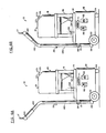
- steering handle 26 can be rotated 180 degrees, as shown in Figures 6A and 6B, to permit lifting eye 17 to project inwardly over center of gravity 188 of housing 12, reservoir support bracket 16 and reservoirs 18 and 20. This permits convenient lifting of the apparatus by a crane or other device at the construction site.
- Quick coupling fluid inlet connectors 34 and 36 are also attached to the top of the lid 14 and, respectively, connect fluid reservoirs 18 and 20 into the fluid flow system.
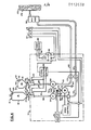
- FIG. 4 there is illustrated a schematic mechanical-electrical diagram of the multiple fluid mixing and dispensing apparatus 10 showing the items contained within housing 12 and their operation.
- disposable first reservoir 18 is connected in fluid communication with mixing head 50 through first coupling 34, conduit 52, first fluid pump 54, conduit 56, past pressure detector switch 58, conduit 59, first check valve 174, and finally through conduit 60.
- Disposable second fluid reservoir 20 is connected in fluid communication with mixing head 50 through second coupling 36, conduit 62, second fluid pump 64, conduit 65, check valve 176 and finally through conduit 66.
- First and second fluid pumps 54 and 64 are driven by a common drive motor 70 mechanically coupled to pumps 54 and 64 through an overload or torque releasable coupling 72 and a gear reduction system 74.
- Gear reduction system 74 is adapted to drive pump 64 at a predetermined reduced volume rate relative to pump 54.
- the gear ratio is adjusted to provide a pumping rate ratio that will give the correct aliquot proportioning of the two liquids necessary to achieve a complete chemical reaction after the mixed fluids leave the mixing head.
- pump size and speed must be properly selected. Because the curing agent, the material contained in disposable reservoir 20, has a low viscosity, and because the volume of the curing agent delivered is low, about one-half the volume of the resin material in reservoir 18, pump 64 is selected to have a low displacement and is adapted to be operated at a high speed. To provide good control the two pumps are driven at speeds inversely proportional to the respective viscosities of the fluids being pumped and at a predetermined ratio of fluid flow. Under these conditions, it has been found that pumping efficiency is greatly improved and ratioing of the fluid flow can be tightly controlled.
- a digital counter 71 is provided. Digital counter 71 is electrically connected to microswitch 73 which counts the number of revolutions of motor 70. Counter 71 is adapted to measure the total fluid flow in increments of 3.8 ccs. The operator can then record the amount of material delivered to each crack, keyway or port or he can tally the entire days volume of material used.
- torque release coupling 72 allows motor 70 to become disengaged from the pumps until the overload condition is corrected.
- Motor 70 is energized using power source 80 which is connected to the electrical system through disconnectable electrical connector 82 mounted on housing 12.
- disconnectable electrical connector 82 is electrically connected to ground or common 84, while the other side is first connected to "on-off" switch 86 and then in series to level detector control unit 88, pressure switch 58, motor speed control 90 and finally to pump drive motor 70. Electrically connected across "on-off” switch 86 is spring loaded, normally open, hand held switch 87. Switch 87 allows the operator to jog the injection pressure up slowly for sensitive pumping conditions requiring accurate control of injection pressure.
- the other side of motor 70 is, of course, electrically connected to ground or common 84.
- Pushbutton switch 61 Located adjacent hand held switch 87 is manually operated, normally open, pushbutton switch 61 which is electrically connected across pressure switch 58. Pushbutton switch 61 permits the operator to increase the injection pressure of the resin material above the setting of pressure switch 58 when the need arises.
- Level detector 88 further comprises a first fluid level sensor 96 disposed proximate coupling 34 and adapted to measure the fluid level immediately below that coupling.
- a second fluid level sensor 98 is disposed proximate coupling 36 and is adapted to neasure fluid level immediately below that coupling.
- One side each of the first fluid level sensor 96 and of the second fluid level sensor 98 are connected together, in common, to conductor 97, which is, in turn, connected to level detector control 88.
- the other side of first Eluid level sensor 96 is connected through conductor 39 back to level sensor control 88 as is the other side Of second fluid level sensor 98 through conductor 101.
- the disposable fluid reservoirs 18 and 20, typically, are used both for shipping the two-component resin materials to the point of use and also as dispensing reservoirs.
- Reservoir 18 comprises a generally transparent or translucent housing 19 having a bottom end 21 and a top end 29.
- a vent assembly 23 comprising a vent seal teat 25 and a cap receptacle 27.
- vent seal teat 25 is cut off to allow displacement air to enter housing 19, the shipping cap (not shown) that sealed top cap end 29 when the container was originally filled and shipped, is adapted to also fit on and be received by cap receptacle 27.
- seal vent assembly 23 can be sealed closed when reservoir 18 is removed from quick coupling 34 for storage as a partly filled container.
- a reservoir coupling member 25' is attached to cap end 29 to replace the shipping cap.
- Reservoir coupling member 25' is adapted to engage quick coupling 34 and is also provided with a shut-off valve 27 1 .
- valve 27' is closed and reservoir 18 is removed without spilling any of its contents. Reservoir 18 is then inverted to rest with bottom end 21 down.
- the original shipping cap (not shown) is attached to cap receptacle 27 prior to inverting the container to prevent loss of fluid from vent assembly 23.
- reservoir 20 also comprises a housing 31 having a bottom end 33 and a top cap end 35.
- a vent assembly 37 comprising a vent seal teat 39 and a cap receptacle 41.
- vent seal teat 39 When vent seal teat 39 is cut off, it will allow displacement air to enter housing 31.
- the shipping cap (not shown) that seals top end 35 during shipping, is adapted also to engage and be received by cap receptacle 39 and thus seal vent assembly 37 when reservoir 20 is removed from quick coupling 36 for storage as a partially filled container.
- a reservoir coupling member 43 is attached to cap end 35 to replace the shipping cap.
- Reservoir coupling member 43 is adapted to engage quick coupling 36 and is also provided with a valve 45.
- valve 45 When a partially emptied reservoir 20 is to be removed from quick coupling 36, valve 45 is closed, reservoir 20 is removed without spilling any of its contents and is then inverted to rest with bottom end 33 down.
- the original shipping cap is attached to cap receptacle 39 to prevent loss of fluid from vent assembly 37.
- the above described configuration permits disposable shipping reservoirs 18 and 20 to be connected directly to the apparatus without the need for field transfer of the adhesive components. This will prevent the introduction of contaminants into the pumping apparatus which would tend to accelerate wear of the pumping elements leading to severe damage and destruction of the pumps. Also, since the curing component of the epoxy adhesive system is hygroscopic, the use of the above-described configuration prevents water from contaminating the components, which would, in time, degrade the performance of the cured adhesive.
- both reservoirs 18 and 20 are transparent (or translucent), the operator can readily check the ratioing performance of the apparatus by comparing the levels and volumes of material in the containers. Further, the operator can detect contamination or incorrect material by the colour through the transparent or translucent wall of the container.
- Mixing head 50 comprises a body member 100, a first inlet port 102 adapted to receive conduit 60 conducting fluid from first disposable reservoir 18, a second inlet port 104 adapted to receive conduit 66 conducting fluid from second disposable reservoir 20, and outlet port 112 adapted to receive control nozzle 114.
- a set of mixing channels 106, 108 and 110 provides fluid communication between inlet ports 102-104 and outlet port 112.
- Control nozzle 114 comprises an inlet end 116 adapted to engage outlet port 112, a fluid flow control valve 118 and an outlet end 120.
- Mixing brushes 122, 124 and 126 are disposed in respective mixing channels.
- a first interconnecting port 130 is provided in the wall between the first two mixing channels distal inlet ports 102 and 104.
- a second interconnecting port 132 is located in the wall between the second and third channels distal first interconnecting port 130 and distal outlet port 112.
- a first plug 136 is adapted to threadably engage housing 100 at the end of the first channel proximate inlet port 102.
- Second plug 138 is also adapted threadably to engage housing 100 at the end of the first mixing channel proximate first interconnecting port 130 distal inlet port 102.
- Third end plug 140 is adapted threadably to engage housing 100 proximate second interconnecting port 132 while fourth plug 146 is adapted threadably to engage housing 100 at the opposite end of the second channel proximate the first interconnecting port 130.
- a fifth end plug 144 is adapted threadably to engage housing 100 at the lower end of the housing proximate the second interconnecting port 132, while sixth end plug 146 is adapted threadably to engage housing 100 proximate exit port 112.
- a first disposable reservoir 18 containing, typically, a reactive resin is connected to quick coupling 34 while a second fluid reservoir 20 containing, typically, an activator for the reactive resin, is connected to second quick connector coupling 36.
- switch 86 is operated to activate motor 70 through speed control 90.
- motor 70 is energized, first fluid pump 54 and second fluid pump 64 are actuated through gear reduction unit 74 to obtain a precise ratio of the flow of fluids from disposable container 18 relative to the fluid in disposable container 20. The fluid then simultaneously flows from disposable containers 18 and 20.
- fluid flowing from disposable reservoir 20 flows first past level dector 98, then through conduit 62, through pump 64, through conduit 65, through check valve 176, and conduit 66 to outlet port 104 ( Figure 5) and into mixing channel 106.
- the two mixing fluids then pass in and around bristles 154 of brush member 122 towards interconnecting port 130. They then travel down mixing channel 108, being blended and intermixed by bristles 158 of brush 124, then through second interconnecting port 132, and up through mixing channel 110 to be further intermixed by bristles 162 of brush 126.
- the fluid then passes out of mixing head housing 100 through outlet port 112, out through valve 118 and exit end 120 of nozzle 114.
- this particular apparatus is used to inject a polymerizable resin mixture into cracks in a concrete wall 130 for their repair.
- a self-adhesive tape having a width slightly larger than the diameter of nozzle outlet end 120, is placed to span across the crack at intervals along the crack approximately equal to the wall thickness.
- the crack is sealed with either a hot-melt adhesive or a two-component fast curing, epoxy adhesive 172.
- the material is puttied over the crack and allowed to harden.
- the strips of self-adhesive tape are removed prior to the hardening or setting up of adhesive 172. This leaves a series of small access ports along the crack length.
- the adhesive mixture from reservoirs 18 and 20 is then pumped into the crack by pressing nozzle end 120 against wall 170 at one of the openings created by the removed self-adhesive tape.
- "On-off" switch 86 Ls then actuated on the "On” position.
- the mixed adhesive material is then pumped into the crack until the resin mixture begins to appear at the next adjacent opening created when the self-adhesive tape was removed.
- Nozzle end 120 is then pressed against the crack at the next adjacent opening and the process repeated.
- a normally open, spring loaded, hand held switch 87 which is electrically connected across "on-off” switch 86, may be used by the operator to "jog” pump motor 70. By turning “on-off” switch 86 to the “off” or open position, hand held switch 87 can then be actuated to activate pump motor 70 to gradually raise the fluid pressure in steps. Pressure switch 58 will protect the system from fluid over-pressure during normal operation.
- the pressure at mixing head 50, in particular outlet end 120, must not be so high as to cause the fluid being injected into the crack to break the seal of the hot-melt or epoxy adhesive 132, placed over the crack on the surface of concrete wall 130.
- the pressure must also not be so low as to prevent, or appreciably decrease, the flow rate of fluids leaving exit end 120 of nozzle 114.
- a pressure switch 58 is located on the high pressure side of first pump 54 between conduits 56 and 59.
- a pressure switch could also be included in conduit 66 on the high pressure side of pump 64; however, the hydraulic pressure in each conduit would be approximately the same as the pressure at exit end 120 of nozzle 114 (not taking into account fluid friction). Thus only one pressure switch is really needed.
- Pressure switch 58 is, therefore, adjusted for the optimum pressure needed to meetthe requirements stated above.
- pressure switch 58 When pushbutton switch 61 is released, then pressure switch 58 will resume its function of de-energizing pump motor 70 until fluid pressure is reduced to below the pressure setting of pressure switch 58.
- a first level detector 96 is located proximate quick coupling 34 to detect an empty reservoir 18.
- a second level detector 98 is disposed proximate second quick coupling 36 to detect an empty disposable reservoir 20. If either reservoir 18 or 20 becomes empty, either detector 96 or 98, respectively, will be activated to actuate a disconnect relay (not shown) in level detector control 88. Since level detector control 88 is connected in series with speed control 90 and motor 70, motor 70 will become deactivated and pumping will stop.
- the multiple fluid mixing and dispensing apparatus 10 After the multiple fluid mixing and dispensing apparatus 10 has been used, it can be cleaned by pumping solvent through the conduit and pumping system with mixing head 50 being cleaned by removing plugs 138, 142 and 146 and then removing brushes 122, 124 and 126. Housing 100 can then be easily cleaned with a minimum of solvent. The brushes can be thrown away without cleaning.
- top end 29 of reservoir 18 is made to have a cap diameter different from that of the top end 35 of reservoir 20.
- a scale 51 is provided along the side of reservoir 18 whose graduations can be coordinated with the graduations of a similar scale 53 along the side of second reservoir 20.
- the scales can be either molded into the reservoir material itself or applied to the surface of the reservoir.
- the operating handle of Figures6A and 6B comprises, basically, a shaft portion 180, a curved portion 182 and a T-shaped handlebar 184.
- a lifting eye 17 is provided at the top of handle 26 to permit the apparatus to be lifted to the job site.
- a retaining pin 15 is also provided in bracket 28 to hold handle 26 in place while lifting and steering the apparatus.
- operating handle 26 is shown in its normal position when rolling the apparatus of the present invention about the job site.
- operating handle 26 has been rotated 180 degrees by removing retaining pin 15, rotating shaft 180 180 degrees in bracket 28 and then re-inserting pin 15 back through bracket 28 and shaft portion 180.
- lifting eye 17 is located directly over center of gravity 188 of the apparatus.
- the apparatus of the present invention can be lifted in an up-right position by a crane or other device and moved about the job site without causing spillage or leakage of fluids from the apparatus during such movement.
- reservoir support bracket 16 is adapted to be easily removable through the use of bolts or the like whereby housing 12, minus steering handle 26, reservoir 18 and 20, and reservoir support bracket 16, can pass through a small opening followed by the removed parts for simple assembly at the place of use.
Abstract
Description
- This invention relates generally to fluid dispensing apparatus, and, in particular, to apparatus for mixing and dispensing a plurality of different fluids.
- Devices used to pump two or more fluids to a mixing head where the fluids are sprayed onto a surface or injected into a cavity are relatively common.
- Some devices utilize independently driven fluid pumps in which the driving means is regulated to obtain a predetermined ratio of fluid volume flow and in which the pressure and temperature of the separate fluids are also monitored to ensure a uniformity of result.
- Other devices utilize various differing methods of obtaining a predetermined ratio of fluid volume being pumped. Some devices achieve this result by varying the orifice size of a venturi to vary the suction rate at which the fluids are withdrawn from their reservoirs. Other devices utilize piston and gear arrangements in the mixing head for metering the flow of fluid. Still other devices use several pumping cylinders of different volumes linked by an actuator arm simultaneously to pump fluids at a predetermined mix ratio.
- Other devices use positive displacement pumps having a fixed volume ratio; however, an adjustable length actuating arm is used to vary the ratio of stroke length, and therefore volume, when simultaneously pumping from their respective reservoirs.
- The apparatus of the present invention is an improvement over the prior art devices and is later illustrated as comprising a main housing enclosing first and second fluid pumps pumping fluid from first and second fluid reservoirs, respectively, mounted on top of the housing, to a mixing and dispensing head.
- According to the present invention there is provided apparatus for mixing and dispensing a fluid comprising a first fluid reservoir, a second fluid reservoir, a first fluid pump having an inlet port and an outlet port, said inlet port being in fluid communication with said first reservoir, a second fluid pump having an inlet port and an outlet port, said inlet port being in fluid communication with said second reservoir, means for driving said first and second pumpsat respective speeds inversely proportional to the respective viscosities of the fluids being pumped and at a predetermined ratio of fluid flow, said fluids being under generally the same pressure at the inlet ports of said first and second pumps, a power source electrically connected to said means for driving said first and second pumps, means mechanically connecting said first pump to said second pump for proportionally pumping fluid from said first and second reservoirs at a predetermined volume ratio, a mixing head, means for fluidly communicating said mixing head with said outlet port of said first pump, means for fluidly communicating said mixing head with said outlet port of said second pump, means for measuring fluid pressure of said fluid between said first pump and said mixing head, and means for electrically disconnecting said means for driving said first and second pumps when said fluid pressure exceeds a predetermined pressure and electrically connecting said power source to said means for driving said first and second pumps when said pressure is less than said predetermined pressure. Preferably means are provided for overriding said means for electrically disconnecting said means for driving said first and second pumps when said fluid pressure exceeds a predetermined pressure.
- Conveniently the apparatus can be mounted on a vehicle having a low centre of gravity and provided with a handle rotatable between a normal operative position and another position in which a lifting eye is vertically above the centre of gravity.
- The present invention will become further apparent from the following detailed description given by way of example with reference to the accompanying drawings, in which:-
- Figure 1 is an elevational side view of a multiple fluid mixing and dispensing apparatus embodying the present invention;
- Figure 2 is an elevational front view of the multiple fluid mixing and dispensing apparatus of Figure 1;
- Figure 3 is an elevational rear view of the multiple fluid mixing and dispensing apparatus of Figure 1;
- Figure 4 is a schematic mechanical-electrical diagram of the multiple fluid mixing and dispensing apparatus;
- Figure 5 is a partly cut-away view of a detail of the mixing head of the mixing and dispensing apparatus; and
- Figures 6A and 6B are detailed drawings illustrating the positioning of the operating handle and lifting eye relative to the centre of gravity of the apparatus.
- With reference to Figures 1, 2 and 3, there is illustrated, respectively, side, front and rear elevational views of an assembled multiple fluid mixing and dispensing
apparatus 10 comprising amain housing 12 containing the pumps and controls (not shown in Figures 1, 2 or 3) for pumping fluid to the mixing head (not shown in Figures 1, 2 or 3). - A
hinged lid 14 is connected proximate the top ofhousing 12. Asupport bracket 16, adapted to support a pair ofdisposable fluid reservoirs lid 14. - A pair of
wheels 22 are connected tohousing 12 proximate the rear thereof so that the apparatus can be conveniently moved about the job site. A pair oflevel supports 24 are attached to the underside ofhousing 12 proximate the front thereof to maintain the apparatus level during use and storage. - A
steering handle 26 is connected to the rear ofhousing 12 byhandle support brackets 28. A hose or fluidconduit support bracket 30 is attached tosteering handle 26 to supportfluid supply conduits - With particular reference to Figures 1 and 2, it will be noted that
steering handle 26 is removable fromhandle support bracket 28, being retained in position by retainingpin 15. In addition,steering handle 26 can be rotated 180 degrees, as shown in Figures 6A and 6B, to permit lifting eye 17 to project inwardly over center ofgravity 188 ofhousing 12,reservoir support bracket 16 andreservoirs - Quick coupling
fluid inlet connectors lid 14 and, respectively, connectfluid reservoirs - With reference to Figure 4, there is illustrated a schematic mechanical-electrical diagram of the multiple fluid mixing and dispensing
apparatus 10 showing the items contained withinhousing 12 and their operation. - In particular disposable
first reservoir 18 is connected in fluid communication with mixinghead 50 throughfirst coupling 34,conduit 52,first fluid pump 54,conduit 56, pastpressure detector switch 58,conduit 59,first check valve 174, and finally throughconduit 60. - Disposable
second fluid reservoir 20 is connected in fluid communication with mixinghead 50 throughsecond coupling 36, conduit 62, second fluid pump 64, conduit 65,check valve 176 and finally throughconduit 66. - First and
second fluid pumps 54 and 64, respectively, are driven by acommon drive motor 70 mechanically coupled topumps 54 and 64 through an overload or torquereleasable coupling 72 and a gear reduction system 74. - Gear reduction system 74 is adapted to drive pump 64 at a predetermined reduced volume rate relative to
pump 54. The gear ratio is adjusted to provide a pumping rate ratio that will give the correct aliquot proportioning of the two liquids necessary to achieve a complete chemical reaction after the mixed fluids leave the mixing head. - In typical gear pump design, two equal displacement pumps are driven at different speeds to secure the pumping ratio. However, it is well known that adhesive components, resin and hardener or curing agent, are typically of different viscosities. Since pumping efficiency goes down with viscosity, equal displacement pumps will not pump two components of different viscosities with equal efficiency. This leads to poor ratioing performance, particularly under low speed and high pressure conditions encountered when using the apparatus of the present invention. These speeds and pressures can range from 0-100 RPM and O-200 psi (O-13.78 bar), respectively.
- To ensure proper pump ratioing under all operating conditions, which may vary from 40 degrees F. to 110 degrees F. (4.4 to 43.3°C), pump size and speed must be properly selected. Because the curing agent, the material contained in
disposable reservoir 20, has a low viscosity, and because the volume of the curing agent delivered is low, about one-half the volume of the resin material inreservoir 18, pump 64 is selected to have a low displacement and is adapted to be operated at a high speed. To provide good control the two pumps are driven at speeds inversely proportional to the respective viscosities of the fluids being pumped and at a predetermined ratio of fluid flow. Under these conditions, it has been found that pumping efficiency is greatly improved and ratioing of the fluid flow can be tightly controlled. - Further, accurately to meter the volume of the fluid being pumped, a
digital counter 71 is provided.Digital counter 71 is electrically connected to microswitch 73 which counts the number of revolutions ofmotor 70.Counter 71 is adapted to measure the total fluid flow in increments of 3.8 ccs. The operator can then record the amount of material delivered to each crack, keyway or port or he can tally the entire days volume of material used. - In the event either pump becomes overloaded,
torque release coupling 72 allowsmotor 70 to become disengaged from the pumps until the overload condition is corrected. - Motor 70 is energized using
power source 80 which is connected to the electrical system through disconnectableelectrical connector 82 mounted onhousing 12. - One side of disconnectable
electrical connector 82 is electrically connected to ground or common 84, while the other side is first connected to "on-off"switch 86 and then in series to leveldetector control unit 88,pressure switch 58,motor speed control 90 and finally to pumpdrive motor 70. Electrically connected across "on-off"switch 86 is spring loaded, normally open, hand heldswitch 87.Switch 87 allows the operator to jog the injection pressure up slowly for sensitive pumping conditions requiring accurate control of injection pressure. The other side ofmotor 70 is, of course, electrically connected to ground or common 84. - Located adjacent hand held
switch 87 is manually operated, normally open,pushbutton switch 61 which is electrically connected acrosspressure switch 58.Pushbutton switch 61 permits the operator to increase the injection pressure of the resin material above the setting ofpressure switch 58 when the need arises. -
Level detector 88 further comprises a firstfluid level sensor 96 disposed proximate coupling 34 and adapted to measure the fluid level immediately below that coupling. A secondfluid level sensor 98 is disposedproximate coupling 36 and is adapted to neasure fluid level immediately below that coupling. One side each of the firstfluid level sensor 96 and of the secondfluid level sensor 98 are connected together, in common, to conductor 97, which is, in turn, connected tolevel detector control 88. The other side of first Eluidlevel sensor 96 is connected throughconductor 39 back tolevel sensor control 88 as is the other side Of secondfluid level sensor 98 throughconductor 101. - The
disposable fluid reservoirs -
Reservoir 18 comprises a generally transparent ortranslucent housing 19 having abottom end 21 and atop end 29. Proximate thebottom end 21 ofreservoir 18 is avent assembly 23 comprising avent seal teat 25 and acap receptacle 27. Whenvent seal teat 25 is cut off to allow displacement air to enterhousing 19, the shipping cap (not shown) that sealedtop cap end 29 when the container was originally filled and shipped, is adapted to also fit on and be received bycap receptacle 27. Thus sealvent assembly 23 can be sealed closed whenreservoir 18 is removed fromquick coupling 34 for storage as a partly filled container. - When the shipping cap (not shown) is removed from the
top cap end 29, a reservoir coupling member 25' is attached to capend 29 to replace the shipping cap. Reservoir coupling member 25' is adapted to engagequick coupling 34 and is also provided with a shut-offvalve 271. When a partially emptied reservoir is to be removed fromquick coupling 34, valve 27' is closed andreservoir 18 is removed without spilling any of its contents.Reservoir 18 is then inverted to rest withbottom end 21 down. The original shipping cap (not shown) is attached to capreceptacle 27 prior to inverting the container to prevent loss of fluid fromvent assembly 23. - In a like manner,
reservoir 20 also comprises ahousing 31 having abottom end 33 and atop cap end 35. Proximatebottom end 33 ofhousing 31 is avent assembly 37 comprising avent seal teat 39 and acap receptacle 41. - When
vent seal teat 39 is cut off, it will allow displacement air to enterhousing 31. The shipping cap (not shown) that sealstop end 35 during shipping, is adapted also to engage and be received bycap receptacle 39 and thus sealvent assembly 37 whenreservoir 20 is removed fromquick coupling 36 for storage as a partially filled container. - When the shipping cap (not shown) is removed from
cap end 35, areservoir coupling member 43 is attached to capend 35 to replace the shipping cap.Reservoir coupling member 43 is adapted to engagequick coupling 36 and is also provided with avalve 45. - When a partially emptied
reservoir 20 is to be removed fromquick coupling 36,valve 45 is closed,reservoir 20 is removed without spilling any of its contents and is then inverted to rest withbottom end 33 down. The original shipping cap is attached to capreceptacle 39 to prevent loss of fluid fromvent assembly 37. - The above described configuration permits
disposable shipping reservoirs - Because both
reservoirs - Because construction sites and other areas where the apparatus of the present invention is used are generally dirty with various air-borne contaminants such as dust and chemical vapors, the use of the shipping container as the reservoir reduces the possibility of introducing such contaminants into the system to cause the pumps to become eroded and corroded, thus reducing their close ratioing performance.
- With reference to Figure 5, there is illustrated a partial cut-away view of mixing
head 50 showing its internal construction. - Mixing
head 50 comprises abody member 100, afirst inlet port 102 adapted to receiveconduit 60 conducting fluid from firstdisposable reservoir 18, asecond inlet port 104 adapted to receiveconduit 66 conducting fluid from seconddisposable reservoir 20, andoutlet port 112 adapted to receivecontrol nozzle 114. A set of mixingchannels outlet port 112. -
Control nozzle 114 comprises an inlet end 116 adapted to engageoutlet port 112, a fluidflow control valve 118 and anoutlet end 120. Mixing brushes 122, 124 and 126 are disposed in respective mixing channels. - A first interconnecting port 130 is provided in the wall between the first two mixing channels
distal inlet ports second interconnecting port 132 is located in the wall between the second and third channels distal first interconnecting port 130 anddistal outlet port 112. - A
first plug 136 is adapted to threadably engagehousing 100 at the end of the first channelproximate inlet port 102.Second plug 138 is also adapted threadably to engagehousing 100 at the end of the first mixing channel proximate first interconnecting port 130distal inlet port 102. -
Third end plug 140 is adapted threadably to engagehousing 100 proximatesecond interconnecting port 132 whilefourth plug 146 is adapted threadably to engagehousing 100 at the opposite end of the second channel proximate the first interconnecting port 130. - A
fifth end plug 144 is adapted threadably to engagehousing 100 at the lower end of the housing proximate thesecond interconnecting port 132, whilesixth end plug 146 is adapted threadably to engagehousing 100proximate exit port 112. - Thus it can be seen that the two fluids flowing from
inlet ports bristles 154 ofbrush 127 as it passes up the first mixing channel towards first interconnecting port 130. As the fluid continues its flow, as indicated byarrow 156, bristles 158 of brush 124 will continue to cause the fluids to become more intimately mixed as they travel towards second interconnectingport 132. - The same is true as the fluids flow in accordance with
arrow 160 up thethird mixing channel 110 to be finally mixed bybristles 162 ofbrush 126 and then flow out ofexit port 112 throughvalve 118 and outlet end 120 ofnozzle 114. - To operate the multiple mixing and dispensing apparatus a first
disposable reservoir 18 containing, typically, a reactive resin, is connected toquick coupling 34 while asecond fluid reservoir 20 containing, typically, an activator for the reactive resin, is connected to secondquick connector coupling 36. Afterpower source 80 is connected to plug 82,switch 86 is operated to activatemotor 70 throughspeed control 90. Whenmotor 70 is energized,first fluid pump 54 and second fluid pump 64 are actuated through gear reduction unit 74 to obtain a precise ratio of the flow of fluids fromdisposable container 18 relative to the fluid indisposable container 20. The fluid then simultaneously flows fromdisposable containers container 18 the fluid flows firstpast level detector 96, then throughconduit 52, throughpump 54 andconduit 56past pressure switch 58 intoconduit 59, throughcheck valve 174, throughconduit 60 and finally to mixinghead 50. In mixinghead 50 it is intermixed and blended with the second fluid finally to flow out of exit port 102 (Figure 5) into mixingchannel 106. - In similar manner, fluid flowing from
disposable reservoir 20 flows firstpast level dector 98, then through conduit 62, through pump 64, through conduit 65, throughcheck valve 176, andconduit 66 to outlet port 104 (Figure 5) and into mixingchannel 106. - The two mixing fluids then pass in and around bristles 154 of
brush member 122 towards interconnecting port 130. They then travel down mixingchannel 108, being blended and intermixed bybristles 158 of brush 124, then through second interconnectingport 132, and up through mixingchannel 110 to be further intermixed bybristles 162 ofbrush 126. - The fluid then passes out of mixing
head housing 100 throughoutlet port 112, out throughvalve 118 and exit end 120 ofnozzle 114. - Normally, this particular apparatus is used to inject a polymerizable resin mixture into cracks in a concrete wall 130 for their repair.
- J To repair a crack in
concrete wall 170, a self-adhesive tape, having a width slightly larger than the diameter ofnozzle outlet end 120, is placed to span across the crack at intervals along the crack approximately equal to the wall thickness. - Between successive tapes, the crack is sealed with either a hot-melt adhesive or a two-component fast curing,
epoxy adhesive 172. The material is puttied over the crack and allowed to harden. - The strips of self-adhesive tape are removed prior to the hardening or setting up of
adhesive 172. This leaves a series of small access ports along the crack length. The adhesive mixture fromreservoirs nozzle end 120 againstwall 170 at one of the openings created by the removed self-adhesive tape. "On-off"switch 86 Ls then actuated on the "On" position. The mixed adhesive material is then pumped into the crack until the resin mixture begins to appear at the next adjacent opening created when the self-adhesive tape was removed. -
Nozzle end 120 is then pressed against the crack at the next adjacent opening and the process repeated. - In order to achieve a controlled rate of increase in pressure of the fluid being injected into the crack, a normally open, spring loaded, hand held
switch 87, which is electrically connected across "on-off"switch 86, may be used by the operator to "jog"pump motor 70. By turning "on-off"switch 86 to the "off" or open position, hand heldswitch 87 can then be actuated to activatepump motor 70 to gradually raise the fluid pressure in steps.Pressure switch 58 will protect the system from fluid over-pressure during normal operation. - The pressure at mixing
head 50, inparticular outlet end 120, must not be so high as to cause the fluid being injected into the crack to break the seal of the hot-melt orepoxy adhesive 132, placed over the crack on the surface of concrete wall 130. The pressure must also not be so low as to prevent, or appreciably decrease, the flow rate of fluids leavingexit end 120 ofnozzle 114. - To prevent such an occurrence, a
pressure switch 58 is located on the high pressure side offirst pump 54 betweenconduits conduit 66 on the high pressure side of pump 64; however, the hydraulic pressure in each conduit would be approximately the same as the pressure atexit end 120 of nozzle 114 (not taking into account fluid friction). Thus only one pressure switch is really needed. -
Pressure switch 58 is, therefore, adjusted for the optimum pressure needed to meetthe requirements stated above. - Under certain circumstances, it may be necessary to inject the fluid mixture out of mixing
head 50 at a higher pressure than the pressure setting ofpressure switch 58. This would occur, typically, for very fine cracks or where debris in the crack prevents the rapid flow of fluid into the full volume and depth of the crack. - Under these circumstances, the operator can depress normally open,
pushbutton switch 61 which is electrically connected acrosspressure switch 58. This action will temporarily short outpressure switch 58 and allowpump motor 70 to continue pumping should the fluid pressure exceed the pressure setting ofpressure switch 58. - When
pushbutton switch 61 is released, then pressure switch 58 will resume its function of de-energizingpump motor 70 until fluid pressure is reduced to below the pressure setting ofpressure switch 58. - Where a polymerizing resin is being injected into a crack in concrete, it is important that there be a correct mixture of the two resins, otherwise the material will fail to harden and there will be no binding of the two sides of the crack to each other to create a monolithic whole. This usually occurs where there is single component pumping.
- To prevent this deficiency, a
first level detector 96 is located proximatequick coupling 34 to detect anempty reservoir 18. Asecond level detector 98 is disposed proximate secondquick coupling 36 to detect an emptydisposable reservoir 20. If eitherreservoir detector level detector control 88. Sincelevel detector control 88 is connected in series withspeed control 90 andmotor 70,motor 70 will become deactivated and pumping will stop. - After the multiple fluid mixing and dispensing
apparatus 10 has been used, it can be cleaned by pumping solvent through the conduit and pumping system with mixinghead 50 being cleaned by removingplugs brushes - In order to prevent inadvertent switching of the two reservoirs with the resultant wrong mixing of the two fluids,
top end 29 ofreservoir 18 is made to have a cap diameter different from that of thetop end 35 ofreservoir 20. - Also, in order to permit an operator to monitor the proper proportioning of the fluids being pumped, a scale 51 is provided along the side of
reservoir 18 whose graduations can be coordinated with the graduations of asimilar scale 53 along the side ofsecond reservoir 20. The scales can be either molded into the reservoir material itself or applied to the surface of the reservoir. - With respect to Figures 6A and 6B, there is illustrated a more detailed drawing of the positioning of the operating handle 26 relative to
main housing 12. The operating handle of Figures6A and 6B comprises, basically, ashaft portion 180, acurved portion 182 and a T-shapedhandlebar 184. - In addition, a lifting eye 17 is provided at the top of
handle 26 to permit the apparatus to be lifted to the job site. - A retaining
pin 15 is also provided inbracket 28 to holdhandle 26 in place while lifting and steering the apparatus. - In Figure 6A, operating
handle 26 is shown in its normal position when rolling the apparatus of the present invention about the job site. - In Figure 6B, operating
handle 26 has been rotated 180 degrees by removing retainingpin 15,rotating shaft 180 180 degrees inbracket 28 and then re-insertingpin 15 back throughbracket 28 andshaft portion 180. - As shown in Figure 6B, lifting eye 17 is located directly over center of
gravity 188 of the apparatus. Thus, the apparatus of the present invention can be lifted in an up-right position by a crane or other device and moved about the job site without causing spillage or leakage of fluids from the apparatus during such movement. - Further, where a restricted entrance limits movement of the apparatus to its place of use,
reservoir support bracket 16 is adapted to be easily removable through the use of bolts or the like wherebyhousing 12, minus steeringhandle 26,reservoir reservoir support bracket 16, can pass through a small opening followed by the removed parts for simple assembly at the place of use.
Claims (10)
Priority Applications (1)
| Application Number | Priority Date | Filing Date | Title |
|---|---|---|---|
| AT83306974T ATE45298T1 (en) | 1982-11-30 | 1983-11-15 | DEVICE FOR MIXING AND DISTRIBUTING SEVERAL DIFFERENT FLUIDS. |
Applications Claiming Priority (2)
| Application Number | Priority Date | Filing Date | Title |
|---|---|---|---|
| US06/445,840 US4789100A (en) | 1980-11-04 | 1982-11-30 | Multiple fluid pumping system |
| US445840 | 1982-11-30 |
Publications (3)
| Publication Number | Publication Date |
|---|---|
| EP0112638A2 true EP0112638A2 (en) | 1984-07-04 |
| EP0112638A3 EP0112638A3 (en) | 1986-11-26 |
| EP0112638B1 EP0112638B1 (en) | 1989-08-09 |
Family
ID=23770400
Family Applications (1)
| Application Number | Title | Priority Date | Filing Date |
|---|---|---|---|
| EP83306974A Expired EP0112638B1 (en) | 1982-11-30 | 1983-11-15 | Apparatus for mixing and dispensing a plurality of different fluids |
Country Status (5)
| Country | Link |
|---|---|
| US (1) | US4789100A (en) |
| EP (1) | EP0112638B1 (en) |
| AT (1) | ATE45298T1 (en) |
| DE (1) | DE3380345D1 (en) |
| SG (1) | SG65892G (en) |
Cited By (20)
| Publication number | Priority date | Publication date | Assignee | Title |
|---|---|---|---|---|
| EP0387978A2 (en) * | 1989-03-13 | 1990-09-19 | Behr Industrial Equipment Inc. | Electrostatic spray coating apparatus for applying two component mixture |
| WO1992000138A1 (en) * | 1990-06-22 | 1992-01-09 | Fosroc International Limited | Apparatus for delivering a rapidly setting composition |
| EP0945171A2 (en) * | 1998-03-27 | 1999-09-29 | Dow Corning Corporation | Method of metering a liquid additive into a liquid silicon-containing material |
| EP1331072A1 (en) * | 2002-01-28 | 2003-07-30 | ELAST Kunststofftechnik GmbH & Co. KEG | Process and apparatus for the controlled removal of fluent materials from several receptacles |
| US7757896B2 (en) | 2006-03-06 | 2010-07-20 | The Coca-Cola Company | Beverage dispensing system |
| WO2011008390A1 (en) * | 2009-07-17 | 2011-01-20 | Illinois Tool Works Inc. | Metering system with variable volumes |
| US7913879B2 (en) | 2006-03-06 | 2011-03-29 | The Coca-Cola Company | Beverage dispensing system |
| US8162176B2 (en) | 2007-09-06 | 2012-04-24 | The Coca-Cola Company | Method and apparatuses for providing a selectable beverage |
| US8251258B2 (en) | 2007-09-06 | 2012-08-28 | The Coca-Cola Company | Systems and methods of selecting and dispensing products |
| US8551562B2 (en) | 2009-07-17 | 2013-10-08 | Illnois Tool Works Inc. | Method for metering hot melt adhesives with variable adhesive volumes |
| US8960500B2 (en) | 2006-03-06 | 2015-02-24 | The Coca-Cola Company | Dispenser for beverages including juices |
| US9034425B2 (en) | 2012-04-11 | 2015-05-19 | Nordson Corporation | Method and apparatus for applying adhesive on an elastic strand in a personal disposable hygiene product |
| US9415992B2 (en) | 2006-03-06 | 2016-08-16 | The Coca-Cola Company | Dispenser for beverages having a rotary micro-ingredient combination chamber |
| US9573159B2 (en) | 2009-08-31 | 2017-02-21 | Illinois Tool Works, Inc. | Metering system for simultaneously dispensing two different adhesives from a single metering device or applicator onto a common substrate |
| US9682392B2 (en) | 2012-04-11 | 2017-06-20 | Nordson Corporation | Method for applying varying amounts or types of adhesive on an elastic strand |
| US9718081B2 (en) | 2009-08-31 | 2017-08-01 | Illinois Tool Works Inc. | Metering system for simultaneously dispensing two different adhesives from a single metering device or applicator onto a common substrate |
| US9821992B2 (en) | 2006-03-06 | 2017-11-21 | The Coca-Cola Company | Juice dispensing system |
| EP2364952B1 (en) * | 2002-11-04 | 2017-12-20 | Graco Minnesota Inc. | Fast set material proportioner |
| US10280060B2 (en) | 2006-03-06 | 2019-05-07 | The Coca-Cola Company | Dispenser for beverages having an ingredient mixing module |
| US10631558B2 (en) | 2006-03-06 | 2020-04-28 | The Coca-Cola Company | Methods and apparatuses for making compositions comprising an acid and an acid degradable component and/or compositions comprising a plurality of selectable components |
Families Citing this family (58)
| Publication number | Priority date | Publication date | Assignee | Title |
|---|---|---|---|---|
| US5004159A (en) * | 1988-01-25 | 1991-04-02 | Specified Equipment Systems Company, Inc. | Method and apparatus for applying single of multicomponent materials |
| US5005765A (en) * | 1988-01-25 | 1991-04-09 | Specified Equipment Systems Company, Inc. | Method and apparatus for applying multicomponent materials |
| US4878454A (en) * | 1988-09-16 | 1989-11-07 | Behr Industrial Equipment Inc. | Electrostatic painting apparatus having optically sensed flow meter |
| US5064120A (en) * | 1989-11-29 | 1991-11-12 | Luttrell Jr Noel E | Fiberglass spray-up apparatus having display of cumulative amount of material dispensed |
| DE4023923A1 (en) * | 1990-07-27 | 1992-01-30 | Klaus Wasmer | Reagents mixer for making floor coatings - is mobile appts. with reagent tanks, metering devices, outlets to mixing container and movable stirrer to enter reagents or mix |
| US5190373A (en) * | 1991-12-24 | 1993-03-02 | Union Carbide Chemicals & Plastics Technology Corporation | Method, apparatus, and article for forming a heated, pressurized mixture of fluids |
| DE4225072C2 (en) * | 1992-07-29 | 1996-08-29 | Wagner Gmbh J | Method for protecting and stopping a motor-driven pressure generator pump for a coating device and device for carrying out the method |
| US5687779A (en) * | 1992-09-17 | 1997-11-18 | Tetra Laval Holdings & Finance S.A. | Packaging machine system for filling primary and secondary products into a container |
| CA2107523C (en) * | 1993-10-01 | 2004-05-04 | Gary D. Langeman | Plural component delivery system |
| US5570839A (en) * | 1994-01-31 | 1996-11-05 | Glas-Craft, Inc. | Plural component flow monitoring system |
| US5556009A (en) * | 1994-07-18 | 1996-09-17 | Wagner Spray Tech Corporation | Adjustable constant pressure caulk gun |
| US5671889A (en) * | 1995-02-17 | 1997-09-30 | Petty; Ralph S. | Waterproofing spray apparatus |
| US6095371A (en) * | 1996-02-21 | 2000-08-01 | Cassiano Limited | Method and apparatus for adding fluid additives to fluids |
| US5857589A (en) * | 1996-11-20 | 1999-01-12 | Fluid Research Corporation | Method and apparatus for accurately dispensing liquids and solids |
| US5810254A (en) * | 1996-12-31 | 1998-09-22 | Illnois Tool Works, Inc. | Low pressure polyurethane spraying assembly |
| US5979793A (en) * | 1997-06-04 | 1999-11-09 | Louis; R. J. | Self-contained misting device |
| US6044875A (en) * | 1997-07-21 | 2000-04-04 | Tetra Laval Holdings & Finance, S.A. | Dual chamber product tank for dual stream filling system |
| US5829476A (en) * | 1997-07-21 | 1998-11-03 | Tetra Laval Holdings & Finance, Sa | Dual-stream filling valve |
| US5992686A (en) * | 1998-02-27 | 1999-11-30 | Fluid Research Corporation | Method and apparatus for dispensing liquids and solids |
| WO1999062328A1 (en) * | 1998-06-03 | 1999-12-09 | Louis R J | Self-contained misting device |
| DE19903825A1 (en) * | 1999-02-02 | 2000-08-24 | Daimler Chrysler Ag | Lacquer leakage supervision system for lacquering plant, comparing lacquer quantity taken from reservoir in data processing unit with lacquer quantity leaving lacquer pulverize |
| US20020139867A1 (en) * | 2001-03-28 | 2002-10-03 | Bulloch Ron C. | Volumetric inductor/eductor |
| US20030080203A1 (en) * | 2001-10-30 | 2003-05-01 | Jay Roth | Apparatus and method for combining liquids and fillers for spray application |
| US6814110B2 (en) * | 2002-12-12 | 2004-11-09 | Stainless Steel Coatings, Inc. | Method of and apparatus for improved pressurized fluid dispensing for the guaranteed filling of cavities and/or the generating of guaranteed uniform gasket beads and the like |
| US6929153B1 (en) * | 2003-03-19 | 2005-08-16 | Horst Gerich | Fluid dispensing apparatus with check-valve operated mixing ability |
| US20040186621A1 (en) * | 2003-03-19 | 2004-09-23 | Nordson Corporation | Method of implementing multiple pump speeds for dispensing a viscous material |
| US7807118B2 (en) * | 2004-09-07 | 2010-10-05 | Tristel Plc | Decontamination system |
| US20060051285A1 (en) * | 2004-09-07 | 2006-03-09 | The Tristel Company Limited | Chlorine dioxide generation |
| US8642054B2 (en) * | 2004-09-07 | 2014-02-04 | Tristel Plc | Sterilant system |
| US7350672B1 (en) | 2004-09-30 | 2008-04-01 | Horst Gerich | Fluid dispensing apparatus |
| US20060086826A1 (en) * | 2004-10-07 | 2006-04-27 | Impact Composite Technology, Ltd. | Filler injector system for spray layup |
| US20070000947A1 (en) * | 2005-07-01 | 2007-01-04 | Lewis Russell H | Apparatus and methods for dispensing fluidic or viscous materials |
| US20070069040A1 (en) * | 2005-08-15 | 2007-03-29 | Lewis Russell H | Apparatus and methods for dispensing fluidic or viscous materials |
| US20070131794A1 (en) * | 2005-12-12 | 2007-06-14 | Shin-Bing Lai | Multifunction spray gun |
| US8739840B2 (en) | 2010-04-26 | 2014-06-03 | The Coca-Cola Company | Method for managing orders and dispensing beverages |
| US8342372B2 (en) * | 2006-06-15 | 2013-01-01 | Handy & Harman | Adhesive dispenser system |
| US8167170B2 (en) | 2006-06-15 | 2012-05-01 | Handy & Harman | Adhesive dispenser system |
| US8251603B2 (en) * | 2007-03-12 | 2012-08-28 | John Kott | Pressure fed squeege applicator |
| US20090068034A1 (en) * | 2007-09-12 | 2009-03-12 | Pumptec, Inc. | Pumping system with precise ratio output |
| US8584973B2 (en) * | 2007-10-31 | 2013-11-19 | Nordson Corporation | Powder coating gun with manually operated controls on gun |
| US9566594B2 (en) | 2010-02-18 | 2017-02-14 | Adco Products, Llc | Adhesive applicator |
| US9174234B2 (en) | 2010-02-18 | 2015-11-03 | Adco Products, Llc | Method of applying a polyurethane adhesive to a substrate |
| WO2011103094A2 (en) * | 2010-02-18 | 2011-08-25 | Adco Products, Inc. | Multi-bead applicator |
| US9089869B2 (en) | 2010-02-18 | 2015-07-28 | Adco Products, Llc | Adhesive bead applicator |
| US10239087B2 (en) * | 2010-02-18 | 2019-03-26 | Adco Products, Llc | Multi-bead applicator |
| US8757222B2 (en) | 2010-04-26 | 2014-06-24 | The Coca-Cola Company | Vessel activated beverage dispenser |
| US9670919B2 (en) * | 2010-11-18 | 2017-06-06 | Wagner Spray Tech Corporation | Plural component pumping system |
| US9381536B2 (en) | 2011-12-28 | 2016-07-05 | Adco Products, Llc | Multi-bead applicator |
| US9316216B1 (en) * | 2012-03-28 | 2016-04-19 | Pumptec, Inc. | Proportioning pump, control systems and applicator apparatus |
| US9499390B1 (en) * | 2012-07-17 | 2016-11-22 | Global Agricultural Technology And Engineering, Llc | Liquid delivery system |
| US9242267B2 (en) * | 2013-01-31 | 2016-01-26 | Owens Corning Intellectual Capital, Llc | Method and apparatus for mixing and applying material |
| US9895708B2 (en) * | 2014-10-20 | 2018-02-20 | Akurate Dynamics LLC | System for dispensing multiple component chemical sprays |
| US10035168B1 (en) * | 2015-10-21 | 2018-07-31 | Horst Gerich | Low pressure two component fluid metering, mixing and dispensing system |
| US10760557B1 (en) | 2016-05-06 | 2020-09-01 | Pumptec, Inc. | High efficiency, high pressure pump suitable for remote installations and solar power sources |
| US10823160B1 (en) | 2017-01-12 | 2020-11-03 | Pumptec Inc. | Compact pump with reduced vibration and reduced thermal degradation |
| EP3768415A4 (en) * | 2018-03-22 | 2021-12-08 | Eran Zagorsky | Dispenser for binary viscous fluids with aggregate |
| GB2582996B (en) * | 2019-07-01 | 2021-04-14 | A2E Industries Ltd | Vehicle, apparatus and method |
| AU2020102019B4 (en) * | 2020-06-02 | 2021-02-25 | Total Coolant Management Solutions Pty Ltd | Mobile liquid blending apparatus |
Citations (6)
| Publication number | Priority date | Publication date | Assignee | Title |
|---|---|---|---|---|
| DE2012337A1 (en) * | 1970-03-16 | 1971-10-07 | Dudda U | Plastics mixer and dispenser |
| DE2806050A1 (en) * | 1978-02-14 | 1979-08-16 | Durol Gmbh & Co Kg Chem Fab Er | Continuously mixing two viscous reagents - pressurised reagents flowing to alternate ends of two cylinders with linked pistons |
| US4171191A (en) * | 1976-03-25 | 1979-10-16 | Krueger Wallace F | Apparatus for transferring metered quantities of material from one location to another |
| DE2925479A1 (en) * | 1979-06-23 | 1981-01-15 | Elastogran Gmbh | Liquid plastic components metering plant - with metering units and hydraulic power pack mounted on oil tank carrier structure |
| EP0026874A1 (en) * | 1979-10-05 | 1981-04-15 | Elastogran Maschinenbau GmbH & Co. | Device for comparison measurement and regulation of the flow of ingredients in mixing apparatuses for multicomponent plastics |
| EP0059380A2 (en) * | 1981-03-04 | 1982-09-08 | Hutter, Charles George, III | System for dispensing curable compositions |
Family Cites Families (13)
| Publication number | Priority date | Publication date | Assignee | Title |
|---|---|---|---|---|
| US3104824A (en) * | 1963-09-24 | Coating apparatus | ||
| US2608439A (en) * | 1949-04-01 | 1952-08-26 | Ernest N Bates | Liquid spray device |
| US2819928A (en) * | 1954-05-18 | 1958-01-14 | Atlas Copco Ab | Apparatus for simultaneously discharging materials |
| US3008808A (en) * | 1958-07-21 | 1961-11-14 | William C Hodges | Coating applicator for dispensing chemically reactive materials |
| US3079090A (en) * | 1959-04-27 | 1963-02-26 | Herman W Decker | Method and apparatus for applying liquids |
| US3067987A (en) * | 1959-06-19 | 1962-12-11 | Grace W R & Co | Two-component mixer |
| US3097764A (en) * | 1960-02-09 | 1963-07-16 | Union Carbide Corp | Proportioning system |
| US3207378A (en) * | 1961-08-23 | 1965-09-21 | Pyles Ind Inc | Metering pump assembly |
| US3223040A (en) * | 1962-04-09 | 1965-12-14 | Stewart Warner Corp | Two component pumping and proportioning system |
| US3263932A (en) * | 1963-12-23 | 1966-08-02 | Timpte Inc | Liquid proportioning apparatus |
| US3298383A (en) * | 1964-03-23 | 1967-01-17 | Phillips Petroleum Co | Fluid blending system |
| US3393834A (en) * | 1966-01-28 | 1968-07-23 | Dow Chemical Co | Apparatus for the preparation of fiber reinforced plastics |
| US4169545A (en) * | 1977-08-01 | 1979-10-02 | Ransburg Corporation | Plural component dispensing apparatus |
-
1982
- 1982-11-30 US US06/445,840 patent/US4789100A/en not_active Expired - Lifetime
-
1983
- 1983-11-15 DE DE8383306974T patent/DE3380345D1/en not_active Expired
- 1983-11-15 EP EP83306974A patent/EP0112638B1/en not_active Expired
- 1983-11-15 AT AT83306974T patent/ATE45298T1/en not_active IP Right Cessation
-
1992
- 1992-06-30 SG SG658/92A patent/SG65892G/en unknown
Patent Citations (6)
| Publication number | Priority date | Publication date | Assignee | Title |
|---|---|---|---|---|
| DE2012337A1 (en) * | 1970-03-16 | 1971-10-07 | Dudda U | Plastics mixer and dispenser |
| US4171191A (en) * | 1976-03-25 | 1979-10-16 | Krueger Wallace F | Apparatus for transferring metered quantities of material from one location to another |
| DE2806050A1 (en) * | 1978-02-14 | 1979-08-16 | Durol Gmbh & Co Kg Chem Fab Er | Continuously mixing two viscous reagents - pressurised reagents flowing to alternate ends of two cylinders with linked pistons |
| DE2925479A1 (en) * | 1979-06-23 | 1981-01-15 | Elastogran Gmbh | Liquid plastic components metering plant - with metering units and hydraulic power pack mounted on oil tank carrier structure |
| EP0026874A1 (en) * | 1979-10-05 | 1981-04-15 | Elastogran Maschinenbau GmbH & Co. | Device for comparison measurement and regulation of the flow of ingredients in mixing apparatuses for multicomponent plastics |
| EP0059380A2 (en) * | 1981-03-04 | 1982-09-08 | Hutter, Charles George, III | System for dispensing curable compositions |
Cited By (37)
| Publication number | Priority date | Publication date | Assignee | Title |
|---|---|---|---|---|
| EP0387978A2 (en) * | 1989-03-13 | 1990-09-19 | Behr Industrial Equipment Inc. | Electrostatic spray coating apparatus for applying two component mixture |
| EP0387978A3 (en) * | 1989-03-13 | 1991-10-02 | Behr Industrial Equipment Inc. | Electrostatic spray coating apparatus for applying two component mixture |
| WO1992000138A1 (en) * | 1990-06-22 | 1992-01-09 | Fosroc International Limited | Apparatus for delivering a rapidly setting composition |
| US5320424A (en) * | 1990-06-22 | 1994-06-14 | Fosroc International Ltd. | Apparatus for delivering a rapidly setting composition |
| EP0945171A2 (en) * | 1998-03-27 | 1999-09-29 | Dow Corning Corporation | Method of metering a liquid additive into a liquid silicon-containing material |
| EP0945171A3 (en) * | 1998-03-27 | 2001-03-28 | Dow Corning Corporation | Method of metering a liquid additive into a liquid silicon-containing material |
| EP1331072A1 (en) * | 2002-01-28 | 2003-07-30 | ELAST Kunststofftechnik GmbH & Co. KEG | Process and apparatus for the controlled removal of fluent materials from several receptacles |
| EP2364952B1 (en) * | 2002-11-04 | 2017-12-20 | Graco Minnesota Inc. | Fast set material proportioner |
| US10631560B2 (en) | 2006-03-06 | 2020-04-28 | The Coca-Cola Company | Methods and apparatuses for making compositions comprising an acid and an acid degradable component and/or compositions comprising a plurality of selectable components |
| US7913879B2 (en) | 2006-03-06 | 2011-03-29 | The Coca-Cola Company | Beverage dispensing system |
| US8162181B2 (en) | 2006-03-06 | 2012-04-24 | The Coca-Cola Company | Beverage dispensing system |
| US10631558B2 (en) | 2006-03-06 | 2020-04-28 | The Coca-Cola Company | Methods and apparatuses for making compositions comprising an acid and an acid degradable component and/or compositions comprising a plurality of selectable components |
| US10280060B2 (en) | 2006-03-06 | 2019-05-07 | The Coca-Cola Company | Dispenser for beverages having an ingredient mixing module |
| US10029904B2 (en) | 2006-03-06 | 2018-07-24 | The Coca-Cola Company | Beverage dispensing system |
| US7757896B2 (en) | 2006-03-06 | 2010-07-20 | The Coca-Cola Company | Beverage dispensing system |
| US9821992B2 (en) | 2006-03-06 | 2017-11-21 | The Coca-Cola Company | Juice dispensing system |
| US9415992B2 (en) | 2006-03-06 | 2016-08-16 | The Coca-Cola Company | Dispenser for beverages having a rotary micro-ingredient combination chamber |
| US8960500B2 (en) | 2006-03-06 | 2015-02-24 | The Coca-Cola Company | Dispenser for beverages including juices |
| US8851329B2 (en) | 2007-09-06 | 2014-10-07 | The Coca-Cola Company | Systems and methods of selecting and dispensing products |
| US8251258B2 (en) | 2007-09-06 | 2012-08-28 | The Coca-Cola Company | Systems and methods of selecting and dispensing products |
| US8162176B2 (en) | 2007-09-06 | 2012-04-24 | The Coca-Cola Company | Method and apparatuses for providing a selectable beverage |
| US10046959B2 (en) | 2007-09-06 | 2018-08-14 | The Coca-Cola Company | Method and apparatuses for providing a selectable beverage |
| US8814000B2 (en) | 2007-09-06 | 2014-08-26 | The Coca-Cola Company | Method and apparatuses for providing a selectable beverage |
| US8434642B2 (en) | 2007-09-06 | 2013-05-07 | The Coca-Cola Company | Method and apparatus for providing a selectable beverage |
| WO2011008390A1 (en) * | 2009-07-17 | 2011-01-20 | Illinois Tool Works Inc. | Metering system with variable volumes |
| US9126222B2 (en) | 2009-07-17 | 2015-09-08 | Illinois Tool Works Inc. | Metering system for hot melt adhesives with variable adhesive volumes |
| CN102481534B (en) * | 2009-07-17 | 2015-11-25 | 伊利诺斯工具制品有限公司 | There is variable-displacement metering system |
| US8551562B2 (en) | 2009-07-17 | 2013-10-08 | Illnois Tool Works Inc. | Method for metering hot melt adhesives with variable adhesive volumes |
| CN102481534A (en) * | 2009-07-17 | 2012-05-30 | 伊利诺斯工具制品有限公司 | Metering system with variable volumes |
| US8445061B2 (en) | 2009-07-17 | 2013-05-21 | Illinois Tool Works Inc. | Metering system for hot melt adhesives with variable adhesive volumes |
| US9718081B2 (en) | 2009-08-31 | 2017-08-01 | Illinois Tool Works Inc. | Metering system for simultaneously dispensing two different adhesives from a single metering device or applicator onto a common substrate |
| US9573159B2 (en) | 2009-08-31 | 2017-02-21 | Illinois Tool Works, Inc. | Metering system for simultaneously dispensing two different adhesives from a single metering device or applicator onto a common substrate |
| US9962298B2 (en) | 2012-04-11 | 2018-05-08 | Nordson Corporation | Dispensing apparatus for applying adhesive on an elastic strand in a personal disposable hygiene product |
| US9907705B2 (en) | 2012-04-11 | 2018-03-06 | Nordson Corporation | Dispensing apparatus for applying adhesive on an elastic strand in assembly of a personal disposable hygiene product |
| US9682392B2 (en) | 2012-04-11 | 2017-06-20 | Nordson Corporation | Method for applying varying amounts or types of adhesive on an elastic strand |
| US9067394B2 (en) | 2012-04-11 | 2015-06-30 | Nordson Corporation | Method for applying adhesive on an elastic strand in assembly of a personal disposable hygiene product |
| US9034425B2 (en) | 2012-04-11 | 2015-05-19 | Nordson Corporation | Method and apparatus for applying adhesive on an elastic strand in a personal disposable hygiene product |
Also Published As
| Publication number | Publication date |
|---|---|
| EP0112638A3 (en) | 1986-11-26 |
| SG65892G (en) | 1992-09-04 |
| DE3380345D1 (en) | 1989-09-14 |
| EP0112638B1 (en) | 1989-08-09 |
| ATE45298T1 (en) | 1989-08-15 |
| US4789100A (en) | 1988-12-06 |
Similar Documents
| Publication | Publication Date | Title |
|---|---|---|
| EP0112638B1 (en) | Apparatus for mixing and dispensing a plurality of different fluids | |
| US4790454A (en) | Self-contained apparatus for admixing a plurality of liquids | |
| US9610604B2 (en) | Multi-bead applicator | |
| AU597132B2 (en) | Mixing and feeding apparatus | |
| US9089869B2 (en) | Adhesive bead applicator | |
| US20070000947A1 (en) | Apparatus and methods for dispensing fluidic or viscous materials | |
| US20190275540A1 (en) | Device for applying a liquid material to a substrate | |
| US6079632A (en) | Comprehensive product delivery system | |
| US5195873A (en) | Chemical transfer system | |
| CA2010010A1 (en) | Device for applying plant-protecting compositions | |
| KR101719533B1 (en) | The fixed quantity and mixing dispenser for High Viscosity Resin of plunger type of motor pressing with automatic opening and shutting piston and valve | |
| US20120156371A1 (en) | Method of applying a polyurethane adhesive to a substrate | |
| EP1549572B1 (en) | Self contained lubricant dispenser | |
| US20160067735A1 (en) | Resin distributor, reservoir bag to be used therewith, vehicle provided with such a system, kit for assembling the same, and methods of assembling and of operating associated thereto | |
| US10239087B2 (en) | Multi-bead applicator | |
| CA2346498C (en) | Dispensing/metering device for two-component or one-component adhesive | |
| US3801074A (en) | Mixing and dispensing apparatus | |
| EP0558286B1 (en) | Liquid supply system and pump arrangement | |
| CN216063985U (en) | Two-component glue dispenser | |
| JPH0352114Y2 (en) | ||
| US4332498A (en) | Sealant applicator | |
| JPS5934695Y2 (en) | Filling machine for repairing cracks and lifting of finishing materials such as mortar in concrete structures | |
| US5242271A (en) | Rotary power fill device | |
| EP0480250B1 (en) | Portable resin machine for on-site generator servicing | |
| JPH01199671A (en) | Multi-liquid type coating device for inside surface of pipe |
Legal Events
| Date | Code | Title | Description |
|---|---|---|---|
| PUAI | Public reference made under article 153(3) epc to a published international application that has entered the european phase |
Free format text: ORIGINAL CODE: 0009012 |
|
| AK | Designated contracting states |
Designated state(s): AT BE CH DE FR GB IT LI LU NL SE |
|
| PUAL | Search report despatched |
Free format text: ORIGINAL CODE: 0009013 |
|
| AK | Designated contracting states |
Kind code of ref document: A3 Designated state(s): AT BE CH DE FR GB IT LI LU NL SE |
|
| 17P | Request for examination filed |
Effective date: 19870406 |
|
| 17Q | First examination report despatched |
Effective date: 19880205 |
|
| RAP1 | Party data changed (applicant data changed or rights of an application transferred) |
Owner name: SANDOZ AG |
|
| GRAA | (expected) grant |
Free format text: ORIGINAL CODE: 0009210 |
|
| AK | Designated contracting states |
Kind code of ref document: B1 Designated state(s): AT BE CH DE FR GB IT LI LU NL SE |
|
| REF | Corresponds to: |
Ref document number: 45298 Country of ref document: AT Date of ref document: 19890815 Kind code of ref document: T |
|
| REF | Corresponds to: |
Ref document number: 3380345 Country of ref document: DE Date of ref document: 19890914 |
|
| ITF | It: translation for a ep patent filed |
Owner name: SANDOZ PRODOTTI FARMAC. S.P.A. |
|
| PG25 | Lapsed in a contracting state [announced via postgrant information from national office to epo] |
Ref country code: LU Free format text: LAPSE BECAUSE OF NON-PAYMENT OF DUE FEES Effective date: 19891130 |
|
| ET | Fr: translation filed | ||
| PLBE | No opposition filed within time limit |
Free format text: ORIGINAL CODE: 0009261 |
|
| STAA | Information on the status of an ep patent application or granted ep patent |
Free format text: STATUS: NO OPPOSITION FILED WITHIN TIME LIMIT |
|
| 26N | No opposition filed | ||
| PGFP | Annual fee paid to national office [announced via postgrant information from national office to epo] |
Ref country code: LU Payment date: 19901018 Year of fee payment: 8 |
|
| ITTA | It: last paid annual fee | ||
| PGFP | Annual fee paid to national office [announced via postgrant information from national office to epo] |
Ref country code: NL Payment date: 19901130 Year of fee payment: 8 |
|
| EPTA | Lu: last paid annual fee | ||
| PG25 | Lapsed in a contracting state [announced via postgrant information from national office to epo] |
Ref country code: NL Effective date: 19920601 |
|
| NLV4 | Nl: lapsed or anulled due to non-payment of the annual fee | ||
| PGFP | Annual fee paid to national office [announced via postgrant information from national office to epo] |
Ref country code: DE Payment date: 19921017 Year of fee payment: 10 |
|
| PGFP | Annual fee paid to national office [announced via postgrant information from national office to epo] |
Ref country code: BE Payment date: 19921019 Year of fee payment: 10 |
|
| PGFP | Annual fee paid to national office [announced via postgrant information from national office to epo] |
Ref country code: FR Payment date: 19921021 Year of fee payment: 10 |
|
| PGFP | Annual fee paid to national office [announced via postgrant information from national office to epo] |
Ref country code: GB Payment date: 19921022 Year of fee payment: 10 |
|
| PGFP | Annual fee paid to national office [announced via postgrant information from national office to epo] |
Ref country code: AT Payment date: 19921028 Year of fee payment: 10 |
|
| PGFP | Annual fee paid to national office [announced via postgrant information from national office to epo] |
Ref country code: CH Payment date: 19930122 Year of fee payment: 10 |
|
| PGFP | Annual fee paid to national office [announced via postgrant information from national office to epo] |
Ref country code: SE Payment date: 19931013 Year of fee payment: 11 |
|
| PG25 | Lapsed in a contracting state [announced via postgrant information from national office to epo] |
Ref country code: GB Effective date: 19931115 Ref country code: AT Effective date: 19931115 |
|
| PG25 | Lapsed in a contracting state [announced via postgrant information from national office to epo] |
Ref country code: LI Effective date: 19931130 Ref country code: CH Effective date: 19931130 Ref country code: BE Effective date: 19931130 |
|
| BERE | Be: lapsed |
Owner name: SANDOZ A.G. Effective date: 19931130 |
|
| GBPC | Gb: european patent ceased through non-payment of renewal fee |
Effective date: 19931115 |
|
| PG25 | Lapsed in a contracting state [announced via postgrant information from national office to epo] |
Ref country code: FR Effective date: 19940729 |
|
| REG | Reference to a national code |
Ref country code: CH Ref legal event code: PL |
|
| PG25 | Lapsed in a contracting state [announced via postgrant information from national office to epo] |
Ref country code: DE Effective date: 19940802 |
|
| REG | Reference to a national code |
Ref country code: FR Ref legal event code: ST |
|
| PG25 | Lapsed in a contracting state [announced via postgrant information from national office to epo] |
Ref country code: SE Effective date: 19941116 |
|
| EAL | Se: european patent in force in sweden |
Ref document number: 83306974.3 |
|
| EUG | Se: european patent has lapsed |
Ref document number: 83306974.3 |