EP0111676A2 - Centrifugally powered pelletizing machine and method - Google Patents
Centrifugally powered pelletizing machine and method Download PDFInfo
- Publication number
- EP0111676A2 EP0111676A2 EP83110430A EP83110430A EP0111676A2 EP 0111676 A2 EP0111676 A2 EP 0111676A2 EP 83110430 A EP83110430 A EP 83110430A EP 83110430 A EP83110430 A EP 83110430A EP 0111676 A2 EP0111676 A2 EP 0111676A2
- Authority
- EP
- European Patent Office
- Prior art keywords
- rotor
- housing
- orifices
- frame
- strands
- Prior art date
- Legal status (The legal status is an assumption and is not a legal conclusion. Google has not performed a legal analysis and makes no representation as to the accuracy of the status listed.)
- Granted
Links
Images


Classifications
-
- B—PERFORMING OPERATIONS; TRANSPORTING
- B29—WORKING OF PLASTICS; WORKING OF SUBSTANCES IN A PLASTIC STATE IN GENERAL
- B29B—PREPARATION OR PRETREATMENT OF THE MATERIAL TO BE SHAPED; MAKING GRANULES OR PREFORMS; RECOVERY OF PLASTICS OR OTHER CONSTITUENTS OF WASTE MATERIAL CONTAINING PLASTICS
- B29B9/00—Making granules
- B29B9/02—Making granules by dividing preformed material
- B29B9/06—Making granules by dividing preformed material in the form of filamentary material, e.g. combined with extrusion
- B29B9/065—Making granules by dividing preformed material in the form of filamentary material, e.g. combined with extrusion under-water, e.g. underwater pelletizers
-
- B—PERFORMING OPERATIONS; TRANSPORTING
- B29—WORKING OF PLASTICS; WORKING OF SUBSTANCES IN A PLASTIC STATE IN GENERAL
- B29B—PREPARATION OR PRETREATMENT OF THE MATERIAL TO BE SHAPED; MAKING GRANULES OR PREFORMS; RECOVERY OF PLASTICS OR OTHER CONSTITUENTS OF WASTE MATERIAL CONTAINING PLASTICS
- B29B9/00—Making granules
-
- B—PERFORMING OPERATIONS; TRANSPORTING
- B29—WORKING OF PLASTICS; WORKING OF SUBSTANCES IN A PLASTIC STATE IN GENERAL
- B29C—SHAPING OR JOINING OF PLASTICS; SHAPING OF MATERIAL IN A PLASTIC STATE, NOT OTHERWISE PROVIDED FOR; AFTER-TREATMENT OF THE SHAPED PRODUCTS, e.g. REPAIRING
- B29C48/00—Extrusion moulding, i.e. expressing the moulding material through a die or nozzle which imparts the desired form; Apparatus therefor
- B29C48/25—Component parts, details or accessories; Auxiliary operations
- B29C48/36—Means for plasticising or homogenising the moulding material or forcing it through the nozzle or die
-
- B—PERFORMING OPERATIONS; TRANSPORTING
- B29—WORKING OF PLASTICS; WORKING OF SUBSTANCES IN A PLASTIC STATE IN GENERAL
- B29C—SHAPING OR JOINING OF PLASTICS; SHAPING OF MATERIAL IN A PLASTIC STATE, NOT OTHERWISE PROVIDED FOR; AFTER-TREATMENT OF THE SHAPED PRODUCTS, e.g. REPAIRING
- B29C48/00—Extrusion moulding, i.e. expressing the moulding material through a die or nozzle which imparts the desired form; Apparatus therefor
- B29C48/03—Extrusion moulding, i.e. expressing the moulding material through a die or nozzle which imparts the desired form; Apparatus therefor characterised by the shape of the extruded material at extrusion
- B29C48/04—Particle-shaped
-
- B—PERFORMING OPERATIONS; TRANSPORTING
- B29—WORKING OF PLASTICS; WORKING OF SUBSTANCES IN A PLASTIC STATE IN GENERAL
- B29C—SHAPING OR JOINING OF PLASTICS; SHAPING OF MATERIAL IN A PLASTIC STATE, NOT OTHERWISE PROVIDED FOR; AFTER-TREATMENT OF THE SHAPED PRODUCTS, e.g. REPAIRING
- B29C48/00—Extrusion moulding, i.e. expressing the moulding material through a die or nozzle which imparts the desired form; Apparatus therefor
- B29C48/03—Extrusion moulding, i.e. expressing the moulding material through a die or nozzle which imparts the desired form; Apparatus therefor characterised by the shape of the extruded material at extrusion
- B29C48/05—Filamentary, e.g. strands
Definitions
- the compounder that incorporates additives into the polymer can increase production, as compared to previous pelletizing machines without increasing energy consumption, or can reduce energy costs without sacrificing output.
- a 22 KW unit of the type indicated is capable of the same production rates as a 55 KW extruder/underwater pelletizer, and this power savings become even more pronounced as the capacity of the units is increased.
- the present invention is especially directed to improvements in pelletizers of this type wherein the centrifugal head developed in the rotary polymer melt extruder is used to generate the pressure required for extrusion, and the extruder is self-emptying.
- an eddy current heating system can be efficiently and economically employed to add heat to the material and compensate for heat loss.
- a prime object of the present invention is to provide an improved feed distribution system to enhance the uniform distribution of the polymer to the rotor and avoid imbalances in feeding which would tend to cause rotor vibration and deleteriously affect the machinery.
- Another object of the invention is to provide a more balanced feed system which avoids the transmission of vibration to the cutting blade and keeps the size of the pellets being cut within the proper limits of uniformity which are required.
- Still another object of the invention is to provide a magnet powered heating system which utilizes temperature sensors to control the supply of current to the magnets.
- Still another object of the invention is to provide a construction which permits quick access to the rotor housing without interfering with the conduction of the magnetic lines of flux.
- a hollow rotor having radially directed orifices in its peripheral rim portion is mounted for rotation within a housing about a horizontal axis.
- a sleeve projects coaxially from one side of the rotor outwardly through the adjacent side of the housing and a feed tube, of special construction to uniformly direct the polymer to the rotor, extends into the rotor housing to feed thermoplastic material in a flowable state into the interior of the rotor in a manner to permit it to be accelerated from zero rotational speed to the speed of rotation of the rotor.
- a severing band device positioned to direct severed pellets in a path tangential to the rotor into a water spray duct, extends generally parallel to the rotor axis across the path of strands expressed from the rotor orifices to cut pellets from the distal ends of the strands.
- a magnet powered system mounted to permit opening of the front cover of the rotor housing to provide ready access to the rotor housing, is provided to heat the rotor, and the rotor temperature is continuously sensed to control current supply to the magnets and achieve the desired rotor temperature necessary to maintaining the particular polymer at its optimum extrusion temperature.
- the invention is concerned with a housing generally designated 10, within which a cooled rotor shaft is mounted, and on which a hollow rotor 11 is mounted to be driven by a suitable electric motor or the like at speeds preferably on the order of about 2000 to 4000 r.p.m.
- the rotor 11, as in the patent mentioned, includes a plurality of radially directed polymer strand expressing orifices 12, opening from the interior of the rotor through the rotor rim 13.
- a hollow sleeve 14 extends axially outwardly from the rotor side wall beyond the adjacent side wall 15 of housing 10, sleeve 14 passing freely through an opening 16 in the rotor housing side wall 15, which is mounted to be separable from the remainder of the housing so that it can function as a cover plate.
- Rotor sleeve 14 is formed with a central opening 14a, into which a stationary feed tube 17 may be inserted with clearance to feed a hot and fluid thermoplastic material at a predetermined velocity or feed rate into the hollow interior of rotor 11 opposite an impeller 18 having a flared annular surface 18a, and a front face 18b broken by communicating slots 18c extending radially at 90° intervals to form impellers which help to accelerate the flow from the zero r.p.m. at which the polymer is received, to the speed of rotation of rotor 11.
- fins 19 cruci- formly arranged in the embodiment shown which are of a length, at the outlet of pipe 17, about one pipe diameter long. While the cruciform arrangement of fins 19 is presently preferred, it is also thought that other useful divisions might be 3, 5, 6, or 8.
- the dividing fins 19 divide and divert the flow in the manner indicated in Figure 5 in a uniform angular manner to avoid the creation of imbalances which would tend to cause the rotor 11 to vibrate. Without fins 19, the approximately parabolic flow profile of polymer down the feed tube 17, caused by the fact that the velocity is much higher at the center than at the wall, tends to prevent the divergence of undivided flows, and this also is a problem if the fins 19 are too long.
- the strands are, as previously, converted into pellets by a severing device generally designated 20 of the same type as in the aforementioned patent.
- the severing device 20 may include a bracket 21, upon which a pair of pulleys 22 and 23 are supported for rotation.
- The- pulley 22 may be a driven pulley mounted upon the shaft 24 of a drive motor whose housing is fixedly mounted upon the bracket 21.
- Idler pulley 23 is mounted for free rotation about a shaft 25, carried on an arm 26 mounted on bracket 21, and an endless severing band 27 (which may be constructed of thin spring steel in the range 0.1 to 1.0 mm. in thickness) is trained about pulleys 22 and 23 to be driven continuously in an endless path of travel.
- endless severing band 27 (which may be constructed of thin spring steel in the range 0.1 to 1.0 mm. in thickness) is trained about pulleys 22 and 23 to be driven continuously in an endless path of travel.
- the lower run of endless band 27 extends generally parallelly to the axis of rotor 11 and is located to extend transversely across the path of movement of the strands of plastic expressed from the rotor orifices 12.
- housing 10 includes rotor housing side plates 15 and 28, which are spaced from rotor 11 with but a slight axial clearance.
- the circumferential portion 28a ( Figure 3) of housing 10 is, however, spaced a substantial distance from the periphery of rotor 11 to allow for a substantial radial growth and projection of strands from the rotor orifices 12 and provide a chamber C between wall 28a and the rotor 11.
- the rotor housing is formed with an opening 29 ( Figure 1) to permit movement of the band 27 and band assembly into and out of operative relationship with the rotor 11.
- Member 30 which forms a continuation of rotor housing 10, comprises a pellet-passing and quenching water spray duct for receiving pellets which are severed by the band 27 and conducting them via passage 31, through a further cooling and coolant conducting system (not shown). Pellets severed by the band 27 continue in straight line motion, in a path that is generally tangential to rotor 11, and pass into the passage 31 which has coolant spray ports 32 provided therein.
- electromagnet assemblies 33 are provided at each side of the pelletizing machine, supported on rotor housing 10 in opposed alignment.
- Each assembly 33 includes, in the embodiment shown, a complement of preferably four electromagnets 34, comprising, as usual, iron cores 34a surrounded by field windings 34b.
- Each magnet assembly 33 further includes front and back magnetic field connecting plates 35 and 36 respectively, which are encased within a relatively non-conductive casing generally designated 37.
- the magnet plate 36 extends sufficiently inwardly to overlie the peripheral end of rotor housing 10, while the plate 35 is split as at 35', for a purpose which will later be described, and has an abutting extension portion 35a.
- the plates or arms 35-35a and 36 are made up of very high magnetic permeability material, such as steel or iron.
- the cover 37 and rotor housing 10, however, are constructed of a relatively low permeability material, such as aluminum or 300 Series stainless steel.
- flux plates 39 which have contact with the magnet plates 35-35a and 36, and which lie in close proximity, i.e., within less than 3mm., to the spinning rotor which itself is constructed of steel of high magnetic conductivity. In view of this proximity, we avoid the diminishing of the flux intensity across the air gaps and, because the housing 10 is constructed of a low permeability material, magnetic lines of force do not short circuit across the housing 10.
- FIGS 2 and 3 are sections through the magnet assembly 33a. It is to be understood that the magnet assembly 33b is identical, except that the magnet plates 35 and 35a are connected by a hinge 40, comprising plates 40a connected by a hinge pin 40b. With assemblies 33a and 33b being so constructed, the front wall 15 of rotor housing 10 can be pivoted outwardly about the hinge pin 40b to provide ready access to the rotor when the pelletizing operation has finished and it is desired to have access to the interior of the rotor.
- toggle clamps generally designated C, of a readily releasable variety, are provided for securing the cover 15 securely in place. This ready accessibility facilitates maintenance, cleaning, and whatever is necessary in the way of changing parts, or replacement thereof. Because the magnet assemblies are housing supported in the manner indicated, they do not create interference with either the feed supply or spindle support systems.
- the electromagnets in assembly 33a provide a magnetic field of one polarity, while the electromagnets in assembly 33b provide an electromagnetic field of opposite polarity, since it is necessary from a practical point of view that the spinning rotor pass through magnetic fields of opposite polarity. This is accomplished by winding the coils in opposite directions at the 33a and 33b locations to create a different north-south pole arrangement at each location.
- a control of the rotor die temperature can be provided by sensing the temperature of the rotor via an infrared wave length radiation measuring optical pyrometer,and using the signal generated to control current flow to the coils 34b.
- this commercially available, non-contact radiation sensor device is shown generally at 41, secured to the rotor housing wall 28.
- the lens system 41a of the device provides single lens reflex focusing along a line of sight at 41b which is shown also in Figure 3 as directed at the rim of rotor 11 between the rows of orifices 12. It is control of the temperatures of the walls of the orifices 12 along their length which is important to provide a properly flowing polymer which does not plug the orifices, and yet, is not overheated.
- the sensor head focuses on a small spot adjacent the orifices 12, i.e., in the neighborhood of 1/2 inch diameter, and is preferably sensitive to a narrow band of radiation which it integrates to an average temperature over a time period (see Figure 4).
- the sensing head 40 may be a commercially available Capintech/Heimann model obtainable from Capintec Instruments, Inc., of Ramsey, New Jersey, U.S.A., or Ray-O-Tube® unit obtainable from Leeds and Northrup Company of North Wales, Pennsylvania, U .S.A., or a unit obtained from Ircon Company of Skokie, Illinois, U.S.A.
- the pyrometer electrically connects to a commercially available signal converter 42, such as a unit obtainable from Capintech, or the L eeds and Northrup linearizer, or an Ircon indicator unit, which converts its output signal to a linear scale temperature signal, having a DC millivolt output.
- the signal from the sensor is amplified, compensated for the emissivity factor, and converted to binary form.
- the binary signal is the input to a microprocessor that linearizes the measurement and performs the computation necessary for the averaging and peak picking. The results of this computation can be displayed in temperature units and in the present system are sent to output circuits.
- a current-adjusting type temperature controller 43 such as the Leeds and Northrup Electromax V, or Ircon's proportional controller, is electrically connected with the signal converter 42 to compare the actual (input) signal with a signal representing temperature which is preset on controller 43 and provide a "differential" output signal. Then this signal is in turn fed to a DC power controller 44, which modulates the current supply flowing to the electromagnets.
- the power controller which provides the controlled current DC output to the field coils 34b from a suitable line power source may be the Model 64600 Phaser power controller manufactured commercially by Research, Inc. of Minneapolis, Minnesota, U.S.A. All of the units 41, 42, 43 and 44 are commercially available, and require no further recitation of their construction or operation than stated herein.
- the pyrometer generates an electronic output signal which is dependent on the heat radiation sensed.
- This non-linear signal output is then converted to a linear temperature signal by the signal converter 42, which has a millivolt output.
- the millivolt output signal is then supplied to the temperature controller which, in turn, provides a milliamp direct current control signal, and it is this signal which outputs to the power controller 44 to modulate the supply of current to the magnet coils.
Abstract
Description
- United States patent No. 4,408,972, issued October 11, 1983, for an invention entitled "Centrifugal Pelletizers", by James D. Layfield on behalf of the present assignor, is directed to methods and apparatus for forming pellets of thermoplastic materials, such as polystyrene, polyethylene, polyvinylchloride, and polypropylene, for example. The machine described in the aforementioned application utilizes centrifugal force to extrude the polymer through die holes in a cylindrical rotor die, operating in the range 2000 to 4000 r.p.m., and cuts the polymer strands as they are extruded into pellets which are passed to a quenching water spray.
- In the system described, the compounder that incorporates additives into the polymer can increase production, as compared to previous pelletizing machines without increasing energy consumption, or can reduce energy costs without sacrificing output. For example, a 22 KW unit of the type indicated is capable of the same production rates as a 55 KW extruder/underwater pelletizer, and this power savings become even more pronounced as the capacity of the units is increased.
- The present invention is especially directed to improvements in pelletizers of this type wherein the centrifugal head developed in the rotary polymer melt extruder is used to generate the pressure required for extrusion, and the extruder is self-emptying.
- In systems of this type, an eddy current heating system can be efficiently and economically employed to add heat to the material and compensate for heat loss.
- A prime object of the present invention is to provide an improved feed distribution system to enhance the uniform distribution of the polymer to the rotor and avoid imbalances in feeding which would tend to cause rotor vibration and deleteriously affect the machinery.
- Another object of the invention is to provide a more balanced feed system which avoids the transmission of vibration to the cutting blade and keeps the size of the pellets being cut within the proper limits of uniformity which are required.
- Still another object of the invention is to provide a magnet powered heating system which utilizes temperature sensors to control the supply of current to the magnets.
- Still another object of the invention is to provide a construction which permits quick access to the rotor housing without interfering with the conduction of the magnetic lines of flux.
- In accordance with the disclosure which follows, a hollow rotor having radially directed orifices in its peripheral rim portion is mounted for rotation within a housing about a horizontal axis. A sleeve projects coaxially from one side of the rotor outwardly through the adjacent side of the housing and a feed tube, of special construction to uniformly direct the polymer to the rotor, extends into the rotor housing to feed thermoplastic material in a flowable state into the interior of the rotor in a manner to permit it to be accelerated from zero rotational speed to the speed of rotation of the rotor. A severing band device, positioned to direct severed pellets in a path tangential to the rotor into a water spray duct, extends generally parallel to the rotor axis across the path of strands expressed from the rotor orifices to cut pellets from the distal ends of the strands. A magnet powered system, mounted to permit opening of the front cover of the rotor housing to provide ready access to the rotor housing, is provided to heat the rotor, and the rotor temperature is continuously sensed to control current supply to the magnets and achieve the desired rotor temperature necessary to maintaining the particular polymer at its optimum extrusion temperature.
- Other objects and advantages of the invention will be pointed out specifically or will become apparent from the following description when it is considered in conjunction with the appended claims and the accompanying drawings in which:
- Figure 1 is a front, side elevational view with certain parts broken away, omitted, or shown in section for the sake of convenience;
- Figure 2 is a sectional end elevational view taken on the line 2-2 of Figure 1 on an enlarged scale;
- Figure 3 is a greatly enlarged, inverse plan sectional view taken on the line 3-3 of Figure 1;
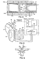
- Figure 4 is a schematic view illustrating a control system for the magnets which provide heat and maintain the desired temperature of the spinning rotor;
- Figure 5 is an enlarged sectional plan view taken on the line 5-5 of Figure 1 and illustrating the manner in which the flow of polymer to the rotor housing is controlled to provide a balanced flow;
- Figure 6 is a sectional fragmentary side elevational view through the rotor housing; and
- Figure 7 is a fragmentary plan view portraying a hinge mounting for the rotor housing cover.
- It is to be understood that the aforementioned U. S. patent, provides an excellent description of a machine of the type to which the present improvements are directed, and that description will not be repeated in detail. Attention is, first of all, directed to Figures 1 and 6 hereof. The invention is concerned with a housing generally designated 10, within which a cooled rotor shaft is mounted, and on which a hollow rotor 11 is mounted to be driven by a suitable electric motor or the like at speeds preferably on the order of about 2000 to 4000 r.p.m. The rotor 11, as in the patent mentioned, includes a plurality of radially directed polymer
strand expressing orifices 12, opening from the interior of the rotor through therotor rim 13. - As Figure 6 particularly indicates, at the side of the rotor 11, opposite its coupling to shaft S, a
hollow sleeve 14 extends axially outwardly from the rotor side wall beyond theadjacent side wall 15 ofhousing 10,sleeve 14 passing freely through an opening 16 in the rotorhousing side wall 15, which is mounted to be separable from the remainder of the housing so that it can function as a cover plate.Rotor sleeve 14 is formed with acentral opening 14a, into which astationary feed tube 17 may be inserted with clearance to feed a hot and fluid thermoplastic material at a predetermined velocity or feed rate into the hollow interior of rotor 11 opposite animpeller 18 having a flared annular surface 18a, and afront face 18b broken by communicatingslots 18c extending radially at 90° intervals to form impellers which help to accelerate the flow from the zero r.p.m. at which the polymer is received, to the speed of rotation of rotor 11. - Provided within
tube 17 arefins 19, cruci- formly arranged in the embodiment shown which are of a length, at the outlet ofpipe 17, about one pipe diameter long. While the cruciform arrangement offins 19 is presently preferred, it is also thought that other useful divisions might be 3, 5, 6, or 8. - The dividing
fins 19 divide and divert the flow in the manner indicated in Figure 5 in a uniform angular manner to avoid the creation of imbalances which would tend to cause the rotor 11 to vibrate. Withoutfins 19, the approximately parabolic flow profile of polymer down thefeed tube 17, caused by the fact that the velocity is much higher at the center than at the wall, tends to prevent the divergence of undivided flows, and this also is a problem if thefins 19 are too long. - With rotation of rotor 11, thermoplastic material heated to a flowable state and thence fed from
tube 17 in divergent flow paths against theprotrusion 18, is directed and impelled radially, and then centrifugally expressed from the interior of rotor 11 throughorifices 12. The strands are, as previously, converted into pellets by a severing device generally designated 20 of the same type as in the aforementioned patent. The severingdevice 20 may include abracket 21, upon which a pair ofpulleys pulley 22 may be a driven pulley mounted upon theshaft 24 of a drive motor whose housing is fixedly mounted upon thebracket 21. Idlerpulley 23 is mounted for free rotation about ashaft 25, carried on anarm 26 mounted onbracket 21, and an endless severing band 27 (which may be constructed of thin spring steel in the range 0.1 to 1.0 mm. in thickness) is trained aboutpulleys endless band 27 extends generally parallelly to the axis of rotor 11 and is located to extend transversely across the path of movement of the strands of plastic expressed from therotor orifices 12. - Still referring to Figure 6, it is seen that
housing 10 includes rotorhousing side plates housing 10 is, however, spaced a substantial distance from the periphery of rotor 11 to allow for a substantial radial growth and projection of strands from therotor orifices 12 and provide a chamber C between wall 28a and the rotor 11. As previously, the rotor housing is formed with an opening 29 (Figure 1) to permit movement of theband 27 and band assembly into and out of operative relationship with the rotor 11. -
Member 30, which forms a continuation ofrotor housing 10, comprises a pellet-passing and quenching water spray duct for receiving pellets which are severed by theband 27 and conducting them viapassage 31, through a further cooling and coolant conducting system (not shown). Pellets severed by theband 27 continue in straight line motion, in a path that is generally tangential to rotor 11, and pass into thepassage 31 which hascoolant spray ports 32 provided therein. - It is necessary that the rotor 11 be heated to bring it up to the temperature desirable for extrusion and pelletizing of the particular thermoplastic material being processed, and this heating must be maintained to offset heat losses from the rotor to its surroundings to maintain the die cappilaries at a temperature high enough to prevent solidifcation of the polymer being processed, and to transfer heat to the polymer being fed, if it is not at a high enough temperature for processing. Chisholm U. S. patent 3,483,281, issued December 9, 1969, discloses an eddy current heating system for accomplishing this, and the system to be described herein incorporates certain patentable improvements which greatly enhance the practicality of such a system.
- - As Figures 1 and 2 disclose,
electromagnet assemblies 33, generally designated 33a and 33b, are provided at each side of the pelletizing machine, supported onrotor housing 10 in opposed alignment. Eachassembly 33 includes, in the embodiment shown, a complement of preferably fourelectromagnets 34, comprising, as usual,iron cores 34a surrounded byfield windings 34b. Eachmagnet assembly 33 further includes front and back magneticfield connecting plates - As Figure 3 indicates, the
magnet plate 36 extends sufficiently inwardly to overlie the peripheral end ofrotor housing 10, while theplate 35 is split as at 35', for a purpose which will later be described, and has an abutting extension portion 35a. - The plates or arms 35-35a and 36 are made up of very high magnetic permeability material, such as steel or iron. The
cover 37 androtor housing 10, however, are constructed of a relatively low permeability material, such as aluminum or 300 Series stainless steel. Provided inslots 38, cut in thehousing side walls flux plates 39 which have contact with the magnet plates 35-35a and 36, and which lie in close proximity, i.e., within less than 3mm., to the spinning rotor which itself is constructed of steel of high magnetic conductivity. In view of this proximity, we avoid the diminishing of the flux intensity across the air gaps and, because thehousing 10 is constructed of a low permeability material, magnetic lines of force do not short circuit across thehousing 10. Rather, they create eddy currents within the spinning rotor 11 which causes the rotor 11 to heat to the desired temperature when a direct current of a predetermined controlled amerage is applied to thewinding coils 34b, in each of theassemblies - Figures 2 and 3 are sections through the
magnet assembly 33a. It is to be understood that themagnet assembly 33b is identical, except that themagnet plates 35 and 35a are connected by ahinge 40, comprisingplates 40a connected by ahinge pin 40b. Withassemblies front wall 15 ofrotor housing 10 can be pivoted outwardly about thehinge pin 40b to provide ready access to the rotor when the pelletizing operation has finished and it is desired to have access to the interior of the rotor. - Normally commercially available toggle clamps, generally designated C, of a readily releasable variety, are provided for securing the
cover 15 securely in place. This ready accessibility facilitates maintenance, cleaning, and whatever is necessary in the way of changing parts, or replacement thereof. Because the magnet assemblies are housing supported in the manner indicated, they do not create interference with either the feed supply or spindle support systems. - The electromagnets in
assembly 33a provide a magnetic field of one polarity, while the electromagnets inassembly 33b provide an electromagnetic field of opposite polarity, since it is necessary from a practical point of view that the spinning rotor pass through magnetic fields of opposite polarity. This is accomplished by winding the coils in opposite directions at the 33a and 33b locations to create a different north-south pole arrangement at each location. Since the amount of heat generated within the spinning rotor 11 is dependent upon the number of lines of force being cut by the rotor and the flux is controlled by the current in themagnet coil windings 34b, a control of the rotor die temperature can be provided by sensing the temperature of the rotor via an infrared wave length radiation measuring optical pyrometer,and using the signal generated to control current flow to thecoils 34b. - In Figure 4 this commercially available, non-contact radiation sensor device is shown generally at 41, secured to the
rotor housing wall 28. Thelens system 41a of the device provides single lens reflex focusing along a line of sight at 41b which is shown also in Figure 3 as directed at the rim of rotor 11 between the rows oforifices 12. It is control of the temperatures of the walls of theorifices 12 along their length which is important to provide a properly flowing polymer which does not plug the orifices, and yet, is not overheated. The sensor head focuses on a small spot adjacent theorifices 12, i.e., in the neighborhood of 1/2 inch diameter, and is preferably sensitive to a narrow band of radiation which it integrates to an average temperature over a time period (see Figure 4). Thesensing head 40 may be a commercially available Capintech/Heimann model obtainable from Capintec Instruments, Inc., of Ramsey, New Jersey, U.S.A., or Ray-O-Tube® unit obtainable from Leeds and Northrup Company of North Wales, Pennsylvania, U.S.A., or a unit obtained from Ircon Company of Skokie, Illinois, U.S.A. The pyrometer electrically connects to a commerciallyavailable signal converter 42, such as a unit obtainable from Capintech, or the Leeds and Northrup linearizer, or an Ircon indicator unit, which converts its output signal to a linear scale temperature signal, having a DC millivolt output. - In the linearizer, the signal from the sensor is amplified, compensated for the emissivity factor, and converted to binary form. The binary signal is the input to a microprocessor that linearizes the measurement and performs the computation necessary for the averaging and peak picking. The results of this computation can be displayed in temperature units and in the present system are sent to output circuits.
- A current-adjusting
type temperature controller 43 such as the Leeds and Northrup Electromax V, or Ircon's proportional controller, is electrically connected with thesignal converter 42 to compare the actual (input) signal with a signal representing temperature which is preset oncontroller 43 and provide a "differential" output signal. Then this signal is in turn fed to aDC power controller 44, which modulates the current supply flowing to the electromagnets. The power controller, which provides the controlled current DC output to the field coils 34b from a suitable line power source may be the Model 64600 Phaser power controller manufactured commercially by Research, Inc. of Minneapolis, Minnesota, U.S.A. All of theunits - Briefly, the pyrometer generates an electronic output signal which is dependent on the heat radiation sensed. This non-linear signal output is then converted to a linear temperature signal by the
signal converter 42, which has a millivolt output. The millivolt output signal is then supplied to the temperature controller which, in turn, provides a milliamp direct current control signal, and it is this signal which outputs to thepower controller 44 to modulate the supply of current to the magnet coils. - It is to be understood that the drawings and descriptive matter are in all cases to be interpreted as merely illustrative of the principles of the invention, rather than as limiting the same in any way, since it is contemplated that various changes may be made in various elements to achieve like results without departing from the spirit of the invention or the scope of the appended claims.
Claims (22)
Priority Applications (1)
| Application Number | Priority Date | Filing Date | Title |
|---|---|---|---|
| AT83110430T ATE32440T1 (en) | 1982-12-13 | 1983-10-19 | DEVICE AND PROCESS FOR CENTRAL GRANULATION. |
Applications Claiming Priority (2)
| Application Number | Priority Date | Filing Date | Title |
|---|---|---|---|
| US06/448,976 US4457882A (en) | 1982-12-13 | 1982-12-13 | Centrifugally powered pelletizing machine and method |
| US448976 | 1982-12-13 |
Publications (3)
| Publication Number | Publication Date |
|---|---|
| EP0111676A2 true EP0111676A2 (en) | 1984-06-27 |
| EP0111676A3 EP0111676A3 (en) | 1985-01-23 |
| EP0111676B1 EP0111676B1 (en) | 1988-02-10 |
Family
ID=23782394
Family Applications (1)
| Application Number | Title | Priority Date | Filing Date |
|---|---|---|---|
| EP83110430A Expired EP0111676B1 (en) | 1982-12-13 | 1983-10-19 | Centrifugally powered pelletizing machine and method |
Country Status (6)
| Country | Link |
|---|---|
| US (1) | US4457882A (en) |
| EP (1) | EP0111676B1 (en) |
| JP (1) | JPS59118417A (en) |
| AT (1) | ATE32440T1 (en) |
| CA (1) | CA1208406A (en) |
| DE (1) | DE3375648D1 (en) |
Cited By (1)
| Publication number | Priority date | Publication date | Assignee | Title |
|---|---|---|---|---|
| US7031693B2 (en) | 2001-09-13 | 2006-04-18 | Seamless Distribution Ab | Method and system for refilling mobile telephone prepaid phone cards via electronic distribution of refill codes |
Families Citing this family (1)
| Publication number | Priority date | Publication date | Assignee | Title |
|---|---|---|---|---|
| TWI549801B (en) * | 2009-06-18 | 2016-09-21 | 葛拉工業公司 | System for controlling cutter hub position in underfluid pelletizer |
Citations (4)
| Publication number | Priority date | Publication date | Assignee | Title |
|---|---|---|---|---|
| US3266085A (en) * | 1964-03-20 | 1966-08-16 | Dow Chemical Co | Apparatus to manufacture particulate thermoplastic resinous material |
| US3424832A (en) * | 1967-04-10 | 1969-01-28 | Dow Chemical Co | Processing of plastic |
| US3483281A (en) * | 1967-10-27 | 1969-12-09 | Dow Chemical Co | Centrifugal extrusion employing eddy currents |
| US4408972A (en) * | 1982-02-17 | 1983-10-11 | Baker Perkins Inc. | Centrifugal pelletizers |
Family Cites Families (1)
| Publication number | Priority date | Publication date | Assignee | Title |
|---|---|---|---|---|
| US3912799A (en) * | 1973-10-15 | 1975-10-14 | Dow Chemical Co | Centrifugal extrusion employing eddy currents |
-
1982
- 1982-12-13 US US06/448,976 patent/US4457882A/en not_active Expired - Lifetime
-
1983
- 1983-10-19 DE DE8383110430T patent/DE3375648D1/en not_active Expired
- 1983-10-19 EP EP83110430A patent/EP0111676B1/en not_active Expired
- 1983-10-19 AT AT83110430T patent/ATE32440T1/en not_active IP Right Cessation
- 1983-10-26 CA CA000439718A patent/CA1208406A/en not_active Expired
- 1983-12-12 JP JP58234125A patent/JPS59118417A/en active Pending
Patent Citations (4)
| Publication number | Priority date | Publication date | Assignee | Title |
|---|---|---|---|---|
| US3266085A (en) * | 1964-03-20 | 1966-08-16 | Dow Chemical Co | Apparatus to manufacture particulate thermoplastic resinous material |
| US3424832A (en) * | 1967-04-10 | 1969-01-28 | Dow Chemical Co | Processing of plastic |
| US3483281A (en) * | 1967-10-27 | 1969-12-09 | Dow Chemical Co | Centrifugal extrusion employing eddy currents |
| US4408972A (en) * | 1982-02-17 | 1983-10-11 | Baker Perkins Inc. | Centrifugal pelletizers |
Cited By (1)
| Publication number | Priority date | Publication date | Assignee | Title |
|---|---|---|---|---|
| US7031693B2 (en) | 2001-09-13 | 2006-04-18 | Seamless Distribution Ab | Method and system for refilling mobile telephone prepaid phone cards via electronic distribution of refill codes |
Also Published As
| Publication number | Publication date |
|---|---|
| EP0111676A3 (en) | 1985-01-23 |
| CA1208406A (en) | 1986-07-29 |
| DE3375648D1 (en) | 1988-03-17 |
| JPS59118417A (en) | 1984-07-09 |
| ATE32440T1 (en) | 1988-02-15 |
| US4457882A (en) | 1984-07-03 |
| EP0111676B1 (en) | 1988-02-10 |
Similar Documents
| Publication | Publication Date | Title |
|---|---|---|
| US4300877A (en) | Underwater pelletizer | |
| US5460498A (en) | Centrifugal spinning | |
| US4457882A (en) | Centrifugally powered pelletizing machine and method | |
| JPS5817389B2 (en) | Koondoniokeru | |
| US3483281A (en) | Centrifugal extrusion employing eddy currents | |
| JPH09268420A (en) | Melt spinning unit | |
| JP2017094172A (en) | Method for producing pharmaceutical product from dissolved material | |
| CA1179814A (en) | Centrifugal pelletizers and methods of centrifugally pelletizing | |
| MXPA04000946A (en) | Device for granulating a thermoplastic, which is extruded from nozzles. | |
| US4120625A (en) | Die face cutter | |
| EP3621455B1 (en) | Apparatus and method to treat dairy products | |
| JPH0810864A (en) | Electromagnetic forming device | |
| MXPA04000872A (en) | Device for granulating a thermoplastic, which is extruded from nozzles. | |
| US4412964A (en) | Centrifugal pelletizing systems and process | |
| JP6360419B2 (en) | 2-roll kneader | |
| CN108486666B (en) | Centrifugal spinning flocculation forming equipment | |
| CA1177216A (en) | Methods of centrifugally pelletizing certain synthetic plastic materials | |
| JP2002326269A (en) | Method and system for producing film from thermoplastic synthetic resin | |
| EP0087014B1 (en) | Improvements in centrifugal pelletizers and methods of centrifugally pelletizing | |
| CN108930035A (en) | The quick coating apparatus of inner wall | |
| JP2001241858A (en) | Guide tube structure for electromagnetic flux concentration | |
| SU1177168A1 (en) | Extruder for processing polymeric materials | |
| JP2005148260A (en) | Experimental apparatus for plastic product fiberization for teaching purpose | |
| JP4526950B2 (en) | Pipe casting machine with mold tunnel air turbulence | |
| CN110936611B (en) | 3D printer based on microwave even heating |
Legal Events
| Date | Code | Title | Description |
|---|---|---|---|
| PUAI | Public reference made under article 153(3) epc to a published international application that has entered the european phase |
Free format text: ORIGINAL CODE: 0009012 |
|
| AK | Designated contracting states |
Designated state(s): AT CH DE FR GB IT LI |
|
| PUAL | Search report despatched |
Free format text: ORIGINAL CODE: 0009013 |
|
| AK | Designated contracting states |
Designated state(s): AT CH DE FR GB IT LI |
|
| 17P | Request for examination filed |
Effective date: 19850712 |
|
| 17Q | First examination report despatched |
Effective date: 19860704 |
|
| GRAA | (expected) grant |
Free format text: ORIGINAL CODE: 0009210 |
|
| AK | Designated contracting states |
Kind code of ref document: B1 Designated state(s): AT CH DE FR GB IT LI |
|
| REF | Corresponds to: |
Ref document number: 32440 Country of ref document: AT Date of ref document: 19880215 Kind code of ref document: T |
|
| REF | Corresponds to: |
Ref document number: 3375648 Country of ref document: DE Date of ref document: 19880317 |
|
| ITF | It: translation for a ep patent filed |
Owner name: BARZANO' E ZANARDO MILANO S.P.A. |
|
| ET | Fr: translation filed | ||
| PLBE | No opposition filed within time limit |
Free format text: ORIGINAL CODE: 0009261 |
|
| STAA | Information on the status of an ep patent application or granted ep patent |
Free format text: STATUS: NO OPPOSITION FILED WITHIN TIME LIMIT |
|
| 26N | No opposition filed | ||
| PG25 | Lapsed in a contracting state [announced via postgrant information from national office to epo] |
Ref country code: GB Effective date: 19891019 Ref country code: AT Effective date: 19891019 |
|
| PG25 | Lapsed in a contracting state [announced via postgrant information from national office to epo] |
Ref country code: LI Effective date: 19891031 Ref country code: CH Effective date: 19891031 |
|
| GBPC | Gb: european patent ceased through non-payment of renewal fee | ||
| PG25 | Lapsed in a contracting state [announced via postgrant information from national office to epo] |
Ref country code: FR Effective date: 19900629 |
|
| REG | Reference to a national code |
Ref country code: CH Ref legal event code: PL |
|
| PG25 | Lapsed in a contracting state [announced via postgrant information from national office to epo] |
Ref country code: DE Effective date: 19900703 |
|
| REG | Reference to a national code |
Ref country code: FR Ref legal event code: ST |