EP0110708A2 - Method for compression moulding or embossing - Google Patents
Method for compression moulding or embossing Download PDFInfo
- Publication number
- EP0110708A2 EP0110708A2 EP83307267A EP83307267A EP0110708A2 EP 0110708 A2 EP0110708 A2 EP 0110708A2 EP 83307267 A EP83307267 A EP 83307267A EP 83307267 A EP83307267 A EP 83307267A EP 0110708 A2 EP0110708 A2 EP 0110708A2
- Authority
- EP
- European Patent Office
- Prior art keywords
- die
- article
- carrier plate
- pressed
- adhesive
- Prior art date
- Legal status (The legal status is an assumption and is not a legal conclusion. Google has not performed a legal analysis and makes no representation as to the accuracy of the status listed.)
- Granted
Links
Images


Classifications
-
- B—PERFORMING OPERATIONS; TRANSPORTING
- B44—DECORATIVE ARTS
- B44B—MACHINES, APPARATUS OR TOOLS FOR ARTISTIC WORK, e.g. FOR SCULPTURING, GUILLOCHING, CARVING, BRANDING, INLAYING
- B44B5/00—Machines or apparatus for embossing decorations or marks, e.g. embossing coins
-
- B—PERFORMING OPERATIONS; TRANSPORTING
- B27—WORKING OR PRESERVING WOOD OR SIMILAR MATERIAL; NAILING OR STAPLING MACHINES IN GENERAL
- B27M—WORKING OF WOOD NOT PROVIDED FOR IN SUBCLASSES B27B - B27L; MANUFACTURE OF SPECIFIC WOODEN ARTICLES
- B27M1/00—Working of wood not provided for in subclasses B27B - B27L, e.g. by stretching
- B27M1/02—Working of wood not provided for in subclasses B27B - B27L, e.g. by stretching by compressing
-
- B—PERFORMING OPERATIONS; TRANSPORTING
- B29—WORKING OF PLASTICS; WORKING OF SUBSTANCES IN A PLASTIC STATE IN GENERAL
- B29C—SHAPING OR JOINING OF PLASTICS; SHAPING OF MATERIAL IN A PLASTIC STATE, NOT OTHERWISE PROVIDED FOR; AFTER-TREATMENT OF THE SHAPED PRODUCTS, e.g. REPAIRING
- B29C59/00—Surface shaping of articles, e.g. embossing; Apparatus therefor
- B29C59/02—Surface shaping of articles, e.g. embossing; Apparatus therefor by mechanical means, e.g. pressing
-
- B—PERFORMING OPERATIONS; TRANSPORTING
- B44—DECORATIVE ARTS
- B44B—MACHINES, APPARATUS OR TOOLS FOR ARTISTIC WORK, e.g. FOR SCULPTURING, GUILLOCHING, CARVING, BRANDING, INLAYING
- B44B5/00—Machines or apparatus for embossing decorations or marks, e.g. embossing coins
- B44B5/0047—Machines or apparatus for embossing decorations or marks, e.g. embossing coins by rolling
-
- B—PERFORMING OPERATIONS; TRANSPORTING
- B44—DECORATIVE ARTS
- B44B—MACHINES, APPARATUS OR TOOLS FOR ARTISTIC WORK, e.g. FOR SCULPTURING, GUILLOCHING, CARVING, BRANDING, INLAYING
- B44B5/00—Machines or apparatus for embossing decorations or marks, e.g. embossing coins
- B44B5/02—Dies; Accessories
- B44B5/026—Dies
Definitions
- This invention relates to a method and an apparatus which uses a die for compression moulding and embossing the surface of a relatively soft article or substrate such as wood, thermoplastics material or various varieties of particle board such as chipboard, flake board, fibre board, sawdust board and the like.
- the invention was developed with special reference to compression moulding and decorative surface embossing of wood based furniture door panels, but its applications are by no means thus limited, as will become apparent from the following description.
- a standard compression moulding and embossing procedure is to impress the required pattern using a metal die at a high temperature and pressure.
- Conventional metal dies are commonly made by casting, machirtng or spark erosion, all expensive and difficult processes. They are, furthermore usually placed into direct contact with the surface of the means which supplies the pressure and heat to the die.
- the design of conventional dies and the method of anchorage to the surface of the pressure/heating means dictates that a minimum distance from the surface to the deepest point of die must obtain. This gives rise to heat transfer problems, with the leading or deepest part of the die from the heating surface tending to be cooler and the outer periphery of the
- the invention seeks, as a primary object, to provide at inexpensive method of making dies which can be used economically for experimental and short runs that can be discarded without seriois financial loss, and, as a subsidiary object, to overcome the heat transfer problem. It is a further object of the invention to produce dies which can give a sharp profile at any required place in the pattern, but in particular at the periphery thereof.
- the invention therefore provides an apparatus for use in compression moulding or embossing including at least one die adapted to be heated and pressed into the surface of an article to be moulded or embossed, characterised in that the die is secured to one surface of a carrier plate which is of thermally conductive material and extends laterally beyond the edges of the die, the opposite surface of the carrier plate being attachable to means for applying heat and pressure to the die via the plate.
- the use of a carrier plate enables heat to transfer uniformally from the pressure/heating means to the die.
- the apparatus may be used for surface decoration by a match mould process as hereinafter described.
- the die is of laminar construction and comprises a stack of at least two pieces of sheet material individually shaped such that together they define the desired overall shape of the die.
- Such a die may be manufactured, to a maximum embossing depth D given by nd ? D where n is a whole number and d is the thickness of available stock sheet selected for die or mould making, by notionally slicing the desired final die body, parallel to or conformably with the base thereof, into strata each of thickness d, forming each stratum from said stock sheet in one piece or several discrete pieces as determined by the die pattern when so sliced, assembling the die body by sandwiching the formed strata together to constitute the required shape, and adapting the die body, or the lowermost stratum thereof, for attachment to the carrier plate.
- carrier plate can be used in connection with dies produced in the conventional manner instead of laminar dies as described above.
- each stratum is a part cylindrical shell of constant inner and outer radius concentric with the carrier plate.
- the carrier plate will be cylindrical or part cylindrical when it is intended to be applied to pressure rollers for continuous embossing, instead of to flat plates for repetitive embossing.
- the material of choice for the stock sheet used for making the dies is aluminium, but other metals, both soft and hard including brass, and even hard thermosetting plastics, may be used.
- a laminar die made as above is very similar in structure to a well known type of geographical relief model built up from superimposed slices of wood or plastics of suitable thickness, each successive slice being cut to represent a successive contour line on a corresponding flat map.
- the notional process of slicing the die body is analogous to dismantling the geographical relief model into its component contour layers.
- the profile of the die body in section, however, unlike that of the model, is not normally stepped but smooth.
- the carrier plate to which the die is affixed for use, is preferably made from a sheet of metal of high thermal conductivity, such as aluminium. In use the carrier plate is protected from distortion by close attachment in any suitable manner to a pressure plate or roller of stronger material such as steel.
- Attachment of the die strata one to another, and of the die to the carrier plate can be by means of screws of rivets or a suitable adhesive composition, with or without locating pins and corresponding holes to facilitate correct assembly with all the edges in register, and a smooth (or unstepped) cross-sectional profile.
- a plurality of dies may be affixed to single carrier plate.
- large areas of the article or substrate may be worked in a single pass or pressing, up to and including the standard sizes (e.g. 8 feet x 4 feet) in which wood based composition boards are commercially available.
- the uniformly headed surface of the carrier plate carrying the die or dies preferably contacts the surface of the article or sub strata being embossed. While due to its relatively large area the carrier plate does not compress the substrate to any appreciable extent, by its even temperature and pressure it reduces the fibre fatigue and enchances the malleability of the article or substrate around the upper or outer edges of embossed or moulded substrates. This gives unbroken edges and a sharp sectional profile to the design, overcoming the "cold leading edge" problem.
- the carrier plate is relatively cheap, dies or moulds may be permanently affixed or bonded thereto, and new sheet stock used for new carrier plates.
- the size of the carrier plate is limited only by the size of the pressure plate, or roller, in the pressing medium available to the operator.
- the dies may, of course, exhibit wear after much repeated use, but when manufactured in laminar form as described above, they are cheap enough to replace economically.
- the raw material for their manufacture, such as aluminium, is available in the form of sheets of precise uniform thickness at reasonable cost.
- a carrier plate 1 comprises a 6 feet x 2 feet sheet of 1/4" sheet aluminium. It bears adhesively or mechanically affixed thereto four dies 2, the assembly being intended for use in an embossing press having a pressure plate at least 6 feet x 2 feet and conventional heating facilities. Moulding or embossing is carried out in the press at a pressure of several hundred pounds per square inch at a temperature of between 10 and 260°C, the dwell time being anything from 30 seconds to 5 minutes. The pressure may range from 100 to 1000 pounds per square inch, except in the case of high density fibre board (wallboard) for which a pressure of several thousand pounds per square inch may be necessary. Alternatively, where the density of the substrate is very high as in the Medium Density Fibre board, a rough pre-machining of the design area will enable a lower pressure requirement to be utilised. Heating is by any suitable means such as steam or low voltage electricity.
- the die 2 is laminar and is made up from two cutouts 3 and 4 of 1/8 inch thick aluminium sheet, the side faces 5 of which are chamfered.
- the cutouts 3, 4 are fixed together in intimate contact using a commercial adhesive or by a mechanical method.
- Locating pins project from holes on the carrier plate 1, and the dies are located on the plate in intimate contact therewith by means of corresponding holes in the underside of the cutouts 3.
- the cutout 4, which is circular, has a central opening 8 of decorative shape with chamfered sides 5 which produces an upstanding decorative relief portion 9 of corresponding shape in the embossed article 12.
- the cutouts 3 and 4 conversely produce depressions 10, 11 in the finished article 12.
- roller 21 which rotate in the direction of the arrows shown thereon.
- the roller 21 is the equivalent of a pressure and heating chamber and affixed thereto is a carrier plate having a pair of dies 23, 24 of the type described above.
- a substrate 25 passes between the rollers 20, 21 and the dies produce the decorative reliefs and shapes as previously described.
- Fig. 7 (which is not part of the present invention and is present for comparative purposes only) shows a conventional pressure and heating chamber 30 having a die or tool 31 affixed thereto.
- a substrate 33 is shown and as will be observed, when the die 31 presses on the substrate 33, only a portion of the substrate 33 is exposed to the action of the die 31 and consequently a cold leading edge effect is usually observed at X and X as shown in Fig. 7.
- a fixing screw 34 is provided which fastens the die 31 to the chamber 30.
- a further problem with conventional dies similar to Fig. 7 is that critical adjustement of the downward stroke is required, but almost impossible to attain, while avoiding damage to the surface of the substrate at 'X' in Fig. 7 particularly when there is a surface decoration film having a thickness as low as 0.125mm present.
- a pressure and heating chamber 40 having a carrier plate 41 and die 42 according to the present invention thereon, the carrier plate 41 having the die 42 affixed thereto as previously described. It will be observed that in Fig. 7, only the die per se contacts the substrate, whereas in Fig. 8, both the die 42 and the surrounding portion of the carrier plate 41 contacts the substrate. The effect of this is that the surface of the carrier plate functions effectively as a die and presses on the substrates very slightly. The result is the virtual elimination of the cold leading edge effect which in turn provides clarity of design and elimination of damage to the substrate 43.
- the substrate 43 has already been embossed as it is necessary to apply a surface decorative finish 44 to the substrate.
- the substrate 43 may be raw chipboard and the surface decorative finish 44 may be a wood veneer.
- Adhesive is applied to the embossed surface of the substrate 43 and the pressure/heating chamber 40, the carrier plate 41 and the mould 42 are lowered onto the substrate 43 which lowering forms the surface decorative finish 44 and presses it onto the substrate 43.
- the heat and pressure enable the surface decorative finish 44 to adhere to the substrate 43.
- the surface decorative finish is porous and allows the heated adhesive to pass through it onto its upper surface thereby ruining the finish.
- an adhesive film 45 rather than a liquid adhesive which film consists of paper impregnated with adhesive.
- An example of such an adhesive film is Tego Glue Film.
- the film 45 is placed on the substrate and the surface decorative finish 44 placed on top of the film 45.
- the paper of the film 45 forms a membrane which prevents excess adhesive from passing through the pores of the decorative surface finish 44.
- the use of the film 45 provides a controlled quantity of adhesive which, over a period of time, reduces the overall costs of making such a laminate finish.
Abstract
Description
- This invention relates to a method and an apparatus which uses a die for compression moulding and embossing the surface of a relatively soft article or substrate such as wood, thermoplastics material or various varieties of particle board such as chipboard, flake board, fibre board, sawdust board and the like. The invention was developed with special reference to compression moulding and decorative surface embossing of wood based furniture door panels, but its applications are by no means thus limited, as will become apparent from the following description.
- It is now often desired to achieve the effect of machined or carved decoration, or of panel construction, in cheaper materials than solid wood, plywood, etc., in which such effects have.previously been created. This is the case in all types of furniture manufacture, wall and ceiling panelling, partitioning, coffins and other structures. The cheaper materials are those mentioned above, and composite materials made from them.
- A standard compression moulding and embossing procedure is to impress the required pattern using a metal die at a high temperature and pressure. Conventional metal dies are commonly made by casting, machirtng or spark erosion, all expensive and difficult processes. They are, furthermore usually placed into direct contact with the surface of the means which supplies the pressure and heat to the die. The design of conventional dies and the method of anchorage to the surface of the pressure/heating means dictates that a minimum distance from the surface to the deepest point of die must obtain. This gives rise to heat transfer problems, with the leading or deepest part of the die from the heating surface tending to be cooler and the outer periphery of the
- die is also cooler. This problem, and the fact that conventional dies usually only transfer heat to the article or substrate in the immediate design area, often damages ths outer periphery of the design area during the processing, and obscurity of the design is obtained. This occurrence is primarily due to inadequate heating and pressure in the periphery area. This is commonly referred to as the "cold leading edge".
- The invention seeks, as a primary object, to provide at inexpensive method of making dies which can be used economically for experimental and short runs that can be discarded without seriois financial loss, and, as a subsidiary object, to overcome the heat transfer problem. It is a further object of the invention to produce dies which can give a sharp profile at any required place in the pattern, but in particular at the periphery thereof.
- The invention therefore provides an apparatus for use in compression moulding or embossing including at least one die adapted to be heated and pressed into the surface of an article to be moulded or embossed, characterised in that the die is secured to one surface of a carrier plate which is of thermally conductive material and extends laterally beyond the edges of the die, the opposite surface of the carrier plate being attachable to means for applying heat and pressure to the die via the plate.
- The use of a carrier plate enables heat to transfer uniformally from the pressure/heating means to the die.
- Naturally, the apparatus may be used for surface decoration by a match mould process as hereinafter described.
- The use of the carrier plate has further distinct advantages namely:-
- 1. Where the penetration depth of the compression moulding or embossing of a surfaced or pre-surfaced article or substrate does not exceed 2mm.
- 2. In the use of the die and carrier plate in conjunction with a previously moulded substrate by the same tool to form a match mould process. This allows a highly defined moulded substrate to be accurately surface decorated and, if required, permanently bonded with such material as wood veneer, synthetic veneer, plastic foils etc., giving the effect of having being carved or machined from solid wood with a penetration depth in excess of 2mm.
- 3. In the use of a die and carrier plate for embossing and moulding and surface decorating of either flat or premoulded substrates with uncured resin films such as melamine where the uniform temperature and pressure obtained allows the fusing and self bonding of the films in one operation.
- Preferably the die is of laminar construction and comprises a stack of at least two pieces of sheet material individually shaped such that together they define the desired overall shape of the die.
- Such a die may be manufactured, to a maximum embossing depth D given by nd ? D where n is a whole number and d is the thickness of available stock sheet selected for die or mould making, by notionally slicing the desired final die body, parallel to or conformably with the base thereof, into strata each of thickness d, forming each stratum from said stock sheet in one piece or several discrete pieces as determined by the die pattern when so sliced, assembling the die body by sandwiching the formed strata together to constitute the required shape, and adapting the die body, or the lowermost stratum thereof, for attachment to the carrier plate.
- It is to be understood, however, that the carrier plate can be used in connection with dies produced in the conventional manner instead of laminar dies as described above.
- When the carrier plate is cylindrical or part cylindrical, each stratum is a part cylindrical shell of constant inner and outer radius concentric with the carrier plate. The carrier plate will be cylindrical or part cylindrical when it is intended to be applied to pressure rollers for continuous embossing, instead of to flat plates for repetitive embossing. The material of choice for the stock sheet used for making the dies is aluminium, but other metals, both soft and hard including brass, and even hard thermosetting plastics, may be used.
- A laminar die made as above is very similar in structure to a well known type of geographical relief model built up from superimposed slices of wood or plastics of suitable thickness, each successive slice being cut to represent a successive contour line on a corresponding flat map. The notional process of slicing the die body is analogous to dismantling the geographical relief model into its component contour layers. The profile of the die body in section, however, unlike that of the model, is not normally stepped but smooth.
- The carrier plate, to which the die is affixed for use, is preferably made from a sheet of metal of high thermal conductivity, such as aluminium. In use the carrier plate is protected from distortion by close attachment in any suitable manner to a pressure plate or roller of stronger material such as steel.
- Attachment of the die strata one to another, and of the die to the carrier plate, can be by means of screws of rivets or a suitable adhesive composition, with or without locating pins and corresponding holes to facilitate correct assembly with all the edges in register, and a smooth (or unstepped) cross-sectional profile.
- While laminar dies are preferred for complex patterns, the die could be one in which n = 1, the pattern having a uniform depth equal to that of a single sheet of the stock die material, and the die therefore comprising but a single stratum.
- A plurality of dies may be affixed to single carrier plate. Thus large areas of the article or substrate may be worked in a single pass or pressing, up to and including the standard sizes (e.g. 8 feet x 4 feet) in which wood based composition boards are commercially available. The uniformly headed surface of the carrier plate carrying the die or dies preferably contacts the surface of the article or sub strata being embossed. While due to its relatively large area the carrier plate does not compress the substrate to any appreciable extent, by its even temperature and pressure it reduces the fibre fatigue and enchances the malleability of the article or substrate around the upper or outer edges of embossed or moulded substrates. This gives unbroken edges and a sharp sectional profile to the design, overcoming the "cold leading edge" problem.
- Since the carrier plate is relatively cheap, dies or moulds may be permanently affixed or bonded thereto, and new sheet stock used for new carrier plates. The size of the carrier plate is limited only by the size of the pressure plate, or roller, in the pressing medium available to the operator.
- It will be appreciated that the the dies may, of course, exhibit wear after much repeated use, but when manufactured in laminar form as described above, they are cheap enough to replace economically. The raw material for their manufacture, such as aluminium, is available in the form of sheets of precise uniform thickness at reasonable cost.
- The invention will be appreciated in greater detail from the following description of a particular and preferred embodiment thereof given by way of example only, with reference to the accompanying drawings, in which:-
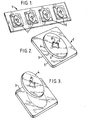
- Fig. 1 is a perspective view of a carrier plate with with four dies attached; four dies attached;
- Fig. 2 is a perspective view of one of the dies from Fig. 1;
- Fig. 3 is an exploded perspective view of the die of Fig. 2;
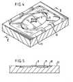
- Fig. 4 is a perspective view of a piece of substrate bearing a pattern embossed therein by means of the die of Fig. 2;
- Fig. 5 is a cross-section taken along the line V-V in Fig. 4, and viewed in the direction of the associated arrows to show the embossed profile;
- Fig. 6 shows a pair of rollers which act as pressure plates one of the rollers having a carrier plate;
- Fig. 7 is a cross-sectional view of a conventional die in use with a substrate (this Figure does not form part of the invention and is present for comparative purposes only);
- Fig. 8 is a cross-sectional view of a die and carrier plate according to the invention in use with the substrate.
- Fig. 9 is Fig. 8 with the die and carrier plate removed and a surface decorative finish in position for attachment to the substrate; and
- Fig. 10 shows the surface decorative finish interposed between the substrate and the die and carrier plate.
- Referring now to the drawings, a carrier plate 1 comprises a 6 feet x 2 feet sheet of 1/4" sheet aluminium. It bears adhesively or mechanically affixed thereto four dies 2, the assembly being intended for use in an embossing press having a pressure plate at least 6 feet x 2 feet and conventional heating facilities. Moulding or embossing is carried out in the press at a pressure of several hundred pounds per square inch at a temperature of between 10 and 260°C, the dwell time being anything from 30 seconds to 5 minutes. The pressure may range from 100 to 1000 pounds per square inch, except in the case of high density fibre board (wallboard) for which a pressure of several thousand pounds per square inch may be necessary. Alternatively, where the density of the substrate is very high as in the Medium Density Fibre board, a rough pre-machining of the design area will enable a lower pressure requirement to be utilised. Heating is by any suitable means such as steam or low voltage electricity.
- The die 2 is laminar and is made up from two cutouts 3 and 4 of 1/8 inch thick aluminium sheet, the side faces 5 of which are chamfered. The cutouts 3, 4 are fixed together in intimate contact using a commercial adhesive or by a mechanical method.
- Locating pins (not shown) project from holes on the carrier plate 1, and the dies are located on the plate in intimate contact therewith by means of corresponding holes in the underside of the cutouts 3. The cutout 4, which is circular, has a central opening 8 of decorative shape with chamfered sides 5 which produces an upstanding
decorative relief portion 9 of corresponding shape in the embossedarticle 12. The cutouts 3 and 4 conversely producedepressions finished article 12. - Referring now to Fig. 6 of the Drawings, there is shown a pair of
rollers roller 21 is the equivalent of a pressure and heating chamber and affixed thereto is a carrier plate having a pair of dies 23, 24 of the type described above. - A
substrate 25 passes between therollers - Thus a continuous embossing process can be accomplished.
- Referring now to Figs. 7 and 8 of the drawings, Fig. 7 (which is not part of the present invention and is present for comparative purposes only) shows a conventional pressure and
heating chamber 30 having a die ortool 31 affixed thereto. Asubstrate 33 is shown and as will be observed, when the die 31 presses on thesubstrate 33, only a portion of thesubstrate 33 is exposed to the action of thedie 31 and consequently a cold leading edge effect is usually observed at X and X as shown in Fig. 7. As is known, a fixingscrew 34 is provided which fastens the die 31 to thechamber 30. A further problem with conventional dies similar to Fig. 7 is that critical adjustement of the downward stroke is required, but almost impossible to attain, while avoiding damage to the surface of the substrate at 'X' in Fig. 7 particularly when there is a surface decoration film having a thickness as low as 0.125mm present. - In Fig. 8, there is shown a pressure and
heating chamber 40 having acarrier plate 41 and die 42 according to the present invention thereon, thecarrier plate 41 having the die 42 affixed thereto as previously described. It will be observed that in Fig. 7, only the die per se contacts the substrate, whereas in Fig. 8, both thedie 42 and the surrounding portion of thecarrier plate 41 contacts the substrate. The effect of this is that the surface of the carrier plate functions effectively as a die and presses on the substrates very slightly. The result is the virtual elimination of the cold leading edge effect which in turn provides clarity of design and elimination of damage to thesubstrate 43. - Referring now to Figs. 9 and 10 of the drawings, in Fig. 9 the
substrate 43 has already been embossed as it is necessary to apply a surfacedecorative finish 44 to the substrate. For example, thesubstrate 43 may be raw chipboard and the surfacedecorative finish 44 may be a wood veneer. Adhesive is applied to the embossed surface of thesubstrate 43 and the pressure/heating chamber 40, thecarrier plate 41 and themould 42 are lowered onto thesubstrate 43 which lowering forms the surfacedecorative finish 44 and presses it onto thesubstrate 43. The heat and pressure enable the surfacedecorative finish 44 to adhere to thesubstrate 43. Sometimes a problem arises in that the surface decorative finish is porous and allows the heated adhesive to pass through it onto its upper surface thereby ruining the finish. This problem may be overcome by using anadhesive film 45 rather than a liquid adhesive which film consists of paper impregnated with adhesive. An example of such an adhesive film is Tego Glue Film. Thefilm 45 is placed on the substrate and the surfacedecorative finish 44 placed on top of thefilm 45. The paper of thefilm 45 forms a membrane which prevents excess adhesive from passing through the pores of thedecorative surface finish 44. Furthermore, the use of thefilm 45 provides a controlled quantity of adhesive which, over a period of time, reduces the overall costs of making such a laminate finish.
Claims (13)
Priority Applications (1)
| Application Number | Priority Date | Filing Date | Title |
|---|---|---|---|
| AT83307267T ATE73054T1 (en) | 1982-11-30 | 1983-11-29 | METHOD OF PRESSING OR EMBOSSING. |
Applications Claiming Priority (2)
| Application Number | Priority Date | Filing Date | Title |
|---|---|---|---|
| IE284982 | 1982-11-30 | ||
| IE2849/82A IE54665B1 (en) | 1982-11-30 | 1982-11-30 | Method for compression moulding or embossing |
Publications (3)
| Publication Number | Publication Date |
|---|---|
| EP0110708A2 true EP0110708A2 (en) | 1984-06-13 |
| EP0110708A3 EP0110708A3 (en) | 1985-08-28 |
| EP0110708B1 EP0110708B1 (en) | 1992-03-04 |
Family
ID=11036761
Family Applications (1)
| Application Number | Title | Priority Date | Filing Date |
|---|---|---|---|
| EP83307267A Expired - Lifetime EP0110708B1 (en) | 1982-11-30 | 1983-11-29 | Method for compression moulding or embossing |
Country Status (8)
| Country | Link |
|---|---|
| EP (1) | EP0110708B1 (en) |
| AT (1) | ATE73054T1 (en) |
| AU (1) | AU558326B2 (en) |
| CA (1) | CA1224316A (en) |
| DE (1) | DE3382516D1 (en) |
| IE (1) | IE54665B1 (en) |
| NZ (1) | NZ206424A (en) |
| ZA (1) | ZA838889B (en) |
Cited By (3)
| Publication number | Priority date | Publication date | Assignee | Title |
|---|---|---|---|---|
| US20070160862A1 (en) * | 2002-11-12 | 2007-07-12 | Bei-Hong Liang | Method of manufacturing a decorative substrate and decorative substrate produced thereby |
| WO2009082025A1 (en) * | 2007-12-25 | 2009-07-02 | Olympus Corporation | Compressed wood product and method of manufacturing same |
| EP3154755A4 (en) * | 2014-06-10 | 2017-11-22 | Ilvolankoski OY | Method for producing a wood product by means of hot pressing and use of method |
Families Citing this family (2)
| Publication number | Priority date | Publication date | Assignee | Title |
|---|---|---|---|---|
| AU682858B2 (en) * | 1993-06-08 | 1997-10-23 | A J Bates Limited | Surface treatment of building elements |
| TW201350355A (en) * | 2012-06-01 | 2013-12-16 | Hou-Fei Hu | A character die, character embossing method for hand tool by using the same and its product |
Citations (8)
| Publication number | Priority date | Publication date | Assignee | Title |
|---|---|---|---|---|
| DE426619C (en) * | 1924-09-28 | 1926-03-13 | Carl Lindstroem Akt Ges | Device for holding matrices or male molds |
| US1582714A (en) * | 1924-01-11 | 1926-04-27 | Scranton Button Company | Die for molding plastic material |
| US2343191A (en) * | 1943-05-01 | 1944-02-29 | Kinlein John George | Embossing |
| US2488301A (en) * | 1944-04-17 | 1949-11-15 | Lundstrom Carl Brynolf | Furniture component with hardened exposed surfaces |
| DE826253C (en) * | 1950-09-05 | 1951-12-27 | Karl Theodor Lang | Embossing form formed from male and female dies, especially for stamping presses |
| FR1009127A (en) * | 1950-01-26 | 1952-05-26 | Improvements to the molding of plastic objects | |
| US2752632A (en) * | 1952-02-19 | 1956-07-03 | Hedwin Corp | Mold for thermoplastic materials |
| DE2228926A1 (en) * | 1972-06-14 | 1973-12-20 | Waibel Bueromoebel Kg | Plastic coated chipboard - with deep textured plastic surface using synthetic resin impregnated intermediate layer |
-
1982
- 1982-11-30 IE IE2849/82A patent/IE54665B1/en not_active IP Right Cessation
-
1983
- 1983-11-29 ZA ZA838889A patent/ZA838889B/en unknown
- 1983-11-29 CA CA000442133A patent/CA1224316A/en not_active Expired
- 1983-11-29 EP EP83307267A patent/EP0110708B1/en not_active Expired - Lifetime
- 1983-11-29 DE DE8383307267T patent/DE3382516D1/en not_active Expired - Lifetime
- 1983-11-29 AU AU21783/83A patent/AU558326B2/en not_active Ceased
- 1983-11-29 NZ NZ206424A patent/NZ206424A/en unknown
- 1983-11-29 AT AT83307267T patent/ATE73054T1/en not_active IP Right Cessation
Patent Citations (8)
| Publication number | Priority date | Publication date | Assignee | Title |
|---|---|---|---|---|
| US1582714A (en) * | 1924-01-11 | 1926-04-27 | Scranton Button Company | Die for molding plastic material |
| DE426619C (en) * | 1924-09-28 | 1926-03-13 | Carl Lindstroem Akt Ges | Device for holding matrices or male molds |
| US2343191A (en) * | 1943-05-01 | 1944-02-29 | Kinlein John George | Embossing |
| US2488301A (en) * | 1944-04-17 | 1949-11-15 | Lundstrom Carl Brynolf | Furniture component with hardened exposed surfaces |
| FR1009127A (en) * | 1950-01-26 | 1952-05-26 | Improvements to the molding of plastic objects | |
| DE826253C (en) * | 1950-09-05 | 1951-12-27 | Karl Theodor Lang | Embossing form formed from male and female dies, especially for stamping presses |
| US2752632A (en) * | 1952-02-19 | 1956-07-03 | Hedwin Corp | Mold for thermoplastic materials |
| DE2228926A1 (en) * | 1972-06-14 | 1973-12-20 | Waibel Bueromoebel Kg | Plastic coated chipboard - with deep textured plastic surface using synthetic resin impregnated intermediate layer |
Cited By (6)
| Publication number | Priority date | Publication date | Assignee | Title |
|---|---|---|---|---|
| US20070160862A1 (en) * | 2002-11-12 | 2007-07-12 | Bei-Hong Liang | Method of manufacturing a decorative substrate and decorative substrate produced thereby |
| US9352486B2 (en) * | 2002-11-12 | 2016-05-31 | Masonite Corporation | Decorative door skin composite article |
| US10562280B2 (en) | 2002-11-12 | 2020-02-18 | Masonite Corporation | Method of manufacturing a decorative substrate and decorative substrate produced thereby |
| WO2009082025A1 (en) * | 2007-12-25 | 2009-07-02 | Olympus Corporation | Compressed wood product and method of manufacturing same |
| EP3154755A4 (en) * | 2014-06-10 | 2017-11-22 | Ilvolankoski OY | Method for producing a wood product by means of hot pressing and use of method |
| US10434680B2 (en) | 2014-06-10 | 2019-10-08 | Ilvolankoski Oy | Method for producing a wood product by means of hot pressing and use of method |
Also Published As
| Publication number | Publication date |
|---|---|
| ATE73054T1 (en) | 1992-03-15 |
| DE3382516D1 (en) | 1992-04-09 |
| AU558326B2 (en) | 1987-01-29 |
| EP0110708B1 (en) | 1992-03-04 |
| EP0110708A3 (en) | 1985-08-28 |
| IE54665B1 (en) | 1990-01-03 |
| CA1224316A (en) | 1987-07-21 |
| AU2178383A (en) | 1984-06-07 |
| IE822849L (en) | 1984-05-30 |
| ZA838889B (en) | 1985-01-30 |
| NZ206424A (en) | 1986-03-14 |
Similar Documents
| Publication | Publication Date | Title |
|---|---|---|
| EP0246208B1 (en) | A heat form pressed product and a method of heat form pressing | |
| US3761338A (en) | Texturizing film for the manufacture of high pressure laminates | |
| US3698978A (en) | Registered embossed high pressure laminates | |
| US3802947A (en) | Embossed transfer for use in the formation of high pressure decorative laminates having registered color and emossing | |
| EP1567312B1 (en) | Method of manufacturing a decorative substrate | |
| US3732137A (en) | Preparation of high pressure decorative laminates having registered color and embossing using encapsulated ink | |
| US6210512B1 (en) | Embossing of laminated picture frame molding | |
| US3661672A (en) | Method of forming high pressure decorative laminates having registered color and embossing | |
| US20220024169A1 (en) | Press platen for creating deep structures | |
| EP0110708A2 (en) | Method for compression moulding or embossing | |
| US4828642A (en) | Process for the manufacture of parquet flooring blocks | |
| JPS6227990B2 (en) | ||
| KR20160123727A (en) | Embossed film surface board and manufacturing method thereof | |
| JPH018331Y2 (en) | ||
| JPS5835477Y2 (en) | Ototsumoyo Oyuusurukesyouban | |
| WO2007057752A1 (en) | Chipboard comprising decorative recess and manufacturing method | |
| JPH07266305A (en) | Architectural plate and manufacture thereof | |
| JPS591765Y2 (en) | "Tsuki" decorative board | |
| KR20070087774A (en) | Beauty panel for construction using metal sheet, and its making method | |
| CA1115631A (en) | Plastic embossing caul | |
| JPS6240190B2 (en) | ||
| DE59704285D1 (en) | DEVICE FOR INTAKING A SURFACE STRUCTURE IN A LAMINATE OR IN THE COATING OF A SUBSTRATE | |
| JPS5923249B2 (en) | Method for manufacturing embossed decorative sheet and decorative board | |
| JPS6327188B2 (en) | ||
| JPH0357856B2 (en) |
Legal Events
| Date | Code | Title | Description |
|---|---|---|---|
| PUAI | Public reference made under article 153(3) epc to a published international application that has entered the european phase |
Free format text: ORIGINAL CODE: 0009012 |
|
| AK | Designated contracting states |
Designated state(s): AT BE CH DE FR GB IT LI LU NL SE |
|
| PUAL | Search report despatched |
Free format text: ORIGINAL CODE: 0009013 |
|
| AK | Designated contracting states |
Designated state(s): AT BE CH DE FR GB IT LI LU NL SE |
|
| 17P | Request for examination filed |
Effective date: 19850927 |
|
| 17Q | First examination report despatched |
Effective date: 19860925 |
|
| D17Q | First examination report despatched (deleted) | ||
| GRAA | (expected) grant |
Free format text: ORIGINAL CODE: 0009210 |
|
| ITF | It: translation for a ep patent filed |
Owner name: BARZANO' E ZANARDO MILANO S.P.A. |
|
| AK | Designated contracting states |
Kind code of ref document: B1 Designated state(s): AT BE CH DE FR GB IT LI LU NL SE |
|
| PG25 | Lapsed in a contracting state [announced via postgrant information from national office to epo] |
Ref country code: AT Effective date: 19920304 |
|
| REF | Corresponds to: |
Ref document number: 73054 Country of ref document: AT Date of ref document: 19920315 Kind code of ref document: T |
|
| REF | Corresponds to: |
Ref document number: 3382516 Country of ref document: DE Date of ref document: 19920409 |
|
| ET | Fr: translation filed | ||
| PG25 | Lapsed in a contracting state [announced via postgrant information from national office to epo] |
Ref country code: LU Free format text: LAPSE BECAUSE OF NON-PAYMENT OF DUE FEES Effective date: 19921130 |
|
| PLBE | No opposition filed within time limit |
Free format text: ORIGINAL CODE: 0009261 |
|
| STAA | Information on the status of an ep patent application or granted ep patent |
Free format text: STATUS: NO OPPOSITION FILED WITHIN TIME LIMIT |
|
| 26N | No opposition filed | ||
| EAL | Se: european patent in force in sweden |
Ref document number: 83307267.1 |
|
| PGFP | Annual fee paid to national office [announced via postgrant information from national office to epo] |
Ref country code: CH Payment date: 19981111 Year of fee payment: 16 |
|
| PGFP | Annual fee paid to national office [announced via postgrant information from national office to epo] |
Ref country code: SE Payment date: 19981116 Year of fee payment: 16 |
|
| PGFP | Annual fee paid to national office [announced via postgrant information from national office to epo] |
Ref country code: NL Payment date: 19981130 Year of fee payment: 16 |
|
| PG25 | Lapsed in a contracting state [announced via postgrant information from national office to epo] |
Ref country code: SE Free format text: LAPSE BECAUSE OF NON-PAYMENT OF DUE FEES Effective date: 19991130 Ref country code: LI Free format text: LAPSE BECAUSE OF NON-PAYMENT OF DUE FEES Effective date: 19991130 Ref country code: CH Free format text: LAPSE BECAUSE OF NON-PAYMENT OF DUE FEES Effective date: 19991130 |
|
| PG25 | Lapsed in a contracting state [announced via postgrant information from national office to epo] |
Ref country code: NL Free format text: LAPSE BECAUSE OF NON-PAYMENT OF DUE FEES Effective date: 20000601 |
|
| REG | Reference to a national code |
Ref country code: CH Ref legal event code: PL |
|
| EUG | Se: european patent has lapsed |
Ref document number: 83307267.1 |
|
| NLV4 | Nl: lapsed or anulled due to non-payment of the annual fee |
Effective date: 20000601 |
|
| REG | Reference to a national code |
Ref country code: GB Ref legal event code: IF02 |
|
| PGFP | Annual fee paid to national office [announced via postgrant information from national office to epo] |
Ref country code: GB Payment date: 20021001 Year of fee payment: 20 |
|
| PGFP | Annual fee paid to national office [announced via postgrant information from national office to epo] |
Ref country code: FR Payment date: 20021017 Year of fee payment: 20 |
|
| PGFP | Annual fee paid to national office [announced via postgrant information from national office to epo] |
Ref country code: BE Payment date: 20021023 Year of fee payment: 20 |
|
| PGFP | Annual fee paid to national office [announced via postgrant information from national office to epo] |
Ref country code: DE Payment date: 20021126 Year of fee payment: 20 |
|
| PG25 | Lapsed in a contracting state [announced via postgrant information from national office to epo] |
Ref country code: GB Free format text: LAPSE BECAUSE OF EXPIRATION OF PROTECTION Effective date: 20031128 |
|
| BE20 | Be: patent expired |
Owner name: *GARTLAND MATTHEW Effective date: 20031129 |
|
| REG | Reference to a national code |
Ref country code: GB Ref legal event code: PE20 |
|
| APAH | Appeal reference modified |
Free format text: ORIGINAL CODE: EPIDOSCREFNO |