EP0110408A2 - Programmable controller - Google Patents
Programmable controller Download PDFInfo
- Publication number
- EP0110408A2 EP0110408A2 EP83112037A EP83112037A EP0110408A2 EP 0110408 A2 EP0110408 A2 EP 0110408A2 EP 83112037 A EP83112037 A EP 83112037A EP 83112037 A EP83112037 A EP 83112037A EP 0110408 A2 EP0110408 A2 EP 0110408A2
- Authority
- EP
- European Patent Office
- Prior art keywords
- bank
- data
- control
- controller
- link
- Prior art date
- Legal status (The legal status is an assumption and is not a legal conclusion. Google has not performed a legal analysis and makes no representation as to the accuracy of the status listed.)
- Granted
Links
Images

Classifications
-
- G—PHYSICS
- G05—CONTROLLING; REGULATING
- G05B—CONTROL OR REGULATING SYSTEMS IN GENERAL; FUNCTIONAL ELEMENTS OF SUCH SYSTEMS; MONITORING OR TESTING ARRANGEMENTS FOR SUCH SYSTEMS OR ELEMENTS
- G05B19/00—Programme-control systems
- G05B19/02—Programme-control systems electric
- G05B19/04—Programme control other than numerical control, i.e. in sequence controllers or logic controllers
- G05B19/10—Programme control other than numerical control, i.e. in sequence controllers or logic controllers using selector switches
- G05B19/102—Programme control other than numerical control, i.e. in sequence controllers or logic controllers using selector switches for input of programme steps, i.e. setting up sequence
-
- G—PHYSICS
- G05—CONTROLLING; REGULATING
- G05B—CONTROL OR REGULATING SYSTEMS IN GENERAL; FUNCTIONAL ELEMENTS OF SUCH SYSTEMS; MONITORING OR TESTING ARRANGEMENTS FOR SUCH SYSTEMS OR ELEMENTS
- G05B2219/00—Program-control systems
- G05B2219/20—Pc systems
- G05B2219/23—Pc programming
- G05B2219/23427—Selection out of several programs, parameters
-
- Y—GENERAL TAGGING OF NEW TECHNOLOGICAL DEVELOPMENTS; GENERAL TAGGING OF CROSS-SECTIONAL TECHNOLOGIES SPANNING OVER SEVERAL SECTIONS OF THE IPC; TECHNICAL SUBJECTS COVERED BY FORMER USPC CROSS-REFERENCE ART COLLECTIONS [XRACs] AND DIGESTS
- Y02—TECHNOLOGIES OR APPLICATIONS FOR MITIGATION OR ADAPTATION AGAINST CLIMATE CHANGE
- Y02P—CLIMATE CHANGE MITIGATION TECHNOLOGIES IN THE PRODUCTION OR PROCESSING OF GOODS
- Y02P90/00—Enabling technologies with a potential contribution to greenhouse gas [GHG] emissions mitigation
- Y02P90/02—Total factory control, e.g. smart factories, flexible manufacturing systems [FMS] or integrated manufacturing systems [IMS]
Definitions
- This invention relates to a programable controller, and more particularly to an improved programable controller for controlling on a time basis an object to be controlled in accordance with a predetermined program.
- a programable temperature controller provided with a microcomputor has in addition to a conventional temperature controlling function such a programable function that temperature of an object to be controlled is controlled on a time basis in accordance with a previously programmed temperature control pattern. Since the programable controller, however, can store only one kind of control cycle, a plurality of different control cycles cannot be set in the controller, so that whenever a different control cycle is necessary to be executed after execution of a control cycle, a new series of control steps in accordance with the different control cycle must be newly set in the controller with troublesome operation.
- a programable controller comprising storage means including a plurality of bank storage areas each storing bank data having a series of control steps and a link storage area storing link data designating a combination of the bank storage areas, input means for entering the bank data and the link data into the storage means, sensing means for sensing measured data from an object to be controlled by the controller, output means for powering the object, and control means for controlling the output means based on the sensed measured data generated from the sensing means so that the object may be controlled in accordance with the bank data and the link data.
- the programable controller of this invention may store a plurality of control patterns associated with the link data, so that it is not necessary to set control data prior to each execution of different control patterns.
- any combinations among the stored control patterns are available for control, a higher level or complicated control pattern can be constructed.
- the controller may be easily and flexibly used.
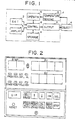
- a programable temperature controller 1 as a preferred embodiment of this invention though this invention is not limited to such a temperature controller but is applicable to other programable controllers.
- a temperature controller is employed in this embodiment.
- the programable temperature controller 1 includes a setting member 2 for setting control steps and control parameters such as P.I.D. (proportional, integral and differential) constants or the like, a display member 3 for displaying parameters or information on setting, a temperature sensing member 5 associated with an object member 4 to be controlled by the controller 1 so as to sense temperature of the object 4, an operation member 6 for operating a difference between a set temperature and a detection temperature, an output 7 including a heater, a motor and so on, a control member 8, and a storage 9.
- the control member 8 includes a central operation device and a read-only-memory so that in accordance with predetermined processes the temperature of the object 4 may be controlled through the output 7 based on an input obtained from the sensing member 5.
- Fig. 2 there is shown a front panel of the programable temperature controller 1.
- the setting member 2 and the display member 3 are mounted on lower and upper sections of the front panel, respectively.
- a DIP (dual-in-line- package) switch labelled as "DIP” for setting various modes of program protection or non-protection and so on
- a program-run switch labelled as "PRGM/RUN” for selecting a program mode to write or a run mode to execute a control program
- step switch labelled as "STEP” for selecting a parameter and further on the program mode for allowing a program writing
- numerical value control switches labelled " ⁇ ", "+” and “ ⁇ ” for respectively increasing, decreasing and shift-downing of a parameter value
- a repeat-hold switch labelled as "REPEAT/HOLD” for on the program mode designating times of repeating and for on the run mode holding a program execution
- a non- control-advance switch labelled to "NC/ADV” for on the program mode designating non-
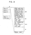
- the storage 9 consists of a random-access-memory (RAM) having storage areas for storing various control data entered through the setting member 2, a memory map of which is illustrated in Fig. 3.
- the storage 9 as illustrated in Fig. 3 consists of a bank area having a plurality of banks 00 to N for storing control data and a link area for storing link data.
- Each bank includes a series of control patterns consisting of a plurality steps, and controller of this embodiment performs a temperature control for each bank unit.
- the link data represent combinations of the banks.
- Each bank includes a storage area in a step S00 for storing control information commonly used in the bank, viz.
- the stage time defines a time period of a pulse signal generated at a turning point of each step.
- the continuous mode is a mode on which at a turning point of each step a predetermined output signal is automatically generated.
- Fig. 4 is a flow chart illustrating the operations for setting each control data in the temperature controller 1 and processed in the control member 8.
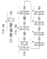
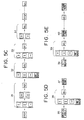
- Fig. 5A through 5E illustrate manual operations by the switches of Fig. 2 for the flow chart.
- the DIP switch DTP is actuated for setting non-protection mode
- the switch PRGM/RUN is set to program mode.
- a bank number is designated in such a manner that the switch SET/MEAS is set to a set value mode
- the switch BANK/LINK is set to a bank designation
- the switches "+" and "+” are pushed for designating a desired bank number
- the bank number is registered by the actuation of switch SEL.
- a step number is designated.
- the switch STEP the numerical control switches " ⁇ ", “ ⁇ ” and “+” and the switch SEL are actuated, so that a step number is entered.
- Each bank must be recorded with control information belonging to the bank in its initial stage. For this purpose, if a step number "00" is entered, a sequence from the step 21 flows through an inquiry step 22 to a step 23 where control parameters for the bank are entered. As illustrated in Fig.
- a sequence from the step 23 of Fig. 4 flows to a step 21 through an inquiry step 30, so that the designation of step number may be repeated.
- a side number S01 is entered, the sequence from the step 21 flows through the step 22 to a step 31 in which temperature, time and so forth are set. That is, as illustrated in a step 32 of Fig. 5C, a desired set temperature is designated by the numerical control switches "+", “+” and “+” or non-control is designated by the switch NC/ADV, and the temperature is registered by actuating the switch SEL. Then, in a step 33 a control time is designated and registered by the numerical control switches and the SEL switch.
- a stage time is registered, so that the step S01 registration is completed.
- the operations from step 21 to step 34 are repeated.
- control data in the respective steps S00 through Sn are registered, and then it is selected whether or not a control pattern in the bank is repeated. If the repeat of the control pattern is necessary, the switch REPEAT/HOLD is actuated (step 35 of Fig. 4 and Fig. 5D),.and a number of repeat times is selected and registered by the numerical control switches and the SEL switch (step 36 of Fig. 4 and Fig. 5D).
- the switch BANK/LINK is actuated so as to advance a sequence from a step 37 (Fig. 4 and Fig. 5D) to the step 20 for repeating similar registration.
- a step 37 Fig. 4 and Fig. 5D
- Fig. 5E illustrates manual operations for the registration.
- the switch SET/MEAS is actuated so as to advance a sequence from the step 37 to a step 39 through step 38, whereby a bank number of the bank to be initially operated is set and registered by the numerical control switches.
- the switch BANK/LINK is actuated so as to return the sequence from step 40 to the step 38, whereby the sequence from step 38 to step 40 is repeated so as to register link data in the storage 9. Thus, whole registration in the storage 9 is completed.
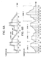
- Fig. 6A illustrates a temperature control pattern registered in a bank, e.g. bank 00, which consists of steps SO to S8 and in which the number of repeat times is set to two.
- a bank e.g. bank 00
- measuring operations are executed based on the pattern illustrated in Fig. 6A.
- the temperature of the object member 4 of Fig. 1 is controlled by the pattern and shown by a solid line curve of Fig. 6A regulated by upper and lower limit temperature curves. Since the repeat times are set to two, the same pattern is repeated twice. If link data is registered to repeat the same bank, further repeating the pattern of Fig. 6A may be performed.
- Fig. 6B illustrates another temperature control pattern registered in the storage 9 where the banks 00, 01 and 02 are linked in the order of BANK 0-1-0-2 by link data stored in the link data storage area.
- the bank 00, 01 and 02 respectively include of eight, five and twelve steps in addition to the respective first steps (S00).
- the link data stored in the storage 9 can easily provide freely combined bank patterns. If the controller 1 is designed to link k banks among the N banks, N k control patterns may be performed.
- temperature control patterns or programs may be designated by link operation prior to the execution of the run mode by the switch PROG/RUN.
- the switch SET/MEAS is set to the measuring mode
- set the switch BANK/LINK is set to the link mode so as to together with numerical control switches designate the operation order of banks to be executed.
- the numerical control switches of this embodiment include three types "+”, “ ⁇ ” and “ ⁇ ”, additional switch " ⁇ ” may be employed to shift up a parameter value or the like.
- the number of repeat times stored in the storage 9 may be stored in the control member 8, and further the link data stored in the storage 9 also may be stored in the control member 8, if desired.
- the programable controller according to this invention is adapted to store a plurality of control patterns and link data, so that the control patterns may be linked according to the stored link data for constituting larger number of control patterns than that of the stored patterns.
Abstract
Description
- This invention relates to a programable controller, and more particularly to an improved programable controller for controlling on a time basis an object to be controlled in accordance with a predetermined program.
- Recently developped microcomputor provides a controller with a programing function. For example, a programable temperature controller provided with a microcomputor has in addition to a conventional temperature controlling function such a programable function that temperature of an object to be controlled is controlled on a time basis in accordance with a previously programmed temperature control pattern. Since the programable controller, however, can store only one kind of control cycle, a plurality of different control cycles cannot be set in the controller, so that whenever a different control cycle is necessary to be executed after execution of a control cycle, a new series of control steps in accordance with the different control cycle must be newly set in the controller with troublesome operation.
- It is, therefore, a primary object of this invention to provide a programable controller adapted to store a plurality of control patterns combinable with one after another for a complicated control pattern.
- It is another object of this invention to provide a programable controller which is easy to preset any control programs with simple operations.
- In accordance with this invention, there is provided a programable controller comprising storage means including a plurality of bank storage areas each storing bank data having a series of control steps and a link storage area storing link data designating a combination of the bank storage areas, input means for entering the bank data and the link data into the storage means, sensing means for sensing measured data from an object to be controlled by the controller, output means for powering the object, and control means for controlling the output means based on the sensed measured data generated from the sensing means so that the object may be controlled in accordance with the bank data and the link data. Thus, the programable controller of this invention may store a plurality of control patterns associated with the link data, so that it is not necessary to set control data prior to each execution of different control patterns. Moreover, since any combinations among the stored control patterns are available for control, a higher level or complicated control pattern can be constructed. Thus, the controller may be easily and flexibly used.
- Other objects as well as the numerous advantages of the programable controller according to this invention will become apparent from the following detailed description and the accompanying drawings, in which:
-
- Fig. 1 is a schematic block diagram showing a programable controller as a preferred embodiment of this invention;
- Fig. 2 illustrates a front panel provided with a setting member and a display member which are employed in the controller of Fig. 1;
- Fig. 3 illustrates a storage map of a storage employed in the controller of Fig. 1;
- Fig. 4 is a flow chart illustrating a series of setting operations in the controller of Fig. 1;
- Figs. 5A through 5E show a series of manual operations for setting the controller of Fig. 1; and
- Figs. 6A and 6B illustrate different control patterns, respectively.
- Returning, now, to Fig. 1, there is shown a programable temperature controller 1 as a preferred embodiment of this invention though this invention is not limited to such a temperature controller but is applicable to other programable controllers. For the purpose of explanation, such a temperature controller is employed in this embodiment.
- The programable temperature controller 1 includes a
setting member 2 for setting control steps and control parameters such as P.I.D. (proportional, integral and differential) constants or the like, adisplay member 3 for displaying parameters or information on setting, atemperature sensing member 5 associated with anobject member 4 to be controlled by the controller 1 so as to sense temperature of theobject 4, anoperation member 6 for operating a difference between a set temperature and a detection temperature, anoutput 7 including a heater, a motor and so on, acontrol member 8, and a storage 9. Thecontrol member 8 includes a central operation device and a read-only-memory so that in accordance with predetermined processes the temperature of theobject 4 may be controlled through theoutput 7 based on an input obtained from thesensing member 5. - In Fig. 2 there is shown a front panel of the programable temperature controller 1. The
setting member 2 and thedisplay member 3 are mounted on lower and upper sections of the front panel, respectively. On the panel there are mounted a DIP (dual-in-line- package) switch labelled as "DIP" for setting various modes of program protection or non-protection and so on, a program-run switch labelled as "PRGM/RUN" for selecting a program mode to write or a run mode to execute a control program, a step switch labelled as "STEP" for selecting a parameter and further on the program mode for allowing a program writing, numerical value control switches labelled "†", "+" and "→" for respectively increasing, decreasing and shift-downing of a parameter value, a repeat-hold switch labelled as "REPEAT/HOLD" for on the program mode designating times of repeating and for on the run mode holding a program execution, a non- control-advance switch labelled to "NC/ADV" for on the program mode designating non-control or continuous repeat and for on the run mode advancing an execution forwards, a bank-link switch labelled as "BANK/LINK" for on the program mode designating a bank and for on the run mode designating a link, a set-measure switch labelled as "SET/MEAS" for selecting a display of a set value or a measured value, and a reset switch labelled as "RESET" for clearing parameters. - The storage 9 consists of a random-access-memory (RAM) having storage areas for storing various control data entered through the
setting member 2, a memory map of which is illustrated in Fig. 3. The storage 9 as illustrated in Fig. 3 consists of a bank area having a plurality ofbanks 00 to N for storing control data and a link area for storing link data. Each bank includes a series of control patterns consisting of a plurality steps, and controller of this embodiment performs a temperature control for each bank unit. The link data represent combinations of the banks. Each bank includes a storage area in a step S00 for storing control information commonly used in the bank, viz. upper alarm limit value, lower alarm limit value, proportion band, proportion cycle, integral time and differential time, a plurality of storage areas in steps S01 through Sn each for storing set temperature, set time, and stage time or continuous mode, and a storage area for storing a number of repeating times. The stage time defines a time period of a pulse signal generated at a turning point of each step. The continuous mode is a mode on which at a turning point of each step a predetermined output signal is automatically generated. - Fig. 4 is a flow chart illustrating the operations for setting each control data in the temperature controller 1 and processed in the
control member 8. Fig. 5A through 5E illustrate manual operations by the switches of Fig. 2 for the flow chart. As illustrated in Fig. 5A, the DIP switch DTP is actuated for setting non-protection mode, and the switch PRGM/RUN is set to program mode. In astep 20, a bank number is designated in such a manner that the switch SET/MEAS is set to a set value mode, the switch BANK/LINK is set to a bank designation, the switches "+" and "+" are pushed for designating a desired bank number, and the bank number is registered by the actuation of switch SEL. In a step 21 a step number is designated. As illustrated in Fig. 5B, the switch STEP, the numerical control switches "↑", "↓" and "+" and the switch SEL are actuated, so that a step number is entered. Each bank must be recorded with control information belonging to the bank in its initial stage. For this purpose, if a step number "00" is entered, a sequence from thestep 21 flows through aninquiry step 22 to astep 23 where control parameters for the bank are entered. As illustrated in Fig. 5B, when upper and lower limitation alarm is necessary, the numerical control switches "t", "↓" and "↠" are actuated to set desired limit values, or when such upper and lower limitation alarm is not necessary, the switch NC/ADV is actuated and thereafter the switch SEL is actuated so as to store data of alarm or no-alarm in the memory 9 (steps steps step 23 of Fig. 4 flows to astep 21 through aninquiry step 30, so that the designation of step number may be repeated. If a side number S01 is entered, the sequence from thestep 21 flows through thestep 22 to astep 31 in which temperature, time and so forth are set. That is, as illustrated in astep 32 of Fig. 5C, a desired set temperature is designated by the numerical control switches "+", "+" and "+" or non-control is designated by the switch NC/ADV, and the temperature is registered by actuating the switch SEL. Then, in a step 33 a control time is designated and registered by the numerical control switches and the SEL switch. In a subsequent step 34 a stage time is registered, so that the step S01 registration is completed. When the registrations of subsequent steps S02 ... Sn are necessary, the operations fromstep 21 tostep 34 are repeated. Thus, in the storage 9 control data in the respective steps S00 through Sn are registered, and then it is selected whether or not a control pattern in the bank is repeated. If the repeat of the control pattern is necessary, the switch REPEAT/HOLD is actuated (step 35 of Fig. 4 and Fig. 5D),.and a number of repeat times is selected and registered by the numerical control switches and the SEL switch (step 36 of Fig. 4 and Fig. 5D). If the repeat of the control pattern is unnecessary or the number of repeat times is finished to be registered and further control data are to be registered in another bank, the switch BANK/LINK is actuated so as to advance a sequence from a step 37 (Fig. 4 and Fig. 5D) to thestep 20 for repeating similar registration. Thus, the registration of data in bank storage areas is completed, and then an order of operations in the bank is registered in the storage 9 as link data. Fig. 5E illustrates manual operations for the registration. The switch SET/MEAS is actuated so as to advance a sequence from thestep 37 to astep 39 throughstep 38, whereby a bank number of the bank to be initially operated is set and registered by the numerical control switches. If any other bank is subsequently to be registered, the switch BANK/LINK is actuated so as to return the sequence fromstep 40 to thestep 38, whereby the sequence fromstep 38 to step 40 is repeated so as to register link data in the storage 9. Thus, whole registration in the storage 9 is completed. - Fig. 6A illustrates a temperature control pattern registered in a bank, e.g.
bank 00, which consists of steps SO to S8 and in which the number of repeat times is set to two. Upon actuation of the switch PROG/RUN to the run mode, measuring operations are executed based on the pattern illustrated in Fig. 6A. The temperature of theobject member 4 of Fig. 1 is controlled by the pattern and shown by a solid line curve of Fig. 6A regulated by upper and lower limit temperature curves. Since the repeat times are set to two, the same pattern is repeated twice. If link data is registered to repeat the same bank, further repeating the pattern of Fig. 6A may be performed. - Fig. 6B illustrates another temperature control pattern registered in the storage 9 where the
banks bank - In this embodiment, temperature control patterns or programs may be designated by link operation prior to the execution of the run mode by the switch PROG/RUN. For this purpose, firstly, the switch SET/MEAS is set to the measuring mode, and set the switch BANK/LINK is set to the link mode so as to together with numerical control switches designate the operation order of banks to be executed..Though the numerical control switches of this embodiment include three types "+", "↓" and "↠", additional switch "←" may be employed to shift up a parameter value or the like. Alternatively the number of repeat times stored in the storage 9 may be stored in the
control member 8, and further the link data stored in the storage 9 also may be stored in thecontrol member 8, if desired. - Thus, the programable controller according to this invention is adapted to store a plurality of control patterns and link data, so that the control patterns may be linked according to the stored link data for constituting larger number of control patterns than that of the stored patterns.
- It should be understood that the above description is merely illustrative of this invention and that many changes and modifications may be made by those skilled in the art without departing from the scope of the appended claims.
Claims (4)
Applications Claiming Priority (2)
| Application Number | Priority Date | Filing Date | Title |
|---|---|---|---|
| JP57211555A JPS59100905A (en) | 1982-12-01 | 1982-12-01 | Program control device |
| JP211555/82 | 1982-12-01 |
Publications (3)
| Publication Number | Publication Date |
|---|---|
| EP0110408A2 true EP0110408A2 (en) | 1984-06-13 |
| EP0110408A3 EP0110408A3 (en) | 1986-08-20 |
| EP0110408B1 EP0110408B1 (en) | 1990-02-28 |
Family
ID=16607744
Family Applications (1)
| Application Number | Title | Priority Date | Filing Date |
|---|---|---|---|
| EP83112037A Expired - Lifetime EP0110408B1 (en) | 1982-12-01 | 1983-11-30 | Programmable controller |
Country Status (4)
| Country | Link |
|---|---|
| US (1) | US4740884A (en) |
| EP (1) | EP0110408B1 (en) |
| JP (1) | JPS59100905A (en) |
| DE (1) | DE3381260D1 (en) |
Cited By (4)
| Publication number | Priority date | Publication date | Assignee | Title |
|---|---|---|---|---|
| EP0167848A1 (en) * | 1984-06-12 | 1986-01-15 | Elesta Ag Elektronik | Device and method for setting and displaying the switching times of a digital time switch |
| EP0236069A2 (en) * | 1986-02-25 | 1987-09-09 | The Perkin-Elmer Corporation | Apparatus and method for performing automated amplification of nucleic acid sequences and assays using heating and cooling steps |
| EP0631210A1 (en) * | 1993-06-21 | 1994-12-28 | Yamato Scientific Co., Ltd. | Method and apparatus for controlling temperature |
| US5656493A (en) * | 1985-03-28 | 1997-08-12 | The Perkin-Elmer Corporation | System for automated performance of the polymerase chain reaction |
Families Citing this family (10)
| Publication number | Priority date | Publication date | Assignee | Title |
|---|---|---|---|---|
| JPS6113302A (en) * | 1984-06-29 | 1986-01-21 | Yamatake Honeywell Co Ltd | Adjuster provided in program transmitter |
| JPS6151202A (en) * | 1984-08-21 | 1986-03-13 | Omron Tateisi Electronics Co | Program controller |
| JPS61114307A (en) * | 1984-11-08 | 1986-06-02 | Sekisui Chem Co Ltd | Automatic control system for plastic extrusion molding machine |
| JPS61208507A (en) * | 1985-03-13 | 1986-09-16 | Chino Works Ltd | Program controller |
| JPS62100505U (en) * | 1985-12-13 | 1987-06-26 | ||
| JPS63221401A (en) * | 1987-03-11 | 1988-09-14 | Mitsubishi Electric Corp | Function setting system for program controller |
| US5161100A (en) * | 1990-02-26 | 1992-11-03 | Gas Services, Inc. | Closed loop proportional-integral fluid flow controller and method |
| JP2963299B2 (en) * | 1993-03-31 | 1999-10-18 | 三菱電機株式会社 | Peripheral device of programmable controller and internal information setting method |
| JP2006250805A (en) * | 2005-03-11 | 2006-09-21 | Omron Corp | Time switch |
| CN104090354B (en) | 2014-06-28 | 2016-09-07 | 青岛歌尔声学科技有限公司 | The helmet wide-angle interior focusing camera lens of a kind of no color differnece and helmet |
Citations (2)
| Publication number | Priority date | Publication date | Assignee | Title |
|---|---|---|---|---|
| US4071745A (en) * | 1977-03-04 | 1978-01-31 | Hall B C | Programmable time varying control system and method |
| EP0082311A1 (en) * | 1981-11-23 | 1983-06-29 | Litton Systems, Inc. | Programmable timer for a microwave oven |
Family Cites Families (13)
| Publication number | Priority date | Publication date | Assignee | Title |
|---|---|---|---|---|
| US4315315A (en) * | 1971-03-09 | 1982-02-09 | The Johns Hopkins University | Graphical automatic programming |
| US4314330A (en) * | 1973-12-03 | 1982-02-02 | Houdaille Industries, Inc. | Machine tool data system |
| JPS5314284A (en) * | 1976-07-23 | 1978-02-08 | Chino Works Ltd | Program signal set system for program signal producer |
| NL7703078A (en) * | 1977-03-22 | 1978-09-26 | Philips Nv | DEVICE FOR GENERATING AND CORRECTING A USER PROGRAM. |
| US4206552A (en) * | 1978-04-28 | 1980-06-10 | Mallory Components Group Emhart Industries, Inc. | Means and method for controlling the operation of a drying apparatus |
| JPS5526435A (en) * | 1978-08-16 | 1980-02-25 | Hitachi Ltd | Programmer |
| US4232364A (en) * | 1978-12-18 | 1980-11-04 | Honeywell Inc. | Adaptive sampled-data controller |
| JPS56168263A (en) * | 1980-05-30 | 1981-12-24 | Hitachi Ltd | Program making device |
| AU528431B2 (en) * | 1980-07-18 | 1983-04-28 | Tokyo Shibaura Denki Kabushiki Kaisha | Process control |
| US4328550A (en) * | 1980-08-08 | 1982-05-04 | Weber John M | Programmer unit with composite calculation capability |
| US4407013A (en) * | 1980-10-20 | 1983-09-27 | Leeds & Northrup Company | Self tuning of P-I-D controller by conversion of discrete time model identification parameters |
| US4491932A (en) * | 1981-10-01 | 1985-01-01 | Yeda Research & Development Co. Ltd. | Associative processor particularly useful for tomographic image reconstruction |
| US4481567A (en) * | 1982-03-01 | 1984-11-06 | The Babcock & Wilcox Company | Adaptive process control using function blocks |
-
1982
- 1982-12-01 JP JP57211555A patent/JPS59100905A/en active Pending
-
1983
- 1983-11-30 DE DE8383112037T patent/DE3381260D1/en not_active Expired - Fee Related
- 1983-11-30 EP EP83112037A patent/EP0110408B1/en not_active Expired - Lifetime
-
1986
- 1986-06-09 US US06/873,305 patent/US4740884A/en not_active Expired - Fee Related
Patent Citations (2)
| Publication number | Priority date | Publication date | Assignee | Title |
|---|---|---|---|---|
| US4071745A (en) * | 1977-03-04 | 1978-01-31 | Hall B C | Programmable time varying control system and method |
| EP0082311A1 (en) * | 1981-11-23 | 1983-06-29 | Litton Systems, Inc. | Programmable timer for a microwave oven |
Cited By (7)
| Publication number | Priority date | Publication date | Assignee | Title |
|---|---|---|---|---|
| EP0167848A1 (en) * | 1984-06-12 | 1986-01-15 | Elesta Ag Elektronik | Device and method for setting and displaying the switching times of a digital time switch |
| US5656493A (en) * | 1985-03-28 | 1997-08-12 | The Perkin-Elmer Corporation | System for automated performance of the polymerase chain reaction |
| EP0236069A2 (en) * | 1986-02-25 | 1987-09-09 | The Perkin-Elmer Corporation | Apparatus and method for performing automated amplification of nucleic acid sequences and assays using heating and cooling steps |
| EP0236069B1 (en) * | 1986-02-25 | 1997-05-02 | The Perkin-Elmer Corporation | Apparatus and method for performing automated amplification of nucleic acid sequences and assays using heating and cooling steps |
| EP0776967A2 (en) | 1986-02-25 | 1997-06-04 | The Perkin-Elmer Corporation | Heat exchanger for use in a temperature cycling instrument |
| EP0631210A1 (en) * | 1993-06-21 | 1994-12-28 | Yamato Scientific Co., Ltd. | Method and apparatus for controlling temperature |
| US5431339A (en) * | 1993-06-21 | 1995-07-11 | Yamato Scientific Co., Ltd. | Method and apparatus for controlling temperature |
Also Published As
| Publication number | Publication date |
|---|---|
| EP0110408A3 (en) | 1986-08-20 |
| DE3381260D1 (en) | 1990-04-05 |
| JPS59100905A (en) | 1984-06-11 |
| US4740884A (en) | 1988-04-26 |
| EP0110408B1 (en) | 1990-02-28 |
Similar Documents
| Publication | Publication Date | Title |
|---|---|---|
| EP0110408A2 (en) | Programmable controller | |
| US4071745A (en) | Programmable time varying control system and method | |
| JPS58175003A (en) | Command system of numerical control | |
| EP0203201B1 (en) | Method of setting operational conditions for injection molding machines | |
| US5323325A (en) | Method of displaying an operation history of a machine | |
| EP0173745A1 (en) | Tool display system for an automatic tool exchanger | |
| US4661899A (en) | Numerical control system | |
| EP0703516B1 (en) | Programmable electronic device for the control of irrigation systems | |
| US4941081A (en) | Interrupt zone in rung of ladder program in programmable controller | |
| US4748552A (en) | Sequence control system | |
| KR900003125B1 (en) | Method and apparatus for control of memory program for moving means | |
| JP3310481B2 (en) | Test mode execution device | |
| JPH0313765Y2 (en) | ||
| JPH0242510A (en) | Display system for working information | |
| JPH021603Y2 (en) | ||
| JPH0456321B2 (en) | ||
| JPS60215210A (en) | Pid controller | |
| JP2677889B2 (en) | Numerical control unit | |
| JPS6121457A (en) | Automatic shift controller | |
| JPH05192975A (en) | Injection molding machine | |
| KR900005548B1 (en) | Programmble controller | |
| CN116420120A (en) | Control device | |
| JPH09311714A (en) | Process monitor controller | |
| JPS62233087A (en) | Rewriting of speed control data for induction motor | |
| JPH0916206A (en) | Controller for fuzzy control |
Legal Events
| Date | Code | Title | Description |
|---|---|---|---|
| PUAI | Public reference made under article 153(3) epc to a published international application that has entered the european phase |
Free format text: ORIGINAL CODE: 0009012 |
|
| 17P | Request for examination filed |
Effective date: 19831130 |
|
| AK | Designated contracting states |
Designated state(s): DE FR GB |
|
| PUAL | Search report despatched |
Free format text: ORIGINAL CODE: 0009013 |
|
| AK | Designated contracting states |
Kind code of ref document: A3 Designated state(s): DE FR GB |
|
| 17Q | First examination report despatched |
Effective date: 19880224 |
|
| GRAA | (expected) grant |
Free format text: ORIGINAL CODE: 0009210 |
|
| AK | Designated contracting states |
Kind code of ref document: B1 Designated state(s): DE FR GB |
|
| REF | Corresponds to: |
Ref document number: 3381260 Country of ref document: DE Date of ref document: 19900405 |
|
| ET | Fr: translation filed | ||
| PLBE | No opposition filed within time limit |
Free format text: ORIGINAL CODE: 0009261 |
|
| STAA | Information on the status of an ep patent application or granted ep patent |
Free format text: STATUS: NO OPPOSITION FILED WITHIN TIME LIMIT |
|
| 26N | No opposition filed | ||
| PGFP | Annual fee paid to national office [announced via postgrant information from national office to epo] |
Ref country code: GB Payment date: 19961021 Year of fee payment: 14 |
|
| PGFP | Annual fee paid to national office [announced via postgrant information from national office to epo] |
Ref country code: FR Payment date: 19961127 Year of fee payment: 14 |
|
| PGFP | Annual fee paid to national office [announced via postgrant information from national office to epo] |
Ref country code: DE Payment date: 19961129 Year of fee payment: 14 |
|
| PG25 | Lapsed in a contracting state [announced via postgrant information from national office to epo] |
Ref country code: GB Free format text: LAPSE BECAUSE OF NON-PAYMENT OF DUE FEES Effective date: 19971130 Ref country code: FR Free format text: THE PATENT HAS BEEN ANNULLED BY A DECISION OF A NATIONAL AUTHORITY Effective date: 19971130 |
|
| GBPC | Gb: european patent ceased through non-payment of renewal fee |
Effective date: 19971130 |
|
| PG25 | Lapsed in a contracting state [announced via postgrant information from national office to epo] |
Ref country code: DE Free format text: LAPSE BECAUSE OF NON-PAYMENT OF DUE FEES Effective date: 19980801 |
|
| REG | Reference to a national code |
Ref country code: FR Ref legal event code: ST |