EP0106416A2 - Roller heated by induction, especially for ironing furs, fabrics or similar articles - Google Patents
Roller heated by induction, especially for ironing furs, fabrics or similar articles Download PDFInfo
- Publication number
- EP0106416A2 EP0106416A2 EP83201478A EP83201478A EP0106416A2 EP 0106416 A2 EP0106416 A2 EP 0106416A2 EP 83201478 A EP83201478 A EP 83201478A EP 83201478 A EP83201478 A EP 83201478A EP 0106416 A2 EP0106416 A2 EP 0106416A2
- Authority
- EP
- European Patent Office
- Prior art keywords
- heat
- bars
- fixed
- ironing
- furs
- Prior art date
- Legal status (The legal status is an assumption and is not a legal conclusion. Google has not performed a legal analysis and makes no representation as to the accuracy of the status listed.)
- Withdrawn
Links
- 238000010409 ironing Methods 0.000 title claims description 7
- 239000004744 fabric Substances 0.000 title claims description 3
- 230000006698 induction Effects 0.000 title claims description 3
- 238000009413 insulation Methods 0.000 claims abstract description 3
- 238000010438 heat treatment Methods 0.000 claims description 9
- 230000005284 excitation Effects 0.000 claims description 5
- 230000004907 flux Effects 0.000 claims description 2
- 230000000644 propagated effect Effects 0.000 claims 1
- 239000012530 fluid Substances 0.000 description 3
- 241001417494 Sciaenidae Species 0.000 description 1
- 229910001092 metal group alloy Inorganic materials 0.000 description 1
- 238000009423 ventilation Methods 0.000 description 1
Images
Classifications
-
- D—TEXTILES; PAPER
- D06—TREATMENT OF TEXTILES OR THE LIKE; LAUNDERING; FLEXIBLE MATERIALS NOT OTHERWISE PROVIDED FOR
- D06F—LAUNDERING, DRYING, IRONING, PRESSING OR FOLDING TEXTILE ARTICLES
- D06F67/00—Details of ironing machines provided for in groups D06F61/00, D06F63/00, or D06F65/00
- D06F67/02—Rollers; Heating arrangements therefor
-
- H—ELECTRICITY
- H05—ELECTRIC TECHNIQUES NOT OTHERWISE PROVIDED FOR
- H05B—ELECTRIC HEATING; ELECTRIC LIGHT SOURCES NOT OTHERWISE PROVIDED FOR; CIRCUIT ARRANGEMENTS FOR ELECTRIC LIGHT SOURCES, IN GENERAL
- H05B6/00—Heating by electric, magnetic or electromagnetic fields
- H05B6/02—Induction heating
- H05B6/10—Induction heating apparatus, other than furnaces, for specific applications
- H05B6/14—Tools, e.g. nozzles, rollers, calenders
- H05B6/145—Heated rollers
Definitions
- the subject of the present invention is a rotary drum with induction heating, more particularly intended for ironing pile fur, fabrics or similar articles, which uses a new principle and which allows a considerable saving of energy for the user. at the same time as a significant reduction in the time required to obtain operating temperatures.
- the object of the present invention is to produce a heating drum, in particular for ironing furs or the like, which essentially comprises an alternator with rotating external armature, associated with an electrical circuit of the type with shorted bars, the inductor circuit being constituted by a series of previously excited fixed coils and the heat supplied to the external part being supplied by the heating due to the circulation of current inside the bars of the external induced circuit, which is rotated by an auxiliary motor connected to the outer part of the drum, for example using a system of belts and pulleys or other equivalent means.
- the heating drum shown in fig. 1 essentially comprises an axis 1 suitably fixed by means of stirrups 2 and around which excitation coils are arranged 3. Each of these is wound around the corresponding pole 4 carried by the central axis 1, this fixing being secured by means of screws 5.
- central axis 1 On the central axis 1 are also arranged radial bearings 6 suitable for allowing the rotation of an external part or socket 7, driven for example by an electric motor, not shown, with the interposition of a system of belts or gears associated with the pulley referenced 8.
- This outer sleeve 7 supports bars 9 of a metal alloy with high electrical resistivity, which constitute a closed circuit through rings 13, this circuit being similar to cages of the type used in machines asynchronous so as to function as an induced circuit.
Abstract
Description
La présente invention a pour objet un tambour tournant à chauffage par induction, plus particulièrement destiné au repassage des fourrures à poils, des tissus ou articles similaires, qui fait appel à un principe nouveau et qui permet une économie considérable d'énergie pour l'usager en même temps qu'une réduction importante du temps nécessaire à l'obtention des températures de fonctionnement.The subject of the present invention is a rotary drum with induction heating, more particularly intended for ironing pile fur, fabrics or similar articles, which uses a new principle and which allows a considerable saving of energy for the user. at the same time as a significant reduction in the time required to obtain operating temperatures.
On sait que dans les tambours de repassage de type usuel, la génération de chaleur à l'intérieur du tambour est assurée par de la vapeur à haute température, par le moyen d'une circulation d'huile chaude ou encore à l'aide de résistances électriques.It is known that in conventional ironing drums, the generation of heat inside the drum is ensured by steam at high temperature, by means of a circulation of hot oil or even using electrical resistances.
Il convient cependant d'observer que dans le cas où l'on introduit des fluides à température élevée à l'intérieur du tambour, il faut avoir recours à des raccords pour l'entrée et la sortie du fluide de chauffage, les choses étant compliquées par la présence d'une partie tournante ; lorsqu'on utilise dans le tambour des résistances électriques il y a lieu de prévoir un collecteur à anneaux associé à des balais fixes ou tournants, ce qui implique une consommation notable de courant électrique par rapport à la quantité de chaleur qui est réellement employée pour l'opération de repassage.It should however be observed that in the case where fluids of high temperature are introduced inside the drum, it is necessary to have recourse to fittings for the inlet and the outlet of the heating fluid, the things being complicated by the presence of a rotating part; when using electric resistors in the drum, a ring collector associated with fixed or rotating brushes should be provided, which implies a significant consumption of electric current compared to the amount of heat which is actually used for the ironing operation.
La présente invention a pour but de réaliser un tambour chauffant, notamment pour le repassage de fourrures ou similaires, qui comprend essentiellement un alternateur à induit extérieur tournant, associé à un circuit électrique du type à barreaux en court-circuit, le circuit inducteur étant constitué par une série de bobines fixes préalablement excitées et la chaleur apportée à la partie extérieure étant fournie par l'échauffement dû à la circulation du courant à l'intérieur des barreaux du circuit induit extérieur, lequel est mis en rotation par un moteur auxiliaire relié à la partie extérieure du tambour, par exemple à l'aide d'un système de courroies et poulies ou autre moyen équivalent.The object of the present invention is to produce a heating drum, in particular for ironing furs or the like, which essentially comprises an alternator with rotating external armature, associated with an electrical circuit of the type with shorted bars, the inductor circuit being constituted by a series of previously excited fixed coils and the heat supplied to the external part being supplied by the heating due to the circulation of current inside the bars of the external induced circuit, which is rotated by an auxiliary motor connected to the outer part of the drum, for example using a system of belts and pulleys or other equivalent means.
Le dessin annexé, donné à titre d'exemple, permettra de mieux comprendre l'invention, les caractéristiques qu'elle présente et les avantages qu'elle est susceptible de procurer :
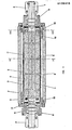
- Fig. 1 est une coupe longitudinale d'un tambour de repassage établi conformément à l'invention.
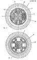
- Fig. 2 et 3 sont des coupes transversales suivant les plans respectivement indiqués en II-II et en III-III en fig. 1.
- Fig. 1 is a longitudinal section of an ironing drum established in accordance with the invention.
- Fig. 2 and 3 are cross sections along the planes respectively indicated in II-II and III-III in fig. 1.
Le tambour chauffant représenté en fig. 1 comprend essentiellement un axe 1 convenablement fixé par le moyen d'étriers 2 et autour duquel sont disposées des bobines d'excitation 3. Chacune de celles-ci est enroulée autour du pôle correspondant 4 porté par l'axe central 1, cette fixation étant assurée par le moyen de vis 5.The heating drum shown in fig. 1 essentially comprises an
Sur l'axe central 1 sont en outre disposés des paliers radiaux 6 propres à permettre la rotation d'une partie extérieure ou douille 7, entraînée par exemple par un moteur électrique, non représenté, avec interposition d'un système de courroies ou d'engrenages associé à la poulie référencée 8. Cette douille extérieure 7 supporte des barreaux 9 en un alliage métallique à haute résistivité électrique, qui constituent un circuit fermé à travers des anneaux 13, ce circuit étant similaire aux cages du type de celles utilisées dans les machines asynchrones de manière à faire fonction de circuit induit.On the
Dans ces conditions, lorsqu'on alimente convenablement en courant continu les bobines d'excitation 3 montées sur les pôles 4, on engendre un flux magnétique qui en pénétrant dans le circuit induit fermé en court-circuit lorsque la douille 7 est mise en rotation, provoque bien entendu l'obtention d'une force électromotrice dans ledit circuit induit en assurant de la sorte une circulation de courant à l'intérieur de celui-ci.Under these conditions, when the
De cette manière l'échauffement ainsi provoqué dans les barreaux 9 fait en sorte que ceux-ci cèdent de la chaleur à la douille extérieure de l'ensemble, en permettant en conséquence d'élever la température du tambour jusqu'aux valeurs désirées en fonction des besoins.In this way the heating thus caused in the
Sur le dessin on peut voir en outre qu'à l'intérieur de l'axe central 1 est ménagé un canal axial de ventilation associé à des perforations 12, afin d'opérer le refroidissement des bobines d'excitation 3. On a également prévu un empilage de tôles 10 monté autour de l'ensemble des barreaux 9, ainsi qu'une isolation thermique 11 disposée contre la face extérieure de la partie fixe en vue d'éviter qu'une partie de la chaleur engendrée à l'intérieur des barreaux 9 ne soit dispersée vers l'intérieur et non vers l'extérieur comme requis.In the drawing we can also see that inside the
Dans ces conditions l'on comprend sans peine que l'adoption de l'ensemble suivant l'invention permet de supprimer les inconvénients usuellement rencontrés dans les agencements de type connu, tels que la présence de raccords d'entrée et de sortie dans le cas du chauffage à l'aide d'un fluide chaud ou celle d'un collecteur à anneaux à balais fixes ou tournants dans le cas du chauffage par résistances électriques. On notera en particulier, en ce qui concerne ce dernier type d'appareillage, qu'on obtient une réduction considérable de la consommation d'énergie électrique à parité de chaleur fournie au tambour tournant et ce par suite du rendement très élevé du système suivant l'invention.Under these conditions it is easily understood that the adoption of the assembly according to the invention makes it possible to eliminate the drawbacks usually encountered in arrangements of known type, such as the presence of inlet and outlet fittings in the case heating using a hot fluid or that of a ring collector with fixed or rotating brushes in the case of heating by electrical resistances. It will be noted in particular, with regard to this latter type of apparatus, that a considerable reduction in the consumption of electrical energy is obtained at parity of heat supplied to the rotating drum and this as a result of the very high efficiency of the system according to the invention. 'invention.
Claims (3)
Applications Claiming Priority (2)
| Application Number | Priority Date | Filing Date | Title |
|---|---|---|---|
| IT85625/82A IT1159338B (en) | 1982-10-18 | 1982-10-18 | HEATED ROTATING CYLINDER FOR INDUCTIVE EFFECT |
| IT8562582 | 1982-10-18 |
Publications (2)
| Publication Number | Publication Date |
|---|---|
| EP0106416A2 true EP0106416A2 (en) | 1984-04-25 |
| EP0106416A3 EP0106416A3 (en) | 1986-02-19 |
Family
ID=11329199
Family Applications (1)
| Application Number | Title | Priority Date | Filing Date |
|---|---|---|---|
| EP83201478A Withdrawn EP0106416A3 (en) | 1982-10-18 | 1983-10-14 | Roller heated by induction, especially for ironing furs, fabrics or similar articles |
Country Status (2)
| Country | Link |
|---|---|
| EP (1) | EP0106416A3 (en) |
| IT (1) | IT1159338B (en) |
Cited By (5)
| Publication number | Priority date | Publication date | Assignee | Title |
|---|---|---|---|---|
| EP0195733A1 (en) * | 1985-03-20 | 1986-09-24 | Centre National De La Recherche Scientifique (Cnrs) | Induction-heated industrial machine, in particular for laundry drying and ironing |
| FR2673076A1 (en) * | 1991-02-22 | 1992-08-28 | Bianchi Vittorio | COOKING DEVICE FOR SOFT PASTE AND MACHINE FOR COOKING SOFT PASTE COMPRISING SUCH A DEVICE. |
| CN102061601B (en) * | 2009-11-18 | 2012-11-07 | 上海赛航洗涤设备有限公司 | Ironing machine drying cylinder heated by electromagnetic induction |
| CN107974817A (en) * | 2017-11-27 | 2018-05-01 | 上海乔力雅洗衣器材有限公司 | High speed rotary-drum formula press |
| CN112874966A (en) * | 2020-12-29 | 2021-06-01 | 广州市宇博纸品有限公司 | Flattening device for intelligent manufacturing equipment |
Citations (5)
| Publication number | Priority date | Publication date | Assignee | Title |
|---|---|---|---|---|
| US2273423A (en) * | 1939-06-23 | 1942-02-17 | Budd Industion Heating Inc | Electrically heated roll |
| GB978163A (en) * | 1962-03-05 | 1964-12-16 | Beanwy Electric Ltd | Improvements in or relating to rollers, calenders and like cylindrical articles |
| US3441702A (en) * | 1966-04-30 | 1969-04-29 | American Enka Corp | Method and apparatus for heating thread-like products |
| EP0022707A1 (en) * | 1979-07-09 | 1981-01-21 | CEM COMPAGNIE ELECTRO MECANIQUE Société anonyme dite: | Induction heating apparatus for long and thin products advancing continuously |
| GB2083729A (en) * | 1980-09-05 | 1982-03-24 | Kleinewefers Gmbh | Roll such as a calender roll with electromagnetic heating |
-
1982
- 1982-10-18 IT IT85625/82A patent/IT1159338B/en active
-
1983
- 1983-10-14 EP EP83201478A patent/EP0106416A3/en not_active Withdrawn
Patent Citations (5)
| Publication number | Priority date | Publication date | Assignee | Title |
|---|---|---|---|---|
| US2273423A (en) * | 1939-06-23 | 1942-02-17 | Budd Industion Heating Inc | Electrically heated roll |
| GB978163A (en) * | 1962-03-05 | 1964-12-16 | Beanwy Electric Ltd | Improvements in or relating to rollers, calenders and like cylindrical articles |
| US3441702A (en) * | 1966-04-30 | 1969-04-29 | American Enka Corp | Method and apparatus for heating thread-like products |
| EP0022707A1 (en) * | 1979-07-09 | 1981-01-21 | CEM COMPAGNIE ELECTRO MECANIQUE Société anonyme dite: | Induction heating apparatus for long and thin products advancing continuously |
| GB2083729A (en) * | 1980-09-05 | 1982-03-24 | Kleinewefers Gmbh | Roll such as a calender roll with electromagnetic heating |
Cited By (8)
| Publication number | Priority date | Publication date | Assignee | Title |
|---|---|---|---|---|
| EP0195733A1 (en) * | 1985-03-20 | 1986-09-24 | Centre National De La Recherche Scientifique (Cnrs) | Induction-heated industrial machine, in particular for laundry drying and ironing |
| FR2579233A1 (en) * | 1985-03-20 | 1986-09-26 | Centre Nat Rech Scient | INDUSTRIAL MAGNETIC INDUCTION HEATING MACHINE, ESPECIALLY FOR LAUNDRY DRYING AND IRONING |
| FR2673076A1 (en) * | 1991-02-22 | 1992-08-28 | Bianchi Vittorio | COOKING DEVICE FOR SOFT PASTE AND MACHINE FOR COOKING SOFT PASTE COMPRISING SUCH A DEVICE. |
| WO1992015183A1 (en) * | 1991-02-22 | 1992-09-03 | Synintel | Device for cooking a batter and machine for cooking batter comprising said device |
| CN102061601B (en) * | 2009-11-18 | 2012-11-07 | 上海赛航洗涤设备有限公司 | Ironing machine drying cylinder heated by electromagnetic induction |
| CN107974817A (en) * | 2017-11-27 | 2018-05-01 | 上海乔力雅洗衣器材有限公司 | High speed rotary-drum formula press |
| CN107974817B (en) * | 2017-11-27 | 2020-04-07 | 上海乔力雅洗衣器材有限公司 | High-speed drum-type ironing machine |
| CN112874966A (en) * | 2020-12-29 | 2021-06-01 | 广州市宇博纸品有限公司 | Flattening device for intelligent manufacturing equipment |
Also Published As
| Publication number | Publication date |
|---|---|
| EP0106416A3 (en) | 1986-02-19 |
| IT8285625A0 (en) | 1982-10-18 |
| IT1159338B (en) | 1987-02-25 |
Similar Documents
| Publication | Publication Date | Title |
|---|---|---|
| EP0331559B1 (en) | Configuration set of an electromagnetic brake and its supplying means | |
| FR2770941A1 (en) | COOLING SYSTEM FOR ELECTRIC MACHINE | |
| FR2478395A1 (en) | ELECTRICAL ALTERNATOR ADAPTED TO THE POWER OF THE TURBINE | |
| EP0077702A2 (en) | Converter of rotary kinetic energy into heat by generation of eddy currents | |
| FR2522898A1 (en) | ONBOARD HEATING GENERATOR FOR VEHICLES WITH LIQUID COOLING | |
| FR3049405B1 (en) | ROTATING ELECTRIC MACHINE | |
| FR2916313A1 (en) | ALTERNATOR OF VEHICLE | |
| WO2006010863A1 (en) | Water jacket for a rotary machine and rotary machine comprising same | |
| FR2462615A1 (en) | ELECTROMAGNETIC COUPLING DEVICE | |
| FR2778815A1 (en) | Magnetic heating device for automobile starter systems. | |
| FR2857520A1 (en) | ROTOR DYNAMOELECTRIC MACHINE WITH TWO COIL POLES AND CONFIGURATION WITH TWO INTERNAL FANS | |
| FR2773922A1 (en) | ELECTRIC MACHINE, PARTICULARLY A THREE-PHASE ALTERNATOR COOLED BY A LIQUID | |
| EP0106416A2 (en) | Roller heated by induction, especially for ironing furs, fabrics or similar articles | |
| FR2795253A1 (en) | DRIVE SYSTEM FOR A MOTOR VEHICLE COMPRISING A THERMAL TRANSMISSION ARRANGEMENT FOR THE ROTOR | |
| FR2797112A1 (en) | ALTERNATOR | |
| FR2857518A1 (en) | DYNAMOELECTRIC ROTOR MACHINE WITH POLES WITH TWO-COIL CLAMPS AND STATOR DRIVING | |
| FR2788899A1 (en) | Electrical generator, comprises an array of polar clutch elements located upon the rotor assembly in an axial configuration | |
| FR2857519A1 (en) | ROTOR DYNAMOELECTRIC MACHINE WITH TWO-COIL POLES AND SEGMENTED STATORIC WINDING | |
| EP2955350B1 (en) | Flow control device intended for being used in a thermoelectric generator including such a device | |
| EP3782270B1 (en) | Synchronous electrical machine | |
| FR3109679A1 (en) | Electric machine | |
| FR2551142A1 (en) | Heating and/or air conditioning installation using mechanical energy gathered on the shaft of a wind-power engine rotating at variable speed | |
| WO1998001669A1 (en) | System for managing electric energy and alternator for motor vehicle | |
| FR2756116A1 (en) | Vehicle alternator with stator coils sunk within body of stator | |
| FR2639009A1 (en) | Heating device for a motor vehicle including a heat generator |
Legal Events
| Date | Code | Title | Description |
|---|---|---|---|
| PUAI | Public reference made under article 153(3) epc to a published international application that has entered the european phase |
Free format text: ORIGINAL CODE: 0009012 |
|
| AK | Designated contracting states |
Designated state(s): AT BE CH DE FR GB IT LI LU NL SE |
|
| PUAL | Search report despatched |
Free format text: ORIGINAL CODE: 0009013 |
|
| AK | Designated contracting states |
Designated state(s): AT BE CH DE FR GB IT LI LU NL SE |
|
| STAA | Information on the status of an ep patent application or granted ep patent |
Free format text: STATUS: THE APPLICATION IS DEEMED TO BE WITHDRAWN |
|
| 18D | Application deemed to be withdrawn |
Effective date: 19861020 |