EP0102797A2 - Improvements in valves for dispensers - Google Patents
Improvements in valves for dispensers Download PDFInfo
- Publication number
- EP0102797A2 EP0102797A2 EP83304816A EP83304816A EP0102797A2 EP 0102797 A2 EP0102797 A2 EP 0102797A2 EP 83304816 A EP83304816 A EP 83304816A EP 83304816 A EP83304816 A EP 83304816A EP 0102797 A2 EP0102797 A2 EP 0102797A2
- Authority
- EP
- European Patent Office
- Prior art keywords
- valve
- sealing sleeve
- cup
- frusto
- stem
- Prior art date
- Legal status (The legal status is an assumption and is not a legal conclusion. Google has not performed a legal analysis and makes no representation as to the accuracy of the status listed.)
- Withdrawn
Links
Images
Classifications
-
- B—PERFORMING OPERATIONS; TRANSPORTING
- B65—CONVEYING; PACKING; STORING; HANDLING THIN OR FILAMENTARY MATERIAL
- B65D—CONTAINERS FOR STORAGE OR TRANSPORT OF ARTICLES OR MATERIALS, e.g. BAGS, BARRELS, BOTTLES, BOXES, CANS, CARTONS, CRATES, DRUMS, JARS, TANKS, HOPPERS, FORWARDING CONTAINERS; ACCESSORIES, CLOSURES, OR FITTINGS THEREFOR; PACKAGING ELEMENTS; PACKAGES
- B65D83/00—Containers or packages with special means for dispensing contents
- B65D83/14—Containers or packages with special means for dispensing contents for delivery of liquid or semi-liquid contents by internal gaseous pressure, i.e. aerosol containers comprising propellant for a product delivered by a propellant
- B65D83/44—Valves specially adapted therefor; Regulating devices
- B65D83/46—Tilt valves
Definitions
- the present invention relates to a valve for a pressurised dispensing container, the valve comprising a valve cup for securing to the container, a valve stem extending through an aperture in the valve cup and having a valve head and a shoulder spaced from the valve head, ports being provided in the valve stem adjacent the valve head, and a resilient sealing sleeve surrounding the valve stem and being located between the valve head and the shoulder.
- a valve such as this will hereinafter be referred to as "a valve of the type defined”.
- a problem that is encountered with a valve of the type defined is that the sealing sleeve tends to move with the valve stem because it is gripped to the stem by the pack pressure.
- valves tend either to be very difficult to open, particularly at high pressure, or to open with a snap-action, which is undesirable.
- the present invention provides a valve of the type defined in which the valve cup compris.es a generally cylindrical portion and a frusto-conical portion, the aperture being provided in the smaller end of the frusto-conical portion, and the sealing sleeve includes a frusto-conical skirt portion extending around said frusto-conical portion of the valve cup.
- the sealing sleeve preferably has a counterbore surrounding the valve stem at its end adjacent the valve head to facilitate tilting of the valve stem.
- the sealing sleeve is preferably externally chamfered at its end adjacent the valve head to facilitate tilting of the valve stem.
- the sealing sleeve may include an integral, generally cylindrical skirt portion extending around said generally cylindrical portion of the valve cup.
- the sealing sleeve may further include an integral, generally cylindrical skirt portion extending around said generally cylindrical portion of the valve cup and an integral gasket ring.
- the invention also provides a pressurised dispensing container having a valve according to the invention.
- a tilt-opening valve 10 of a kind known..to the art is shown in Figure 1.
- the valve.10 forms the end closure of a conventional pressurised dispensing container and is attachable thereto by crimping an annular collar 11 which is incorporated into metal mounting cupl2 of the valve.
- a rigid valve stem 14 and an annular sealing sleeve 15 of rubber-like material extend through a central aperture in the mounting cup 12.
- the valve stem 14 has a flanged head 16 at one end and an opposing shoulder 17 towards the other end.
- the valve stem 14 is open for dispensing fluid at its shouldered end and closed at the other end except for a number of ports 18.
- the sealing sleeve 15 is located on the valve stem 14 between the head 16 and shoulder 17.
- the valve stem 15 When the valve stem 15 is in its normal, axially-aligned position, as shown in Figure 1, the head 16 seats against the sealing sleeve 15 to seal off fluid in the container.
- the valve stem 17 When the valve stem 17 is tilted relative to the axis of the container, one region of the head 16 lifts off its seat on the sealing sleeve 15 allowing fluid to flow under pressure through ports 18 to be dispensed out of the open end of the valve stem.
- valve 10 known to the art and shown in Figure 1 incorporates a tapered counterbore 19 in the end of sealing sleeve 15 adjacent head 16 to facilitate tilting of the valve stem 14.
- the same end of the sealing sleeve 15 incorporates an external chamfer 20.
- a problem still remains, however, in that the sealing sleeve 15 will tend to move with the valve stem 14 when it is tilted, particularly at high internal pressures. This will have the effect of lifting the sealing sleeve 15 off the mounting cup 12, creating a tendency for the valve to leak.
- valves have tended to be either very difficult to open, particularly at high pressures, or have opened with an undesirable snap-action.
- a valve 110 according to the present invention is shown in Figure 2(one hundred has been added to the numberals which designate those features of the valve 110 corresponding with those known in the art.)
- the mounting cup 112 is extended by an additional frusto-conical portion 121 at one end thereof, and the sealing sleeve 115 has a complementary frusto-conical skirt 112 which is designed to extend around the portion 1212 of the mounting. cup. Because of the additional surface area which the skirt 122 of the sealing sleeve 115 presents, the sealing sleeve will be held against the mounting cup 112, by virtue of the fluid pressure,with a greater force than before. This will reduce the tendency for the sealing sleeve 115 to lift off the mouting cup 112 when the valve stem 114 is tilted.
- the additional frusto-conical portion 121 of the mounting cup 112 gives the valve 110 the ability to be able to withstand greater fluid pressures within the container than a conventional valve. This is because the frusto-conical shape is better able to withstand pressure than the traditional flat ended mounting cups.
- valve 110 easier to install on a container because of the extra space available for the crimping tool.
- valve 210 and 310 shown in Figures 3 and 4 respectively are in almost all respects identical with the valve 110 of figure 2, and like features have again been designated numerals increased by one hundred and two hundred respectively.
- the skirt 222 of the sealing sleeve 215 extends beyond the frusto-conical portion 221 of the mounting cup 222, right up to the gasket ring 213 in the annular collar 211.
- the force tending to retain the sealing sleeve 215 against the mounting cup 212 will be even greater than in the Figure 2 embodiment.
- An important advantage of the valve 210 shown in Figure 3 is that it is particularly convenient for use with fluids which should not be allowed to come into contact with the mounting cup 212.
- the skirt 322 of the sealing sleeve 315 conveniently incorporates the gasket ring 313 as an integral part.
- the sealing sleeve in this embodiment it is not possible for the sealing sleeve in this embodiment to lift off the mounting cup and cause leaks.
Abstract
A valve of the tilt opening type for pressurised dispensing containers comprises a mounting cap (112) having a cylindrical portion and a frusto-conical portion. A valve stem (114) extending through the valve cup has a surrounding sealing sleeve (115) which includes a frusto-conical skirt portion (112) which surrounds the corresponding portion of the valve cup. The valve is opened by tilting the valve stem thereby unsealing apertures (118) in the valve stem and the shape of the sealing sleeve prevents it lifting off from the mounting cup.
Description
- The present invention relates to a valve for a pressurised dispensing container, the valve comprising a valve cup for securing to the container, a valve stem extending through an aperture in the valve cup and having a valve head and a shoulder spaced from the valve head, ports being provided in the valve stem adjacent the valve head, and a resilient sealing sleeve surrounding the valve stem and being located between the valve head and the shoulder. A valve such as this will hereinafter be referred to as "a valve of the type defined". A problem that is encountered with a valve of the type defined is that the sealing sleeve tends to move with the valve stem because it is gripped to the stem by the pack pressure. This has the effect of lifting the sealing sleeve off the mounting cup creating a tendency for the valve to leak rather than open as intended. As a result known valves tend either to be very difficult to open, particularly at high pressure, or to open with a snap-action, which is undesirable.
- It is known from British Patent Specification No.1047792 to provide a tapered counterbore in the sealing sleeve of the valve in an attempt to facilitate the tilting action of the valve stem. It is also known to provide a chamfered end to the sealing member adjacent the head of the valve stem in an attempt to faciliate the tilting action of the valve stem further. However, the problem of the sealing sleeve tending to lift off the mouting cup, causing the valve to leak, still remains.
- Accordingly, the present invention provides a valve of the type defined in which the valve cup compris.es a generally cylindrical portion and a frusto-conical portion, the aperture being provided in the smaller end of the frusto-conical portion, and the sealing sleeve includes a frusto-conical skirt portion extending around said frusto-conical portion of the valve cup.
- The sealing sleeve preferably has a counterbore surrounding the valve stem at its end adjacent the valve head to facilitate tilting of the valve stem.
- The sealing sleeve is preferably externally chamfered at its end adjacent the valve head to facilitate tilting of the valve stem.
- The sealing sleeve may include an integral, generally cylindrical skirt portion extending around said generally cylindrical portion of the valve cup.
- The sealing sleeve may further include an integral, generally cylindrical skirt portion extending around said generally cylindrical portion of the valve cup and an integral gasket ring.
- The invention also provides a pressurised dispensing container having a valve according to the invention.
- By way of example, an embodiment of the present invention, together with modifications thereto, will now be described with reference to the accompanying drawings, in which:-
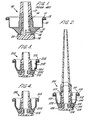
- Figure 1 is a sectional view of a prior art tilt-opening valve,
- Figure 2 is a sectional view of an embodiment of a valve according to the invention.
- Figure 3 is a sectional view of a modified form of the valve of Figure 2, and
- Figure 4 is a sectional view of a further modified form of the valve of Figure 2.
- A tilt-opening valve 10 of a kind known..to the art is shown in Figure 1. The valve.10 forms the end closure of a conventional pressurised dispensing container and is attachable thereto by crimping an
annular collar 11 which is incorporated into metal mounting cupl2 of the valve. There is asuitable gasket ring 13 to ensure a fluid tight seal for the container. Arigid valve stem 14 and anannular sealing sleeve 15 of rubber-like material extend through a central aperture in themounting cup 12. Thevalve stem 14 has aflanged head 16 at one end and an opposingshoulder 17 towards the other end. Thevalve stem 14 is open for dispensing fluid at its shouldered end and closed at the other end except for a number ofports 18. The sealingsleeve 15 is located on thevalve stem 14 between thehead 16 andshoulder 17. When thevalve stem 15 is in its normal, axially-aligned position, as shown in Figure 1, thehead 16 seats against thesealing sleeve 15 to seal off fluid in the container. When thevalve stem 17 is tilted relative to the axis of the container, one region of thehead 16 lifts off its seat on the sealingsleeve 15 allowing fluid to flow under pressure throughports 18 to be dispensed out of the open end of the valve stem. - A problem with tilt-opening valves arises in providing the valve with an easy, well-controlled tilting action for dispensing fluid whilst ensuring that an adequate seal is maintained. To this end,the valve 10 known to the art and shown in Figure 1 incorporates a
tapered counterbore 19 in the end of sealingsleeve 15adjacent head 16 to facilitate tilting of thevalve stem 14. As a further aid, the same end of the sealingsleeve 15 incorporates anexternal chamfer 20. A problem still remains, however, in that thesealing sleeve 15 will tend to move with thevalve stem 14 when it is tilted, particularly at high internal pressures. This will have the effect of lifting thesealing sleeve 15 off themounting cup 12, creating a tendency for the valve to leak. Until now, therefore valves have tended to be either very difficult to open, particularly at high pressures, or have opened with an undesirable snap-action. - A
valve 110 according to the present invention is shown in Figure 2(one hundred has been added to the numberals which designate those features of thevalve 110 corresponding with those known in the art.) - In the
valve 110 of Figure 2, themounting cup 112 is extended by an additional frusto-conical portion 121 at one end thereof, and thesealing sleeve 115 has a complementary frusto-conical skirt 112 which is designed to extend around the portion 1212 of the mounting. cup. Because of the additional surface area which theskirt 122 of thesealing sleeve 115 presents, the sealing sleeve will be held against themounting cup 112, by virtue of the fluid pressure,with a greater force than before. This will reduce the tendency for thesealing sleeve 115 to lift off themouting cup 112 when thevalve stem 114 is tilted. Moreover, the additional frusto-conical portion 121 of themounting cup 112 gives thevalve 110 the ability to be able to withstand greater fluid pressures within the container than a conventional valve. This is because the frusto-conical shape is better able to withstand pressure than the traditional flat ended mounting cups. - It has the added advantage of making the
valve 110 easier to install on a container because of the extra space available for the crimping tool. - The
valve valve 110 of figure 2, and like features have again been designated numerals increased by one hundred and two hundred respectively. In thevalve 210 of Figure 3, however, theskirt 222 of thesealing sleeve 215 extends beyond the frusto-conical portion 221 of themounting cup 222, right up to thegasket ring 213 in theannular collar 211. In this embodiment, the force tending to retain thesealing sleeve 215 against themounting cup 212 will be even greater than in the Figure 2 embodiment. An important advantage of thevalve 210 shown in Figure 3 is that it is particularly convenient for use with fluids which should not be allowed to come into contact with themounting cup 212. - In the
valve 310 of Figure 4, theskirt 322 of thesealing sleeve 315 conveniently incorporates thegasket ring 313 as an integral part. Clearly, it is not possible for the sealing sleeve in this embodiment to lift off the mounting cup and cause leaks.
Claims (6)
1. A valve for a pressurised dispensing container comprising a valve cup for securing to the container, a valve stem extending through an aperture in the valve cup and having a valve head and a shoulder spaced from the valve head, ports being provided in the valve stem adjacent the valve head, and a resilient sealing sleeve surrounding the valve stem and being located between the valve head and the shoulder, characterized in that the valve cup comprises a generally cylindrical portion (112) and a frusto-conical portion (121),the aperture being provided in the smaller end of the frusto-conical portion, and the sealing leeve (115) includes a frusto-conical portion, (122) extending around said frusto-conical portion of the valve cup.
2. A valve as claimed in claim 1 characterized in that sealing sleeve (115) has a counterbore (119) surrounding the valve stem (114) at its end adjacent the valve head (116) to facilitate tilting of the valve stem.
3. A valve as claimed in claim 1 or claim 2 characterized in that the sealing sleeve (115) is externally chamfered at its end (120) adjacent the valve head (116) to facilitate tilting of the valve -stem (114)
4. A valve as claimed in anyone of claims 1 to 3 characterized in that the sealing sleeve (215) includes an integral generally cylindrical skirt portion (222) extending around said generally cylindrical portion (212) of the valve cup.
5. A valve as claimed in any one of claims 1 to 4 characterized in that the sealing sleeve (315) further includes an integral, generally cylindrical skirt portion (322) extending around said generally cylindrical portion (312) of the valve cup and an integral gasket ring (313).
6. A pressurised dispensing container having a valve as claimed in any preceding claim.
Applications Claiming Priority (2)
| Application Number | Priority Date | Filing Date | Title |
|---|---|---|---|
| GB08225075A GB2126283B (en) | 1982-09-02 | 1982-09-02 | Improvements in valves for dispensers |
| GB8225075 | 1982-09-02 |
Publications (2)
| Publication Number | Publication Date |
|---|---|
| EP0102797A2 true EP0102797A2 (en) | 1984-03-14 |
| EP0102797A3 EP0102797A3 (en) | 1984-12-12 |
Family
ID=10532657
Family Applications (1)
| Application Number | Title | Priority Date | Filing Date |
|---|---|---|---|
| EP83304816A Withdrawn EP0102797A3 (en) | 1982-09-02 | 1983-08-19 | Improvements in valves for dispensers |
Country Status (5)
| Country | Link |
|---|---|
| EP (1) | EP0102797A3 (en) |
| JP (1) | JPS5993669A (en) |
| DK (1) | DK399283A (en) |
| GB (1) | GB2126283B (en) |
| ZA (1) | ZA836499B (en) |
Cited By (5)
| Publication number | Priority date | Publication date | Assignee | Title |
|---|---|---|---|---|
| EP0816254A1 (en) * | 1996-07-05 | 1998-01-07 | Menken Dairy Food B.V. | Actuating assembly comprising an enveloping member, an enveloping member and an aerosol can comprising such an actuating assembly |
| WO1999026511A1 (en) * | 1997-11-21 | 1999-06-03 | The Procter & Gamble Company | Applicator systems |
| US6505986B1 (en) | 1997-11-21 | 2003-01-14 | The Procter & Gamble Company | Applicator systems |
| EP2481688A1 (en) | 2011-01-27 | 2012-08-01 | Altachem Holdings NV | Dispensing aerosol valve for pressurized container |
| EP2487120A1 (en) | 2011-02-10 | 2012-08-15 | Altachem N.V. | Dispensing aerosol valve for pressurized container, dispensing adapter therefor, and assembly of a pressurized container with an adapter |
Citations (4)
| Publication number | Priority date | Publication date | Assignee | Title |
|---|---|---|---|---|
| US2965271A (en) * | 1956-12-27 | 1960-12-20 | Dev Res Inc | Valve body incorporating mounting cup mask and gasket |
| US3048307A (en) * | 1959-08-24 | 1962-08-07 | Michel David Daniel | Device for dispensing aerated products |
| GB1047792A (en) * | 1964-01-30 | 1966-11-09 | Clayton Corp Of Delaware | Tilt-opening valves for dispensers |
| US3299960A (en) * | 1964-10-30 | 1967-01-24 | Gottfried F Stern | Valve |
Family Cites Families (3)
| Publication number | Priority date | Publication date | Assignee | Title |
|---|---|---|---|---|
| US3920165A (en) * | 1974-08-16 | 1975-11-18 | Robert S Schultz | Automatic tip-seal valve |
| US4073398A (en) * | 1977-01-28 | 1978-02-14 | The Risdon Manufacturing Company | Snap-lock device for securing a dispensing mechanism to a container |
| CA1060396A (en) * | 1977-01-28 | 1979-08-14 | Risdon Manufacturing Company (The) | Aerosol container construction and production methods |
-
1982
- 1982-09-02 GB GB08225075A patent/GB2126283B/en not_active Expired
-
1983
- 1983-08-19 EP EP83304816A patent/EP0102797A3/en not_active Withdrawn
- 1983-09-01 ZA ZA836499A patent/ZA836499B/en unknown
- 1983-09-01 DK DK399283A patent/DK399283A/en not_active Application Discontinuation
- 1983-09-01 JP JP58161825A patent/JPS5993669A/en active Pending
Patent Citations (4)
| Publication number | Priority date | Publication date | Assignee | Title |
|---|---|---|---|---|
| US2965271A (en) * | 1956-12-27 | 1960-12-20 | Dev Res Inc | Valve body incorporating mounting cup mask and gasket |
| US3048307A (en) * | 1959-08-24 | 1962-08-07 | Michel David Daniel | Device for dispensing aerated products |
| GB1047792A (en) * | 1964-01-30 | 1966-11-09 | Clayton Corp Of Delaware | Tilt-opening valves for dispensers |
| US3299960A (en) * | 1964-10-30 | 1967-01-24 | Gottfried F Stern | Valve |
Cited By (12)
| Publication number | Priority date | Publication date | Assignee | Title |
|---|---|---|---|---|
| EP0816254A1 (en) * | 1996-07-05 | 1998-01-07 | Menken Dairy Food B.V. | Actuating assembly comprising an enveloping member, an enveloping member and an aerosol can comprising such an actuating assembly |
| NL1003521C2 (en) * | 1996-07-05 | 1998-01-12 | Menken Dairy Food B V | Operating assembly, a casing part intended for said operating assembly and an aerosol with such an operating assembly. |
| WO1999026511A1 (en) * | 1997-11-21 | 1999-06-03 | The Procter & Gamble Company | Applicator systems |
| US6505986B1 (en) | 1997-11-21 | 2003-01-14 | The Procter & Gamble Company | Applicator systems |
| EP2481688A1 (en) | 2011-01-27 | 2012-08-01 | Altachem Holdings NV | Dispensing aerosol valve for pressurized container |
| WO2012101061A1 (en) | 2011-01-27 | 2012-08-02 | Altachem Nv | Valve for an aerosol container |
| US9399544B2 (en) | 2011-01-27 | 2016-07-26 | Altachem Nv | Valve for an aerosol container |
| EP2487120A1 (en) | 2011-02-10 | 2012-08-15 | Altachem N.V. | Dispensing aerosol valve for pressurized container, dispensing adapter therefor, and assembly of a pressurized container with an adapter |
| WO2012107276A1 (en) | 2011-02-10 | 2012-08-16 | Altachem Nv | Dispensing aerosol valve for pressurized container, dispensing adapter therefor, and assembly of a pressurized container with an adapter |
| CN103492286A (en) * | 2011-02-10 | 2014-01-01 | 艾尔塔彻姆公司 | Dispensing aerosol valve for pressurized container, dispensing adapter therefor, and assembly of a pressurized container with an adapter |
| CN103492286B (en) * | 2011-02-10 | 2016-03-02 | 艾尔塔彻姆公司 | Distribute aerosol valve, distribute the assembly of adapter and pressurizing vessel and adapter |
| RU2604443C2 (en) * | 2011-02-10 | 2016-12-10 | Альтакем НВ | Aerosol dispenser valve for pressure vessel, dispenser adapter for it and assembly of pressure vessel with adapter |
Also Published As
| Publication number | Publication date |
|---|---|
| DK399283D0 (en) | 1983-09-01 |
| ZA836499B (en) | 1985-04-24 |
| EP0102797A3 (en) | 1984-12-12 |
| GB2126283B (en) | 1986-03-05 |
| DK399283A (en) | 1984-03-03 |
| GB2126283A (en) | 1984-03-21 |
| JPS5993669A (en) | 1984-05-30 |
Similar Documents
| Publication | Publication Date | Title |
|---|---|---|
| CA1316505C (en) | Valve for a container for dispensing a pressurized fluid | |
| US2965270A (en) | Dispensing valve having spring of elastic material | |
| KR100198691B1 (en) | High volume fuel vapor release valve | |
| US5188144A (en) | Plug valve | |
| US4768664A (en) | Insulating jug having an elastic seal | |
| EP0102797A2 (en) | Improvements in valves for dispensers | |
| US5456447A (en) | Valve assembly | |
| WO2002057671A1 (en) | Pressure relief device with one piece gasket | |
| GB2286651A (en) | Rotary valve | |
| US4512587A (en) | Aerosol cannister fitting | |
| US4537214A (en) | Single seal pipeline tapping fixture having secure valve | |
| US5603425A (en) | Radiator cap | |
| CA1225567A (en) | Erosion resistant soft seated valve trim | |
| US20030045841A1 (en) | Feeding device with secondary stop tab | |
| JPH0245076B2 (en) | ||
| US4659060A (en) | Stem tip seal | |
| GB2064652A (en) | Pressure vessels | |
| US4014513A (en) | Cylindrical plug valve | |
| US1051688A (en) | Can and similar receptacle. | |
| US2657704A (en) | Valve | |
| GB2177185A (en) | Liquid dispensing tap | |
| EP0715594B1 (en) | An improved aerosol valve | |
| JPS6278065A (en) | Fuel tank cap | |
| US3618832A (en) | Fast fill valve assembly for pressurized dispensing package | |
| US4708161A (en) | Plug valve |
Legal Events
| Date | Code | Title | Description |
|---|---|---|---|
| PUAI | Public reference made under article 153(3) epc to a published international application that has entered the european phase |
Free format text: ORIGINAL CODE: 0009012 |
|
| AK | Designated contracting states |
Designated state(s): AT BE CH DE FR IT LI NL SE |
|
| PUAL | Search report despatched |
Free format text: ORIGINAL CODE: 0009013 |
|
| AK | Designated contracting states |
Designated state(s): AT BE CH DE FR IT LI NL SE |
|
| 17P | Request for examination filed |
Effective date: 19850403 |
|
| STAA | Information on the status of an ep patent application or granted ep patent |
Free format text: STATUS: THE APPLICATION IS DEEMED TO BE WITHDRAWN |
|
| 18D | Application deemed to be withdrawn |
Effective date: 19860406 |
|
| RIN1 | Information on inventor provided before grant (corrected) |
Inventor name: BURT, PETER COLIN WESTON |