EP0101012B1 - Detachable balloon catheter device - Google Patents
Detachable balloon catheter device Download PDFInfo
- Publication number
- EP0101012B1 EP0101012B1 EP83107646A EP83107646A EP0101012B1 EP 0101012 B1 EP0101012 B1 EP 0101012B1 EP 83107646 A EP83107646 A EP 83107646A EP 83107646 A EP83107646 A EP 83107646A EP 0101012 B1 EP0101012 B1 EP 0101012B1
- Authority
- EP
- European Patent Office
- Prior art keywords
- cannula
- balloon
- plug
- fluid
- opening
- Prior art date
- Legal status (The legal status is an assumption and is not a legal conclusion. Google has not performed a legal analysis and makes no representation as to the accuracy of the status listed.)
- Expired
Links
Images


Classifications
-
- A—HUMAN NECESSITIES
- A61—MEDICAL OR VETERINARY SCIENCE; HYGIENE
- A61B—DIAGNOSIS; SURGERY; IDENTIFICATION
- A61B17/00—Surgical instruments, devices or methods, e.g. tourniquets
- A61B17/12—Surgical instruments, devices or methods, e.g. tourniquets for ligaturing or otherwise compressing tubular parts of the body, e.g. blood vessels, umbilical cord
- A61B17/12022—Occluding by internal devices, e.g. balloons or releasable wires
- A61B17/12099—Occluding by internal devices, e.g. balloons or releasable wires characterised by the location of the occluder
- A61B17/12109—Occluding by internal devices, e.g. balloons or releasable wires characterised by the location of the occluder in a blood vessel
-
- A—HUMAN NECESSITIES
- A61—MEDICAL OR VETERINARY SCIENCE; HYGIENE
- A61B—DIAGNOSIS; SURGERY; IDENTIFICATION
- A61B17/00—Surgical instruments, devices or methods, e.g. tourniquets
- A61B17/12—Surgical instruments, devices or methods, e.g. tourniquets for ligaturing or otherwise compressing tubular parts of the body, e.g. blood vessels, umbilical cord
- A61B17/12022—Occluding by internal devices, e.g. balloons or releasable wires
- A61B17/12131—Occluding by internal devices, e.g. balloons or releasable wires characterised by the type of occluding device
- A61B17/12136—Balloons
-
- A—HUMAN NECESSITIES
- A61—MEDICAL OR VETERINARY SCIENCE; HYGIENE
- A61M—DEVICES FOR INTRODUCING MEDIA INTO, OR ONTO, THE BODY; DEVICES FOR TRANSDUCING BODY MEDIA OR FOR TAKING MEDIA FROM THE BODY; DEVICES FOR PRODUCING OR ENDING SLEEP OR STUPOR
- A61M25/00—Catheters; Hollow probes
- A61M25/10—Balloon catheters
- A61M2025/1043—Balloon catheters with special features or adapted for special applications
- A61M2025/1054—Balloon catheters with special features or adapted for special applications having detachable or disposable balloons
Definitions
- the present invention generally relates to a detachable balloon catheter device comprising:
- Balloon catheters have been used for many years to carry out medical procedures in blood vessels, body cavities and the like.
- Detachable balloon catheters are rather recent developments directed to more particular medical procedures related to vascular occlusion or the like interventional techniques.
- Some of the early work in detachable balloon catheters is traced to pioneering activities of F.A. Serbinenko, M.D., and Gerard Debrun, M.D. See, e.g., Serbinenko, F.A., "Balloon Catheterization and Occlusion of Major Cerebral Vessels", Journal of Neurosurgery, Vol. 41, pp. 125-145, Aug.
- detachable balloon catheters have been employed for therapeutic embolization by R.I. White, M.D. See, e.g., White et al. "Therapeutic Embolization With Detachable Silicone Balloons", 241 Journal of the American Medical Association, pp. 1257-1260, Mar. 23, 1979.
- Detachable balloon catheters have also been used for carotid- cavernous sinus fistulas and other AV fistulas in the head.
- Dr. White has also employed a detachable balloon catheter for the occlusion of the internal spermatic vein in the treatment of var- icoceles.
- a detachable balloon catheter is available from Becton, Dickinson and Company, Rutherford, New Jersey, known as the B-D MINIBALLOONTM Detachable Balloon System.
- the inflatable balloon is attached to an introducer catheter or like cannula, and by angiographic techniques, the balloon and cannula are inserted into the artery until the balloon reaches the desired site.
- the balloon is inflated at that site by pressurized fluid entering the balloon through the cannula.
- it is desired to leave the inflated balloon in position while detaching the cannula.
- Difficulties arise because the cannula must be detached from the balloon, located at a remote site in the body, while the balloon remains in position, and, inflated.
- Various techniques have been proposed to assure this capability of detachment while leaving the balloon inflated in situ.
- the balloon catheter device of the present invention is characterized in that the lumen of the resilient tubular cannula is closed at the distal end thereof, that the distal portion of said cannula includes the fluid passage means through the circumferential wall thereof in communication with said lumen and that said cannula is slidable proximally through said opening when the balloon is inflated to disengage said plug therefrom and position the plug in fluid-tight engagement in said opening interiorly of said balloon to thereby detach said cannula from said inflated balloon.
- the present invention provides a straightforward technique for inflating a detachable balloon positioned on the cannula, while permitting ready sealing of the inflated balloon and providing for detachment of the cannula thereafter.
- the present invention desirably minimizes functional parts and complexity of structure.
- the straightforward design and structure of the present invention allows for economy of manufacture, convenience in use and minimal training for the operator who will be using this device.
- cost savings to the patient should be achieved, as well as to the manufacturer.
- Device 10 is comprised of three major elements: a cannula 12, an inflatable balloon 14 and a detachable plug 16.
- cannula 12 it is preferably, but not limited to, a resilient tubular member with a lumen 18 extending therethrough.
- the flexibility feature is preferred inasmuch as this catheter device is expected to weave a tortuous path to a remote site inside a blood vessel.
- cannula 12 has a portion at its proximal end (nearest the operator) adapted for connection to a source of external fluid which is to be utilized for pressurizing the balloon to inflate same.
- a source of external fluid which is to be utilized for pressurizing the balloon to inflate same.
- the distal end 19 of cannula 12 is provided with a stopper 20 so as to seal the lumen closed.
- Stopper 20 may be affixed by adhesive means, thermoplastic melting techniques or the like. On the other hand, stopper 20 may be eliminated if cannula 12 is fabricated with distal end 19 closed. In any event, for purposes of the embodiment being described, the distal end of lumen 18 should be sealed closed. Spaced a short distance proximally from the distal end of cannula 12 is a pair of holes 21 through the circumferential wall of the cannula communicating with the lumen. As will be described hereinafter, holes 21 are for the flow of pressurized fluid into the interior of balloon 14. It is appreciated that the number of such holes is a matter of choice or design; for balance, the present embodiment has two such holes.
- Plug 16 is detachably connected to distal portion 19 of the cannula.
- plug 16 includes a cup-shaped portion 24 and a block-shaped portion 25.
- the overall configuration of plug 16 is cylindrical, with block portion 25 being preferably solid.
- block portion 25 is preferably tapered so that its largest diameter 26 is at its distal end thereof.
- Cup-shaped portion 24 is fit over distal end 19 of the cannula by frictional engagement around the outer circumferential wall of the cannula. It can be seen particularly in Fig. 2 that cup-shaped portion 24 does not cover or block holes 21 in the distal portion of the cannula.
- Inflatable balloon 14 may be provided as a unitary, one-piece member. However, it is sometimes more convenient to fabricate balloon 14 with two open ends, one of which will form the distal end of the balloon catheter device. This end of the balloon may be sealed closed with a plug of material 28 similar to the material out of which the balloon is fabricated. Plug material 28 may be affixed to the distal end of balloon 14 by adhesives, thermoplastic melting or the like. A sleeve-like extension 29 tapers inwardly so that the opening 30 at the proximal end of the balloon is in a frictional and fluid-tight engagement around the outer circumferential wall of the cannula. As can be seen in Fig.
- sleeve-like extension 29 makes contact to the cannula on the proximal side of holes 21 in the distal end of the cannula.
- This frictional, fluid-tight engagement of the balloon to the cannula is achieved by a controlled tight fit of opening 30 around the circumferential wall of the cannula. Additional mechanical clamps, tie-strings or the like are not required in the present invention.
- plug 16 is preferably engaged only to the distal end of the cannula and remains disconnected to any interior surface of the balloon.
- Suitable materials may be employed to manufacture the cannula, balloon and plug of the present invention.
- Elastomeric material for all of the aforementioned elements is the material of choice.
- the flexible cannula may be made of polyurethane, polyethylene or combinations thereof. It is also understood that the cannula may have a single lumen extending therethrough, as described above in the preferred embodiment, or may have multiple lumens which may facilitate the removal of the balloon from the cannula during use.
- the inflatable balloon is preferably made of silicone rubber, although other elastomeric materials such as latex rubber, polyurethane and the like may be used. Furthermore, it is preferred to make the detachable plug out of the same material as the inflatable balloon for compatability purposes.
- a detachable balloon catheter device as herein described may be used, for example, in blood vessels up to 4 mm in diameter.
- the outside diameter of the uninflated balloon typically may be 1 mm.
- the present invention contemplates balloons of different sizes, with the foregoing example being merely illustrative of one use of the invention herein.
- Figs. 4 to 7 depict the detachable balloon catheter device, as described above, in use in a blood vessel.
- detachable balloon catheter device 10 is seen inside a blood vessel 40.
- the proximal end of cannula 12 is connected to a source of fluid (not shown) outside of the body.
- balloon 14 has been partially inflated during the insertion procedure. Fluid is delivered to the interior of balloon 14 from the fluid source outside of the body, through cannula 12 and through holes 21 in the distal portion of the cannula. Partial inflation of balloon 14 has been found to cause a "parachute" effect with the blood flow pulling the balloon and cannula, connected thereto, within the blood vessel.
- balloon 14 engages the walls of blood vessel 40 in such a manner as to provide an occlusion to thereby prevent the flow of blood therethrough past the inflated balloon.
- This tight engagement of the balloon is illustrated in Figs. 5 to 7.
- cannula 12 is withdrawn by the operator in a proximal direction as illustrated by the arrow in Fig. 6. This proximal withdrawing movement of the cannula causes the cannula to slide outwardly, or proximally, relative to the inflated balloon which remains tightly engaged to the walls of blood vessel 40.
- plug 16 With reference to Fig. 7, continued proximal withdrawl of cannula 12 by the operator causes plug 16 to become tightly engaged within opening 30 from the interior side of inflated balloon 14.
- the preferred tapered nature of plug 16 contributes to the effective seal of opening 30.
- the tapered surfaces of plug 16 serve to prevent further proximal movement of plug 16 through opening 30 in the balloon.
- continued proximal withdrawal of cannula 12 acts to detach distal portion 19 from cup-shaped portion 24 of the plug. Once this detachment of the cannula from the balloon and plug is accomplished, the operator may completely withdraw the cannula from the blood vessel leaving the inflated balloon at the desired site.
- a detachable balloon catheter device has been provided in accordance with the present invention which readily facilitates the inflation and detachment of a balloon device which is intended to occlude a vessel.
- the detachable balloon catheter device herein embodies a minimal number of elements in its structure for complete operative functionability. It is economical to manufacture and straightforward to use.
- the catheter device herein represents a significant improvement in the field of detachable balloon catheter devices.
Description
- The present invention generally relates to a detachable balloon catheter device comprising:
- a resilient tubular cannula with a lumen extending therethrough having a proximal portion adapted for connection to a source of external fluid, the distal portion of said cannula including fluid passage means;
- a plug detachably connected to the distal portion of said cannula without blocking said fluid passage means; and
- an inflatable balloon detachably connected to the distal portion of said cannula covering said plug and said fluid passage means, said balloon having an opening normally in fluid-tight engagement around said cannula, said cannula being slidable proximally through said opening when the balloon is inflated, said plug being disengaged therefrom and positioned in fluid-tight engagement in said opening.
- Balloon catheters have been used for many years to carry out medical procedures in blood vessels, body cavities and the like. Detachable balloon catheters, however, are rather recent developments directed to more particular medical procedures related to vascular occlusion or the like interventional techniques. Some of the early work in detachable balloon catheters is traced to pioneering activities of F.A. Serbinenko, M.D., and Gerard Debrun, M.D. See, e.g., Serbinenko, F.A., "Balloon Catheterization and Occlusion of Major Cerebral Vessels", Journal of Neurosurgery, Vol. 41, pp. 125-145, Aug. 1974, and Debrun et al., "Inflatable And Released Balloon Technique Experimentation In Dog - Application In Man", 9 Neuroradiology, p. 267, 1975. Additional activities were carried on in the 1970's by Paul Pevsner, M.D. See, e.g. Pevsner, P.H., "Micro-Balloon Catheter For Superselective Angiography And Therapeutic Occlusion", 128 American Journal of Roentgenology, p. 225, 1977; and US-A-4,085,757.
- A significant use of detachable balloon catheters is in the therapeutic occlusion of arteries. For instance, detachable silicone balloons have been employed for therapeutic embolization by R.I. White, M.D. See, e.g., White et al. "Therapeutic Embolization With Detachable Silicone Balloons", 241 Journal of the American Medical Association, pp. 1257-1260, Mar. 23, 1979. Detachable balloon catheters have also been used for carotid- cavernous sinus fistulas and other AV fistulas in the head. Dr. White has also employed a detachable balloon catheter for the occlusion of the internal spermatic vein in the treatment of var- icoceles. At present, a detachable balloon catheter is available from Becton, Dickinson and Company, Rutherford, New Jersey, known as the B-D MINIBALLOONTM Detachable Balloon System.
- One of the difficulties encountered in utilizing a detachable balloon catheter device lies in the detaching function. Initially, the inflatable balloon is attached to an introducer catheter or like cannula, and by angiographic techniques, the balloon and cannula are inserted into the artery until the balloon reaches the desired site. The balloon is inflated at that site by pressurized fluid entering the balloon through the cannula. Thereafter, it is desired to leave the inflated balloon in position while detaching the cannula. Difficulties arise because the cannula must be detached from the balloon, located at a remote site in the body, while the balloon remains in position, and, inflated. Various techniques have been proposed to assure this capability of detachment while leaving the balloon inflated in situ.
- One recent suggestion for improving the detachment capability of detachable balloon catheters is found in US-A-4,311,146. This patented device relies upon longitudinal expansion of the balloon in the blood vessel to literally pull a valve longitudinally into the balloon inflating passage after the balloon has been inflated with sufficient fluid. The movement of this valve is described as being achieved automatically to effect a closure of the inflated balloon, whereupon the introducer catheter may be detached. It should be pointed out, however, that such automatic closure of the inflated balloon deprives the operator of flexibility in the manipulation of the balloon if it should be inflated inadvertently or if adjustments may be required in the location of the balloon at a remote site in the body. Accordingly, in this rather new field of detachable balloon catheters, improvements are still being sought which contribute to the ability to inflate the balloon, detach the catheter therefrom, while assuring that the inflated balloon remains inflated at the desired site. In addition, ease of use, simplicity of structure, economies of manufacture and operator training are factors which must be considered when improving a detachable balloon catheter device. It is to such improvements that the present invention is directed.
- The balloon catheter device of the present invention is characterized in that the lumen of the resilient tubular cannula is closed at the distal end thereof, that the distal portion of said cannula includes the fluid passage means through the circumferential wall thereof in communication with said lumen and that said cannula is slidable proximally through said opening when the balloon is inflated to disengage said plug therefrom and position the plug in fluid-tight engagement in said opening interiorly of said balloon to thereby detach said cannula from said inflated balloon.
- In accordance with the principles of the present invention, a number of objectives are advantageously achieved. For instance, the present invention provides a straightforward technique for inflating a detachable balloon positioned on the cannula, while permitting ready sealing of the inflated balloon and providing for detachment of the cannula thereafter. In addition to these functional advantages, the present invention desirably minimizes functional parts and complexity of structure. The straightforward design and structure of the present invention allows for economy of manufacture, convenience in use and minimal training for the operator who will be using this device. As a result of the structure of the present invention, cost savings to the patient should be achieved, as well as to the manufacturer.
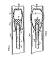
- Fig. 1 is a perspective view illustrating the balloon end of the preferred detachable balloon catheter device of the present invention;
- Fig. 2 is a cross-sectional view of the detachable balloon catheter device taken along line 2-2 of Fig. 1;
- Fig. 3 is an enlarged perspective view of the preferred detachable plug utilized in conjunction with the embodiment illustrated in Figs. 1 and 2;
- Fig. 4 is a cross-sectional view of the preferred detachable balloon catheter device positioned within a blood vessel and illustrating the balloon in a state of partial inflation;
- Fig. 5 is a cross-sectional view of the detachable balloon device illustrating the balloon completely inflated at the desired site in the blood vessel;
- Fig. 6 is a cross-sectional view of the preferred detachable balloon catheter device illustrating the withdrawal of the cannula in a proximal direction until the plug is positioned in and seals the opening in the balloon; and
- Fig. 7 is a cross-sectional view of the preferred detachable balloon catheter device illustrating in sequence the sealing of the opening of the balloon and the detachment of the cannula from the balloon after it is sealed in the inflated condition.
- While this invention is satisfied by embodiments in many different forms, there is shown in the drawings and will herein be described in detail a preferred embodiment of the invention, with the understanding that the present disclosure is to be considered as exemplary of the principles of the invention and is not intended to limit the invention to the embodiment illustrated.
- Adverting to the drawings, and Figs. 1 and 2 in particular, there is illustrated the preferred detachable
balloon catheter device 10 of the present invention.Device 10 is comprised of three major elements: acannula 12, aninflatable balloon 14 and adetachable plug 16. - Turning first to
cannula 12, it is preferably, but not limited to, a resilient tubular member with alumen 18 extending therethrough. The flexibility feature is preferred inasmuch as this catheter device is expected to weave a tortuous path to a remote site inside a blood vessel. While not shown in the drawings,cannula 12 has a portion at its proximal end (nearest the operator) adapted for connection to a source of external fluid which is to be utilized for pressurizing the balloon to inflate same. Such a connection to the proximal portion of the cannula is described in U.S. Patent No. 4,243,033. Thedistal end 19 ofcannula 12 is provided with astopper 20 so as to seal the lumen closed.Stopper 20 may be affixed by adhesive means, thermoplastic melting techniques or the like. On the other hand,stopper 20 may be eliminated ifcannula 12 is fabricated withdistal end 19 closed. In any event, for purposes of the embodiment being described, the distal end oflumen 18 should be sealed closed. Spaced a short distance proximally from the distal end ofcannula 12 is a pair ofholes 21 through the circumferential wall of the cannula communicating with the lumen. As will be described hereinafter,holes 21 are for the flow of pressurized fluid into the interior ofballoon 14. It is appreciated that the number of such holes is a matter of choice or design; for balance, the present embodiment has two such holes. -
Plug 16 is detachably connected todistal portion 19 of the cannula. As seen in Fig. 3, taken in conjunction with Fig. 2,plug 16 includes a cup-shaped portion 24 and a block-shaped portion 25. The overall configuration ofplug 16 is cylindrical, withblock portion 25 being preferably solid. In addition,block portion 25 is preferably tapered so that itslargest diameter 26 is at its distal end thereof. Cup-shaped portion 24 is fit overdistal end 19 of the cannula by frictional engagement around the outer circumferential wall of the cannula. It can be seen particularly in Fig. 2 that cup-shapedportion 24 does not cover or blockholes 21 in the distal portion of the cannula. -
Inflatable balloon 14 may be provided as a unitary, one-piece member. However, it is sometimes more convenient to fabricateballoon 14 with two open ends, one of which will form the distal end of the balloon catheter device. This end of the balloon may be sealed closed with a plug ofmaterial 28 similar to the material out of which the balloon is fabricated.Plug material 28 may be affixed to the distal end ofballoon 14 by adhesives, thermoplastic melting or the like. A sleeve-like extension 29 tapers inwardly so that theopening 30 at the proximal end of the balloon is in a frictional and fluid-tight engagement around the outer circumferential wall of the cannula. As can be seen in Fig. 2, sleeve-like extension 29 makes contact to the cannula on the proximal side ofholes 21 in the distal end of the cannula. This frictional, fluid-tight engagement of the balloon to the cannula is achieved by a controlled tight fit of opening 30 around the circumferential wall of the cannula. Additional mechanical clamps, tie-strings or the like are not required in the present invention. Moreover, it should be pointed out thatplug 16 is preferably engaged only to the distal end of the cannula and remains disconnected to any interior surface of the balloon. - Suitable materials may be employed to manufacture the cannula, balloon and plug of the present invention. Elastomeric material for all of the aforementioned elements is the material of choice. For example, the flexible cannula may be made of polyurethane, polyethylene or combinations thereof. It is also understood that the cannula may have a single lumen extending therethrough, as described above in the preferred embodiment, or may have multiple lumens which may facilitate the removal of the balloon from the cannula during use. The inflatable balloon is preferably made of silicone rubber, although other elastomeric materials such as latex rubber, polyurethane and the like may be used. Furthermore, it is preferred to make the detachable plug out of the same material as the inflatable balloon for compatability purposes. To appreciate the need to have simplicity and straightforwardness of structure, a detachable balloon catheter device as herein described may be used, for example, in blood vessels up to 4 mm in diameter. For such use, the outside diameter of the uninflated balloon typically may be 1 mm. It is understood that the present invention, of course, contemplates balloons of different sizes, with the foregoing example being merely illustrative of one use of the invention herein.
- Figs. 4 to 7 depict the detachable balloon catheter device, as described above, in use in a blood vessel. Referring first to Fig. 4, detachable
balloon catheter device 10 is seen inside ablood vessel 40. The proximal end ofcannula 12 is connected to a source of fluid (not shown) outside of the body. As can be seen in Fig. 4,balloon 14 has been partially inflated during the insertion procedure. Fluid is delivered to the interior ofballoon 14 from the fluid source outside of the body, throughcannula 12 and throughholes 21 in the distal portion of the cannula. Partial inflation ofballoon 14 has been found to cause a "parachute" effect with the blood flow pulling the balloon and cannula, connected thereto, within the blood vessel. One technique for inserting the balloon catheter device such as described herein is found in U.S. Patent No. 4,243,033. When the balloon is at the desired site inblood vessel 40, it is fully inflated by delivering fluid, under pressure, from the fluid source outside of the body, as mentioned above. Fluid travels alonglumen 18, and since its distal end is blocked bystopper 20, fluid exitsholes 21 and enters the interior ofballoon 14 thereby inflating same. This inflation step is illustrated in Fig. 5. Whileballoon 14 is being inflated,cannula 12 and plug 16 remain in a fixed position relative to the balloon. Inflation of the balloon also has no effect onplug 16 which remains connected to the distal end of the cannula. - Once
balloon 14 is properly inflated, it engages the walls ofblood vessel 40 in such a manner as to provide an occlusion to thereby prevent the flow of blood therethrough past the inflated balloon. This tight engagement of the balloon is illustrated in Figs. 5 to 7. Referring now to Fig. 6, after the balloon is fully inflated at the desired site in the blood vessel,cannula 12 is withdrawn by the operator in a proximal direction as illustrated by the arrow in Fig. 6. This proximal withdrawing movement of the cannula causes the cannula to slide outwardly, or proximally, relative to the inflated balloon which remains tightly engaged to the walls ofblood vessel 40. Facilitating this sliding outward movement of the cannula is the lifting effect on sleeve-like extension 29 caused by inflation of the balloon. The fluid which inflates the balloon wets the surface of the cannula at its distal end, including the mating, junctional surfaces of the sleeve-like extension and the circumferential wall of the cannula. As a result, a lubricious effect occurs facilitating the sliding movement of the cannula through opening 30 in sleeve-like extension 29 of the balloon. Thus, whencannula 12 is withdrawn proximally by the operator, inflated balloon remains fixed in the blood vessel, and plug 16 becomes positioned within opening 30 from the interior side of the balloon. Onceplug 16 is positioned within opening 30, a closure is effected thereby preventing the escape of fluid from the balloon so that the balloon may remain inflated. - With reference to Fig. 7, continued proximal withdrawl of
cannula 12 by the operator causes plug 16 to become tightly engaged withinopening 30 from the interior side ofinflated balloon 14. The preferred tapered nature ofplug 16 contributes to the effective seal ofopening 30. In addition, the tapered surfaces ofplug 16 serve to prevent further proximal movement ofplug 16 throughopening 30 in the balloon. As a result, continued proximal withdrawal ofcannula 12 acts to detachdistal portion 19 from cup-shapedportion 24 of the plug. Once this detachment of the cannula from the balloon and plug is accomplished, the operator may completely withdraw the cannula from the blood vessel leaving the inflated balloon at the desired site. - Thus, a detachable balloon catheter device has been provided in accordance with the present invention which readily facilitates the inflation and detachment of a balloon device which is intended to occlude a vessel. The detachable balloon catheter device herein embodies a minimal number of elements in its structure for complete operative functionability. It is economical to manufacture and straightforward to use. The catheter device herein represents a significant improvement in the field of detachable balloon catheter devices.
Claims (9)
Applications Claiming Priority (2)
| Application Number | Priority Date | Filing Date | Title |
|---|---|---|---|
| US06/408,344 US4441495A (en) | 1982-08-16 | 1982-08-16 | Detachable balloon catheter device and method of use |
| US408344 | 1982-08-16 |
Publications (3)
| Publication Number | Publication Date |
|---|---|
| EP0101012A2 EP0101012A2 (en) | 1984-02-22 |
| EP0101012A3 EP0101012A3 (en) | 1984-09-12 |
| EP0101012B1 true EP0101012B1 (en) | 1986-06-04 |
Family
ID=23615890
Family Applications (1)
| Application Number | Title | Priority Date | Filing Date |
|---|---|---|---|
| EP83107646A Expired EP0101012B1 (en) | 1982-08-16 | 1983-08-03 | Detachable balloon catheter device |
Country Status (5)
| Country | Link |
|---|---|
| US (1) | US4441495A (en) |
| EP (1) | EP0101012B1 (en) |
| JP (1) | JPS5934269A (en) |
| CA (1) | CA1194750A (en) |
| DE (1) | DE3363929D1 (en) |
Families Citing this family (112)
| Publication number | Priority date | Publication date | Assignee | Title |
|---|---|---|---|---|
| US4697584A (en) * | 1984-10-12 | 1987-10-06 | Darrel W. Haynes | Device and method for plugging an intramedullary bone canal |
| US4686973A (en) * | 1984-10-12 | 1987-08-18 | Dow Corning Corporation | Method of making an intramedullary bone plug and bone plug made thereby |
| JPS61168338A (en) * | 1985-01-22 | 1986-07-30 | 旭光学工業株式会社 | Balloon attached to ultrasonic endoscope |
| US4705517A (en) * | 1985-09-03 | 1987-11-10 | Becton, Dickinson And Company | Percutaneously deliverable intravascular occlusion prosthesis |
| US4662885A (en) * | 1985-09-03 | 1987-05-05 | Becton, Dickinson And Company | Percutaneously deliverable intravascular filter prosthesis |
| DE3790493T1 (en) * | 1986-10-29 | 1988-10-06 | Okamoto Industries, Inc. | ENDOSCOPE OR BALLOON FOR USING AN OPTICAL FIBER AND METHOD FOR PRODUCING THE SAME |
| JPS64908U (en) * | 1987-06-22 | 1989-01-06 | ||
| US4773908A (en) * | 1986-12-18 | 1988-09-27 | Hilton Becker | Filling tube and seal construction for inflatable implant |
| US4813935A (en) * | 1987-07-27 | 1989-03-21 | Habley Medical Technology Corporation | Urinary catheter |
| US5029574A (en) * | 1988-04-14 | 1991-07-09 | Okamoto Industries, Inc. | Endoscopic balloon with a protective film thereon |
| JPH02111373A (en) * | 1988-10-21 | 1990-04-24 | Okamoto Ind Inc | Manufacture for balloon |
| US5197952A (en) * | 1990-06-13 | 1993-03-30 | Dlp, Inc. | Auto-inflating catheter cuff |
| US6482171B1 (en) | 1991-07-16 | 2002-11-19 | Heartport, Inc. | Multi-lumen catheter |
| US5584803A (en) * | 1991-07-16 | 1996-12-17 | Heartport, Inc. | System for cardiac procedures |
| US5769812A (en) * | 1991-07-16 | 1998-06-23 | Heartport, Inc. | System for cardiac procedures |
| US5558644A (en) * | 1991-07-16 | 1996-09-24 | Heartport, Inc. | Retrograde delivery catheter and method for inducing cardioplegic arrest |
| US5304123A (en) * | 1991-10-24 | 1994-04-19 | Children's Medical Center Corporation | Detachable balloon catheter for endoscopic treatment of vesicoureteral reflux |
| US5176692A (en) * | 1991-12-09 | 1993-01-05 | Wilk Peter J | Method and surgical instrument for repairing hernia |
| US5211624A (en) * | 1991-12-09 | 1993-05-18 | Cinberg James Z | Surgical closure device method |
| US5400770A (en) * | 1992-01-15 | 1995-03-28 | Nakao; Naomi L. | Device utilizable with endoscope and related method |
| US5232440A (en) * | 1992-02-26 | 1993-08-03 | Wilk Peter J | Method and device for draining abscess |
| US5330490A (en) * | 1992-04-10 | 1994-07-19 | Wilk Peter J | Endoscopic device, prosthesis and method for use in endovascular repair |
| US5378236A (en) * | 1992-05-15 | 1995-01-03 | C. R. Bard, Inc. | Balloon dilatation catheter with integral detachable guidewire |
| US5271383A (en) * | 1992-06-05 | 1993-12-21 | Wilk Peter J | Method for reducing intussusception |
| US5304117A (en) * | 1992-11-27 | 1994-04-19 | Wilk Peter J | Closure method for use in laparoscopic surgery |
| US5478309A (en) | 1994-05-27 | 1995-12-26 | William P. Sweezer, Jr. | Catheter system and method for providing cardiopulmonary bypass pump support during heart surgery |
| US5830228A (en) * | 1996-05-29 | 1998-11-03 | Urosurge, Inc. | Methods and systems for deployment of a detachable balloon at a target site in vivo |
| US5755687A (en) * | 1997-04-01 | 1998-05-26 | Heartport, Inc. | Methods and devices for occluding a patient's ascending aorta |
| US5876450A (en) * | 1997-05-09 | 1999-03-02 | Johlin, Jr.; Frederick C. | Stent for draining the pancreatic and biliary ducts and instrumentation for the placement thereof |
| US6159178A (en) | 1998-01-23 | 2000-12-12 | Heartport, Inc. | Methods and devices for occluding the ascending aorta and maintaining circulation of oxygenated blood in the patient when the patient's heart is arrested |
| US6293960B1 (en) | 1998-05-22 | 2001-09-25 | Micrus Corporation | Catheter with shape memory polymer distal tip for deployment of therapeutic devices |
| US6149664A (en) * | 1998-08-27 | 2000-11-21 | Micrus Corporation | Shape memory pusher introducer for vasoocclusive devices |
| US6478773B1 (en) * | 1998-12-21 | 2002-11-12 | Micrus Corporation | Apparatus for deployment of micro-coil using a catheter |
| US6224610B1 (en) | 1998-08-31 | 2001-05-01 | Micrus Corporation | Shape memory polymer intravascular delivery system with heat transfer medium |
| US6500149B2 (en) | 1998-08-31 | 2002-12-31 | Deepak Gandhi | Apparatus for deployment of micro-coil using a catheter |
| US6296622B1 (en) * | 1998-12-21 | 2001-10-02 | Micrus Corporation | Endoluminal device delivery system using axially recovering shape memory material |
| US6835185B2 (en) | 1998-12-21 | 2004-12-28 | Micrus Corporation | Intravascular device deployment mechanism incorporating mechanical detachment |
| US6165140A (en) | 1998-12-28 | 2000-12-26 | Micrus Corporation | Composite guidewire |
| US6352531B1 (en) | 1999-03-24 | 2002-03-05 | Micrus Corporation | Variable stiffness optical fiber shaft |
| US6887235B2 (en) | 1999-03-24 | 2005-05-03 | Micrus Corporation | Variable stiffness heating catheter |
| US7740637B2 (en) * | 2000-02-09 | 2010-06-22 | Micrus Endovascular Corporation | Apparatus and method for deployment of a therapeutic device using a catheter |
| US6964669B1 (en) | 2000-04-12 | 2005-11-15 | Ams Research Corporation | Linear delivery system for deployment of a detachable balloon at a target site in vivo |
| US6988983B2 (en) * | 2000-04-14 | 2006-01-24 | Solace Therapeutics, Inc. | Implantable self-inflating attenuation device |
| US10327880B2 (en) | 2000-04-14 | 2019-06-25 | Attenuex Technologies, Inc. | Attenuation device for use in an anatomical structure |
| US6682473B1 (en) | 2000-04-14 | 2004-01-27 | Solace Therapeutics, Inc. | Devices and methods for attenuation of pressure waves in the body |
| US7374532B2 (en) * | 2000-04-14 | 2008-05-20 | Attenuex Technologies, Inc. | High vapor pressure attenuation device |
| US6506194B1 (en) * | 2000-06-08 | 2003-01-14 | Mohammed Ali Hajianpour | Medullary plug including an external shield and an internal valve |
| US6899713B2 (en) * | 2000-06-23 | 2005-05-31 | Vertelink Corporation | Formable orthopedic fixation system |
| EP1292239B1 (en) * | 2000-06-23 | 2013-02-13 | University Of Southern California | Percutaneous vertebral fusion system |
| US6964667B2 (en) * | 2000-06-23 | 2005-11-15 | Sdgi Holdings, Inc. | Formed in place fixation system with thermal acceleration |
| US6875212B2 (en) * | 2000-06-23 | 2005-04-05 | Vertelink Corporation | Curable media for implantable medical device |
| US6749614B2 (en) | 2000-06-23 | 2004-06-15 | Vertelink Corporation | Formable orthopedic fixation system with cross linking |
| JP2002119598A (en) * | 2000-10-13 | 2002-04-23 | Unitika Ltd | Indwelling balloon intracatheter |
| JP2002119597A (en) * | 2000-10-13 | 2002-04-23 | Unitika Ltd | Indwelling balloon intracatheter |
| US7160325B2 (en) * | 2001-05-15 | 2007-01-09 | Ams Research Corporation | Implantable medical balloon and valve |
| US20030004534A1 (en) * | 2001-06-01 | 2003-01-02 | George Stephanie A. | Balloon transporter |
| TW200507792A (en) * | 2003-05-23 | 2005-03-01 | Yukinobu Takimoto | Treatment instrument for EMR, and EMR device |
| JP5186109B2 (en) * | 2003-09-25 | 2013-04-17 | ラトガース,ザ ステート ユニバーシティ | Polymer products that are essentially radiopaque for embolization treatment |
| US9713549B2 (en) * | 2004-02-02 | 2017-07-25 | Bayer Healthcare Llc | Contraceptive with permeable and impermeable components |
| US20060009798A1 (en) * | 2004-02-02 | 2006-01-12 | Ams Research Corporation | Methods and devices for occluding body lumens and/or enhancing tissue ingrowth |
| US7803150B2 (en) | 2004-04-21 | 2010-09-28 | Acclarent, Inc. | Devices, systems and methods useable for treating sinusitis |
| US10188413B1 (en) | 2004-04-21 | 2019-01-29 | Acclarent, Inc. | Deflectable guide catheters and related methods |
| US20060063973A1 (en) | 2004-04-21 | 2006-03-23 | Acclarent, Inc. | Methods and apparatus for treating disorders of the ear, nose and throat |
| US8747389B2 (en) | 2004-04-21 | 2014-06-10 | Acclarent, Inc. | Systems for treating disorders of the ear, nose and throat |
| US8932276B1 (en) | 2004-04-21 | 2015-01-13 | Acclarent, Inc. | Shapeable guide catheters and related methods |
| US8764729B2 (en) | 2004-04-21 | 2014-07-01 | Acclarent, Inc. | Frontal sinus spacer |
| US8702626B1 (en) | 2004-04-21 | 2014-04-22 | Acclarent, Inc. | Guidewires for performing image guided procedures |
| US9399121B2 (en) | 2004-04-21 | 2016-07-26 | Acclarent, Inc. | Systems and methods for transnasal dilation of passageways in the ear, nose or throat |
| US7654997B2 (en) | 2004-04-21 | 2010-02-02 | Acclarent, Inc. | Devices, systems and methods for diagnosing and treating sinusitus and other disorders of the ears, nose and/or throat |
| US20070167682A1 (en) | 2004-04-21 | 2007-07-19 | Acclarent, Inc. | Endoscopic methods and devices for transnasal procedures |
| US20190314620A1 (en) | 2004-04-21 | 2019-10-17 | Acclarent, Inc. | Apparatus and methods for dilating and modifying ostia of paranasal sinuses and other intranasal or paranasal structures |
| US8177760B2 (en) * | 2004-05-12 | 2012-05-15 | C. R. Bard, Inc. | Valved connector |
| US20050283180A1 (en) * | 2004-06-16 | 2005-12-22 | Conlon Sean P | Fluid adjustable band |
| US20050283172A1 (en) * | 2004-06-16 | 2005-12-22 | Conlon Sean P | Method of assembling an adjustable band |
| EP1793744B1 (en) | 2004-09-22 | 2008-12-17 | Dendron GmbH | Medical implant |
| DE502004010411D1 (en) | 2004-09-22 | 2009-12-31 | Dendron Gmbh | DEVICE FOR IMPLANTING MICROWAVES |
| US7628800B2 (en) * | 2005-06-03 | 2009-12-08 | Warsaw Orthopedic, Inc. | Formed in place corpectomy device |
| US8951225B2 (en) | 2005-06-10 | 2015-02-10 | Acclarent, Inc. | Catheters with non-removable guide members useable for treatment of sinusitis |
| EP1940316B1 (en) | 2005-09-26 | 2015-10-21 | AttenueX Technologies, Inc. | Pressure attenuation device |
| JP4981344B2 (en) * | 2006-04-13 | 2012-07-18 | 富士フイルム株式会社 | Endoscope balloon unit |
| EP2015683B1 (en) | 2006-04-17 | 2015-12-09 | Covidien LP | System for mechanically positioning intravascular implants |
| US8777979B2 (en) | 2006-04-17 | 2014-07-15 | Covidien Lp | System and method for mechanically positioning intravascular implants |
| US20070276314A1 (en) * | 2006-05-26 | 2007-11-29 | Becker Bruce B | Nasolacrimal duct probing, intubating and irrigating device |
| EP1891902A1 (en) * | 2006-08-22 | 2008-02-27 | Carag AG | Occluding device |
| US20080051627A1 (en) * | 2006-08-28 | 2008-02-28 | Board Of Regents, The University Of Texas System | Endoscopic insertion of balloon system and method |
| US8480718B2 (en) * | 2006-12-21 | 2013-07-09 | Warsaw Orthopedic, Inc. | Curable orthopedic implant devices configured to be hardened after placement in vivo |
| US8758407B2 (en) * | 2006-12-21 | 2014-06-24 | Warsaw Orthopedic, Inc. | Methods for positioning a load-bearing orthopedic implant device in vivo |
| US8663328B2 (en) * | 2006-12-21 | 2014-03-04 | Warsaw Orthopedic, Inc. | Methods for positioning a load-bearing component of an orthopedic implant device by inserting a malleable device that hardens in vivo |
| US7771476B2 (en) | 2006-12-21 | 2010-08-10 | Warsaw Orthopedic Inc. | Curable orthopedic implant devices configured to harden after placement in vivo by application of a cure-initiating energy before insertion |
| JP5227344B2 (en) | 2007-03-13 | 2013-07-03 | タイコ ヘルスケア グループ リミテッド パートナーシップ | Implant, mandrel, and implant formation method |
| JP5249249B2 (en) * | 2007-03-13 | 2013-07-31 | コヴィディエン リミテッド パートナーシップ | Implant including a coil and a stretch resistant member |
| WO2009006258A1 (en) * | 2007-07-03 | 2009-01-08 | Spine Tek, Inc. | Interspinous mesh |
| US20090259210A1 (en) * | 2008-04-10 | 2009-10-15 | Sabbah Hani N | Method, apparatus and kits for forming structural members within the cardiac venous system |
| JP5584687B2 (en) | 2008-09-18 | 2014-09-03 | アクラレント インコーポレイテッド | Method and apparatus for treating ear, nose and throat disorders |
| US20100114311A1 (en) * | 2008-11-05 | 2010-05-06 | Hilton Becker | Multi-Lumen Breast Prothesis and Improved Valve Assembly Therefor |
| EP2367503A1 (en) | 2008-11-25 | 2011-09-28 | AttenueX Technologies, Inc. | Implant with high vapor pressure medium |
| CN102596070B (en) * | 2009-11-06 | 2016-08-03 | 新特斯有限责任公司 | Min. invades and separates implant and method between spinous process |
| WO2012043081A1 (en) * | 2010-09-27 | 2012-04-05 | テルモ株式会社 | Medical device |
| KR102109781B1 (en) | 2011-01-17 | 2020-05-14 | 메타랙티브 메디컬, 인크. | Blockstent device and methods of use |
| US11484318B2 (en) | 2011-01-17 | 2022-11-01 | Artio Medical, Inc. | Expandable body device and method of use |
| US9579104B2 (en) | 2011-11-30 | 2017-02-28 | Covidien Lp | Positioning and detaching implants |
| AU2012366236B2 (en) * | 2012-01-17 | 2017-10-12 | Artio Medical, Inc. | Expandable body device and method of use |
| US9011480B2 (en) | 2012-01-20 | 2015-04-21 | Covidien Lp | Aneurysm treatment coils |
| US9687245B2 (en) | 2012-03-23 | 2017-06-27 | Covidien Lp | Occlusive devices and methods of use |
| US8894563B2 (en) | 2012-08-10 | 2014-11-25 | Attenuex Technologies, Inc. | Methods and systems for performing a medical procedure |
| US10004512B2 (en) | 2014-01-29 | 2018-06-26 | Cook Biotech Incorporated | Occlusion device and method of use thereof |
| WO2015120155A1 (en) | 2014-02-06 | 2015-08-13 | Boston Scientific Scimed, Inc. | Occlusion device detachable by inflation of a balloon |
| US9713475B2 (en) | 2014-04-18 | 2017-07-25 | Covidien Lp | Embolic medical devices |
| CA2957601C (en) | 2014-09-17 | 2021-11-02 | Metactive Medical, Inc. | Expandable body device and method of use |
| EP3740139A1 (en) | 2018-01-19 | 2020-11-25 | Boston Scientific Scimed Inc. | Occlusive medical device with delivery system |
| EP3920771A4 (en) | 2019-02-07 | 2022-11-02 | Solace Therapeutics, Inc. | Pressure attenuation device |
| US11185334B2 (en) | 2019-03-28 | 2021-11-30 | DePuy Synthes Products, Inc. | Single lumen reduced profile occlusion balloon catheter |
Family Cites Families (8)
| Publication number | Priority date | Publication date | Assignee | Title |
|---|---|---|---|---|
| US3834394A (en) * | 1969-11-21 | 1974-09-10 | R Sessions | Occlusion device and method and apparatus for inserting the same |
| US4085757A (en) * | 1976-04-29 | 1978-04-25 | P Pevsner | Miniature balloon catheter method and apparatus |
| US4213461A (en) * | 1977-09-15 | 1980-07-22 | Pevsner Paul H | Miniature balloon catheter |
| US4327734A (en) * | 1979-01-24 | 1982-05-04 | White Jr Robert I | Therapeutic method of use for miniature detachable balloon catheter |
| JPS55108363A (en) * | 1979-01-24 | 1980-08-20 | White Robert I Jr | Medical treatment method that use smalllsized balloon catheter |
| FR2448340A1 (en) * | 1979-02-09 | 1980-09-05 | Inst Neirokhirurgii Im Ak | Balloon type occlusion instrument - has metal plug in forward end and closing flap formed at rear |
| US4327736A (en) * | 1979-11-20 | 1982-05-04 | Kanji Inoue | Balloon catheter |
| US4311146A (en) * | 1980-05-08 | 1982-01-19 | Sorenson Research Co., Inc. | Detachable balloon catheter apparatus and method |
-
1982
- 1982-08-16 US US06/408,344 patent/US4441495A/en not_active Expired - Fee Related
-
1983
- 1983-04-11 CA CA000425578A patent/CA1194750A/en not_active Expired
- 1983-06-09 JP JP58103513A patent/JPS5934269A/en active Granted
- 1983-08-03 DE DE8383107646T patent/DE3363929D1/en not_active Expired
- 1983-08-03 EP EP83107646A patent/EP0101012B1/en not_active Expired
Also Published As
| Publication number | Publication date |
|---|---|
| JPS6242630B2 (en) | 1987-09-09 |
| DE3363929D1 (en) | 1986-07-10 |
| EP0101012A2 (en) | 1984-02-22 |
| EP0101012A3 (en) | 1984-09-12 |
| CA1194750A (en) | 1985-10-08 |
| JPS5934269A (en) | 1984-02-24 |
| US4441495A (en) | 1984-04-10 |
Similar Documents
| Publication | Publication Date | Title |
|---|---|---|
| EP0101012B1 (en) | Detachable balloon catheter device | |
| EP0051636B1 (en) | Detachable balloon catheter apparatus and method | |
| US6379329B1 (en) | Detachable balloon embolization device and method | |
| US4395806A (en) | Method of manufacturing a detachable balloon catheter assembly | |
| EP0299158B1 (en) | Multi-lumen balloon catheter | |
| US4820271A (en) | Guiding catheter system | |
| US4341218A (en) | Detachable balloon catheter | |
| US4471779A (en) | Miniature balloon catheter | |
| US6786887B2 (en) | Intravascular occlusion balloon catheter | |
| US5669881A (en) | Vascular introducer system incorporating inflatable occlusion balloon | |
| US3923065A (en) | Embolectomy catheter | |
| US5181921A (en) | Detachable balloon with two self-sealing valves | |
| US5078685A (en) | Catheter with exterior tunnel member | |
| US5300023A (en) | Apparatus and method for independent movement of an instrument within a linear catheter | |
| JP2656689B2 (en) | Wound coagulation device | |
| EP1159982B1 (en) | Wound treating device | |
| EP1513456B1 (en) | Vascular wound closure device | |
| US4950226A (en) | Surgical shunt for liver isolation | |
| US5179961A (en) | Catheter guiding and positioning method | |
| KR20190082708A (en) | Apparatus and method for delivering an embolic composition | |
| JPS63145668A (en) | Miniballoon catheter apparatus | |
| WO1994027505A1 (en) | Vascular sealing device | |
| EP0452490A1 (en) | Occluding device | |
| CN219814218U (en) | Saccule type aortic blood blocking device | |
| WO1999007422A1 (en) | Bloodless guide catheter |
Legal Events
| Date | Code | Title | Description |
|---|---|---|---|
| PUAI | Public reference made under article 153(3) epc to a published international application that has entered the european phase |
Free format text: ORIGINAL CODE: 0009012 |
|
| AK | Designated contracting states |
Designated state(s): BE DE FR GB IT NL SE |
|
| PUAL | Search report despatched |
Free format text: ORIGINAL CODE: 0009013 |
|
| AK | Designated contracting states |
Designated state(s): BE DE FR GB IT NL SE |
|
| 17P | Request for examination filed |
Effective date: 19840809 |
|
| GRAA | (expected) grant |
Free format text: ORIGINAL CODE: 0009210 |
|
| AK | Designated contracting states |
Kind code of ref document: B1 Designated state(s): BE DE FR GB IT NL SE |
|
| REF | Corresponds to: |
Ref document number: 3363929 Country of ref document: DE Date of ref document: 19860710 |
|
| ET | Fr: translation filed | ||
| ITF | It: translation for a ep patent filed |
Owner name: ING. C. GREGORJ S.P.A. |
|
| PLBE | No opposition filed within time limit |
Free format text: ORIGINAL CODE: 0009261 |
|
| STAA | Information on the status of an ep patent application or granted ep patent |
Free format text: STATUS: NO OPPOSITION FILED WITHIN TIME LIMIT |
|
| 26N | No opposition filed | ||
| ITTA | It: last paid annual fee | ||
| EAL | Se: european patent in force in sweden |
Ref document number: 83107646.8 |
|
| PGFP | Annual fee paid to national office [announced via postgrant information from national office to epo] |
Ref country code: GB Payment date: 19970725 Year of fee payment: 15 |
|
| PGFP | Annual fee paid to national office [announced via postgrant information from national office to epo] |
Ref country code: FR Payment date: 19970811 Year of fee payment: 15 Ref country code: DE Payment date: 19970811 Year of fee payment: 15 |
|
| PGFP | Annual fee paid to national office [announced via postgrant information from national office to epo] |
Ref country code: SE Payment date: 19970818 Year of fee payment: 15 |
|
| PGFP | Annual fee paid to national office [announced via postgrant information from national office to epo] |
Ref country code: NL Payment date: 19970826 Year of fee payment: 15 |
|
| PGFP | Annual fee paid to national office [announced via postgrant information from national office to epo] |
Ref country code: BE Payment date: 19970925 Year of fee payment: 15 |
|
| PG25 | Lapsed in a contracting state [announced via postgrant information from national office to epo] |
Ref country code: GB Free format text: LAPSE BECAUSE OF NON-PAYMENT OF DUE FEES Effective date: 19980803 |
|
| PG25 | Lapsed in a contracting state [announced via postgrant information from national office to epo] |
Ref country code: SE Free format text: LAPSE BECAUSE OF NON-PAYMENT OF DUE FEES Effective date: 19980804 |
|
| PG25 | Lapsed in a contracting state [announced via postgrant information from national office to epo] |
Ref country code: BE Free format text: LAPSE BECAUSE OF NON-PAYMENT OF DUE FEES Effective date: 19980831 |
|
| BERE | Be: lapsed |
Owner name: BECTON DICKINSON AND CY Effective date: 19980831 |
|
| PG25 | Lapsed in a contracting state [announced via postgrant information from national office to epo] |
Ref country code: NL Free format text: LAPSE BECAUSE OF NON-PAYMENT OF DUE FEES Effective date: 19990301 |
|
| GBPC | Gb: european patent ceased through non-payment of renewal fee |
Effective date: 19980803 |
|
| PG25 | Lapsed in a contracting state [announced via postgrant information from national office to epo] |
Ref country code: FR Free format text: LAPSE BECAUSE OF NON-PAYMENT OF DUE FEES Effective date: 19990430 |
|
| EUG | Se: european patent has lapsed |
Ref document number: 83107646.8 |
|
| NLV4 | Nl: lapsed or anulled due to non-payment of the annual fee |
Effective date: 19990301 |
|
| PG25 | Lapsed in a contracting state [announced via postgrant information from national office to epo] |
Ref country code: DE Free format text: LAPSE BECAUSE OF NON-PAYMENT OF DUE FEES Effective date: 19990601 |
|
| REG | Reference to a national code |
Ref country code: FR Ref legal event code: ST |