EP0097511A2 - Open-end spinning unit - Google Patents
Open-end spinning unit Download PDFInfo
- Publication number
- EP0097511A2 EP0097511A2 EP83303531A EP83303531A EP0097511A2 EP 0097511 A2 EP0097511 A2 EP 0097511A2 EP 83303531 A EP83303531 A EP 83303531A EP 83303531 A EP83303531 A EP 83303531A EP 0097511 A2 EP0097511 A2 EP 0097511A2
- Authority
- EP
- European Patent Office
- Prior art keywords
- open
- rotor
- suction opening
- end spinning
- spinning unit
- Prior art date
- Legal status (The legal status is an assumption and is not a legal conclusion. Google has not performed a legal analysis and makes no representation as to the accuracy of the status listed.)
- Withdrawn
Links
Images


Classifications
-
- D—TEXTILES; PAPER
- D01—NATURAL OR MAN-MADE THREADS OR FIBRES; SPINNING
- D01H—SPINNING OR TWISTING
- D01H4/00—Open-end spinning machines or arrangements for imparting twist to independently moving fibres separated from slivers; Piecing arrangements therefor; Covering endless core threads with fibres by open-end spinning techniques
- D01H4/04—Open-end spinning machines or arrangements for imparting twist to independently moving fibres separated from slivers; Piecing arrangements therefor; Covering endless core threads with fibres by open-end spinning techniques imparting twist by contact of fibres with a running surface
- D01H4/08—Rotor spinning, i.e. the running surface being provided by a rotor
- D01H4/10—Rotors
Definitions
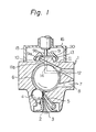
- the invention relates to an open-end spinning unit. More specifically, it relates to an improvement in the conveyance of fiber by a rotor-type open-end spinning unit from the fiber, supply duct thereof to a fiber--collecting groove thereof.
- a sliver 3 supplied through an inlet 2 of the unit 1 is guided to a combing roller 6 by a feed roller 4 and a presser 5, by which the sliver 3 is pressed onto the feed roller 4.
- the sliver 3 is opened into individual fibers by the combing roller 6, and, at the same time, foreign matter 7 such as leaves and trash are expelled through an outlet 8.
- the opened fibers are transported to a spinning chamber 10 of a rotor 9 through a fiber supply duct 11 by an airstream created by a subatmospheric pressure in the chamber 10.
- the fibers thus transported into the chamber 10 reach an inner wall 9a of the rotor 9 and are maintained thereon by a centrifugal force imparted thereto by the rotor 9. Then the fibers slide toward a fiber-collecting groove 13, in which the fibers are collected in the shape of a ribbon.
- the fiber ribbon is drawn out, through a yarn guide hole 14, of the chamber 10 while it.rotates and thereby is twisted to form a yarn.
- the spinning chamber 10 is defined by an inner space of the rotor 9 in a cup-shape having the inner wall 9a and a bottom wall 9b.
- An open space of the rotor is substantially closed by a closing component 20 formed by part of the frame of the spinning unit 1.
- the component 20 projects into the rotor 9 as a frustum--shaped portion 20a on a side wall of which outlet opening lla of the fiber supply duct 11 is provided.
- exhaustion in the spinning chamber 10 for obtaining a subatmospheric pressure therein.
- One type is forced exhaustion, in which the air in the chamber 10 is sucked out. through a clearance between the closing component 20 and the rotor 9 by a suction means (not shown) connected to an outlet 16 on a housing 15 covering all of the rotor 9.
- the other type is a self-exhaustion, in which the air in the chamber 10 is expelled through a plurality of apertures (not shown) provided radially on the bottom wall 9b of the rotor 9 by a centrifugal force imparted by the rotor 9.
- the fibers transported into the chamber 10 through the fiber supply duct 11 be immediately transferred from an airstream 12 of the duct 11 to a vortex whirling in the vicinity of the inner wall 9a so that they can reach the inner wall 9a as soon as possible.
- some of the fibers often fail to smoothly reach the vortex.
- Such fibers float in a vacant space of the spinning chamber 10 and are finally folded into a fiber bundle which is drawn out through the yarn guide hole 14, resulting in a slubby yarn. Even if the fibers reach the inner wall 9a, they tend to deposit in a disordered state in the fiber-collecting groove 13 and result in a weak yarn.
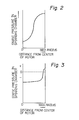
- the static pressure in the chamber 10 in the case of self-exhaustion is low near the center of the rotor 9 and sharply increases toward the inner wall 9a as shown in Fig. 2. Therefore, the fibers transported into the spinning chamber 10 from the fiber supply duct 11 tend to be sucked toward the center of the rotor 9 rather than toward inner wall 9a.
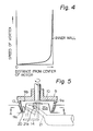
- the vortex generated as a concomitant flow of the rotor 9 in high-speed rotation is effective only a short distance from the inner wall 9a because the velocity thereof sharply decreases as the distance from the inner wall 9a increases, as is shown in Fig. 4.
- the fibers transported into the spinning chamber 10 through the fiber supuly duct 11 are halted midway between the opening lla and the inner wall 9a, resulting in a plurality of floating fibers or bent fibers among the transported fibers.
- These floating or bent fibers cannot be restored to their original straight state even if they are subjected to the stretching action of the vortex prior to their arrival at the inner wall 9a. Therefore, the resultant yarn is both weak in strength and poor in appearance.
- an open-end spinning unit provided with a spinning rotor open on one side and having a bottom wall and an inner wall, the open side being covered with a closing element containing a fiber supply duct having an outlet opening in the closing element, in which at least one suction opening is disposed downstream, relative to the rotation of the rotor, of the outlet opening of the fiber supply duct, whereby an airstream directed in the same direction as the rotation of the rotor is generated from the outlet opening to the suction opening.
- a fiber supply duct 11 similar to a conventional fiber supply duct, is provided in a side wall of a frustum-shaped portion 20a of a closing element 20 in such a manner that the direction of the duct 11 at an outlet opening lla deviates from the radial direction of the rotor 9 so as to point in the rotational direction of the rotor 9. Due to this structure, a first airstream introduced into the spinning chamber 10 from the opening lla can accelerate a concomitant vortex generated inside the rotor 9 by the high-speed rotation thereof.
- the fibers transported into the spinning chamber 10 should be transferred immediately from the airstream from the duct 11 to the concomitant vortex without deceleration of the speed thereof.
- it is very difficult to realize such an ideal state because the fibers tend to be bent due to divergency and deceralation of the first airstream conveying them into the spinning chamber 10, caused by the pressure distribution and the velocity distribution therein.
- the inventive spinning unit is provided with an opening 21a of a suction duct 21 connected to a suction source (not shown), on the side wall of the projected portion 20a of the closing element 20.
- the opening 21a is disposed downstream, in relation to the rotational direction of the rotor 9, of the opening lla of the duct 11. Due to this structure, a second vortex is forcibly generated from the opening lla to the opening 21a in the chamber 10. Since the flowing direction of the second vortex is the same as that of the concomitant vortex, it is gradually accelerated by the concomitant vortex and smoothly joins thereto.
- the fibers transported into the chamber 10 by the first airstream are transferred to the second vortex, in which the fibers are subjected to a circumferential force caused by the acceleration of the second vortex and are stretched along the longitudinal direction thereof. Since a centrifugal force which makes the fibers flow radially outward exerts on the fibers at the same time, the fibers are forced to obliquely cross a space of the spinning chamber between the opening lla and the inner wall 9a, and, thereby, are smoothly transferred to an area of the concomitant, vortex without abrupt decelaration of the the velocity of the fibers. Thus, the fibers can be deposited on the inner wall 9a while maintaining a straight state, and thereby a good mechanical strength is imparted to the resultant yarn.
- the opening 21a of the suction duct 21, as shown in Fig. 6, preferably inclines to oppose the direction of rotation of the rotor 9 so that the second vortex from the opening lla of the fiber supply duct 11 can be effectively received into the opening 21a.
- the suction opening 21a is provided on the side wall of the projected portion 20a in such a manner that a tangent in the rotational direction of the rotor 9 to an imaginary circle encircling the side wall at the suction opening 21a makes an acute angle a relative to an axis of the opening 21a.
- An angular distance a between the openings lla and 21a is preferably more than 45 degrees around the center axis of the closing element 20 as shown in Fig. 6.
- Figure 7 illustrates a second embodiment of the present invention which has, in addition to the abovesaid.
- suction duct 21 and the opening 21a another suction duct 31 and an opening 31a thereof provided in the side wall of the frustum-shaped portion 20a downstream of the opening 21a. Due to the additional opening 31a, the second vortex is enhanced and transfer of the fibers is smoother.
- FIGS 8 and 9 illustrate a third embodiment of the present invention in which two openings 21'a and 31'a are provided in the top wall, rather than in the side wall as in the second embodiment, of the frustum-shaped portion 20a and are communicated with a suction source (not shown) through suction ducts 21' and 31', respectively.
- the functions of the third embodiment are substantially the same as those of the second embodiment.
- FIG. 10 illustrates a fourth embodiment of the present invention.
- a suction. duct 121 is provided in such a manner that an inlet opening 121a is in the top wall of the frustum-shaped portion 20a and an outlet opening 121b opens into the interior of a housing 15 covering the rotor 9.
- a suction flow is generated in the duct 121 by means of a suction source (not shown) utilized for forced exhaustion of the spinning chamber 10 ' through an outlet 16 of the housing 15.
- the suction force of the duct 121 may be controlled by adjusting the proportion of air sucked out through a clearance between the portion 20a and the inner wall 9a of the rotor 9 to the total amount of sucked-out air.
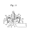
- the present invention is applicable to a self--exhaustion type of spinning unit as shown in Fig. 11, in which spinning unit apertures 18 are provided in the bottom wall 9b for discharging air in the chamber 10.
- the present invention is effective on a combination type of spinning unit (not shown) in which both of a self-exhaustion and a forced-exhaustion are adopted.
- the total cross-sectional areas of the suction openings are preferably larger than the cross-sectional area of the outlet opening of the fiber supply duct.
- the degree of vacuum in the spinning chamber is preferably within a range of from -500 mm to -1,000 mm Aq. This value corresponds to a volume of exhausted air of from 2 l/sec. to 5 Z/sec. when applied to a practical spinning unit. Further, more than three suction openings may be provided if necessary, and any desired shape thereof may be selected.
- fibers transported into a spinning chamber of a rotor can be smoothly deposited on an inner wall of the rotor without being bent due to the influence of a second vortex generated by a newly provided suction opening or openings downstream of an opening of a fiber supply duct.
- the provision of the suction opening or openings also decreases the number of floating fibers which are not transferred to a concomitant vortex and which can possibly be irregularly twisted into a fiber bundle drawn out from the spinning chamber. As a result, the strength and the evenness of the resultant yarn is greatly improved.
Abstract
Description
- The invention relates to an open-end spinning unit. More specifically, it relates to an improvement in the conveyance of fiber by a rotor-type open-end spinning unit from the fiber, supply duct thereof to a fiber--collecting groove thereof.
- The drawbacks of the prior art are explained below with reference to Figs. 1 to 4.
- In the conventional rotor-type open-end spinning unit shown in Fig. 1, a
sliver 3 supplied through aninlet 2 of theunit 1 is guided to a combing roller 6 by afeed roller 4 and apresser 5, by which thesliver 3 is pressed onto thefeed roller 4. Then thesliver 3 is opened into individual fibers by the combing roller 6, and, at the same time, foreign matter 7 such as leaves and trash are expelled through an outlet 8. Thereafter, the opened fibers are transported to aspinning chamber 10 of arotor 9 through afiber supply duct 11 by an airstream created by a subatmospheric pressure in thechamber 10. The fibers thus transported into thechamber 10 reach aninner wall 9a of therotor 9 and are maintained thereon by a centrifugal force imparted thereto by therotor 9. Then the fibers slide toward a fiber-collectinggroove 13, in which the fibers are collected in the shape of a ribbon. The fiber ribbon is drawn out, through ayarn guide hole 14, of thechamber 10 while it.rotates and thereby is twisted to form a yarn. - The
spinning chamber 10 is defined by an inner space of therotor 9 in a cup-shape having theinner wall 9a and abottom wall 9b. An open space of the rotor is substantially closed by aclosing component 20 formed by part of the frame of thespinning unit 1. Thecomponent 20 projects into therotor 9 as a frustum--shapedportion 20a on a side wall of which outlet opening lla of thefiber supply duct 11 is provided. - There are two types of exhaustion in the
spinning chamber 10 for obtaining a subatmospheric pressure therein. One type is forced exhaustion, in which the air in thechamber 10 is sucked out. through a clearance between theclosing component 20 and therotor 9 by a suction means (not shown) connected to anoutlet 16 on ahousing 15 covering all of therotor 9. The other type is a self-exhaustion, in which the air in thechamber 10 is expelled through a plurality of apertures (not shown) provided radially on thebottom wall 9b of therotor 9 by a centrifugal force imparted by therotor 9. It is desirable in both types of exhaustion that the fibers transported into thechamber 10 through thefiber supply duct 11 be immediately transferred from anairstream 12 of theduct 11 to a vortex whirling in the vicinity of theinner wall 9a so that they can reach theinner wall 9a as soon as possible. In the conventional spinning unit, however, some of the fibers often fail to smoothly reach the vortex. Such fibers float in a vacant space of thespinning chamber 10 and are finally folded into a fiber bundle which is drawn out through theyarn guide hole 14, resulting in a slubby yarn. Even if the fibers reach theinner wall 9a, they tend to deposit in a disordered state in the fiber-collectinggroove 13 and result in a weak yarn. - The above-mentioned problems are due to the pressure distribution and velocity distribution of the vortex in the
spinning chamber 10. - According to an investigation made by the present inventors, the static pressure in the
chamber 10 in the case of self-exhaustion is low near the center of therotor 9 and sharply increases toward theinner wall 9a as shown in Fig. 2. Therefore, the fibers transported into thespinning chamber 10 from thefiber supply duct 11 tend to be sucked toward the center of therotor 9 rather than towardinner wall 9a. - This tendency also exists in the
spinning chamber 10 in the case of forced exhaustion. As is shown in Fig. 3, though the pressure distribution in the case of forced exhaustion is considerable equalized compared to that in the case of self-exhaustion, the highest pressure point is in the vicinity of theinner wall 9a. - In addition to the abovesaid pressure distribution, the vortex generated as a concomitant flow of the
rotor 9 in high-speed rotation is effective only a short distance from theinner wall 9a because the velocity thereof sharply decreases as the distance from theinner wall 9a increases, as is shown in Fig. 4. Thus, the fibers transported into thespinning chamber 10 through thefiber supuly duct 11 are halted midway between the opening lla and theinner wall 9a, resulting in a plurality of floating fibers or bent fibers among the transported fibers. These floating or bent fibers cannot be restored to their original straight state even if they are subjected to the stretching action of the vortex prior to their arrival at theinner wall 9a. Therefore, the resultant yarn is both weak in strength and poor in appearance. - It is an object of the present invention to eliminate the aforesaid drawbacks in the conventional spinning unit.
- It is another object of the present invention to provide an open-end spinning unit in which fibers transported into a spinning chamber through a fiber supply duct can immediately reach an inner wall of a rotor without moving about within the spinning chamber, thereby producing a good quality yarn.
- The abovesaid objects can be achieved by an open-end spinning unit provided with a spinning rotor open on one side and having a bottom wall and an inner wall, the open side being covered with a closing element containing a fiber supply duct having an outlet opening in the closing element, in which at least one suction opening is disposed downstream, relative to the rotation of the rotor, of the outlet opening of the fiber supply duct, whereby an airstream directed in the same direction as the rotation of the rotor is generated from the outlet opening to the suction opening.
- The present invention is explained in detail with reference to the accompanying drawings, wherein:
- Fig. 1 is a sectional side view of a conventional open-end, forced-exhaustion type of spinning unit;
- Figs. 2 and 3 are graphs showing the static pressure distribution in a self-exhaustion type of spinning chamber and in a forced-exhaustion type of spinning chamber, respectively;
- Fig. 4 is a graph showing the velocity distribution of a vortex in a forced-exhaustion type of spinning chamber;
- Fig. 5 is a fragmental sectional side view of a spinning unit according to a first embodiment of the present invention;
- Fig. 6 is a sectional plan view of the first embodiment along the line A-A in Fig. 5;
- Fig. 7 is a sectional plan view of a spinning unit according to a second embodiment of the present invention;
- Figs. 8 and 9 are a sectional side view and a sectional plan view, respectively, of a spinning unit according to a third embodiment of the present invention;
- Fig. 10 is a sectional side view of a spinning unit according to a fourth embodiment of the present invention; and
- Fig. 11 is a sectional side view of a spinning unit according to a fifth embodiment of the present invention.
- A first embodiment of the present invention is illustrated in Figs. 5 and 6. In the figures, a
fiber supply duct 11, similar to a conventional fiber supply duct, is provided in a side wall of a frustum-shaped portion 20a of aclosing element 20 in such a manner that the direction of theduct 11 at an outlet opening lla deviates from the radial direction of therotor 9 so as to point in the rotational direction of therotor 9. Due to this structure, a first airstream introduced into thespinning chamber 10 from the opening lla can accelerate a concomitant vortex generated inside therotor 9 by the high-speed rotation thereof. The fibers transported into thespinning chamber 10 should be transferred immediately from the airstream from theduct 11 to the concomitant vortex without deceleration of the speed thereof. However, as was mentioned before, it is very difficult to realize such an ideal state because the fibers tend to be bent due to divergency and deceralation of the first airstream conveying them into thespinning chamber 10, caused by the pressure distribution and the velocity distribution therein. - To improve this point, the inventive spinning unit is provided with an opening 21a of a
suction duct 21 connected to a suction source (not shown), on the side wall of the projectedportion 20a of theclosing element 20. The opening 21a is disposed downstream, in relation to the rotational direction of therotor 9, of the opening lla of theduct 11. Due to this structure, a second vortex is forcibly generated from the opening lla to the opening 21a in thechamber 10. Since the flowing direction of the second vortex is the same as that of the concomitant vortex, it is gradually accelerated by the concomitant vortex and smoothly joins thereto. - The fibers transported into the
chamber 10 by the first airstream are transferred to the second vortex, in which the fibers are subjected to a circumferential force caused by the acceleration of the second vortex and are stretched along the longitudinal direction thereof. Since a centrifugal force which makes the fibers flow radially outward exerts on the fibers at the same time, the fibers are forced to obliquely cross a space of the spinning chamber between the opening lla and theinner wall 9a, and, thereby, are smoothly transferred to an area of the concomitant, vortex without abrupt decelaration of the the velocity of the fibers. Thus, the fibers can be deposited on theinner wall 9a while maintaining a straight state, and thereby a good mechanical strength is imparted to the resultant yarn. - The opening 21a of the
suction duct 21, as shown in Fig. 6, preferably inclines to oppose the direction of rotation of therotor 9 so that the second vortex from the opening lla of thefiber supply duct 11 can be effectively received into the opening 21a. - That is, the suction opening 21a is provided on the side wall of the projected
portion 20a in such a manner that a tangent in the rotational direction of therotor 9 to an imaginary circle encircling the side wall at the suction opening 21a makes an acute angle a relative to an axis of the opening 21a. - An angular distance a between the openings lla and 21a is preferably more than 45 degrees around the center axis of the
closing element 20 as shown in Fig. 6. - Figure 7 illustrates a second embodiment of the present invention which has, in addition to the abovesaid.
suction duct 21 and the opening 21a, anothersuction duct 31 and an opening 31a thereof provided in the side wall of the frustum-shaped portion 20a downstream of the opening 21a. Due to theadditional opening 31a, the second vortex is enhanced and transfer of the fibers is smoother. - Figures 8 and 9 illustrate a third embodiment of the present invention in which two openings 21'a and 31'a are provided in the top wall, rather than in the side wall as in the second embodiment, of the frustum-shaped
portion 20a and are communicated with a suction source (not shown) through suction ducts 21' and 31', respectively. The functions of the third embodiment are substantially the same as those of the second embodiment. - Figure 10 illustrates a fourth embodiment of the present invention. In this embodiment, a suction.
duct 121 is provided in such a manner that an inlet opening 121a is in the top wall of the frustum-shapedportion 20a and anoutlet opening 121b opens into the interior of ahousing 15 covering therotor 9. A suction flow is generated in theduct 121 by means of a suction source (not shown) utilized for forced exhaustion of the spinningchamber 10 'through anoutlet 16 of thehousing 15. In this case, the suction force of theduct 121 may be controlled by adjusting the proportion of air sucked out through a clearance between theportion 20a and theinner wall 9a of therotor 9 to the total amount of sucked-out air. - The present invention is applicable to a self--exhaustion type of spinning unit as shown in Fig. 11, in which
spinning unit apertures 18 are provided in thebottom wall 9b for discharging air in thechamber 10. - Further, the present invention is effective on a combination type of spinning unit (not shown) in which both of a self-exhaustion and a forced-exhaustion are adopted.
- The total cross-sectional areas of the suction openings are preferably larger than the cross-sectional area of the outlet opening of the fiber supply duct. The degree of vacuum in the spinning chamber is preferably within a range of from -500 mm to -1,000 mm Aq. This value corresponds to a volume of exhausted air of from 2 ℓ/sec. to 5 Z/sec. when applied to a practical spinning unit. Further, more than three suction openings may be provided if necessary, and any desired shape thereof may be selected.
- As was described above, according to the present invention, fibers transported into a spinning chamber of a rotor can be smoothly deposited on an inner wall of the rotor without being bent due to the influence of a second vortex generated by a newly provided suction opening or openings downstream of an opening of a fiber supply duct. The provision of the suction opening or openings also decreases the number of floating fibers which are not transferred to a concomitant vortex and which can possibly be irregularly twisted into a fiber bundle drawn out from the spinning chamber. As a result, the strength and the evenness of the resultant yarn is greatly improved.
Claims (9)
Applications Claiming Priority (2)
| Application Number | Priority Date | Filing Date | Title |
|---|---|---|---|
| JP57105471A JPS591732A (en) | 1982-06-21 | 1982-06-21 | Open end spinning machine |
| JP105471/82 | 1982-06-21 |
Publications (2)
| Publication Number | Publication Date |
|---|---|
| EP0097511A2 true EP0097511A2 (en) | 1984-01-04 |
| EP0097511A3 EP0097511A3 (en) | 1986-08-06 |
Family
ID=14408502
Family Applications (1)
| Application Number | Title | Priority Date | Filing Date |
|---|---|---|---|
| EP83303531A Withdrawn EP0097511A3 (en) | 1982-06-21 | 1983-06-20 | Open-end spinning unit |
Country Status (4)
| Country | Link |
|---|---|
| US (1) | US4510745A (en) |
| EP (1) | EP0097511A3 (en) |
| JP (1) | JPS591732A (en) |
| KR (1) | KR850000722B1 (en) |
Cited By (2)
| Publication number | Priority date | Publication date | Assignee | Title |
|---|---|---|---|---|
| DE4306272A1 (en) * | 1993-03-01 | 1994-09-08 | Rieter Ingolstadt Spinnerei | Process and apparatus for producing a thread by means of an open-end spinning apparatus |
| US7209900B2 (en) * | 1999-08-27 | 2007-04-24 | Charles Eric Hunter | Music distribution systems |
Families Citing this family (8)
| Publication number | Priority date | Publication date | Assignee | Title |
|---|---|---|---|---|
| CS258325B1 (en) * | 1986-06-27 | 1988-08-16 | Frantisek Jaros | Spinning frame |
| DE3917991A1 (en) * | 1989-06-02 | 1990-12-06 | Fritz Stahlecker | DEVICE FOR OE ROTOR SPINNING |
| US5359846A (en) * | 1991-07-29 | 1994-11-01 | Kabushiki Kaisha Toyoda Jidoshokki Seisakusho | Spinning apparatus of rotor type open-end spinning unit and rotor driving method |
| DE4131666C2 (en) * | 1991-09-23 | 1996-02-29 | Rieter Ingolstadt Spinnerei | Method and device for cleaning an open-end spinning rotor |
| SK386291A3 (en) * | 1991-12-18 | 1995-06-07 | Vyzk Ustav Bavlnarsky A S | Rotary spinning device |
| JP3794136B2 (en) * | 1997-11-21 | 2006-07-05 | 株式会社豊田自動織機 | Fiber transport device for rotor type open-end spinning machine |
| CN102704062A (en) * | 2012-06-21 | 2012-10-03 | 河北金纺机械制造有限公司 | Air extraction revolving cup spinning machine capable of producing low-twist bulky yarns |
| CN104264296B (en) * | 2014-08-22 | 2016-08-17 | 东华大学 | A kind of revolving cup |
Citations (2)
| Publication number | Priority date | Publication date | Assignee | Title |
|---|---|---|---|---|
| FR1582426A (en) * | 1967-09-27 | 1969-09-26 | ||
| DE2737702A1 (en) * | 1976-09-02 | 1978-03-16 | Vyzk Ustav Bavlnarsky | METHOD AND DEVICE FOR PNEUMATICALLY REMOVING FIBER TAPES |
Family Cites Families (2)
| Publication number | Priority date | Publication date | Assignee | Title |
|---|---|---|---|---|
| DE2155171B2 (en) * | 1971-11-05 | 1979-11-22 | Ltg Lufttechnische Gmbh, 7000 Stuttgart | OE rotor spinning machine |
| GB1419498A (en) * | 1972-02-23 | 1975-12-31 | Platt Saco Lowell Ltd | Spinning of textile fibres |
-
1982
- 1982-06-21 JP JP57105471A patent/JPS591732A/en active Granted
-
1983
- 1983-06-18 KR KR1019830002732A patent/KR850000722B1/en active
- 1983-06-20 EP EP83303531A patent/EP0097511A3/en not_active Withdrawn
- 1983-06-21 US US06/506,327 patent/US4510745A/en not_active Expired - Fee Related
Patent Citations (2)
| Publication number | Priority date | Publication date | Assignee | Title |
|---|---|---|---|---|
| FR1582426A (en) * | 1967-09-27 | 1969-09-26 | ||
| DE2737702A1 (en) * | 1976-09-02 | 1978-03-16 | Vyzk Ustav Bavlnarsky | METHOD AND DEVICE FOR PNEUMATICALLY REMOVING FIBER TAPES |
Cited By (3)
| Publication number | Priority date | Publication date | Assignee | Title |
|---|---|---|---|---|
| DE4306272A1 (en) * | 1993-03-01 | 1994-09-08 | Rieter Ingolstadt Spinnerei | Process and apparatus for producing a thread by means of an open-end spinning apparatus |
| US7209900B2 (en) * | 1999-08-27 | 2007-04-24 | Charles Eric Hunter | Music distribution systems |
| US9659285B2 (en) * | 1999-08-27 | 2017-05-23 | Zarbaña Digital Fund Llc | Music distribution systems |
Also Published As
| Publication number | Publication date |
|---|---|
| EP0097511A3 (en) | 1986-08-06 |
| JPS591732A (en) | 1984-01-07 |
| JPS64488B2 (en) | 1989-01-06 |
| KR850000722B1 (en) | 1985-05-23 |
| KR840005178A (en) | 1984-11-05 |
| US4510745A (en) | 1985-04-16 |
Similar Documents
| Publication | Publication Date | Title |
|---|---|---|
| US4315398A (en) | Open-end spinning apparatus | |
| US4510745A (en) | Open-end spinning unit | |
| US3538698A (en) | Break-spinning apparatus | |
| US4773209A (en) | Method of and apparatus for producing a friction spun yarn | |
| US4058964A (en) | Open-end rotor for a spinning machine | |
| US5890356A (en) | Open-end fiber veil spinning apparatus and method | |
| GB2054671A (en) | Open-end spinning apparatus | |
| EP0071453B1 (en) | Open-end spinning unit | |
| US4606187A (en) | Fiber feeding air flow arrangement for open-end friction spinning | |
| US3844100A (en) | Apparatus for the open-end spinning of textile yarns | |
| US4077195A (en) | Open-end spinning aggregate | |
| US5488822A (en) | Curved fiber guide channel for an open-end spinning apparatus | |
| CS258325B1 (en) | Spinning frame | |
| US4479348A (en) | Apparatus for spinning fasciated yarn | |
| CA1040021A (en) | Vacuum system for open end spinning machine | |
| US4314440A (en) | Dust removing mechanism in open-end spinning frame | |
| CZ286393A3 (en) | Process and apparatus for open-end spinning | |
| KR850000916B1 (en) | Learer apparatus in open end spinning | |
| CS232869B1 (en) | Method of yarn spinning from staple fibres in air swirl and equipment for application of this method | |
| US4030280A (en) | Fiber blending, subdividing, and distributing system | |
| US4640089A (en) | Method and device for spinning a yarn in accordance with the open end-friction spinning principle | |
| US5175991A (en) | Arrangement for pneumatic false-twist spinning | |
| US5367868A (en) | Process and device for open-end spinning | |
| US5687558A (en) | Fiber supply arrangement for open-end rotor spinning | |
| GB2178451A (en) | Open-end spinning |
Legal Events
| Date | Code | Title | Description |
|---|---|---|---|
| PUAI | Public reference made under article 153(3) epc to a published international application that has entered the european phase |
Free format text: ORIGINAL CODE: 0009012 |
|
| AK | Designated contracting states |
Designated state(s): CH DE GB LI |
|
| PUAL | Search report despatched |
Free format text: ORIGINAL CODE: 0009013 |
|
| AK | Designated contracting states |
Kind code of ref document: A3 Designated state(s): CH DE GB LI |
|
| STAA | Information on the status of an ep patent application or granted ep patent |
Free format text: STATUS: THE APPLICATION IS DEEMED TO BE WITHDRAWN |
|
| 18D | Application deemed to be withdrawn |
Effective date: 19870515 |
|
| RIN1 | Information on inventor provided before grant (corrected) |
Inventor name: KANEKO, MASASHI Inventor name: KAWABATA, SUSUMU Inventor name: SHIBUYA, MASANOBU Inventor name: INOUE, TETSUZO Inventor name: MIYAMOTO, NORIAKI |