EP0097136A2 - Rock drilling apparatus - Google Patents
Rock drilling apparatus Download PDFInfo
- Publication number
- EP0097136A2 EP0097136A2 EP83850155A EP83850155A EP0097136A2 EP 0097136 A2 EP0097136 A2 EP 0097136A2 EP 83850155 A EP83850155 A EP 83850155A EP 83850155 A EP83850155 A EP 83850155A EP 0097136 A2 EP0097136 A2 EP 0097136A2
- Authority
- EP
- European Patent Office
- Prior art keywords
- tool
- drilling
- tube
- outer tube
- rock
- Prior art date
- Legal status (The legal status is an assumption and is not a legal conclusion. Google has not performed a legal analysis and makes no representation as to the accuracy of the status listed.)
- Granted
Links
- 238000005553 drilling Methods 0.000 title claims abstract description 32
- 239000011435 rock Substances 0.000 title claims abstract description 24
- 239000012530 fluid Substances 0.000 claims description 3
- 230000008878 coupling Effects 0.000 claims description 2
- 238000010168 coupling process Methods 0.000 claims description 2
- 238000005859 coupling reaction Methods 0.000 claims description 2
- 238000011010 flushing procedure Methods 0.000 claims description 2
- 230000000063 preceeding effect Effects 0.000 claims 1
- 239000002184 metal Substances 0.000 abstract 1
- 238000005520 cutting process Methods 0.000 description 2
- 238000010586 diagram Methods 0.000 description 2
- 239000007788 liquid Substances 0.000 description 2
- 238000000034 method Methods 0.000 description 1
- 230000007935 neutral effect Effects 0.000 description 1
- 230000035515 penetration Effects 0.000 description 1
- 238000010008 shearing Methods 0.000 description 1
- XLYOFNOQVPJJNP-UHFFFAOYSA-N water Substances O XLYOFNOQVPJJNP-UHFFFAOYSA-N 0.000 description 1
Images


Classifications
-
- E—FIXED CONSTRUCTIONS
- E21—EARTH DRILLING; MINING
- E21B—EARTH DRILLING, e.g. DEEP DRILLING; OBTAINING OIL, GAS, WATER, SOLUBLE OR MELTABLE MATERIALS OR A SLURRY OF MINERALS FROM WELLS
- E21B44/00—Automatic control systems specially adapted for drilling operations, i.e. self-operating systems which function to carry out or modify a drilling operation without intervention of a human operator, e.g. computer-controlled drilling systems; Systems specially adapted for monitoring a plurality of drilling variables or conditions
- E21B44/02—Automatic control of the tool feed
-
- E—FIXED CONSTRUCTIONS
- E21—EARTH DRILLING; MINING
- E21B—EARTH DRILLING, e.g. DEEP DRILLING; OBTAINING OIL, GAS, WATER, SOLUBLE OR MELTABLE MATERIALS OR A SLURRY OF MINERALS FROM WELLS
- E21B7/00—Special methods or apparatus for drilling
- E21B7/18—Drilling by liquid or gas jets, with or without entrained pellets
Definitions
- This invention relates to a rock drilling apparatus for drilling holes by means of high pressure hydraulic jet including a rock drill body, a drilling tool attached to said rock drill body, and a feeding device with a motor for feeding said body and tool to and fro the working face, said rock drilling tool incorporating an inner rotating rod with a high pressure nozzle body at the nose thereof and an outer non-rotating tube surrounding said inner rod, said rock drill body being provided with a means for supplying high pressure hydraulics to said nozzle and a rotating mechanism for rotating said inner tube.
- Drilling apparatus of the kind described above which have a power feed device for example a feed leg.
- the feed device brings a certain thrust to the drilling tool which thrust is chosen by experience of the rock quality in order to continuously advance the tool into the drill hole. If the advancing rate is chosen too high the expensive drill nozzle will abut against the working face of the drill hole and get damaged. On the other hand if the tool is advanced too slow the drilling capacity will be unsufficiently profiled. But also when the tool is fed with a speed chosen low enough for being on the safe side the nozzle might hit harder fractures in the rock and get stopped until the operator observes the stoppage. But before that the nozzle might be damaged or an unwanted chamber cut out in the rock.
- An object of the present invention is therefore to provide a jet drilling apparatus which avoids the above drawbacks of the known apparatus and which calibrates the size of the drill hole and maximizes the penetration speed.
- the shown embodiment includes a rock drill body 11 with a jet drilling tool 12 connected thereto.
- the drill body 11 is mounted on a cradle 13 which is displaceable along a feed beam 14 by means of a feeding device 15.
- Said feed beam 14 is attached to positioning means , not shown, including a swinging arm carried by a movable chassis in a manner previously known from conventional rock drilling.
- the feeding device 15 comprises a hydraulic cylinder and piston arrangement of which only a part of the piston 16 is shown. There is also possible to use other suitable feeds including a hydraulic motor.
- the cradle 13 is carried on rolls 17 which run on guide bars 18 in the feed beam 14.
- the drill body 11 contains a rotating shaft 19 journalled on bearings 20 and comprising a longitudinal bore 21 for leading high-pressure hydraulic fluid to the drilling tool 12.
- the fluid is led into the drill body from an external high pressure pump, not shown, by an inlet 22 and a passage 23 into which one end 24 of the shaft 19 is sealingly inserted .
- a hydraulic motor 25 is held by a stand 26 mounted to the cradle 13 and is arranged for rotating said shaft 19 by means of a timing belt 27 laid over belt wheels 28, 29 on the motor shaft 30 and the rotating shaft 19 respectively.
- the jet drilling tool 12 comprises an inner rotating tube 40 with a high pressure nozzle body 41 at the nose thereof and an outer non-rotating tube 42 surrounding said inner tube.
- the rear end of the inner tube 40 is provided with a threaded sleeve 43 for connection with the front end 44 of the rotating shaft 19.
- a projecting part 45 of the inner tube 40 is inserted into the bore 21 for making a suitable connection for the distribution of high pressure liquid from the bore 21 into the tube 40.
- the liquid is led through the interior 46 of the tube 40 to the nozzle body 41 which contains two nozzles 47, 48 (Fig 5) at the front end for forming the hydraulic jets 49, 50 which brake the rock at the working face 51.
- the rear end of the outer tube 42 comprises a tube head 51 welded thereto.
- Said tube head 51 is provided with a recess 52 fitting into a hole 53 of a drill holder 54 which is mounted to the cradle 13.
- the head 51 is demountably secured to said holder 54 by a ring 55 threaded on said recess 52.
- other suitable coupling means can be used for non-rotatably connecting the outer tube 42 to the drill holder 54.
- the drill tool 12 is guided by a forward drill support 56 attached to the feed beam 14 and a middle support 57 deplaceable along the beam 14.
- the tube head is provided with an inlet 58 and an annular chamber 59 for leading low pressure flushing medium preferably water into an annular space 60 between the tubes 40,42 and further around the nozzle body 41 out to the nose of the tool.
- the front part of the outer tube 42 comprises a collar 61 for calibration of the drill hole size during drilling operation.
- the collar 61 is provided with spiral grooves 62 on the outside to allow the drill cuttings to flow backwards and still maintain circular calibration. The spiral shape will also make it easier to eliminate minor projecting rock parts in the hole by shearing them off when the non-rotating collar advances.
- the front end of the collar 61 has a V-cut edge 63 for allowing the jet 50 to flow towards the periphery of the hole.
- the feeding device 15 comprises as mentioned a hydraulic motor 16 which might be a rotary motor or a cylinder and piston motor.
- the hydraulic system for driving said motor appears from Fig 5 and includes in addition to said motor 16 a pump 70 with a driving motor 71, a directional control valve 72 and a pressure operated switch 73 of any known suitable kind for example Telemecanique XM2 - JM160 or Rexroth HED 40 AIX/50.
- a sequence valve 74 with variable pressure is coupled in parallel with the pump 70 and a combination 75 of throttle valve and non-return valve with variable throttling is arranged on each side of the feed motor 16.
- the feeding direction and the feeding speed is operated by the control valve 72-which in its advancing position according to the right symbol feeds the tool 12 forwards towards the working face and in its retracting position according to the left symbol retracts the tool.
- the applied hydraulic pressure is sensed by the switch 73 and if the pressure rises over a preset value the switch changes over and the control valve 72 is electrically switched to the left position whereby the tool is retracted.
- the electric control of the valve 72 is shown more in detail in Fig 6.
- the valve 72 is electromagnetically operated by a first 80 and a second 81 coil which are selectively activated by a manually operat- ;ed main switch 82 connected to a source of current, not shown.
- the switch 82 When advancing the drilling tool 12, the switch 82 is set in the position A whereby a terminal 90 and a terminal 94 of an adjustable time relay 83 are set under tension.
- said relay can be of any known suitable kind for example Nordela RS 121 or Sprecher and Schuh RZEW2-03 with delaying time intervals of about 0.05 - 1 second.
- a terminal 92 connected to the first coil 80 is also set under tension as seen from Fig 7 which brings the valve 72 to take its advancing position.
- the sensing switch 73 closes which changes the contact between terminal 94 and 92 to a contact between terminal 94 and 93 for a preset time interval. Now the first coil is disconnected and instead the second coil is set under tension which brings the valve 72 to take its retracting position. When said time interval has expired the sensing switch 73 opens again and the control valve 72 returns to its advancing position.
- the main switch 82 has also a position 0 and a position R for placing the control valve 72 in its neutral and retracting position respectively.
- the time relay is disconnectable by connecting terminal 91 to earth with a manual control 84.
- the feeding speed is set in relation to the rock quality in order to get a drill hole somewhat wider than the size of the collar 61. Since the rock seldom is of homogenous quality the set speed can only be a rough approximation preferably determined so that the softest expected rock parts will be drilled with a hole size not too much wider than the collar.
- the drilling tool reaches harder rock parts eg. a hard inclusion the collar abuts against the rock face and the hydraulic pressure in the feeding device starts to rise. Minor obstructions will be cut off by the spiral-groove arrangement as previously described but bigger ones will cause the pressure to rise over the pre-set limit of the sensing device 73 and the feeding device starts to retract the drilling tool as also previously described.
- the time interval for said retractive motion is adjustable within 0.05 - 1 second for adapting to different drilling conditions.
- delaying time interval there is also possible to determine the action of the control valve 72 as function of the retract distance as picked , for example, directly on the hydraulic motor.
- a further possibility is to combine parameters of time and distance.
- Another alternative is to dynamically adjust the time intervals or the retracted distances by a micro-processor 85, schematically shown in Fig 6, working as a tuning element minimizing some combination of the retraction cycles and the sum of the retracted distances so as to give optimum advance rate.
- the system should ideally work so that the drilling tool advances without reverse motion, since all retraction cuts back the net advance rate, but as fast as possible.
Abstract
Description
- This invention relates to a rock drilling apparatus for drilling holes by means of high pressure hydraulic jet including a rock drill body, a drilling tool attached to said rock drill body, and a feeding device with a motor for feeding said body and tool to and fro the working face, said rock drilling tool incorporating an inner rotating rod with a high pressure nozzle body at the nose thereof and an outer non-rotating tube surrounding said inner rod, said rock drill body being provided with a means for supplying high pressure hydraulics to said nozzle and a rotating mechanism for rotating said inner tube.
- Drilling apparatus of the kind described above are known which have a power feed device for example a feed leg. The feed device brings a certain thrust to the drilling tool which thrust is chosen by experience of the rock quality in order to continuously advance the tool into the drill hole. If the advancing rate is chosen too high the expensive drill nozzle will abut against the working face of the drill hole and get damaged. On the other hand if the tool is advanced too slow the drilling capacity will be unsufficiently profiled. But also when the tool is fed with a speed chosen low enough for being on the safe side the nozzle might hit harder fractures in the rock and get stopped until the operator observes the stoppage. But before that the nozzle might be damaged or an unwanted chamber cut out in the rock.
- An object of the present invention is therefore to provide a jet drilling apparatus which avoids the above drawbacks of the known apparatus and which calibrates the size of the drill hole and maximizes the penetration speed.
- This object and others are achieved by providing a jet drilling apparatus according to the accompanying claims.
- The invention will now be described more in detail referring to the accompanying drawings, in which:
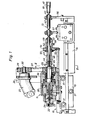
- Fig 1 is a side view partly in section of a drilling apparatus according to the invention.
- Fig 2 is a cross section taken along the line 2-2 in Fig 1 .
- Fig 3 is a side view of the nose of the drilling tool partly in section and in an enlarged scale shown in a drill hole.
- Fig 4 is a front side view seen from the -line 4-4 in Fig 3.
- Fig 5 is a schematic diagram of a hydraulic circuit including the feed motor.
- Fig 6 is a schematic diagram of an electric circuit for operating the feed motor.
- Fig 7 is a detail of.the circuit in Fig 6.
- The shown embodiment includes a
rock drill body 11 with a jet drilling tool 12 connected thereto. Thedrill body 11 is mounted on acradle 13 which is displaceable along afeed beam 14 by means of afeeding device 15. Saidfeed beam 14 is attached to positioning means , not shown, including a swinging arm carried by a movable chassis in a manner previously known from conventional rock drilling. Thefeeding device 15 comprises a hydraulic cylinder and piston arrangement of which only a part of thepiston 16 is shown. There is also possible to use other suitable feeds including a hydraulic motor. Thecradle 13 is carried onrolls 17 which run onguide bars 18 in thefeed beam 14. - The
drill body 11 contains a rotatingshaft 19 journalled onbearings 20 and comprising alongitudinal bore 21 for leading high-pressure hydraulic fluid to the drilling tool 12. The fluid is led into the drill body from an external high pressure pump, not shown, by aninlet 22 and apassage 23 into which oneend 24 of theshaft 19 is sealingly inserted . Ahydraulic motor 25 is held by astand 26 mounted to thecradle 13 and is arranged for rotating saidshaft 19 by means of atiming belt 27 laid overbelt wheels motor shaft 30 and the rotatingshaft 19 respectively. - The jet drilling tool 12 comprises an inner rotating
tube 40 with a highpressure nozzle body 41 at the nose thereof and anouter non-rotating tube 42 surrounding said inner tube. The rear end of theinner tube 40 is provided with a threadedsleeve 43 for connection with thefront end 44 of the rotatingshaft 19. A projectingpart 45 of theinner tube 40 is inserted into thebore 21 for making a suitable connection for the distribution of high pressure liquid from thebore 21 into thetube 40. The liquid is led through theinterior 46 of thetube 40 to thenozzle body 41 which contains two nozzles 47, 48 (Fig 5) at the front end for forming thehydraulic jets face 51. The rear end of theouter tube 42 comprises atube head 51 welded thereto. Saidtube head 51 is provided with a recess 52 fitting into ahole 53 of adrill holder 54 which is mounted to thecradle 13. Thehead 51 is demountably secured to saidholder 54 by aring 55 threaded on said recess 52. Also other suitable coupling means can be used for non-rotatably connecting theouter tube 42 to thedrill holder 54. The drill tool 12 is guided by aforward drill support 56 attached to thefeed beam 14 and amiddle support 57 deplaceable along thebeam 14. - The tube head is provided with an
inlet 58 and an annular chamber 59 for leading low pressure flushing medium preferably water into anannular space 60 between thetubes nozzle body 41 out to the nose of the tool. By this arrangement there will be easy to accomplish a sufficient flush flow and a minimum of cuttings will penetrate into thespace 60 between the rotatingnozzle body 41 and thetube 42 which keeps the wear down. The front part of theouter tube 42 comprises acollar 61 for calibration of the drill hole size during drilling operation. Thecollar 61 is provided withspiral grooves 62 on the outside to allow the drill cuttings to flow backwards and still maintain circular calibration. The spiral shape will also make it easier to eliminate minor projecting rock parts in the hole by shearing them off when the non-rotating collar advances. The front end of thecollar 61 has a V-cut edge 63 for allowing thejet 50 to flow towards the periphery of the hole. - The
feeding device 15 comprises as mentioned ahydraulic motor 16 which might be a rotary motor or a cylinder and piston motor. The hydraulic system for driving said motor appears from Fig 5 and includes in addition to said motor 16 apump 70 with a drivingmotor 71, adirectional control valve 72 and a pressure operatedswitch 73 of any known suitable kind for example Telemecanique XM2 - JM160 or Rexroth HED 40 AIX/50. Asequence valve 74 with variable pressure is coupled in parallel with thepump 70 and acombination 75 of throttle valve and non-return valve with variable throttling is arranged on each side of thefeed motor 16. The feeding direction and the feeding speed is operated by the control valve 72-which in its advancing position according to the right symbol feeds the tool 12 forwards towards the working face and in its retracting position according to the left symbol retracts the tool. When the tool is fed forwards the applied hydraulic pressure is sensed by theswitch 73 and if the pressure rises over a preset value the switch changes over and thecontrol valve 72 is electrically switched to the left position whereby the tool is retracted. - The electric control of the
valve 72 is shown more in detail in Fig 6. Thevalve 72 is electromagnetically operated by a first 80 and a second 81 coil which are selectively activated by a manually operat- ;edmain switch 82 connected to a source of current, not shown. When advancing the drilling tool 12, theswitch 82 is set in the position A whereby aterminal 90 and aterminal 94 of anadjustable time relay 83 are set under tension.Said relay can be of any known suitable kind for example Nordela RS 121 or Sprecher and Schuh RZEW2-03 with delaying time intervals of about 0.05 - 1 second. Aterminal 92 connected to thefirst coil 80 is also set under tension as seen from Fig 7 which brings thevalve 72 to take its advancing position. If the hydraulic pressure rises over said preset value thesensing switch 73 closes which changes the contact betweenterminal terminal valve 72 to take its retracting position. When said time interval has expired thesensing switch 73 opens again and thecontrol valve 72 returns to its advancing position. Themain switch 82 has also a position 0 and a position R for placing thecontrol valve 72 in its neutral and retracting position respectively. The time relay is disconnectable by connectingterminal 91 to earth with amanual control 84. - During operation of the drilling apparatus the feeding speed is set in relation to the rock quality in order to get a drill hole somewhat wider than the size of the
collar 61. Since the rock seldom is of homogenous quality the set speed can only be a rough approximation preferably determined so that the softest expected rock parts will be drilled with a hole size not too much wider than the collar. When the drilling tool reaches harder rock parts eg. a hard inclusion the collar abuts against the rock face and the hydraulic pressure in the feeding device starts to rise. Minor obstructions will be cut off by the spiral-groove arrangement as previously described but bigger ones will cause the pressure to rise over the pre-set limit of thesensing device 73 and the feeding device starts to retract the drilling tool as also previously described. The time interval for said retractive motion is adjustable within 0.05 - 1 second for adapting to different drilling conditions. When said time interval has come to an end the tool advances again and if thejets - As an alternative to said delaying time interval there is also possible to determine the action of the
control valve 72 as function of the retract distance as picked , for example, directly on the hydraulic motor. A further possibility is to combine parameters of time and distance. - Another alternative is to dynamically adjust the time intervals or the retracted distances by a micro-processor 85, schematically shown in Fig 6, working as a tuning element minimizing some combination of the retraction cycles and the sum of the retracted distances so as to give optimum advance rate. The system should ideally work so that the drilling tool advances without reverse motion, since all retraction cuts back the net advance rate, but as fast as possible.
- It is to be noted that the invention is not limited to the described embodiment but can be varied in many ways within the scope of the accompanying claims.
Claims (10)
Priority Applications (1)
| Application Number | Priority Date | Filing Date | Title |
|---|---|---|---|
| AT83850155T ATE33874T1 (en) | 1982-06-22 | 1983-06-07 | DEVICE FOR ROCK DRILLING. |
Applications Claiming Priority (2)
| Application Number | Priority Date | Filing Date | Title |
|---|---|---|---|
| SE8203865 | 1982-06-22 | ||
| SE8203865A SE447502B (en) | 1982-06-22 | 1982-06-22 | FEEDING DEVICE AT THE MOUNTAIN DRILL CONDITION FOR DRILLING WITH SCREWS |
Publications (3)
| Publication Number | Publication Date |
|---|---|
| EP0097136A2 true EP0097136A2 (en) | 1983-12-28 |
| EP0097136A3 EP0097136A3 (en) | 1985-09-18 |
| EP0097136B1 EP0097136B1 (en) | 1988-04-27 |
Family
ID=20347143
Family Applications (1)
| Application Number | Title | Priority Date | Filing Date |
|---|---|---|---|
| EP83850155A Expired EP0097136B1 (en) | 1982-06-22 | 1983-06-07 | Rock drilling apparatus |
Country Status (9)
| Country | Link |
|---|---|
| US (1) | US4503918A (en) |
| EP (1) | EP0097136B1 (en) |
| JP (1) | JPS5910693A (en) |
| AT (1) | ATE33874T1 (en) |
| AU (1) | AU551398B2 (en) |
| CA (1) | CA1203227A (en) |
| DE (1) | DE3376442D1 (en) |
| SE (1) | SE447502B (en) |
| ZA (1) | ZA834336B (en) |
Cited By (1)
| Publication number | Priority date | Publication date | Assignee | Title |
|---|---|---|---|---|
| KR101280277B1 (en) * | 2005-08-29 | 2013-07-01 | 다우 코닝 도레이 캄파니 리미티드 | Insulating liquid die-bonding agent and semiconductor device |
Families Citing this family (18)
| Publication number | Priority date | Publication date | Assignee | Title |
|---|---|---|---|---|
| FI67604C (en) * | 1983-06-14 | 1985-04-10 | Tampella Oy Ab | ADJUSTMENT OF MEASURES |
| US4839936A (en) * | 1987-12-03 | 1989-06-20 | Sewer Rodding Equipment Company | Automated sewer cleaning rodding machine |
| FI85614C (en) * | 1989-04-05 | 1992-05-11 | Tampella Oy Ab | BERGBORRNINGSANORDNING. |
| FR2663680B1 (en) * | 1990-06-26 | 1992-09-11 | Eimco Secoma | ANCHORING EFFORT CONTROL DEVICE FOR A DRILLING SLIDE. |
| FR2667110A1 (en) * | 1990-09-20 | 1992-03-27 | Secoma Sa | Device for monitoring the thrust force for a telescopic drilling jar |
| FI943695A (en) * | 1994-08-10 | 1996-02-11 | Valto Ilomaeki | Method for adjusting the drilling rig |
| AUPN703195A0 (en) * | 1995-12-08 | 1996-01-04 | Bhp Australia Coal Pty Ltd | Fluid drilling system |
| US20020043404A1 (en) * | 1997-06-06 | 2002-04-18 | Robert Trueman | Erectable arm assembly for use in boreholes |
| US6216800B1 (en) | 1998-11-24 | 2001-04-17 | J. H. Fletcher & Co., Inc. | In-situ drilling system with dust collection and overload control |
| US6637522B2 (en) | 1998-11-24 | 2003-10-28 | J. H. Fletcher & Co., Inc. | Enhanced computer control of in-situ drilling system |
| SE0003881L (en) * | 2000-10-26 | 2002-03-26 | Atlas Copco Rock Drills Ab | Procedure for rock drilling |
| AUPR886401A0 (en) * | 2001-11-14 | 2001-12-06 | Cmte Development Limited | Fluid drilling head |
| WO2004016900A1 (en) * | 2002-07-24 | 2004-02-26 | Tiefenbach Bergbautechnik Gmbh | Mobile working tool with a tool head |
| AU2002952176A0 (en) | 2002-10-18 | 2002-10-31 | Cmte Development Limited | Drill head steering |
| SE528081C2 (en) * | 2004-08-25 | 2006-08-29 | Atlas Copco Constr Tools Ab | Hydraulic impact mechanism |
| US8261855B2 (en) | 2009-11-11 | 2012-09-11 | Flanders Electric, Ltd. | Methods and systems for drilling boreholes |
| CN103161402B (en) * | 2013-03-27 | 2016-06-29 | 华亭煤业集团有限责任公司 | Coal seam high-pressure hydraulic concordant is bored and is cut pressure relief method |
| CN108166967B (en) * | 2017-12-25 | 2023-10-03 | 江苏徐工工程机械研究院有限公司 | Control system of rotary jetting drilling machine and rotary jetting drilling machine |
Citations (4)
| Publication number | Priority date | Publication date | Assignee | Title |
|---|---|---|---|---|
| SU594259A1 (en) * | 1976-04-14 | 1978-02-25 | Государственное Специальное Конструкторское Бюро По Ирригации | Hydromechanical arrangement drilling bit |
| US4165789A (en) * | 1978-06-29 | 1979-08-28 | United States Steel Corporation | Drilling optimization searching and control apparatus |
| US4275793A (en) * | 1977-02-14 | 1981-06-30 | Ingersoll-Rand Company | Automatic control system for rock drills |
| US4319784A (en) * | 1980-06-04 | 1982-03-16 | Conzinc Riotinto Malaysia Sendirian Berhard | Apparatus for water jet and impact drilling and mining |
Family Cites Families (7)
| Publication number | Priority date | Publication date | Assignee | Title |
|---|---|---|---|---|
| US2856157A (en) * | 1955-09-19 | 1958-10-14 | New England Carbide Tool Compa | Masonry drills |
| US3155171A (en) * | 1963-07-15 | 1964-11-03 | Ingersoll Rand Co | Feed control means for down-the-hole rock drill rigs |
| US3420323A (en) * | 1967-02-23 | 1969-01-07 | Land & Marine Rental Co | Drill stabilizer tool |
| AT281729B (en) * | 1968-02-28 | 1970-05-25 | Boehler & Co Ag Geb | Device for overlay, anchor hole and / or underwater drilling |
| US3561542A (en) * | 1969-03-20 | 1971-02-09 | Gardner Denver Co | Control system for rock drills |
| BE795817A (en) * | 1972-02-25 | 1973-06-18 | Demarok Int Ltd | DRILLING EQUIPMENT AND ADAPTER FOR IT |
| US4064950A (en) * | 1976-07-19 | 1977-12-27 | Pekka Salmi | Hydraulic drilling machine |
-
1982
- 1982-06-22 SE SE8203865A patent/SE447502B/en not_active IP Right Cessation
-
1983
- 1983-06-07 DE DE8383850155T patent/DE3376442D1/en not_active Expired
- 1983-06-07 AT AT83850155T patent/ATE33874T1/en active
- 1983-06-07 EP EP83850155A patent/EP0097136B1/en not_active Expired
- 1983-06-14 ZA ZA834336A patent/ZA834336B/en unknown
- 1983-06-16 US US06/504,988 patent/US4503918A/en not_active Expired - Fee Related
- 1983-06-21 AU AU16118/83A patent/AU551398B2/en not_active Ceased
- 1983-06-21 CA CA000430845A patent/CA1203227A/en not_active Expired
- 1983-06-22 JP JP58111136A patent/JPS5910693A/en active Pending
Patent Citations (4)
| Publication number | Priority date | Publication date | Assignee | Title |
|---|---|---|---|---|
| SU594259A1 (en) * | 1976-04-14 | 1978-02-25 | Государственное Специальное Конструкторское Бюро По Ирригации | Hydromechanical arrangement drilling bit |
| US4275793A (en) * | 1977-02-14 | 1981-06-30 | Ingersoll-Rand Company | Automatic control system for rock drills |
| US4165789A (en) * | 1978-06-29 | 1979-08-28 | United States Steel Corporation | Drilling optimization searching and control apparatus |
| US4319784A (en) * | 1980-06-04 | 1982-03-16 | Conzinc Riotinto Malaysia Sendirian Berhard | Apparatus for water jet and impact drilling and mining |
Non-Patent Citations (2)
| Title |
|---|
| "JET MINER", Flow Industries Inc., Kent Wa. USA * |
| ENERGIE FLUIDE, vol. 20, no. 8, November 191, pages 105-108, Paris, FR; "Applications: Engin de forage hydraulique"" * |
Cited By (1)
| Publication number | Priority date | Publication date | Assignee | Title |
|---|---|---|---|---|
| KR101280277B1 (en) * | 2005-08-29 | 2013-07-01 | 다우 코닝 도레이 캄파니 리미티드 | Insulating liquid die-bonding agent and semiconductor device |
Also Published As
| Publication number | Publication date |
|---|---|
| SE447502B (en) | 1986-11-17 |
| EP0097136A3 (en) | 1985-09-18 |
| US4503918A (en) | 1985-03-12 |
| EP0097136B1 (en) | 1988-04-27 |
| JPS5910693A (en) | 1984-01-20 |
| AU551398B2 (en) | 1986-04-24 |
| ZA834336B (en) | 1984-03-28 |
| CA1203227A (en) | 1986-04-15 |
| DE3376442D1 (en) | 1988-06-01 |
| SE8203865D0 (en) | 1982-06-22 |
| ATE33874T1 (en) | 1988-05-15 |
| SE8203865L (en) | 1983-12-23 |
| AU1611883A (en) | 1984-01-05 |
Similar Documents
| Publication | Publication Date | Title |
|---|---|---|
| EP0097136B1 (en) | Rock drilling apparatus | |
| EP0256601B1 (en) | Method and device for making a hole in the ground | |
| US4957173A (en) | Method and apparatus for subsoil drilling | |
| KR100534005B1 (en) | Soil consolidation apparatus, tool and method | |
| US5695014A (en) | Ram boring apparatus | |
| EP1354118A4 (en) | Backreamer | |
| WO2002033180A1 (en) | Cable and pipe burial apparatus and method | |
| EP0522446B1 (en) | Method for controlling the direction of an earth drilling apparatus and device for making bore holes | |
| AU728896B2 (en) | Method and arrangement for controlling feed in rock drilling | |
| GB2103968A (en) | Method and means for adjusting the feed support of a rock drilling unit | |
| WO1988002435A1 (en) | Boring apparatus | |
| EP3066290A2 (en) | Raise boring machine with changeable length, method and raise boring rig | |
| EP0568292A1 (en) | Reamer | |
| JP2870943B2 (en) | Impact mechanical equipment | |
| EP1326001B1 (en) | Feed beam for a portable machine tool | |
| US3078932A (en) | Drilling machine | |
| FR2721348A1 (en) | Impact tunnelling machine | |
| JPH0617587A (en) | Underground excavating method and device | |
| BE1003500A3 (en) | Turbine drill device | |
| GB2386767A (en) | Overdrill for trenchless removal of buried tubing. | |
| US3989303A (en) | Tunneling machine | |
| US4340122A (en) | Mounted drilling apparatus | |
| WO2003102352A1 (en) | Drill rig combination for rock drilling | |
| GB2082650A (en) | Fluid jet drilling nozzle | |
| AU734182B2 (en) | Arrangement for supporting rock drilling apparatus |
Legal Events
| Date | Code | Title | Description |
|---|---|---|---|
| PUAI | Public reference made under article 153(3) epc to a published international application that has entered the european phase |
Free format text: ORIGINAL CODE: 0009012 |
|
| AK | Designated contracting states |
Designated state(s): AT BE CH DE FR GB IT LI NL |
|
| PUAL | Search report despatched |
Free format text: ORIGINAL CODE: 0009013 |
|
| AK | Designated contracting states |
Designated state(s): AT BE CH DE FR GB IT LI NL |
|
| 17P | Request for examination filed |
Effective date: 19850913 |
|
| 17Q | First examination report despatched |
Effective date: 19861018 |
|
| ITF | It: translation for a ep patent filed |
Owner name: BARZANO' E ZANARDO ROMA S.P.A. |
|
| GRAA | (expected) grant |
Free format text: ORIGINAL CODE: 0009210 |
|
| AK | Designated contracting states |
Kind code of ref document: B1 Designated state(s): AT BE CH DE FR GB IT LI NL |
|
| REF | Corresponds to: |
Ref document number: 33874 Country of ref document: AT Date of ref document: 19880515 Kind code of ref document: T |
|
| REF | Corresponds to: |
Ref document number: 3376442 Country of ref document: DE Date of ref document: 19880601 |
|
| ET | Fr: translation filed | ||
| PLBE | No opposition filed within time limit |
Free format text: ORIGINAL CODE: 0009261 |
|
| STAA | Information on the status of an ep patent application or granted ep patent |
Free format text: STATUS: NO OPPOSITION FILED WITHIN TIME LIMIT |
|
| 26N | No opposition filed | ||
| PGFP | Annual fee paid to national office [announced via postgrant information from national office to epo] |
Ref country code: GB Payment date: 19890531 Year of fee payment: 7 |
|
| PGFP | Annual fee paid to national office [announced via postgrant information from national office to epo] |
Ref country code: AT Payment date: 19890612 Year of fee payment: 7 |
|
| PGFP | Annual fee paid to national office [announced via postgrant information from national office to epo] |
Ref country code: FR Payment date: 19890613 Year of fee payment: 7 |
|
| PGFP | Annual fee paid to national office [announced via postgrant information from national office to epo] |
Ref country code: CH Payment date: 19890614 Year of fee payment: 7 |
|
| PGFP | Annual fee paid to national office [announced via postgrant information from national office to epo] |
Ref country code: BE Payment date: 19890629 Year of fee payment: 7 |
|
| ITTA | It: last paid annual fee | ||
| PGFP | Annual fee paid to national office [announced via postgrant information from national office to epo] |
Ref country code: NL Payment date: 19890630 Year of fee payment: 7 |
|
| PGFP | Annual fee paid to national office [announced via postgrant information from national office to epo] |
Ref country code: DE Payment date: 19890831 Year of fee payment: 7 |
|
| PG25 | Lapsed in a contracting state [announced via postgrant information from national office to epo] |
Ref country code: GB Effective date: 19900607 Ref country code: AT Effective date: 19900607 |
|
| PG25 | Lapsed in a contracting state [announced via postgrant information from national office to epo] |
Ref country code: BE Effective date: 19900630 Ref country code: CH Effective date: 19900630 Ref country code: LI Effective date: 19900630 |
|
| BERE | Be: lapsed |
Owner name: S.A. INSTITUT CERAC Effective date: 19900630 |
|
| PG25 | Lapsed in a contracting state [announced via postgrant information from national office to epo] |
Ref country code: NL Effective date: 19910101 |
|
| GBPC | Gb: european patent ceased through non-payment of renewal fee | ||
| NLV4 | Nl: lapsed or anulled due to non-payment of the annual fee | ||
| REG | Reference to a national code |
Ref country code: CH Ref legal event code: PL |
|
| PG25 | Lapsed in a contracting state [announced via postgrant information from national office to epo] |
Ref country code: DE Effective date: 19910301 |
|
| PG25 | Lapsed in a contracting state [announced via postgrant information from national office to epo] |
Ref country code: FR Effective date: 19970731 |
|
| REG | Reference to a national code |
Ref country code: FR Ref legal event code: ST |
|
| PG25 | Lapsed in a contracting state [announced via postgrant information from national office to epo] |
Ref country code: FR Effective date: 19900630 |