EP0096546A2 - A dispenser for sheet material - Google Patents
A dispenser for sheet material Download PDFInfo
- Publication number
- EP0096546A2 EP0096546A2 EP83303191A EP83303191A EP0096546A2 EP 0096546 A2 EP0096546 A2 EP 0096546A2 EP 83303191 A EP83303191 A EP 83303191A EP 83303191 A EP83303191 A EP 83303191A EP 0096546 A2 EP0096546 A2 EP 0096546A2
- Authority
- EP
- European Patent Office
- Prior art keywords
- sheet material
- carton
- stack
- wall
- central member
- Prior art date
- Legal status (The legal status is an assumption and is not a legal conclusion. Google has not performed a legal analysis and makes no representation as to the accuracy of the status listed.)
- Granted
Links
Images

Classifications
-
- A—HUMAN NECESSITIES
- A47—FURNITURE; DOMESTIC ARTICLES OR APPLIANCES; COFFEE MILLS; SPICE MILLS; SUCTION CLEANERS IN GENERAL
- A47K—SANITARY EQUIPMENT NOT OTHERWISE PROVIDED FOR; TOILET ACCESSORIES
- A47K10/00—Body-drying implements; Toilet paper; Holders therefor
- A47K10/24—Towel dispensers, e.g. for piled-up or folded textile towels; Toilet-paper dispensers; Dispensers for piled-up or folded textile towels provided or not with devices for taking-up soiled towels as far as not mechanically driven
- A47K10/32—Dispensers for paper towels or toilet-paper
- A47K10/42—Dispensers for paper towels or toilet-paper dispensing from a store of single sheets, e.g. stacked
- A47K10/421—Dispensers for paper towels or toilet-paper dispensing from a store of single sheets, e.g. stacked dispensing from the top of the dispenser
Definitions
- This invention relates to dispensers for sheet material, and in particular dispensers for facial tissues.
- Cartons of the kind for dispensing sheet material which is folded on itself into an inverted U-shaped stack are known.
- the advantages of this kind of carton compared to those which store the sheet material flat, is that they are more compact and require less packaging material and storage space.
- a drawback with cartons of this kind is that the stack of sheet material tends to shift during transportation and use such that the sheets are not properly orientated with the dispensing aperture, giving a potential dispensing problem.
- British Patent No. 1,186,787 shows a carton in which the stack of tissues is folded on itself. In this arrangement, the end edges of the tissues are flared outwardly so that they bear against the side walls of the carton so as to support the stack and prevent it from shifting.
- United States Patent No. 3243079 shows a carton having a W-shaped insert wherein the lateral uprights of the W lie against the side walls of the carton, and wherein the sheets are folded over the central inverted V of the insert and are thus flared out so that the edges of the tissues bear against the lateral uprights of the insert.
- An object of the present invention is to provide a carton having an insert which improves the dispensing properties of the carton and which substantially reduces the shifting of the tissues in the carton during handling and transportation and which is itself prevented from being displaced.
- a dispenser for sheet material comprising a stack of sheet material, a carton having a base wall, side walls and a top wall, an aperture in the top wall through which the sheet material is dispensed, and support means within the carton for the stack of sheet material, characterised in that said support means comprises a central member projecting substantially vertically upwardly from the base wall, over which the stack of sheet material is folded in the form of a symmetrical inverted U such that the top sheet of the stack is presented to the aperture in the carton; means for supporting the end edges of the folded sheet material; and locating means locating the support means in position in the carton.
- the means for supporting the end edges of the folded sheet material comprises two wall members which project outwardly and upwardly from either side of the central member, at an angle to the central member, to opposite side walls of the carton, the said angle being advantageously dependent upon the bulk of the sheet material, the number of sheets, the number of plies in each sheet, and the folding configuration.
- these wall members extend upwardly from the base wall.
- the said locating means comprises two members which project substantially horizontally from either side of the central member, along the base wall, to one of the said opposite side walls respectively.
- the central member and the two members for supporting the end edges of the stack are kept in position within the carton without the necessity for additional fixing.
- Other locating means say be provided, for example the wall members may be provided with tabs which are glued inside the carton.
- a plastic film member may be provided, extending across the aperture in the top wall, the said membrane having either an elongate overlapping opening or a slit depending on the nature of the substrate or the fold configuration used to permit extraction of the sheet material from the carton.
- the plastic membrane helps to prevent the sheet material becoming soiled and may also assist in the dispensing action.
- the support means is a removable insert which is formed integrally from a cardboard blank.
- the insert used can thereby be changed according to the bulk and length of the sheet material used and the dimensions of the carton.
- the sheet material may be either interleaved, tab-tied or longitudinally foldedo
- a dispenser for tissues 10 comprises a carton 20 having a base wall 25, side walls 30, 31, 32, 33, a top wall 35 and a cardboard insert 40.
- the top wall 35 is provided with an aperture 45 through which the tissues 10 can be extracted.
- a plastic film membrane 47 extends across the aperture 45 as shown in Figures 1, 2 and 3. This membrane 47 has an elongate opening 50 which is originally sealed for example by perforations so that it can be opened by a user by tearing.
- the insert 40 is cut and folded from a single piece of cardboard, and comprises a folded spine forming a central member 55 projecting vertically upwards centrally from the base wall 25, and two support members 60a, 60b projecting upwards from the central member 55 at an angle A thereto.
- the upper edges of the support members 60a, 60b rest against the side walls 30 and 32 of the carton, and the insert also includes base members 65a, 65b extending from the central member 55 horizontally along the base wall 25 respectively to the side walls 30 and 32.
- the configuration of the insert with the outer edges of base members 65a, 65b and support members 60a, 60b engaging the side walls of the carton, ensures a relatively rigid assembly which does not require the presence of tissues for support and which will not collapse during transit or use.
- the spine 55 is shown as being vertical, it may be substantially vertical and comprise an inverted V-shape, the central member 55 and the support members 60a and 60b thus combining to form an inverted W-configuration.
- the tissues 10 are folded over the central member 55 in the form of a symmetrical inverted U, so that the uppermost tissue 70 is presented to the aperture 45.
- the end edges 75 of the tissues 10 are supported by the support members 60a, 60b.
- the height of the central member 55 should be not more than half the length of tissues 10, and preferably be slightly less that half the length of the tissues 10.
- the angle A is dependent on the bulk of the tissue 10 used, the sheet count, the ply makeup and the fold configuration. A suitable angle would lie between 45° and 65 0 .
- the tissues 10 of the stack are either interleaved, tab-tied or longitudinally folded as is in itself known. In this way as the top tissue 70 is extracted the next tissue is pulled partially through the aperture 45 so that it can be grasped by a subsequent user.
- the top sheet of a complete stack is preferably folded over.
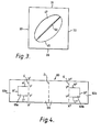
- Figure 4 shows the blank 80 of the cardboard insert 40 before it is assembled.
- the blank 80 is cut along lines A', A'', B', B", and C', C". It is then folded along line D and, in the opposite direction, along lines E between X'-Y' and X"-Y", and to a lesser extent along lines E between Y'-Y' and Y"-Y".
- the length of the cuts A', C', A'' and C'' are half the width of walls 31 or 33, although this may vary to take into account the board thickness and the clearance required during assembly.
- the stack of tissues 10 can then be folded over the central member 55 and the assembly placed inside the carton 20, where it is retained in position by abutment between edges B', B'' of panels 65a, 65b and side walls 30, 32.
Abstract
Description
- This invention relates to dispensers for sheet material, and in particular dispensers for facial tissues.
- Cartons of the kind for dispensing sheet material which is folded on itself into an inverted U-shaped stack are known. The advantages of this kind of carton compared to those which store the sheet material flat, is that they are more compact and require less packaging material and storage space. However, a drawback with cartons of this kind is that the stack of sheet material tends to shift during transportation and use such that the sheets are not properly orientated with the dispensing aperture, giving a potential dispensing problem. British Patent No. 1,186,787 shows a carton in which the stack of tissues is folded on itself. In this arrangement, the end edges of the tissues are flared outwardly so that they bear against the side walls of the carton so as to support the stack and prevent it from shifting.
- To help overcome the problem of shifting, it has been proposed to provide an insert within the carton which supports the tissues. However, it is still possible for the insert itself to shift or for the sheets to become displaced from their correct position over the insert. British Patent No. 1,443,111 shows a carton having an inverted Y-shaped insert over which the stack of sheets is folded. The insert causes the sheets to flare out so that the edges of the tissues bear against the side walls of the carton.
- United States Patent No. 3243079 shows a carton having a W-shaped insert wherein the lateral uprights of the W lie against the side walls of the carton, and wherein the sheets are folded over the central inverted V of the insert and are thus flared out so that the edges of the tissues bear against the lateral uprights of the insert.
- An object of the present invention is to provide a carton having an insert which improves the dispensing properties of the carton and which substantially reduces the shifting of the tissues in the carton during handling and transportation and which is itself prevented from being displaced.
- According to the present invention there is provided a dispenser for sheet material comprising a stack of sheet material, a carton having a base wall, side walls and a top wall, an aperture in the top wall through which the sheet material is dispensed, and support means within the carton for the stack of sheet material, characterised in that said support means comprises a central member projecting substantially vertically upwardly from the base wall, over which the stack of sheet material is folded in the form of a symmetrical inverted U such that the top sheet of the stack is presented to the aperture in the carton; means for supporting the end edges of the folded sheet material; and locating means locating the support means in position in the carton.
- In this way the sheet material is supported in position over the central member which is itself prevented from any substantial shifting within the carton, so that the sheet material is always presented to the aperture for extraction.
- Preferably the means for supporting the end edges of the folded sheet material comprises two wall members which project outwardly and upwardly from either side of the central member, at an angle to the central member, to opposite side walls of the carton, the said angle being advantageously dependent upon the bulk of the sheet material, the number of sheets, the number of plies in each sheet, and the folding configuration. Suitably these wall members extend upwardly from the base wall.
- The whole end edge of each end of the stack is supported in this way since the angle of the two wall members can be varied to match the angle of the end edge of the stack according to the bulk of the sheet material used.
- Preferably the said locating means comprises two members which project substantially horizontally from either side of the central member, along the base wall, to one of the said opposite side walls respectively.
- In this way the central member and the two members for supporting the end edges of the stack are kept in position within the carton without the necessity for additional fixing. Other locating means say be provided, for example the wall members may be provided with tabs which are glued inside the carton.
- Advantageously a plastic film member may be provided, extending across the aperture in the top wall, the said membrane having either an elongate overlapping opening or a slit depending on the nature of the substrate or the fold configuration used to permit extraction of the sheet material from the carton.
- The plastic membrane helps to prevent the sheet material becoming soiled and may also assist in the dispensing action.
- Advantageously the support means is a removable insert which is formed integrally from a cardboard blank.
- The insert used can thereby be changed according to the bulk and length of the sheet material used and the dimensions of the carton.
- Suitably the sheet material may be either interleaved, tab-tied or longitudinally foldedo
- The invention will now be described by way of example and with reference to the accompanying drawings in which:
- Figure 1 is a perspective view of the dispenser according to the present invention;
- Figure 2 is a cross-sectional side view of the dispenser along the line II-II of Figure 1,
- Figure 3 is a view of the dispenser from above showing the plastic film membrane;
- Figure 4 shows the blank for the cardboard insert,
- As shown in Figures 1 and 2, a dispenser for
tissues 10 comprises acarton 20 having abase wall 25,side walls top wall 35 and acardboard insert 40. - The
top wall 35 is provided with anaperture 45 through which thetissues 10 can be extracted. Aplastic film membrane 47 extends across theaperture 45 as shown in Figures 1, 2 and 3. Thismembrane 47 has anelongate opening 50 which is originally sealed for example by perforations so that it can be opened by a user by tearing. - As will be described with reference to Figure 4, the
insert 40 is cut and folded from a single piece of cardboard, and comprises a folded spine forming acentral member 55 projecting vertically upwards centrally from thebase wall 25, and twosupport members central member 55 at an angle A thereto. The upper edges of thesupport members side walls base members central member 55 horizontally along thebase wall 25 respectively to theside walls base members members - Although the
spine 55 is shown as being vertical, it may be substantially vertical and comprise an inverted V-shape, thecentral member 55 and thesupport members - The
tissues 10 are folded over thecentral member 55 in the form of a symmetrical inverted U, so that theuppermost tissue 70 is presented to theaperture 45. Theend edges 75 of thetissues 10 are supported by thesupport members central member 55 should be not more than half the length oftissues 10, and preferably be slightly less that half the length of thetissues 10. The angle A is dependent on the bulk of thetissue 10 used, the sheet count, the ply makeup and the fold configuration. A suitable angle would lie between 45° and 650. - The
tissues 10 of the stack are either interleaved, tab-tied or longitudinally folded as is in itself known. In this way as thetop tissue 70 is extracted the next tissue is pulled partially through theaperture 45 so that it can be grasped by a subsequent user. - In order that the first tissue of a new box can be easily grasped, the top sheet of a complete stack is preferably folded over.
- Figure 4 shows the blank 80 of the
cardboard insert 40 before it is assembled. - To assemble the
insert 40, the blank 80 is cut along lines A', A'', B', B", and C', C". It is then folded along line D and, in the opposite direction, along lines E between X'-Y' and X"-Y", and to a lesser extent along lines E between Y'-Y' and Y"-Y". - The length of the cuts A', C', A'' and C'' are half the width of
walls - The stack of
tissues 10 can then be folded over thecentral member 55 and the assembly placed inside thecarton 20, where it is retained in position by abutment between edges B', B'' ofpanels side walls
Claims (7)
Priority Applications (1)
| Application Number | Priority Date | Filing Date | Title |
|---|---|---|---|
| AT83303191T ATE26911T1 (en) | 1982-06-09 | 1983-06-02 | DISPENSER FOR FOIL MATERIAL. |
Applications Claiming Priority (2)
| Application Number | Priority Date | Filing Date | Title |
|---|---|---|---|
| GB08216754A GB2121765A (en) | 1982-06-09 | 1982-06-09 | A dispenser for sheet material |
| GB8216754 | 1982-06-09 |
Publications (3)
| Publication Number | Publication Date |
|---|---|
| EP0096546A2 true EP0096546A2 (en) | 1983-12-21 |
| EP0096546A3 EP0096546A3 (en) | 1984-12-27 |
| EP0096546B1 EP0096546B1 (en) | 1987-05-06 |
Family
ID=10530920
Family Applications (1)
| Application Number | Title | Priority Date | Filing Date |
|---|---|---|---|
| EP83303191A Expired EP0096546B1 (en) | 1982-06-09 | 1983-06-02 | A dispenser for sheet material |
Country Status (4)
| Country | Link |
|---|---|
| EP (1) | EP0096546B1 (en) |
| AT (1) | ATE26911T1 (en) |
| DE (1) | DE3371277D1 (en) |
| GB (1) | GB2121765A (en) |
Cited By (9)
| Publication number | Priority date | Publication date | Assignee | Title |
|---|---|---|---|---|
| EP0644130A1 (en) * | 1993-09-20 | 1995-03-22 | Kimberly-Clark Corporation | Upright facial tissue carton |
| US6604651B2 (en) | 2001-01-24 | 2003-08-12 | Kimberly-Clark Worldwide, Inc. | Storage and dispensing package for wipes |
| AU781536B2 (en) * | 1999-11-19 | 2005-05-26 | Hanna Match (Australia) Pty. Limited | Sheet dispenser |
| US6946413B2 (en) | 2000-12-29 | 2005-09-20 | Kimberly-Clark Worldwide, Inc. | Composite material with cloth-like feel |
| US7176150B2 (en) | 2001-10-09 | 2007-02-13 | Kimberly-Clark Worldwide, Inc. | Internally tufted laminates |
| US7681756B2 (en) | 2001-01-03 | 2010-03-23 | Kimberly-Clark Worldwide, Inc. | Stretchable composite sheet for adding softness and texture |
| WO2011091414A3 (en) * | 2010-01-25 | 2012-01-12 | Ranpak Corp. | Compact dunnage storage and conversion system |
| WO2012096756A1 (en) * | 2011-01-14 | 2012-07-19 | Ranpak Corp. | Compact dunnage dispensing system and method |
| US8573398B2 (en) | 2002-05-28 | 2013-11-05 | Georgia-Pacific Consumer Products Lp | Refillable flexible sheet dispenser |
Families Citing this family (2)
| Publication number | Priority date | Publication date | Assignee | Title |
|---|---|---|---|---|
| DE20212989U1 (en) | 2002-08-23 | 2003-01-02 | Carl Huebenthal Kg | Foil pack for stacked towels |
| US6840401B2 (en) | 2002-12-19 | 2005-01-11 | Kimberly-Clark Worldwide, Inc. | Multiple layer baffle structure for dispenser for wipes |
Citations (3)
| Publication number | Priority date | Publication date | Assignee | Title |
|---|---|---|---|---|
| US3090522A (en) * | 1961-07-03 | 1963-05-21 | Ernest F Hohwart | Napkin dispenser |
| US3624791A (en) * | 1970-01-09 | 1971-11-30 | Instrument Systems Corp | A dispensing package for plastic bags and the like |
| GB1443111A (en) * | 1973-07-11 | 1976-07-21 | Procter & Gamble | Compact dispensing package |
Family Cites Families (3)
| Publication number | Priority date | Publication date | Assignee | Title |
|---|---|---|---|---|
| US3243079A (en) * | 1964-06-22 | 1966-03-29 | Viking Plastics Inc | Dispensing package of plastic gloves |
| GB1269157A (en) * | 1969-05-27 | 1972-04-06 | Augustus Mierson | Bag dispenser |
| US3596798A (en) * | 1969-07-07 | 1971-08-03 | Buford B Smith | Dispensing carton for sheet-form articles |
-
1982
- 1982-06-09 GB GB08216754A patent/GB2121765A/en not_active Withdrawn
-
1983
- 1983-06-02 EP EP83303191A patent/EP0096546B1/en not_active Expired
- 1983-06-02 AT AT83303191T patent/ATE26911T1/en not_active IP Right Cessation
- 1983-06-02 DE DE8383303191T patent/DE3371277D1/en not_active Expired
Patent Citations (3)
| Publication number | Priority date | Publication date | Assignee | Title |
|---|---|---|---|---|
| US3090522A (en) * | 1961-07-03 | 1963-05-21 | Ernest F Hohwart | Napkin dispenser |
| US3624791A (en) * | 1970-01-09 | 1971-11-30 | Instrument Systems Corp | A dispensing package for plastic bags and the like |
| GB1443111A (en) * | 1973-07-11 | 1976-07-21 | Procter & Gamble | Compact dispensing package |
Cited By (13)
| Publication number | Priority date | Publication date | Assignee | Title |
|---|---|---|---|---|
| FR2710251A1 (en) * | 1993-09-20 | 1995-03-31 | Kimberly Clark Co | Vertical box of tissues. |
| EP0644130A1 (en) * | 1993-09-20 | 1995-03-22 | Kimberly-Clark Corporation | Upright facial tissue carton |
| AU781536B2 (en) * | 1999-11-19 | 2005-05-26 | Hanna Match (Australia) Pty. Limited | Sheet dispenser |
| US6946413B2 (en) | 2000-12-29 | 2005-09-20 | Kimberly-Clark Worldwide, Inc. | Composite material with cloth-like feel |
| US7681756B2 (en) | 2001-01-03 | 2010-03-23 | Kimberly-Clark Worldwide, Inc. | Stretchable composite sheet for adding softness and texture |
| US6604651B2 (en) | 2001-01-24 | 2003-08-12 | Kimberly-Clark Worldwide, Inc. | Storage and dispensing package for wipes |
| US7176150B2 (en) | 2001-10-09 | 2007-02-13 | Kimberly-Clark Worldwide, Inc. | Internally tufted laminates |
| US7879172B2 (en) | 2001-10-09 | 2011-02-01 | Kimberly-Clark Worldwide, Inc. | Methods for producing internally-tufted laminates |
| US8573398B2 (en) | 2002-05-28 | 2013-11-05 | Georgia-Pacific Consumer Products Lp | Refillable flexible sheet dispenser |
| WO2011091414A3 (en) * | 2010-01-25 | 2012-01-12 | Ranpak Corp. | Compact dunnage storage and conversion system |
| US20120283084A1 (en) * | 2010-01-25 | 2012-11-08 | Ranpak Corp. | Compact dunnage storage and conversion system |
| CN104071396A (en) * | 2010-01-25 | 2014-10-01 | 兰帕克公司 | Compact dunnage storage and conversion system |
| WO2012096756A1 (en) * | 2011-01-14 | 2012-07-19 | Ranpak Corp. | Compact dunnage dispensing system and method |
Also Published As
| Publication number | Publication date |
|---|---|
| ATE26911T1 (en) | 1987-05-15 |
| EP0096546A3 (en) | 1984-12-27 |
| EP0096546B1 (en) | 1987-05-06 |
| DE3371277D1 (en) | 1987-06-11 |
| GB2121765A (en) | 1984-01-04 |
Similar Documents
| Publication | Publication Date | Title |
|---|---|---|
| US4899929A (en) | Self-erecting container with removable section | |
| US3036729A (en) | Dispensing package | |
| US4396143A (en) | Multiple article beverage package | |
| US5356022A (en) | Container for toxic waste | |
| EP1075436B1 (en) | A tissue box | |
| US2529853A (en) | Folded tissues and dispenser therefor | |
| US20030150759A1 (en) | Carrying carton and can dispenser | |
| US3066843A (en) | Shipping and/or dispensing container | |
| EP1587744B1 (en) | Dispensing carton for sheet products | |
| EP0088597A2 (en) | Sheet and envelope therefor | |
| US3224633A (en) | Collapsible box for facial tissues | |
| US4163508A (en) | Disposable cup dispenser | |
| EP0096546B1 (en) | A dispenser for sheet material | |
| US3370776A (en) | Dispenser package | |
| US7275657B2 (en) | Bag dispenser | |
| EP1066199A1 (en) | Trays | |
| US3395830A (en) | Dispensing carton suitable for plastic bags and the like | |
| US3743151A (en) | Paperboard dispenser for tape | |
| US7134572B2 (en) | Container for a stack of interfolded tissue sheets | |
| US3309834A (en) | Dispensing carton suitable for plastic bags and the like | |
| US3195772A (en) | Dispensing carton suitable for plastic bags and the like | |
| US4913311A (en) | Soap leaf dispensing system | |
| US3820686A (en) | Dispenser carton and blank for forming same | |
| GB2319241A (en) | A dispensing tray | |
| US20200156861A1 (en) | Floating roll end holders |
Legal Events
| Date | Code | Title | Description |
|---|---|---|---|
| PUAI | Public reference made under article 153(3) epc to a published international application that has entered the european phase |
Free format text: ORIGINAL CODE: 0009012 |
|
| AK | Designated contracting states |
Designated state(s): AT BE CH DE FR GB IT LI LU NL SE |
|
| PUAL | Search report despatched |
Free format text: ORIGINAL CODE: 0009013 |
|
| AK | Designated contracting states |
Designated state(s): AT BE CH DE FR GB IT LI LU NL SE |
|
| 17P | Request for examination filed |
Effective date: 19850626 |
|
| 17Q | First examination report despatched |
Effective date: 19860327 |
|
| GRAA | (expected) grant |
Free format text: ORIGINAL CODE: 0009210 |
|
| AK | Designated contracting states |
Kind code of ref document: B1 Designated state(s): AT BE CH DE FR GB IT LI LU NL SE |
|
| REF | Corresponds to: |
Ref document number: 26911 Country of ref document: AT Date of ref document: 19870515 Kind code of ref document: T |
|
| REF | Corresponds to: |
Ref document number: 3371277 Country of ref document: DE Date of ref document: 19870611 |
|
| PG25 | Lapsed in a contracting state [announced via postgrant information from national office to epo] |
Ref country code: LU Free format text: LAPSE BECAUSE OF NON-PAYMENT OF DUE FEES Effective date: 19870630 |
|
| PGFP | Annual fee paid to national office [announced via postgrant information from national office to epo] |
Ref country code: NL Payment date: 19870630 Year of fee payment: 5 |
|
| ITF | It: translation for a ep patent filed |
Owner name: JACOBACCI & PERANI S.P.A. |
|
| ET | Fr: translation filed | ||
| PLBE | No opposition filed within time limit |
Free format text: ORIGINAL CODE: 0009261 |
|
| STAA | Information on the status of an ep patent application or granted ep patent |
Free format text: STATUS: NO OPPOSITION FILED WITHIN TIME LIMIT |
|
| 26N | No opposition filed | ||
| PG25 | Lapsed in a contracting state [announced via postgrant information from national office to epo] |
Ref country code: AT Effective date: 19880602 |
|
| PG25 | Lapsed in a contracting state [announced via postgrant information from national office to epo] |
Ref country code: SE Effective date: 19880603 |
|
| PG25 | Lapsed in a contracting state [announced via postgrant information from national office to epo] |
Ref country code: LI Effective date: 19880630 Ref country code: CH Effective date: 19880630 |
|
| PG25 | Lapsed in a contracting state [announced via postgrant information from national office to epo] |
Ref country code: DE Effective date: 19880810 |
|
| BERE | Be: lapsed |
Owner name: BOWATER-SCOTT CORP. LTD Effective date: 19880630 |
|
| PG25 | Lapsed in a contracting state [announced via postgrant information from national office to epo] |
Ref country code: NL Effective date: 19890101 |
|
| NLV4 | Nl: lapsed or anulled due to non-payment of the annual fee | ||
| PG25 | Lapsed in a contracting state [announced via postgrant information from national office to epo] |
Ref country code: FR Free format text: LAPSE BECAUSE OF NON-PAYMENT OF DUE FEES Effective date: 19890228 |
|
| REG | Reference to a national code |
Ref country code: CH Ref legal event code: PL |
|
| REG | Reference to a national code |
Ref country code: FR Ref legal event code: ST |
|
| PG25 | Lapsed in a contracting state [announced via postgrant information from national office to epo] |
Ref country code: BE Effective date: 19890630 |
|
| PGFP | Annual fee paid to national office [announced via postgrant information from national office to epo] |
Ref country code: GB Payment date: 19920520 Year of fee payment: 10 |
|
| PG25 | Lapsed in a contracting state [announced via postgrant information from national office to epo] |
Ref country code: GB Effective date: 19930602 |
|
| GBPC | Gb: european patent ceased through non-payment of renewal fee |
Effective date: 19930602 |
|
| EUG | Se: european patent has lapsed |
Ref document number: 83303191.7 Effective date: 19890220 |