EP0095926A2 - Microsurgical system cassette assembly - Google Patents
Microsurgical system cassette assembly Download PDFInfo
- Publication number
- EP0095926A2 EP0095926A2 EP83303109A EP83303109A EP0095926A2 EP 0095926 A2 EP0095926 A2 EP 0095926A2 EP 83303109 A EP83303109 A EP 83303109A EP 83303109 A EP83303109 A EP 83303109A EP 0095926 A2 EP0095926 A2 EP 0095926A2
- Authority
- EP
- European Patent Office
- Prior art keywords
- conduit
- cassette assembly
- section
- instrument
- occludable
- Prior art date
- Legal status (The legal status is an assumption and is not a legal conclusion. Google has not performed a legal analysis and makes no representation as to the accuracy of the status listed.)
- Granted
Links
Images


Classifications
-
- A—HUMAN NECESSITIES
- A61—MEDICAL OR VETERINARY SCIENCE; HYGIENE
- A61F—FILTERS IMPLANTABLE INTO BLOOD VESSELS; PROSTHESES; DEVICES PROVIDING PATENCY TO, OR PREVENTING COLLAPSING OF, TUBULAR STRUCTURES OF THE BODY, e.g. STENTS; ORTHOPAEDIC, NURSING OR CONTRACEPTIVE DEVICES; FOMENTATION; TREATMENT OR PROTECTION OF EYES OR EARS; BANDAGES, DRESSINGS OR ABSORBENT PADS; FIRST-AID KITS
- A61F9/00—Methods or devices for treatment of the eyes; Devices for putting-in contact lenses; Devices to correct squinting; Apparatus to guide the blind; Protective devices for the eyes, carried on the body or in the hand
- A61F9/007—Methods or devices for eye surgery
- A61F9/00736—Instruments for removal of intra-ocular material or intra-ocular injection, e.g. cataract instruments
-
- A—HUMAN NECESSITIES
- A61—MEDICAL OR VETERINARY SCIENCE; HYGIENE
- A61B—DIAGNOSIS; SURGERY; IDENTIFICATION
- A61B17/00—Surgical instruments, devices or methods, e.g. tourniquets
- A61B2017/00973—Surgical instruments, devices or methods, e.g. tourniquets pedal-operated
- A61B2017/00977—Surgical instruments, devices or methods, e.g. tourniquets pedal-operated the depression depth determining the power rate
-
- A—HUMAN NECESSITIES
- A61—MEDICAL OR VETERINARY SCIENCE; HYGIENE
- A61M—DEVICES FOR INTRODUCING MEDIA INTO, OR ONTO, THE BODY; DEVICES FOR TRANSDUCING BODY MEDIA OR FOR TAKING MEDIA FROM THE BODY; DEVICES FOR PRODUCING OR ENDING SLEEP OR STUPOR
- A61M1/00—Suction or pumping devices for medical purposes; Devices for carrying-off, for treatment of, or for carrying-over, body-liquids; Drainage systems
- A61M1/71—Suction drainage systems
- A61M1/77—Suction-irrigation systems
-
- A—HUMAN NECESSITIES
- A61—MEDICAL OR VETERINARY SCIENCE; HYGIENE
- A61M—DEVICES FOR INTRODUCING MEDIA INTO, OR ONTO, THE BODY; DEVICES FOR TRANSDUCING BODY MEDIA OR FOR TAKING MEDIA FROM THE BODY; DEVICES FOR PRODUCING OR ENDING SLEEP OR STUPOR
- A61M2205/00—General characteristics of the apparatus
- A61M2205/12—General characteristics of the apparatus with interchangeable cassettes forming partially or totally the fluid circuit
Definitions
- the foot switch 62 also includes a button 66 for controlling the operation of the cutting unit 26.
- a pair of LED displays 72 and 74 are provided on the I/A unit's front panel to indicate preset and existing vacuum conditions.
- the I/A unit is also arranged to control the flow of infusion liquid through the cassette assembly 20 from the liquid source to the surgical situs.
- three push-button knobs 76, 78 and 80 are provided on the front panel of the I/A unit.
- "Button 76 is the “off” button and, when depressed, causes an infusion interruptor bar 82 (Fig. 2) in the I/A unit to close the infusion liquid flow path in the cassette assembly to stop the flow of liquid to the surgery situs.
- Button 78 is the "on” button and, when depressed, holds the interruptor bar 82 in a position so that the infusion path in the cassette is open to allow the flow of infusion liquid to the surgery situs.
- the upper section 104 of the housing includes a planar bottom wall 170, a front wall 172, a top wall 174 and a pair of sidewalls 176.
- a pair of ribs project downward from the outer surface of the bottom wall 170 along each of the sidewalls 176 for receipt within respective slots 178 (Fig. 4) in the top edge of the back wall 152 of the lower section 106.
- a pair of elongated stops 200 and 202 project upward from the bottom wall 148 of the lower section 106.
- the stops cooperate with the interruptor bars to squeeze or occlude the suction and infusion conduit sections therebetween upon operation of the interrupter bars, as will be described later.
- Wall section 210 projects inward from the top section's front wall 172, upward from its bottom wall 170 and in alignment with the infusion input luer 108.
- wall section 212 projects inward from the top section's front wall 104, upward from its bottom wall 170 and,in alignment with the infusion output luer 110.
- the wall section 210 includes a horizontal passageway portion 214 and a communicating vertical passageway portion 216. Passageway portion 214 is in communication with the interior of luer 103.
- infusion liquid in enabled to flow through the cassette assembly in the direction of the arrows denoted by the reference numerals 240 in Figs. 4, 5 and 7 as follows: into luer 108, through passageway sections 214, and 216, through L-snaped connector 224, through infusion conduit section 122, through L-shaped connector 232, through passageways 220 and 218 to outlet luer 110.
- a second circular sidewall 250 is located within the interior of the upper housing section 104 as shown in Fig. 8.
- the sidewall 250 is arranged to form a chamber to receive the check valve 116.
- At the mouth of the sidewall 250 is an annular ledge 252 adapted to receive the sidewall 254 of a bucket-shaped cap 256.
- the cap 256 holds the check valve in place within the circular sidewall 250.
- the space between legs of adjacent V -shaped splines is denoted by the reference numeral 322 and is in communication with the outlet 300.
- the diameter of the diaphragm 320 is slightly less than the length of -the convex surface of the splines measured in the diametric direction.
- fluid e.g., air
- the communicating spaces 322 around the periphery of the diaphragm 320 to opening 310 and from thence through the open electronic valve within the I/A unit to allow the venting of suction line 56 to the atmosphere through the open electronic valve when desired.
- the means for interrupting the vacuum in the suction line and a means for interrupting the flow of infusion line consists of the heretofore mentioned interrupter bars 70 and 82, respectively. As also mentioned heretofore, each of those bars is arranged to engage an associated portion of the conduit section to close or occlude the conduit section, thereby interrupting the flow therethrough.
- the back wall 152 of the lower housing section includes a pair of openings 330 and 332. Each opening is larger at its entrance than at its exit.
- the opening 330 is disposed opposite to the stop 200.
- the opening 332 is disposed opposite to the stop 202.
- the interrupter bar 70 is arranged to be reciprocated through the opening 330 into the interior of the lower section to engage the suction conduit section 120 disposed contiguous with that opening to squeeze or occlude that portion of the conduit section against the stop 200. This action immediately interrupts suction in suction line 56.
- the electronic valve and the I/A unit opens, whereupon the suction line 56 is vented to the atmosphere, via the check valve and associated electronic vent valve.
- the check valve operates as noted heretofore, to prevent any egress of material into the electronic vent valve.
- the extension of the infusion interruptor bar 82 can be accomplished either in response to the depression of the "close” button 76 on the front panel of the I/A unit or can be under control of the foot switch 62 when the I/A unit is in the "automatic" mode as established by the depression of the push-button 80.
- the push-button 78 of the I/A unit is depressed, the unit is in the "open” state with the interrupter bar retracted so long as the "open” button 78 is depressed.
- a sleeve 362 extends through the central opening 364 in the back wall of the bucket member of the cassette assembly and receives the flanged lip 312 of the check valve to provide a passage to the interior of the check valve.
- the free end of the sleeve 362 is rounded at 366. This sleeve is adapted to fit into the passageway in the I/A unit's recess 360 to provide access to the electronic vent valve therein (not shown).
Abstract
Description
- This invention relates generally to surgical instruments, and more particularly, to microsurgical instruments.
- Microsurgical systems are gaining ever-increasing acceptance in the surgical community for performing precise, minimum invasive surgery for various parts of the body. One particularly widespread microsurgical application is in the field of ophthalmology, and various manufacturers now produce opthalmic microsurgical systems. Examples of such syststems are the Model 8000V system of Cavitron/Kelman and the Occutome II/Fragmatome II system of Cooper Medical Devices Corporation. Such systems have been used for performing anterior as well as posterior chamber surgery.
- In either type of surgery, a remote handpiece having a small tool is used to either cut or mascerate the eye tissue while an irrigation or infusion liquid, such as Ringer solution, is brought to the situs of the surgery within the eye. The cut or mascerated tissue (detrius) is carried away from the surgical situs by a suction conduit or tube (which may or may not be connected to the tool) to some sort of collection vessel, e.g., a bag or bottle, located at the instrument or remote therefrom.
- The suction produced in the suction conduit or line is usually controlled by the surgeon, via some switch means, e.g., a foot switch, so that the vacuum can be interrupted, when desired, during the surgery. In many applications it is also desireable to halt the flow of the infusion liquid upon the interruption of the suction line. The means for interrupting the infusion usually consists of an on/off valve or switch in the infusion line.
- Heretofore, various prior art microsurgical systems have been arranged for receipt of portions of the suction line into a pinch valve in the instrument so that when the suction flow is to be stopped, the pinch valve occludes the line.
- 'It will be appreciated by those skilled in the art that when the suction line is occluded, the inertia of the material within the line upstream of the occlusion point continues to produce suction at the entrance to the suction conduit. This residual vacuum can present substantial hazard in"ophthalmic surgery applications, and particularly in anterior surgery applications since the anterior chamber is of much smaller volume than the posterior chamber. Thus, the residual or continued vacuum at the entrance to the suction line after the surgeon acts to interrupt the suction can result in the excessive evacuation of fluid from the anterior chamber or can result in the snagging and concomitant damage of delicate eye tissue.
- In view of the foregoing and in the interest of surgical efficiency and patient safety, it is of considerable importance that there be precise control of.the start-up and interruption of the vacuum in the suction line, while also insuring that upon the vacuum interruption, the suction line is neutralized to overcome any residual suction and inertial effects. In this regard, some microsurgical systems have incorporated venting means in the instrument itself to vent the suction line to the atmosphere when the suction line is occluded. Such systems also make use of replaceable hydrophobic filter means which is disposed in the instrument to prevent any material in the collection vessel from gaining ingress into the means which produce the vacuum, e.g., the vacuum pump.
- While prior art microsurgical systems and techniques are generally suitable for their intended purposes, they leave much to be desired from the standpoint of simplicity of construction and use, and efficiency of operation. For example, with the prior art microsurgical systems described heretofore, it is necessary to connect the individual components making up the system, e.g., the filters, valves, collection bags or bottles, tubing, etc., to the instrument. Such preoperative setup procedures require substantial time, are complicated, messy and susceptible to error.
- Accordingly, it is the general object of this invention to provide in a microsurgical system an integrated cassette assembly which overcomes the disadvantages of the prior art.
- It is a further object of this invention to provide in a microsurgical system a cassette assembly which integrates various functions of prior art microsurgical systems into a simple, ready-to-use, effective unit.
- It is a further object of this invention to provide in a microsurgical system a cassette assembly which can be readily connected to a microsurgical instrument to effect the immediate properative setup of suction and/or infusion conduits.
- It is still a further object of this invention to provide for use in a microsurgical system an integrated cassette assembly incorporating a collector vessel, suction and infusion interrupter means, venting means and filter means.
- It is still a further object of this invention to provide in a microsurgical system a disposable cassette assembly which is simple in construction and low in cost.
- These and other objects of the instant invention are achieved by providing a cassette assembly for use in a microsurgical system comprising an instrument having control means, remotely connected means adapted to be disposed in the vicinity of the surgery situs and including an aperture, and first conduit means coupled to the aperture and arranged for carrying a fluid therethrough. The control means includes first means cooperating with the cassette assembly for selectively precluding the fluid from flowing through the first conduit. The cassette assembly is arranged for releasable securement to the instrument and comprises first port means for communication with the first conduit means, second port means through which the fluid flows and first occludable means coupled between the first and second port means. The first occludable means is arranged for cooperation with the first means when the cassette assembly is secured to the instrument to isolate the first and second ports from each other in response to a first signal, thereby precluding the fluid from flowing therethrough and through the first conduit means.
- Other objects and many of the attendant advantages of this invention will be readily appreciated as the same becomes better understood by reference to the following detailed description when considered in connection with the accompanying drawing wherein:
-
- Fig. 1 is a perspective view of a microsurgical system including the cassette assembly of the instant invention;
- Fig. 2 is an enlarged, exploded perspective view of a portion of the microsurgical system and the cassette assembly shown in Fig. 1;
- Fig. 3 is an enlarged perspective view of the cassette assembly shown in Figs. 1 and 2;
- Fig. 4 is an enlarged sectional view taken along line 4-4 of Fig. 3;
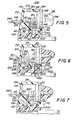
- Fig. 5 is a sectional view taKen along line 5-5 of Fig. 4;
- Fig. 6 is a sectional view taken along line 6-6 of Fig. 4;
- Fig. 7 is a sectional view taken along line 7-7 of Fig. 4;
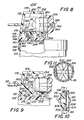
- Fig. 8 is a sectional view taken along line 8-8 of Fig. 4;
- Fig. 9 is a sectional view taken along line 9-9 of Fig. 4;
- Fig. 10 is a sectional view of a check valve forming a portion of the cassette assembly of the instant invention; and
- Fig. 11 is a sectional view taken along line 11-11 of Fig. 10.
- Referring now to various figures of the drawing wherein like reference characters refer to like parts, there is shown generally at 20 in Fig. 1 a cassette assembly for use in a microsurgical system. The system shown in Fig. 1 is a complete microsurgical system suitable for a wide variety of ophthalmic surgical applications. To that end, the
complete system 20 basically comprises aninstrument 22 having a console including plural modular units, such as an ultrasonic (fragmentation)unit 24, acutting unit 26, an infusion/aspiration or I/A unit 28 and a fiberoptic.unit 30. ' - The basic building block of the system consists of the I/
A unit 28. This unit is arranged for performing extracapsular cataract procedures as well as other surgical procedures. If anterior segment surgery is required, thecutting unit 26 is added to the console. The addition of the fiber optic unit renders the system suitable for both pars plana and anterior segment intraocular microsurgery. Finally, if lens emulsification or aspiration is desired, theultrasonic unit 24 is added to the console. - The
cassette assembly 20 of the instant invention is arranged for use with the I/A unit 28 of the instrument. Thus, the details and features of theultrasonic unit 24, thecutting unit 26 and the fiberoptic unit 30 will not be described herein. Suffice to say that theultrasonic unit 24 is arranged to operate and drive a remote hand-held ultrasonic (fragmentation) tool (not shown), via a connectingcable 32. The amount of ultrasonic . _ energy provided to the tool is established by the setting of arotary adjustment knob 34 on the unit's front panel. A pair of on/off switches 36 andLED display 38 are also provided on the unit's front panel. The LED display provides an indication of the ultrasonic energy provided to the tool. - The
cutting unit 26 is arranged to drive atool 40 mounted in ahandpiece 42, via a communicatingcable 44. Thetool 40 can be of any suitable types, such as a reciprocating cutter, a rotary cutter, a guillotine cutter, a scissors, etc. The speed of the cutting action is established by the setting of arotary knob 46 on the cutting unit's front panel. On/off andother switches 48 are also provided on the front panel. The front panel also includes aLED display 50 for indicating operating speed. - The fiber
optic illumination unit 30 provides variable, cool white, illumination for intraocular procedures and for intraocular photography. To that end,unit 30 comprises a light source (not shown) located within the unit for producing the white light. The light is provided, via a fiber optic cable (not shown), to the surgical situs. The cable is connected by aconnector coupling 52 on the front panel of theillumination unit 30. The intensity of illumination provided by theunit 30 is established by the setting of arotary adjustment knob 54 on the front panel of theunit 30. - The I/
A unit 28 controls the removal of the cut or mascerated tissue produced by the operation of thecutting tool 40 or by the ultrasonic tool (not shown), while also controlling infusion of liquid into the surgery situs. In particular,unit 28 produces a vacuum in a suction conduit ortube 56 which is connected between thecassette assembly 20 and thecutting tool handpiece 42 or some other means, e.g., a needle (not shown), arranged to be located at the surgery situs. An infusion liquid, such as a Ringer solution, is provided to the surgery situs, via a conduit ortube 58 connected between thecassette assembly 20 and thehandpiece 42 or some other means, e.g., a needle, located at the surgery situs. The infusion liquid is supplied to the cassette assembly from a supply bottle (not shown), via aconduit 60. As will be described in detail later, the I/A unit 28 includes means which cooperates with means in the cassette assembly to enable or disable the suction and/or the infusion under control of the surgeon. - During surgery the cutting action of the
tool 40 mascerates or cuts the tissue at the operating situs. The mascerated tissue and the liquid infused into the operating situs, vialine 58, is carried by thesuction line 56 away from the situs to the cassette assembly for collection in its collection bottle. The vacuum in the suction line is produced by a pump (not shown) in the I/A unit and is coupled, via means in the cassette assembly, to thesuction line 56, as will.be described later. The degree of vacuum in the suction line can be varied linearly by the surgeon by the depression offoot switch 62 connected by acable 64 to theinstrument 22. - Accordingly, when the
foot switch 62 is depressed fully, the amount of vacuum produced in the I/A suction line is at the value as established by the setting of an adjustable control knob 68 on the unit's front panel. When thefoot switch 62 is released partially, the amount of vacuum in the suction line is a portion of the maximum as established by the setting of knob 68. When the foot switch is fully released, the I/A unit immediately interrupts the vacuum in the suction line by the operation of its suction interrupter bar 72 (Fig. 2) closing the suction path in thecassette assembly 20. - The
foot switch 62 also includes abutton 66 for controlling the operation of the cuttingunit 26. A pair of LED displays 72 and 74 are provided on the I/A unit's front panel to indicate preset and existing vacuum conditions. - As stated earlier, the I/A unit is also arranged to control the flow of infusion liquid through the
cassette assembly 20 from the liquid source to the surgical situs. To that end, three push-button knobs 76, 78 and 80 are provided on the front panel of the I/A unit. "Button 76 is the "off" button and, when depressed, causes an infusion interruptor bar 82 (Fig. 2) in the I/A unit to close the infusion liquid flow path in the cassette assembly to stop the flow of liquid to the surgery situs. Button 78 is the "on" button and, when depressed, holds theinterruptor bar 82 in a position so that the infusion path in the cassette is open to allow the flow of infusion liquid to the surgery situs. The push-button 80 is the "automatic" button and, when depressed, gives control of the operation of theinterruptor bar 82 over to thefoot switch 62. Accordingly, when the I/A unit is in the automatic mode, release of the foot switch by the surgeon causes theinterruptor bar 82 to operate to interrupt the flow of infusion liquid to the surgery situs. - The I/A unit includes a large cove or
receiver 84 for receipt and mounting of thecassette assembly 20. The cassette assembly includes means which cooperates with means in the receiver for releasably mounting the assembly in the I/A receiver. - Turning now to Figs. 2-11, the details of the
cassette assembly 20 will be described. Basically the cassette assembly comprises a body orhousing 100, and acollector bottle 102 depending therefrom. The housing includes various components, to be described later, and is made up of a pair of mating, molded plastic sections, namely, anupper section 104 and alower section 106. As can be seen in Fig. 3, theupper section 104 includes an infusionliquid input port 108, in the form of a female luer to which theconduit 60 is secured, an infusionliquid output port 110, in the form of a male luer to which theconduit 58 is secured, and asuction port 112, in the form of a male luer to which thesuction conduit 56 is secured. - A hydrophobic filter 114 (Fig. 2) is mounted within the upper section of the housing and is arranged when the
cassette assembly 22 is located within the I/A unit'sreceiver 84 to communicate with the vacuum producing pump (not shown) in the unit. Thefilter 114 is a conventional device, such as a Millex-FG filter made by Millipore.Filter 114 is arranged to prevent any liquid from entering into the pump, while also precluding any bacteria in the I/A unit from gaining ingress into the cassette assembly. - A one-
way check valve 116 is also mounted within theupper section 104 of the cassette assembly housing. The check valve is arranged to communicate with an electronic vent valve (not shown) within the I/A unit when the cassette is mounted within the unit's receiver. The electronic valve is of conventional construction and allows the suction line to vent to the atmosphere, upon the interruption of the vacuum. This action neutralizes the vacuum in the suction'line, thereby obviating any residual vacuum effects which could occur by the inertia of the liquid in the line at the moment the vacuum is interrupted. Thecheck valve 116 permits the venting to occur through the electronic valve while precluding any liquid or material in the suction line from entering into that valve. - As stated earlier, the
cassette assemby 20 includes passageway means for the suction line and the infusion line which are acted upon interruptor bars 70 and 82, respectively, to interrupt the fluid flows therethrough, under the control of the I/A unit. Such passageway means comprise a pair ofoccludable conduit sections - The
suction conduit section 120 is connected in series in the path of the suction line between the port 1'12 and thecollection bottle 102. The collection bottle is in turn connected in the suction path between thefilter 114 and thesuction conduit section 120. Thecheck valve 116 is connected to the junction of thesuction port 112 and thesuction conduit section 120 to enable the venting of the suction line downstream of the collection bottle upon the interruption of the suction by the I/A unit'sinterruptor bar 70. - The
infusion conduit section 122 is connected betweeninfusion output port 110 and theinfusion input port 108. - As shown clearly in Figs. 4-9, the
lower section 106 of the housing basically comprises abottom wall 148 of generally rectangular shape having afront wall 150, arear wall 152 and a pair ofsidewalls 154 projecting upward about the periphery thereof. Acircular cap portion 156 is disposed contiguous with the bottom wall and basically comprises a circular sidewall including internalhelical threads 158. A rubber gasket in the form of aring 160 is located at the inside interface of thesidewall 156 and the top of the cap (Fig. 8). A downward projectingannular flange 162 holds the gasket ring in place. The - periphery of thecollection bottle 102 includeshelical threads 164 disposed thereabout to mate with thethreads 158 on the cap to enable the bottle to be screwed into place in the cap. - The
upper section 104 of the housing includes a planarbottom wall 170, afront wall 172, atop wall 174 and a pair ofsidewalls 176. A pair of ribs (not shown) project downward from the outer surface of thebottom wall 170 along each of thesidewalls 176 for receipt within respective slots 178 (Fig. 4) in the top edge of theback wall 152 of thelower section 106. When the sections are secured together, thesidewalls front wall portions - Referring now to Figs. 5-7, it can be seen that in the interior of the
upper section 104 there is acircular sidewall 180 forming acylindrical cavity 182. The mouth of the cavity includes anannular ledge 184 adapted to receive thefilter 114. As can be seen, thefilter 114 includes a disk-like portion which is disposed onledge 184. Thesidewall 180 also includes a secondannular ledge 186 contiguous with the back of thetop wall 174 andbottom wall 170. Thefilter 114 also includes anentrance port 190 in the form of a female luer, which is in open communication with the interior ofchamber 182 and anoutlet port 192, in the form of a male luer adapted to be received within apassage 194 in the I/A unit'sreceiver 84. Thepassageway 194 communicates with the electronic vent valve in the I/A unit. A ring-like wafer 188 is mounted on theledge 186, with theoutlet luer 192 extending therethrough, to hold the filter in place in the chamber orcavity 182. - As can be seen in Fig. 4, a pair of
elongated stops bottom wall 148 of thelower section 106. The stops cooperate with the interruptor bars to squeeze or occlude the suction and infusion conduit sections therebetween upon operation of the interrupter bars, as will be described later. - As can be seen in Fig. 6, a
suction aperture 204 extends through thebottom wall 150 of the bottom section and terminates in atubular chimney section 206 projecting upward from thebackstop 200. The upper portion of thechimney section 206 extends into anopening 208 in thebottom wall 170 of the top section. Thus, thesuction aperture 204 provides fluid communication between the interior of thecollection bottle 102 and the interior of thefilter chamber 182. - As can be seen in Figs. 5-7, disposed within the interior of the
chamber 182 are a pair ofwall sections 210 and 212 (Figs. 5 and 6).Wall section 210 projects inward from the top section'sfront wall 172, upward from itsbottom wall 170 and in alignment with theinfusion input luer 108. In a similar manner, thewall section 212 projects inward from the top section'sfront wall 104, upward from itsbottom wall 170 and,in alignment with theinfusion output luer 110. Thewall section 210 includes ahorizontal passageway portion 214 and a communicatingvertical passageway portion 216.Passageway portion 214 is in communication with the interior of luer 103. In a similar manner, thewall section 212 includes ahorizontal passageway portion 218 and avertical passageway portion 220. Thehorizontal passageway portion 218 is in communication with the interior of themale luer 110. The lower end ofpassageway section 216 is in the form of anenlarged mouth 222 for receipt of the upwardly extending leg of a tubular, .L-shapedconnector 224. The connector rests on a circular ledge or pad 226 projecting upward from the top surface of thebottom wall 148 of the lower housing section. The other end of the L-shapedconnector 224 is disposed within oneend 228 of theinfusion conduit section 122. - In a similar manner, the lower end of
passageway 220 is in the form of anenlarged mouth 230. Themouth 230 receives the upper section of an L-shaped,tubular connector 232. The other end ofconnector 232 is located within theend 236 of theinfusion conduit section 122.Connector 232 rests on a circular ledge or pad 234 projecting upward from the top surface of thebottom wall 148 of thelower section 106. - As will be appreciated from the foregoing, infusion liquid in enabled to flow through the cassette assembly in the direction of the arrows denoted by the
reference numerals 240 in Figs. 4, 5 and 7 as follows: intoluer 108, throughpassageway sections snaped connector 224, throughinfusion conduit section 122, through L-shapedconnector 232, throughpassageways outlet luer 110. - A second
circular sidewall 250 is located within the interior of theupper housing section 104 as shown in Fig. 8. Thesidewall 250 is arranged to form a chamber to receive thecheck valve 116. At the mouth of thesidewall 250 is anannular ledge 252 adapted to receive thesidewall 254 of a bucket-shapedcap 256. Thecap 256 holds the check valve in place within thecircular sidewall 250. - A
wall section 260 projects inward from the top section'sfront wall 172, upward from itsbottom wall 170 and aligned with thesuction luer 112. Thewall section 260 includes a horizontal passageway 262 in communication with the interior of theluer 112 at one end thereof and terminating in anopening 264 at the back edge of thewall section 260. Theopening 264 is arranged to communicate with thecheck valve 116 to allow venting of the suction line, as will be described later. Avertical passageway 266 communicates with the horizontal passageway 262 in thewall section 260. The lower end ofpassageway 266 includes anenlarged bore 268 adapted to recieve the upper end of an L-shapedconduit connector 270. The other end of theconnector 270 is disposed within one end of 274 of thesuction conduit section 120. Theconnector 270 rests upon a circular ledge or pad 272 projecting upward from thebottom wall 148 of the lower section. Theother end 276 of thesuction conduit section 120 receives one end of an L-shaped,tubular connector 278. The other end ofconnector 278 is received within abore 282 in a circular ledge or pad 280 projecting upward from thebottom wall 148 of the lower section. Thebore 282 is in communication with asuction aperture passageway 284 extending through thebottom wall 148 and into communication with the interior of thecollection bottle 102. - The flow of material through the suction path in the
cassette assembly 20 is shown by the arrows denoted with thereference numeral 290 in Figs. 4 and 6 and is as follows: from theconduit 56 toluer 112, throughpassageways 262 and 266, through L-shapedconnector 270, throughsuction conduit section 120, through L-shapedconnector 278, throughaperture 284, intobottle 102. The remainder of the suction path from the bottle to the vacuum pump in the I/A unit consists ofaperture 290,chamber 182,filter 114 andpassageway 192. - The check valve includes an outlet opening 300 (Fig. 10) which communicates with the passageway 262, via the
opening 264 at the end of thewall section 260. Thecheck valve 116 is shown clearly in Figs. 10 and 11. Basically thecheck valve 116 comprises a hollow body having acircular sidewall 302, aplanar back wall 304 and a conicalfront wall 306. The interior surface of theback wall 304 is concave at 308. Theback wall 304 includes acentral opening 310 formed by a flangedannular lip 312. A plurality of generally V-shaped splines 314 (Fig. 11) projects inward from the inner surface of the conicalfront wall 306. Thetop surface 316 of the splines is convex. Theopening 300 extends through the center of the splines into the interior of the check valve. The interior of the check valve is a chamber denoted by thereference numeral 318. Adiaphragm 320 is located within thechamber 318 and basically comprises a resilient material disk loosely located within the chamber 318. - As can be seen in Fig. 11, the space between legs of adjacent V-shaped splines is denoted by the
reference numeral 322 and is in communication with theoutlet 300. Moreover, the diameter of thediaphragm 320 is slightly less than the length of -the convex surface of the splines measured in the diametric direction. Thus, fluid, e.g., air, can flow throughoutlet 300, the communicatingspaces 322, around the periphery of thediaphragm 320 to opening 310 and from thence through the open electronic valve within the I/A unit to allow the venting ofsuction line 56 to the atmosphere through the open electronic valve when desired. Should any liquid attempt to pass through the valve, such as could occur due to the momentum imparted to the liquid at the time that the suction is interrupted, such liquid impacts thediaphragm 320 causing it to close theopening 310 in the check valve, thereby preventing any liquid from gaining ingress into the open electronic valve. - The means for interrupting the vacuum in the suction line and a means for interrupting the flow of infusion line consists of the heretofore mentioned interrupter bars 70 and 82, respectively. As also mentioned heretofore, each of those bars is arranged to engage an associated portion of the conduit section to close or occlude the conduit section, thereby interrupting the flow therethrough. In order to provide access for the interrupter bars to the associated conduit section, the
back wall 152 of the lower housing section includes a pair ofopenings opening 330 is disposed opposite to thestop 200. Theopening 332 is disposed opposite to thestop 202. Theinterrupter bar 70 is arranged to be reciprocated through theopening 330 into the interior of the lower section to engage thesuction conduit section 120 disposed contiguous with that opening to squeeze or occlude that portion of the conduit section against thestop 200. This action immediately interrupts suction insuction line 56. As noted heretofore, when theinterrupter bar 70 is operated to interrupt the suction, the electronic valve and the I/A unit opens, whereupon thesuction line 56 is vented to the atmosphere, via the check valve and associated electronic vent valve. The check valve, operates as noted heretofore, to prevent any egress of material into the electronic vent valve. - The
infusion interrupter bar 82 operates in a similar manner to thesuction interrupter bar 70. To that end, the infusion interrupter bar is extended throughopening 332 to engage the infusion conduit section between it and thestop 202, thereby squeezing theinfusion conduit section 122 shut and thus, interrupting the flow of infusion liquid to theinfusion output conduit 58. - The extension of the
infusion interruptor bar 82 can be accomplished either in response to the depression of the "close" button 76 on the front panel of the I/A unit or can be under control of thefoot switch 62 when the I/A unit is in the "automatic" mode as established by the depression of the push-button 80. When the push-button 78 of the I/A unit is depressed, the unit is in the "open" state with the interrupter bar retracted so long as the "open" button 78 is depressed. - The means for releasably mounting the cassette assembly in the I/A unit's
receiver 84 comprises a pivotinglatch 340 mounted on the front wall of the receiver. Thelatch 340 is adapted to engage acatch 342 projecting from theback wall 152 of thecassette assembly 20. As can be seen in Fig. 2, thelatch 340 basically comprises aplanar body portion 348, and a projectingportion 344 terminating in an angularly extending free end 346. Thefree end 350 of thebody portion 348 is notched. Thelatch 340 is mounted on the receiver wall by ascrew 352 to enable the latch to be pivoted about the screw. Thereceiver 84 includes arecess 354 immediately adjacent the notchedend 350 of thelatch 340. Therecess 354 is adapted to accommodate thecatch 342 of the cassette assembly. That catch is in the form of a projection including aslot 356 extending parallel to the surface ofback wall 152. Theslot 356 is arranged to receive the notchedfree end 350 of the pivoting latch to lock the cassette assembly in place. To that end, the latch is pivoted in the counter-clockwise direction from that shown in Fig. 2 to move the free end of the latch away from therecess 354 in the receiver. The cassette is then inserted into the receiver so that itscatch 342 is received within therecess 354 and with the free ends of the interrupter bars entering the associated slots in the rear of the cassette assembly body. Thelatch 344 is then pivoted in the clockwise direction until the notchedend 350 of the latch is located within theslot 356, thereby locking the cassette in place. - In order to accommodate the cup-shaped
bucket 254 projecting from the back of the cassette assembly, the front wall of thereceiver 84 of the I/A unit also includes acircular recess 360 for receipt of the bucket therein. In the center of the recess is the passageway (not shown) which communicates with the electronic vent valve. - A
sleeve 362 extends through thecentral opening 364 in the back wall of the bucket member of the cassette assembly and receives theflanged lip 312 of the check valve to provide a passage to the interior of the check valve. The free end of thesleeve 362 is rounded at 366. This sleeve is adapted to fit into the passageway in the I/A unit'srecess 360 to provide access to the electronic vent valve therein (not shown). - As will be appreciated from the foregoing, the cassette assembly of the instant invention is an integrated unit which simplifies preoperative setup by eliminating all the messy wires, pinch valves and confusion heretofore synonymous with microsurgical preoperative setups. In this regard, the single disposable cassette of the instant invention plugs into the receiver of the instrument's I/A unit to serve all modular functions of the unit. Thus, there is no need to inventory an expensive variety of components. Moreover, the cassette assembly offers the choice of either gravity-fed or automatically controlled infusion, while operating in conjunction with the I/A unit to prevent the occurrence of residual suction upon the interruption of vacuum. Moreover, the interruption of suction or infusion can be established independently of the other. Thus, for instance, the cassette can be used to start and stop infusion to a surgical situs without the use of any suction operation.
- It must be pointed out at this juncture that while the invention has been specifically described herein with reference to ophthalmic surgery, it is clear that it can be used for any type of microsurgery or "non-invasive" surgery.
- Without further elaboration, the foregoing will so fully illustrate my invention that others may, by applying current or future knowledge, readily adapt the same for use under various conditions of service.
Claims (24)
Priority Applications (1)
| Application Number | Priority Date | Filing Date | Title |
|---|---|---|---|
| AT83303109T ATE85511T1 (en) | 1982-06-01 | 1983-05-31 | AN ASSEMBLY OF CASSETTES FOR A MICROSURGICAL SYSTEM. |
Applications Claiming Priority (2)
| Application Number | Priority Date | Filing Date | Title |
|---|---|---|---|
| US06/383,635 US4493695A (en) | 1982-06-01 | 1982-06-01 | Opthalmic microsurgical system cassette assembly |
| US383635 | 1982-06-01 |
Publications (3)
| Publication Number | Publication Date |
|---|---|
| EP0095926A2 true EP0095926A2 (en) | 1983-12-07 |
| EP0095926A3 EP0095926A3 (en) | 1985-05-15 |
| EP0095926B1 EP0095926B1 (en) | 1993-02-10 |
Family
ID=23514021
Family Applications (1)
| Application Number | Title | Priority Date | Filing Date |
|---|---|---|---|
| EP83303109A Expired - Lifetime EP0095926B1 (en) | 1982-06-01 | 1983-05-31 | Microsurgical system cassette assembly |
Country Status (9)
| Country | Link |
|---|---|
| US (2) | US4493695A (en) |
| EP (1) | EP0095926B1 (en) |
| JP (1) | JPS58218955A (en) |
| AR (1) | AR230190A1 (en) |
| AT (1) | ATE85511T1 (en) |
| AU (1) | AU571180B2 (en) |
| CA (1) | CA1195200A (en) |
| DE (1) | DE3382657T2 (en) |
| DK (1) | DK244283A (en) |
Cited By (7)
| Publication number | Priority date | Publication date | Assignee | Title |
|---|---|---|---|---|
| FR2571622A1 (en) * | 1984-10-15 | 1986-04-18 | France Chirurgie Instr | Ocular micro-inhaler |
| EP0596967A1 (en) * | 1991-07-31 | 1994-05-18 | Mentor O & O Inc. | Controlling operation of handpieces during ophthalmic surgery |
| EP0888788A1 (en) * | 1992-11-06 | 1999-01-07 | GRIESHABER & CO. AG SCHAFFHAUSEN | Plug-in unit for ophthalmic device |
| US5910110A (en) * | 1995-06-07 | 1999-06-08 | Mentor Ophthalmics, Inc. | Controlling pressure in the eye during surgery |
| EP1857084A1 (en) | 2006-05-19 | 2007-11-21 | Alcon, Inc. | Surgical system having pneumatic manifolds with integral air cylinders |
| CN100546556C (en) * | 2006-05-19 | 2009-10-07 | 爱尔康公司 | Surgical system with pneumatic manifolds of band block-head cylinder |
| US9180232B2 (en) | 2006-05-19 | 2015-11-10 | Novartis Ag | Surgical system having manifolds with integral pneumatic accumulators |
Families Citing this family (110)
| Publication number | Priority date | Publication date | Assignee | Title |
|---|---|---|---|---|
| US4900302A (en) * | 1984-01-05 | 1990-02-13 | Newton Walter A | Surgical irrigation/aspiration set-up kit |
| US4838281A (en) * | 1985-02-28 | 1989-06-13 | Alcon Laboratories, Inc. | Linear suction control system |
| US4713051A (en) * | 1985-05-21 | 1987-12-15 | Coopervision, Inc. | Cassette for surgical irrigation and aspiration and sterile package therefor |
| WO1987001943A1 (en) * | 1985-09-25 | 1987-04-09 | Alcon Instrumentation, Inc. | Fast response tubeless vacuum aspiration collection cassette |
| CA1280326C (en) * | 1985-09-25 | 1991-02-19 | Leif Joakim Sundblom | Fast response tubeless vacuum aspiration collection cassette |
| EP0232458A3 (en) * | 1985-09-26 | 1988-12-14 | Alcon Instrumentation, Inc. | Multifunctional apparatus for driving powered surgical instruments |
| US4770654A (en) * | 1985-09-26 | 1988-09-13 | Alcon Laboratories Inc. | Multimedia apparatus for driving powered surgical instruments |
| US4721133A (en) * | 1985-09-26 | 1988-01-26 | Alcon Laboratories, Inc. | Multiple use valving device |
| US4626248A (en) * | 1985-12-16 | 1986-12-02 | Storz Instrument Company | Ophthalmic cassette |
| US4735610A (en) * | 1986-04-10 | 1988-04-05 | Coopervision, Inc. | Disposable surgical fluid handling cassette |
| US4764165A (en) * | 1986-07-17 | 1988-08-16 | Mentor O & O, Inc. | Ophthalmic aspirator-irrigator with valve |
| US4705500A (en) * | 1986-07-17 | 1987-11-10 | Mentor O & O, Inc. | Ophthalmic aspirator-irrigator |
| US4886498A (en) * | 1986-10-27 | 1989-12-12 | Entravision, Inc. | Mechanism for coupling the aspirant line of an irrigation/aspiration machine to the pressure monitoring section |
| US4714464A (en) * | 1986-10-27 | 1987-12-22 | Entravision, Inc. | Mechanism for coupling the aspirant line of an irrigation/aspiration machine to the pressure monitoring section |
| US4798580A (en) * | 1987-04-27 | 1989-01-17 | Site Microsurgical Systems, Inc. | Disposable peristaltic pump cassette system |
| US5195960A (en) * | 1987-04-27 | 1993-03-23 | Site Microsurgical Systems, Inc. | Disposable vacuum/peristaltic pump cassette system |
| US5125891A (en) * | 1987-04-27 | 1992-06-30 | Site Microsurgical Systems, Inc. | Disposable vacuum/peristaltic pump cassette system |
| US4895144A (en) * | 1987-11-09 | 1990-01-23 | Surgical Laser Technologies, Inc. | Supply system for sterile fluids and gases in laser surgery |
| US4957491A (en) * | 1988-03-17 | 1990-09-18 | Parker Richard D | Combination fluid collection and disposal apparatus |
| US5195961A (en) * | 1988-04-20 | 1993-03-23 | Kabushiki Kaisha Topcon | Aspirator |
| US4904168A (en) * | 1988-12-28 | 1990-02-27 | United Sonics, Inc. | Cassette assembly for ophthalmic surgery system |
| US5163900A (en) * | 1989-03-16 | 1992-11-17 | Surgin Surgical Instrumentation, Inc. | Disposable cassette systems |
| US5106366A (en) * | 1990-03-08 | 1992-04-21 | Nestle, S.A. | Medical fluid cassette and control system |
| US5499969A (en) * | 1992-02-05 | 1996-03-19 | Nestle S.A. | Microsurgical cassette |
| US5267956A (en) * | 1992-02-05 | 1993-12-07 | Alcon Surgical, Inc. | Surgical cassette |
| US5242404A (en) * | 1992-02-12 | 1993-09-07 | American Cyanamid Company | Aspiration control system |
| DE69320341T2 (en) * | 1992-06-03 | 1999-03-04 | Allergan Inc | HOSE PIPING ARRANGEMENT SYSTEM |
| US5685821A (en) * | 1992-10-19 | 1997-11-11 | Arthrotek | Method and apparatus for performing endoscopic surgical procedures |
| US5354268A (en) * | 1992-11-04 | 1994-10-11 | Medical Instrument Development Laboratories, Inc. | Methods and apparatus for control of vacuum and pressure for surgical procedures |
| US5637103A (en) * | 1993-03-17 | 1997-06-10 | Kerwin; Michael J. | Fluid collection and disposal system |
| US5591127A (en) * | 1994-01-28 | 1997-01-07 | Barwick, Jr.; Billie J. | Phacoemulsification method and apparatus |
| US5460490A (en) * | 1994-05-19 | 1995-10-24 | Linvatec Corporation | Multi-purpose irrigation/aspiration pump system |
| US5584824A (en) * | 1994-06-08 | 1996-12-17 | Syntec, Inc. | Controlled vacuum cassette in ophthalmic retinal surgery |
| DK0853950T3 (en) | 1994-08-22 | 2002-11-25 | Kinetic Concepts Inc | Wound drainage canisters |
| US5496270A (en) * | 1994-09-26 | 1996-03-05 | Megadyne Medical Products, Inc. | Tri-tubular suction irrigation device |
| US5554894A (en) * | 1994-10-28 | 1996-09-10 | Iolab Corporation | Electronic footswitch for ophthalmic surgery |
| US5624394A (en) * | 1994-10-28 | 1997-04-29 | Iolab Corporation | Vacuum system and a method of operating a vacuum system |
| US5647852A (en) * | 1995-01-31 | 1997-07-15 | Zimmer, Inc. | Lavage system including a cassette assembly |
| US5810766A (en) * | 1995-02-28 | 1998-09-22 | Chiron Vision Corporation | Infusion/aspiration apparatus with removable cassette |
| US5776118A (en) * | 1995-12-13 | 1998-07-07 | Steris Corporation | Medical and biological fluid collection and disposal system |
| US5741238A (en) * | 1995-03-02 | 1998-04-21 | Steris Corporation | Medical and biological fluid collection and disposal system |
| US5588815A (en) | 1995-11-15 | 1996-12-31 | Alcon Laboratories, Inc. | Surgical cassette loading and unloading system |
| US5800396A (en) * | 1995-11-15 | 1998-09-01 | Alcon Laboratories, Inc. | Surgical cassette adapter |
| US5899674A (en) * | 1995-12-01 | 1999-05-04 | Alcon Laboratories, Inc. | Indentification system for a surgical cassette |
| CA2186805C (en) * | 1995-12-01 | 2001-03-27 | Christopher C. Jung | Apparatus and method for sensing fluid level |
| US6059544A (en) * | 1995-12-01 | 2000-05-09 | Alcon Laboratories, Inc. | Identification system for a surgical cassette |
| EP0959910A4 (en) | 1996-01-24 | 2000-03-01 | Fred R Radford | Contaminated medical waste disposal system and method |
| US5676530A (en) * | 1996-01-24 | 1997-10-14 | Alcon Laboratories, Inc. | Surgical cassette latching mechanism |
| US5833643A (en) * | 1996-06-07 | 1998-11-10 | Scieran Technologies, Inc. | Apparatus for performing ophthalmic procedures |
| US6258111B1 (en) | 1997-10-03 | 2001-07-10 | Scieran Technologies, Inc. | Apparatus and method for performing ophthalmic procedures |
| US5927977A (en) * | 1996-11-27 | 1999-07-27 | Professional Dental Technologies, Inc. | Dental scaler |
| US5897524A (en) | 1997-03-24 | 1999-04-27 | Wortrich; Theodore S. | Compact cassette for ophthalmic surgery |
| US6179829B1 (en) | 1997-08-28 | 2001-01-30 | Bausch & Lomb Surgical, Inc. | Foot controller for microsurgical system |
| US6059765A (en) | 1998-02-26 | 2000-05-09 | Allergan Sales, Inc. | Fluid management system with vertex chamber |
| US6358260B1 (en) | 1998-04-20 | 2002-03-19 | Med-Logics, Inc. | Automatic corneal shaper with two separate drive mechanisms |
| US6511454B1 (en) * | 1998-05-29 | 2003-01-28 | Nidek Co., Ltd. | Irrigation/aspiration apparatus and irrigation/aspiration cassette therefore |
| USD418916S (en) | 1998-09-16 | 2000-01-11 | Mentor Ophthalmics, Inc. | Tube set for surgical instrument |
| US6290690B1 (en) | 1999-06-21 | 2001-09-18 | Alcon Manufacturing, Ltd. | Simultaneous injection and aspiration of viscous fluids in a surgical system |
| US6702832B2 (en) | 1999-07-08 | 2004-03-09 | Med Logics, Inc. | Medical device for cutting a cornea that has a vacuum ring with a slitted vacuum opening |
| US20030225366A1 (en) * | 1999-08-31 | 2003-12-04 | Morgan Michael D. | Liquid venting surgical cassette |
| US6261283B1 (en) | 1999-08-31 | 2001-07-17 | Alcon Universal Ltd. | Liquid venting surgical system and cassette |
| US6740074B2 (en) | 1999-08-31 | 2004-05-25 | Alcon, Inc. | Liquid venting surgical cassette |
| US6902542B2 (en) * | 2002-05-28 | 2005-06-07 | Alcon, Inc. | Identification system for a surgical cassette |
| US20040253129A1 (en) * | 1999-08-31 | 2004-12-16 | Sorensen Gary P. | Liquid venting surgical cassette |
| US6699285B2 (en) | 1999-09-24 | 2004-03-02 | Scieran Technologies, Inc. | Eye endoplant for the reattachment of a retina |
| US6428508B1 (en) | 2000-02-01 | 2002-08-06 | Enlighten Technologies, Inc. | Pulsed vacuum cataract removal system |
| US6663644B1 (en) | 2000-06-02 | 2003-12-16 | Med-Logics, Inc. | Cutting blade assembly for a microkeratome |
| KR100360605B1 (en) * | 2000-08-17 | 2002-11-18 | 주식회사 지인텍 | Medical instruments |
| US6425905B1 (en) | 2000-11-29 | 2002-07-30 | Med-Logics, Inc. | Method and apparatus for facilitating removal of a corneal graft |
| US7311700B2 (en) | 2000-11-29 | 2007-12-25 | Med-Logics, Inc. | LASIK laminar flow system |
| US6585683B2 (en) | 2001-09-19 | 2003-07-01 | Advanced Medical Optics, Inc. | Tubing management manifold with tubing captures |
| US20030204166A1 (en) * | 2002-04-25 | 2003-10-30 | Sorensen Gary P. | Liquid venting surgical cassette |
| US7070578B2 (en) * | 2002-04-25 | 2006-07-04 | Alcon, Inc. | Surgical cassette latching mechanism |
| US6908451B2 (en) | 2002-04-25 | 2005-06-21 | Alcon, Inc. | Liquid venting surgical system |
| US20030225363A1 (en) * | 2002-05-28 | 2003-12-04 | Raphael Gordon | Surgical cassette |
| US20070106301A1 (en) * | 2005-11-09 | 2007-05-10 | Alcon, Inc. | Sclerotomy adapter |
| US8011905B2 (en) * | 2005-11-17 | 2011-09-06 | Novartis Ag | Surgical cassette |
| US20070180904A1 (en) * | 2006-02-06 | 2007-08-09 | Alcon, Inc. | Fluid level sensor |
| US20070180903A1 (en) * | 2006-02-09 | 2007-08-09 | Alcon, Inc. | Acoustic fluid level sensor |
| EP2001423B1 (en) * | 2006-02-27 | 2010-10-06 | Alcon, Inc. | Computer program and system for a procedure based graphical interface |
| US8006570B2 (en) * | 2006-03-29 | 2011-08-30 | Alcon, Inc. | Non-invasive flow measurement |
| US9579429B2 (en) * | 2006-03-29 | 2017-02-28 | Novartis Ag | Surgical cassette with compliant clamping zone |
| US8251944B2 (en) * | 2006-03-29 | 2012-08-28 | Novartis Ag | Surgical system having a cassette with an acoustic coupling |
| US8343100B2 (en) * | 2006-03-29 | 2013-01-01 | Novartis Ag | Surgical system having a non-invasive flow sensor |
| US20070253850A1 (en) * | 2006-03-31 | 2007-11-01 | David Williams | System and method for user selectable release modality for a surgical cassette |
| US20070231205A1 (en) * | 2006-03-31 | 2007-10-04 | David Lloyd Williams | FlUIDIC CASSETTE DETECTION MECHANISM |
| US8303542B2 (en) * | 2006-06-10 | 2012-11-06 | Bausch & Lomb Incorporated | Ophthalmic surgical cassette and system |
| US7712802B2 (en) * | 2006-06-12 | 2010-05-11 | Alcon, Inc. | Cassette clamping mechanism |
| US8048047B2 (en) * | 2006-06-23 | 2011-11-01 | Novartis Ag | Surgical cassette with improved air filtering |
| US7786457B2 (en) * | 2006-06-28 | 2010-08-31 | Alcon, Inc. | Systems and methods of non-invasive level sensing for a surgical cassette |
| US20080015515A1 (en) * | 2006-06-29 | 2008-01-17 | Mark Alan Hopkins | Top and bottom clamping for a surgical cassette |
| US20080003555A1 (en) * | 2006-06-29 | 2008-01-03 | Johan Ekvall | System and method for facilitating setup of surgical instrumentation and consumables associated therewith |
| US7764370B2 (en) * | 2006-06-30 | 2010-07-27 | Alcon, Inc. | System and method to zero chambers in a surgical cassette |
| US8272387B2 (en) | 2006-06-30 | 2012-09-25 | Novartis Ag | System and method for the modification of surgical procedures using a graphical drag and drop interface |
| AU2007279302B2 (en) | 2006-07-25 | 2013-03-07 | Alcon, Inc. | Surgical console operable to playback multimedia content |
| JP4749969B2 (en) * | 2006-08-01 | 2011-08-17 | 株式会社ニデック | Perfusion suction device |
| US8348879B2 (en) * | 2006-08-28 | 2013-01-08 | Novartis Ag | Surgical system having a cassette with an acoustic air reflector |
| US8465467B2 (en) * | 2006-09-14 | 2013-06-18 | Novartis Ag | Method of controlling an irrigation/aspiration system |
| US20080085499A1 (en) * | 2006-10-05 | 2008-04-10 | Christopher Horvath | Surgical console operable to simulate surgical procedures |
| US9033940B2 (en) | 2006-11-09 | 2015-05-19 | Abbott Medical Optics Inc. | Eye treatment system with fluidics pump interface |
| US7872746B2 (en) | 2006-12-22 | 2011-01-18 | Alcon, Inc. | Single light source uniform parallel light curtain |
| US7540855B2 (en) * | 2007-06-01 | 2009-06-02 | Peregrine Surgical, Ltd. | Disposable aspirator cassette |
| US20090049397A1 (en) * | 2007-08-15 | 2009-02-19 | Mikhail Boukhny | System And Method For A Simple Graphical Interface |
| US20090171328A1 (en) * | 2007-12-27 | 2009-07-02 | Christopher Horvath | Surgical Console Display Operable to Provide a Visual Indication of a Status of a Surgical Laser |
| US8998864B2 (en) * | 2008-11-14 | 2015-04-07 | Bausch & Lomb Incorporated | Ophthalmic surgical cassettes for ophthalmic surgery |
| US7833206B1 (en) | 2010-02-02 | 2010-11-16 | Peregrine Surgical, Ltd. | Method and apparatus for disposable aspirator cassette |
| WO2012030595A2 (en) | 2010-08-30 | 2012-03-08 | Alcon Research, Ltd. | Optical sensing system including electronically switched optical magnification |
| CA2875074A1 (en) * | 2012-03-17 | 2013-09-26 | Abbott Medical Optics Inc. | Surgical cassette |
| CN104870033B (en) | 2012-12-21 | 2018-07-03 | 爱尔康研究有限公司 | Box body clamping device |
| US20170172796A1 (en) * | 2015-12-16 | 2017-06-22 | Novartis Ag | Surgical system with substance delivery system |
Citations (2)
| Publication number | Priority date | Publication date | Assignee | Title |
|---|---|---|---|---|
| US4184510A (en) * | 1977-03-15 | 1980-01-22 | Fibra-Sonics, Inc. | Valued device for controlling vacuum in surgery |
| US4324243A (en) * | 1979-11-28 | 1982-04-13 | Helfgott Maxwell A | Apparatus and process for aspirating and evacuating a surgical site |
Family Cites Families (9)
| Publication number | Priority date | Publication date | Assignee | Title |
|---|---|---|---|---|
| US4144644A (en) * | 1976-06-17 | 1979-03-20 | American Hospital Supply Corporation | Modular selector valve assembly |
| US4180074A (en) * | 1977-03-15 | 1979-12-25 | Fibra-Sonics, Inc. | Device and method for applying precise irrigation, aspiration, medication, ultrasonic power and dwell time to biotissue for surgery and treatment |
| DE2713320A1 (en) * | 1977-03-25 | 1978-09-28 | Duerr Dental Kg | DEVICE IN DENTAL SUCTION SYSTEMS FOR CONNECTING AND HOLDING SUCTION NOZZLE HOSES AND / OR FOR FILTERING |
| IT7822169V0 (en) * | 1978-06-23 | 1978-06-23 | Campagnolo Tullio | FREE WHEEL DEVICE FOR BICYCLES. |
| US4236880A (en) * | 1979-03-09 | 1980-12-02 | Archibald Development Labs, Inc. | Nonpulsating IV pump and disposable pump chamber |
| US4303376A (en) * | 1979-07-09 | 1981-12-01 | Baxter Travenol Laboratories, Inc. | Flow metering cassette and controller |
| US4386910A (en) * | 1980-05-02 | 1983-06-07 | Officine Augusto Cattani & C.S.A.S. | Console for suction tubes of suction units used in dentistry |
| US4395258A (en) * | 1980-11-03 | 1983-07-26 | Cooper Medical Devices | Linear intra-ocular suction device |
| US4460358A (en) * | 1980-11-07 | 1984-07-17 | Ivac Corporation | Combined load and latch mechanism for fluid flow control apparatus |
-
1982
- 1982-06-01 US US06/383,635 patent/US4493695A/en not_active Expired - Lifetime
-
1983
- 1983-05-27 CA CA000429026A patent/CA1195200A/en not_active Expired
- 1983-05-31 EP EP83303109A patent/EP0095926B1/en not_active Expired - Lifetime
- 1983-05-31 AR AR293197A patent/AR230190A1/en active
- 1983-05-31 AU AU15240/83A patent/AU571180B2/en not_active Ceased
- 1983-05-31 DK DK244283A patent/DK244283A/en unknown
- 1983-05-31 DE DE8383303109T patent/DE3382657T2/en not_active Expired - Fee Related
- 1983-05-31 AT AT83303109T patent/ATE85511T1/en not_active IP Right Cessation
- 1983-05-31 JP JP58096837A patent/JPS58218955A/en active Granted
-
1984
- 1984-06-04 US US06/616,633 patent/US4627833A/en not_active Ceased
Patent Citations (2)
| Publication number | Priority date | Publication date | Assignee | Title |
|---|---|---|---|---|
| US4184510A (en) * | 1977-03-15 | 1980-01-22 | Fibra-Sonics, Inc. | Valued device for controlling vacuum in surgery |
| US4324243A (en) * | 1979-11-28 | 1982-04-13 | Helfgott Maxwell A | Apparatus and process for aspirating and evacuating a surgical site |
Cited By (11)
| Publication number | Priority date | Publication date | Assignee | Title |
|---|---|---|---|---|
| FR2571622A1 (en) * | 1984-10-15 | 1986-04-18 | France Chirurgie Instr | Ocular micro-inhaler |
| EP0596967A1 (en) * | 1991-07-31 | 1994-05-18 | Mentor O & O Inc. | Controlling operation of handpieces during ophthalmic surgery |
| EP0596967A4 (en) * | 1991-07-31 | 1994-10-19 | Mentor O & O Inc | Controlling operation of handpieces during ophthalmic surgery. |
| US5580347A (en) * | 1991-07-31 | 1996-12-03 | Mentor Ophthalmics, Inc. | Controlling operation of handpieces during ophthalmic surgery |
| EP0888788A1 (en) * | 1992-11-06 | 1999-01-07 | GRIESHABER & CO. AG SCHAFFHAUSEN | Plug-in unit for ophthalmic device |
| US5910110A (en) * | 1995-06-07 | 1999-06-08 | Mentor Ophthalmics, Inc. | Controlling pressure in the eye during surgery |
| EP1857084A1 (en) | 2006-05-19 | 2007-11-21 | Alcon, Inc. | Surgical system having pneumatic manifolds with integral air cylinders |
| CN100546556C (en) * | 2006-05-19 | 2009-10-07 | 爱尔康公司 | Surgical system with pneumatic manifolds of band block-head cylinder |
| AU2007202257B2 (en) * | 2006-05-19 | 2010-07-29 | Alcon Inc. | Surgical system having pneumatic manifolds with integral air cylinders |
| AU2007202257C1 (en) * | 2006-05-19 | 2010-12-23 | Alcon Inc. | Surgical system having pneumatic manifolds with integral air cylinders |
| US9180232B2 (en) | 2006-05-19 | 2015-11-10 | Novartis Ag | Surgical system having manifolds with integral pneumatic accumulators |
Also Published As
| Publication number | Publication date |
|---|---|
| DE3382657D1 (en) | 1993-03-25 |
| EP0095926A3 (en) | 1985-05-15 |
| CA1195200A (en) | 1985-10-15 |
| AU1524083A (en) | 1983-12-08 |
| AU571180B2 (en) | 1988-04-14 |
| DE3382657T2 (en) | 1993-06-03 |
| JPH0475014B2 (en) | 1992-11-27 |
| US4627833A (en) | 1986-12-09 |
| AR230190A1 (en) | 1984-03-01 |
| DK244283D0 (en) | 1983-05-31 |
| DK244283A (en) | 1983-12-02 |
| EP0095926B1 (en) | 1993-02-10 |
| ATE85511T1 (en) | 1993-02-15 |
| US4493695A (en) | 1985-01-15 |
| JPS58218955A (en) | 1983-12-20 |
Similar Documents
| Publication | Publication Date | Title |
|---|---|---|
| US4627833A (en) | Microsurgical system cassette assembly | |
| USRE33250E (en) | Microsurgical system cassette assembly | |
| EP0733375B1 (en) | Surgical cassette valve arrangement | |
| US4735610A (en) | Disposable surgical fluid handling cassette | |
| US5580347A (en) | Controlling operation of handpieces during ophthalmic surgery | |
| CA2417231C (en) | Surgical cassette and consumables for combined ophthalmic surgical procedure | |
| US4702733A (en) | Foot actuated pinch valve and high vacuum source for irrigation/aspiration handpiece system | |
| AU758704B2 (en) | Simultaneous injection and aspiration of viscous surgical fluids | |
| US5499969A (en) | Microsurgical cassette | |
| US20150157501A1 (en) | Devices, Systems, and Methods for Tip Vacuum Control During Aspiration | |
| JPH02104352A (en) | Method and apparatus for injecting viscous solution in eye in order to remove preretinal and post-retinal membranes | |
| AU2001288872A1 (en) | Surgical cassette and consumables for combined ophthalmic surgical procedure | |
| WO1993017729A1 (en) | System and apparatus for controlling fluid flow from a surgical handpiece | |
| JPH11508457A (en) | Injection / suction device | |
| AU5129801A (en) | Anterior chamber stabilizing device for use in eye surgery | |
| JPH04170951A (en) | Suction device for surgical operation | |
| CA2547297C (en) | Simultaneous injection and aspiration of viscous surgical fluids | |
| JPH057625A (en) | Cannula for perfusion |
Legal Events
| Date | Code | Title | Description |
|---|---|---|---|
| PUAI | Public reference made under article 153(3) epc to a published international application that has entered the european phase |
Free format text: ORIGINAL CODE: 0009012 |
|
| AK | Designated contracting states |
Designated state(s): AT BE CH DE FR GB IT LI LU NL |
|
| PUAL | Search report despatched |
Free format text: ORIGINAL CODE: 0009013 |
|
| AK | Designated contracting states |
Designated state(s): AT BE CH DE FR GB IT LI LU NL |
|
| 17P | Request for examination filed |
Effective date: 19851018 |
|
| 17Q | First examination report despatched |
Effective date: 19870204 |
|
| GRAA | (expected) grant |
Free format text: ORIGINAL CODE: 0009210 |
|
| AK | Designated contracting states |
Kind code of ref document: B1 Designated state(s): AT BE CH DE FR GB IT LI LU NL |
|
| REF | Corresponds to: |
Ref document number: 85511 Country of ref document: AT Date of ref document: 19930215 Kind code of ref document: T |
|
| REF | Corresponds to: |
Ref document number: 3382657 Country of ref document: DE Date of ref document: 19930325 |
|
| ITF | It: translation for a ep patent filed |
Owner name: SOCIETA' ITALIANA BREVETTI S.P.A. |
|
| ET | Fr: translation filed | ||
| PLBE | No opposition filed within time limit |
Free format text: ORIGINAL CODE: 0009261 |
|
| STAA | Information on the status of an ep patent application or granted ep patent |
Free format text: STATUS: NO OPPOSITION FILED WITHIN TIME LIMIT |
|
| 26N | No opposition filed | ||
| EPTA | Lu: last paid annual fee | ||
| REG | Reference to a national code |
Ref country code: CH Ref legal event code: PUE Owner name: HORSHAM MICROSURGICAL SYSTEMS INC. TRANSFER- CHIRO Ref country code: CH Ref legal event code: PFA Free format text: SITE MICROSURGICAL SYSTEMS, INCORPORATED TRANSFER- HORSHAM MICROSURGICAL SYSTEMS INC. Ref country code: CH Ref legal event code: NV Representative=s name: KATZAROV S.A. |
|
| NLS | Nl: assignments of ep-patents |
Owner name: CHIRON VISION CORPORATION |
|
| NLT1 | Nl: modifications of names registered in virtue of documents presented to the patent office pursuant to art. 16 a, paragraph 1 |
Owner name: HORSHAM MICROSURGICAL SYSTEMS, INC. |
|
| PGFP | Annual fee paid to national office [announced via postgrant information from national office to epo] |
Ref country code: AT Payment date: 19970423 Year of fee payment: 15 |
|
| PGFP | Annual fee paid to national office [announced via postgrant information from national office to epo] |
Ref country code: BE Payment date: 19970429 Year of fee payment: 15 |
|
| PGFP | Annual fee paid to national office [announced via postgrant information from national office to epo] |
Ref country code: LU Payment date: 19970507 Year of fee payment: 15 |
|
| BECA | Be: change of holder's address |
Free format text: 970122 *CHIRON VISION CORP.:555 WEST ARROW HIGHWAY, CLAREMONT CALIFORNIA 91711 |
|
| BECH | Be: change of holder |
Free format text: 970122 *CHIRON VISION CORP.:555 WEST ARROW HIGHWAY, CLAREMONT CALIFORNIA 91711 |
|
| REG | Reference to a national code |
Ref country code: GB Ref legal event code: 732E |
|
| PG25 | Lapsed in a contracting state [announced via postgrant information from national office to epo] |
Ref country code: LU Free format text: LAPSE BECAUSE OF NON-PAYMENT OF DUE FEES Effective date: 19980531 Ref country code: BE Free format text: LAPSE BECAUSE OF NON-PAYMENT OF DUE FEES Effective date: 19980531 Ref country code: AT Free format text: LAPSE BECAUSE OF NON-PAYMENT OF DUE FEES Effective date: 19980531 |
|
| BERE | Be: lapsed |
Owner name: CHIRON VISION CORP. Effective date: 19980531 |
|
| PGFP | Annual fee paid to national office [announced via postgrant information from national office to epo] |
Ref country code: NL Payment date: 19990322 Year of fee payment: 17 |
|
| PGFP | Annual fee paid to national office [announced via postgrant information from national office to epo] |
Ref country code: GB Payment date: 19990406 Year of fee payment: 17 |
|
| PGFP | Annual fee paid to national office [announced via postgrant information from national office to epo] |
Ref country code: FR Payment date: 19990504 Year of fee payment: 17 |
|
| PGFP | Annual fee paid to national office [announced via postgrant information from national office to epo] |
Ref country code: CH Payment date: 19990726 Year of fee payment: 17 |
|
| PG25 | Lapsed in a contracting state [announced via postgrant information from national office to epo] |
Ref country code: LI Free format text: LAPSE BECAUSE OF NON-PAYMENT OF DUE FEES Effective date: 20000531 Ref country code: GB Free format text: LAPSE BECAUSE OF NON-PAYMENT OF DUE FEES Effective date: 20000531 Ref country code: CH Free format text: LAPSE BECAUSE OF NON-PAYMENT OF DUE FEES Effective date: 20000531 |
|
| PG25 | Lapsed in a contracting state [announced via postgrant information from national office to epo] |
Ref country code: NL Free format text: LAPSE BECAUSE OF NON-PAYMENT OF DUE FEES Effective date: 20001201 |
|
| REG | Reference to a national code |
Ref country code: CH Ref legal event code: PL |
|
| GBPC | Gb: european patent ceased through non-payment of renewal fee |
Effective date: 20000531 |
|
| PG25 | Lapsed in a contracting state [announced via postgrant information from national office to epo] |
Ref country code: FR Free format text: LAPSE BECAUSE OF NON-PAYMENT OF DUE FEES Effective date: 20010131 |
|
| NLV4 | Nl: lapsed or anulled due to non-payment of the annual fee |
Effective date: 20001201 |
|
| PGFP | Annual fee paid to national office [announced via postgrant information from national office to epo] |
Ref country code: DE Payment date: 20010228 Year of fee payment: 18 |
|
| REG | Reference to a national code |
Ref country code: FR Ref legal event code: ST |
|
| PG25 | Lapsed in a contracting state [announced via postgrant information from national office to epo] |
Ref country code: DE Free format text: LAPSE BECAUSE OF NON-PAYMENT OF DUE FEES Effective date: 20020301 |
|
| APAH | Appeal reference modified |
Free format text: ORIGINAL CODE: EPIDOSCREFNO |