EP0095566A2 - Dosing device - Google Patents
Dosing device Download PDFInfo
- Publication number
- EP0095566A2 EP0095566A2 EP83102760A EP83102760A EP0095566A2 EP 0095566 A2 EP0095566 A2 EP 0095566A2 EP 83102760 A EP83102760 A EP 83102760A EP 83102760 A EP83102760 A EP 83102760A EP 0095566 A2 EP0095566 A2 EP 0095566A2
- Authority
- EP
- European Patent Office
- Prior art keywords
- container
- brush
- bulk material
- scraper
- sieve
- Prior art date
- Legal status (The legal status is an assumption and is not a legal conclusion. Google has not performed a legal analysis and makes no representation as to the accuracy of the status listed.)
- Granted
Links
Images
Classifications
-
- B—PERFORMING OPERATIONS; TRANSPORTING
- B07—SEPARATING SOLIDS FROM SOLIDS; SORTING
- B07B—SEPARATING SOLIDS FROM SOLIDS BY SIEVING, SCREENING, SIFTING OR BY USING GAS CURRENTS; SEPARATING BY OTHER DRY METHODS APPLICABLE TO BULK MATERIAL, e.g. LOOSE ARTICLES FIT TO BE HANDLED LIKE BULK MATERIAL
- B07B13/00—Grading or sorting solid materials by dry methods, not otherwise provided for; Sorting articles otherwise than by indirectly controlled devices
- B07B13/14—Details or accessories
- B07B13/16—Feed or discharge arrangements
Definitions
- the invention relates to a dosing device with a container with a sieve arranged on the underside for the passage of flock in the form of rod-shaped bulk material and a brush roller arranged within the container over its entire width, consisting essentially of a rotatably drivable in the container at both ends Via a shaft mounted in each of the container end walls and a plurality of brush strips arranged evenly distributed in the circumferential direction and carrying substantially radially directed bristles, which are held by several brush strip carriers arranged in a rotationally fixed manner for supporting the brush strips on the shaft, and one in the sieve in the container oppositely arranged and formed by guide walls with upwardly open areas for the bulk material.
- Dosing devices of the type described above are known to the applicant from its own production.
- the rod-shaped bulk material for example flock
- the brush roller arranged in the container rotates.
- the chambers formed by the brush strips with the bristles arranged on them on the brush roller are filled with bulk material as they pass the filling opening, which they later place on the sieve arranged opposite the inlet opening and sweep through the sieve with the bristles of the brush strips .
- This must be done with great uniformity so that the coating density of the object to be coated with the bulk material has the desired uniformity.
- One factor influencing this is the weight pressure of the bulk material on the sieve of the container.
- the invention is therefore based on the object of proposing a metering device with which the bulk weight of the bulk material which is deposited on the sieve can be kept uniform.
- a wiper is provided on the inlet side of the brush strips from the inlet opening into the container with a scraper lying parallel to the shaft for wiping off excess bulk material.
- This scraper ensures that the filling state of the individual chamber formed by the brush strips carrying the bristles is always uniform and its size is dependent on the position of the scraper edge.
- the presence of the scraper makes it possible to always add large quantities of bulk material, since the excess bulk material is always stripped off by the scraper, so that a uniform filling level is nevertheless achieved. At the same time, this prevents underfilling.
- the stripper is arranged with at least one component perpendicular to the sieve in a variable position.
- the fill level and the fill weight can be adapted to the specific properties of the bulk material.
- At least the guide wall, on which the scraper is arranged is arranged tangentially to the circular cross section of the brush roller and approximately at an angle of 45 ° in the container. In this way, a particularly advantageous position of the scraper and an even more uniform filling of all chambers is achieved.
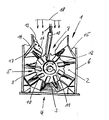
- the drawing shows a view into a metering device 1 with the end wall removed.
- the dosing device 1 consists essentially of a container 2 with the container side walls 6, which has a sieve 3 on its underside 4. Opposed to the sieve 3 are angled guide walls 14 and 15 which on the one hand come to rest on the side walls 6 and on the other hand form an inlet opening 7 and which run approximately at an angle of 45 ° tangentially to the circular cross section of the brush roller.
- the bulk material to be dosed is continuously filled into the inlet opening 7 in the direction of fall 18.
- a brush roller consisting essentially of one. on the end walls of the container 2 rotatably mounted shaft 8, on which rotatably connected to the shaft 8 brush holder 11 are arranged, on which in the circumferential direction around the shaft 8 evenly distributed brush strips 10 with substantially radially directed bristles 9 arranged parallel to the shaft 8 and are attached.
- the brush roller 5 rotates during operation in the direction of arrow 12, so that the bulk material filled in through the inlet opening 7 is carried along by the bristles 9 and the brush strips 10 and placed on the sieve 3 of the container and by the bristles 9 which continue to run the sieve is passed through.
- a scraper 16 is fastened in parallel position to the shaft 8 on the inlet side 13 of the guide wall 14.
- the scraper edge of the scraper 16 which is also parallel to the shaft 8, simply scrapes off excess bulk material, so that the chambers formed by the brush strips 10 and the bristles 9 arranged thereon then pass through the scraper 16 and its scraper edge 17 in the direction of rotation always have the same level. Since it is now possible to ensure constant overfilling due to the effect of the scraper 16, the risk of underfilling is also eliminated.
- the brush strips 10 can be removed from the brush strip carriers 11 of the brush roller 5 and turned or exchanged for other brush strips, for example with different bristles 9 or a different length of the bristles 9.
- the metering device 1 can be set up for different bulk goods or different bulk goods quality, or worn bristle strips can be exchanged very simply.
- the scraper 16 can be arranged movably on the guide wall 14 so that the position of the scraper edge 17 can be changed.
- the entire dosing device 1 described is part of an overall system for coating any surfaces, For example, for coating carpets, wallpapers or other surfaces, with rod-shaped bulk material, preferably with so-called flock, in which the rod-shaped bulk material is aligned after being passed through the sieve 3 of the metering device 1 in an electrostatic field and processed further in this aligned state.
- the use of the scraper 16 according to the invention considerably improves the metering accuracy of the metering device 1 and simplifies the monitoring effort of the overall system.
- the devices for filling the dosing device 1 with bulk material can be made simpler because it is now not necessary to ensure that the exact same amount of bulk material is filled in as the sieve 3 leaves below.
- the use of the scraper 16 according to the invention is therefore associated with considerable advantages.
Abstract
Description
Die Erfindung betrifft eine Dosiereinrichtung mit einem Behälter mit einem auf der Unterseite angeordneten Sieb zum Durchlaß von in Form von stäbchenförmigem Schüttgut anfallenden Flock und einer innerhalb des Behälters über dessen ganze Breite angeordneten Bürstenwalze, im wesentlichen bestehend aus einer drehantreibbar im Behälter über an den beiden Enden über je in einer Behälterstirnwand angeordneten Lageraugen gelagerten Welle und mehreren in Umfangsrichtung gleichmäßig verteilt angeordneten und im wesentlichen radial gerichteten Borsten tragenden Bürstenleisten, welche von mehreren in für eine Abstützung der Bürstenleisten auf der Welle geeigneten Verteilung drehfest angeordneten Bürstenleistenträgern gehalten werden und einer dem Sieb im Behälter gegenüberliegend angeordneten und von Leitwänden mit nach oben geöffneten Bereichen gebildeten Einlauföffnung für das Schüttgut.The invention relates to a dosing device with a container with a sieve arranged on the underside for the passage of flock in the form of rod-shaped bulk material and a brush roller arranged within the container over its entire width, consisting essentially of a rotatably drivable in the container at both ends Via a shaft mounted in each of the container end walls and a plurality of brush strips arranged evenly distributed in the circumferential direction and carrying substantially radially directed bristles, which are held by several brush strip carriers arranged in a rotationally fixed manner for supporting the brush strips on the shaft, and one in the sieve in the container oppositely arranged and formed by guide walls with upwardly open areas for the bulk material.
Dosiereinrichtungen der oben beschriebenen Art sind der Anmelderin aus der eigenen Produktion bekannt. Bei solchen Dosiereinrichtungen wird das stäbchenförmige Schüttgut, beispielsweise Flock, von oben in den Behälter der Dosiereinrichtung kontinuierlich hineingeschüttet, während sich die im Behälter angeordnete Bürstenwalze dreht. Die von den Bürstenleisten mit den darauf angeordneten Borsten auf der Bürstenwalze gebildeten Kammern werden hierbei während ihres Vorbeilaufs an der Einfüllöffnung mit Schüttgut gefüllt, welches sie später auf dem der Einlauföffnung gegenüberliegend am Behälter angeordneten Sieb ablegen und mit den Borsten der Bürstenleisten durch das Sieb hindurch streichen. Dies muß mit großer Gleichmäßigkeit geschehen, damit die Beschichtungsdichte des mit dem Schüttgut zu beschichtenden Gegenstandes die gewünschte Gleichmäßigkeit aufweist. Eine Einflußgröße hierbei ist der Gewichtsdruck des Schüttgutes auf das Sieb des Behälters. Um diesen Schüttdruck möglichst gleichmäßig zu halten, trachtet man im Stand der Technik danach, das Schüttgut entsprechend gleichmäßig in die Einlaßöffnung des Behälters einzugeben. Dies aber führt immer wieder zu Schwierigkeiten, so daß sich entweder ein zu geringes oder ein zu großes Schüttgewicht in ständigem Wechsel mit den entsprechend negativen Auswirkungen auf die Abrieseldichte ergibt.Dosing devices of the type described above are known to the applicant from its own production. In such metering devices, the rod-shaped bulk material, for example flock, is continuously poured into the container of the metering device from above while the brush roller arranged in the container rotates. The chambers formed by the brush strips with the bristles arranged on them on the brush roller are filled with bulk material as they pass the filling opening, which they later place on the sieve arranged opposite the inlet opening and sweep through the sieve with the bristles of the brush strips . This must be done with great uniformity so that the coating density of the object to be coated with the bulk material has the desired uniformity. One factor influencing this is the weight pressure of the bulk material on the sieve of the container. In order to keep this bulk pressure as uniform as possible, the prior art seeks to enter the bulk material evenly into the inlet opening of the container. However, this always leads to difficulties, so that either too low or too large bulk density results in constant alternation with the corresponding negative effects on the drainage density.
Der Erfindung liegt daher die Aufgabe zugrunde, eine Dosiereinrichtung vorzuschlagen, mit der das Schüttgewicht des Schüttgutes, das auf dem Sieb abgelegt wird, gleichmäßig gehalten werden kann.The invention is therefore based on the object of proposing a metering device with which the bulk weight of the bulk material which is deposited on the sieve can be kept uniform.
Diese Aufgabe wird erfindungsgemäß bei einer Dosiereinrichtung der eingangs beschriebenen Art dadurch gelöst, daß an der an der Einlaufseite der Bürstenleisten von der Einlauföffnung in den Behälter liegenden Leitwand ein Abstreifer vorgesehen ist mit parallel zur Welle liegender Abstreifkante zum Abstreifen von überschüssigem Schüttgut. Dieser Abstreifer sorgt dafür, daß der Füllungszustand der einzelnen von den die Borsten tragenden Bürstenleisten gebildeten Kammer immer gleichmäßig ist und in seiner Größe von der Lage der Abstreifkante abhängig ist. Durch das Vorhandensein des Abstreifers ist es möglich, Schüttgut in stets zu großer Menge zuzugeben, da das überschüssige Schüttgut stets vom Abstreifer abgestreift wird, so daß dennoch ein gleichmäßiger Füllungsstand erreicht wird. Gleichzeitig wird hierdurch eine Unterfüllung verhindert.This object is achieved in a metering device of the type described above in that a wiper is provided on the inlet side of the brush strips from the inlet opening into the container with a scraper lying parallel to the shaft for wiping off excess bulk material. This scraper ensures that the filling state of the individual chamber formed by the brush strips carrying the bristles is always uniform and its size is dependent on the position of the scraper edge. The presence of the scraper makes it possible to always add large quantities of bulk material, since the excess bulk material is always stripped off by the scraper, so that a uniform filling level is nevertheless achieved. At the same time, this prevents underfilling.
Nach einer Ausgestaltung der Erfindung ist noch vorgeschlagen daß der Abstreifer mit mindestens einer Komponente senkrecht zum Sieb lageveränderlich angeordnet ist. Auf diese Art und Weise kann der Füllstand und das Füllgewicht den spezifischen Eigenschaften des Schüttgutes angepaßt werden.According to one embodiment of the invention, it is also proposed that the stripper is arranged with at least one component perpendicular to the sieve in a variable position. In this way, the fill level and the fill weight can be adapted to the specific properties of the bulk material.
Nach einer weiteren Ausgestaltung der Erfindung ist noch vorgeschlagen, daß mindestens die Leitwand, an der der Abstreifer angeordnet ist, tangential zum Kreisquerschnitt der Bürstenwalze und ungefähr unter einem Winkel von 45° im Behälter angeordnet ist. Hierdurch wird eine besonders vorteilhafte Lage des Abstreifers und eine noch gleichmäßigere Füllung aller Kammern erreicht.According to a further embodiment of the invention proposed that at least the guide wall, on which the scraper is arranged, is arranged tangentially to the circular cross section of the brush roller and approximately at an angle of 45 ° in the container. In this way, a particularly advantageous position of the scraper and an even more uniform filling of all chambers is achieved.
Die Erfindung soll nun anhand der beigefügten Zeichnung, die ein Ausführungsbeispiel darstellt, näher erläutert werden.The invention will now be explained in more detail with reference to the accompanying drawing, which represents an embodiment.
Die Zeichnung zeigt einen Blick in eine Dosiereinrichtung 1 bei abgenommener Stirnwand. Die Dosiereinrichtung 1 besteht im wesentlichen aus einem Behälter 2 mit den Behälterseitenwänden 6, der auf seiner Unterseite 4 ein Sieb 3 aufweist. Dem Sieb 3 gegenüberliegend sind abgewinkelte Leitwände 14 und 15 angeordnet, die einerseits an den Seitenwänden 6 zur Anlage kommen und andererseits eine Einlauföffnung 7 bilden und die etwa unter einem Winkel von 45° tangential zum Kreisquerschnitt der Bürstenwalze verlaufen. In diese Einlauföffnung 7 wird das zu dosierende Schüttgut in Fallrichtung 18 kontinuierlich eingefüllt.The drawing shows a view into a metering device 1 with the end wall removed. The dosing device 1 consists essentially of a
Im Inneren des Behälters 2 befindet sich eine Bürstenwalze, im wesentlichen bestehend aus einer. an den Stirnwänden des Behälters 2 drehantreibbar gelagerten Welle 8, auf welcher drehfest mit der Welle 8 verbunden Bürstenleistenträger 11 angeordnet sind, auf denen in Umfangsrichtung um die Welle 8 herum gleichmäßig verteilt Bürstenleisten 10 mit im wesentlichen radial gerichteten Borsten 9 parallel zur Welle 8 angeordnet und befestigt sind.Inside the
Die Bürstenwalze 5 dreht während des Betriebes in Richtung des Pfeiles 12, so daß das durch die Einlauföffnung 7 eingefüllte Schüttgut von den Borsten 9 und den Bürstenleisten 10 mitgenommen und auf dem Sieb 3 des Behälters abgelegt und von den weiterlaufenden Borsten 9 durch das Sieb hindurchgestrichen wird.The
Zur Vermeidung einer Unterfüllung mit den dazugehörigen negativen Auswirkungen muß die kontinuierlich einfließende Schüttgutmenge in ihrem Massestrom ständig kontrolliert werden, damit außer der Unterfüllung auch eine Überfüllung mit ebenfalls - negativen Auswirkungen vermieden wird. Um diese ständige Beobachtung und aufwendige Regelung des Massestromes des Schüttgutes zu vermeiden, ist an der Einlaufseite 13 der Leitwand 14 ein Abstreifer 16 in paralleler Lage zur Welle 8 befestigt. Die Abstreifkante des Abstreifers 16, die ebenfalls parallel zur Welle 8 liegt, streift überschüssig eingefülltes Schüttgut einfach ab, so daß dann die von den Bürstenleisten 10 und den darauf angeordneten Borsten 9 gebildeten Kammern, wenn sie in Drehrichtung den Abstreifer 16 und dessen Abstreifkante 17 passiert haben, immer gleichen Füllstand aufweisen. Da man nun infolge der Wirkung des Abstreifers 16 bedenkenlos für eine ständige Überfüllung sorgen kann, ist damit auch die Gefahr der Unterfüllung beseitigt.In order to avoid underfilling with the associated negative effects, the mass flow rate of the continuously flowing bulk material must be constantly checked so that overfilling with negative effects is also avoided. In order to avoid this constant observation and complex regulation of the mass flow of the bulk material, a
Wie in der Zeichnung im Bereich der Einlaßöffnung dargestellt, können die Bürstenleisten 10 aus den Bürstenleistenträgern 11 der Bürstenwalze 5 entnommen und gewendet oder gegen andere Bürstenleisten, beispielsweise mit anderen Borsten 9 oder anderer Länge der Borsten 9, ausgetauscht werden. Hierdurch kann die Dosiereinrichtung 1 auf unterschiedliches Schüttgut oder unterschiedliche Schüttgutqualität eingerichtet werden oder es können ganz einfach verschlissene Borstenleisten ausgetauscht werden. Um sich den hierdurch entstehenden veränderten Verhältnissen in der Dosiereinrichtung 1 anpassen zu können, kann der Abstreifer 16 beweglich an der Leitwand 14 angeordnet sein, so daß die Lage der Abstreifkante 17 veränderbar ist.As shown in the drawing in the area of the inlet opening, the
Die gesamte beschriebene Dosiereinrichtung 1 ist Teil einer Gesamtanlage zur Beschichtung irgendwelcher Flächen, z.B. zur Beschichtung von Teppichen, Tapeten oder sonstigen Oberflächen, mit stäbchenförmigem Schüttgut, vorzugsweise mit sogenanntem Flock, bei dem das stäbenförmige Schüttgut nach dem Durchstreichen durch das Sieb 3 der Dosiereinrichtung 1 in einem elektrostatischen Feld ausgerichtet und in diesem ausgerichteten Zustand weiter verarbeitet wird. Die Anwendung des neuerungsgemäßen Abstreifers 16 verbessert erheblich die Dosiergenauigkeit der Dosiereinrichtung 1 und vereinfacht den Überwachungsaufwand der Gesamtanlage. Gleichzeitig können die Einrichtungen zur Auffüllung der Dosiereinrichtung 1 mit Schüttgut einfacher gestaltet werden, weil nun nicht darauf geachtet werden muß, daß präzise genausoviel Schüttgut eingefüllt wird, wie unten das Sieb 3 verläßt. Die Verwendung des erfindungsgemäßen Abstreifers 16 ist also mit erheblichen Vorteilen verbunden.The entire dosing device 1 described is part of an overall system for coating any surfaces, For example, for coating carpets, wallpapers or other surfaces, with rod-shaped bulk material, preferably with so-called flock, in which the rod-shaped bulk material is aligned after being passed through the
- 1 Dosiereinrichtung1 dosing device
- 2 Behälter2 containers
- 3 Sieb3 sieve
- 4 Unterseite4 bottom
- 5 Bürstenwalze5 brush roller
- 6 Behälterseitenwand6 container side wall
- 7 Einlauföffnung7 inlet opening
- 8 Welle8 wave
- 9 Borsten9 bristles
- 10 Bürstenleiste10 brush strip
- 11 Bürstenleistenträger11 brush strip holders
- 12 Drehrichtung12 direction of rotation
- 13 Einlaufseite13 inlet side
- 14 Leitwand14 guide wall
- 15 Leitwand15 guide wall
- 16 Abstreifer16 wipers
- 17 Abstreifkante17 scraper edge
- 18 Fallrichtung für Schüttgut18 Fall direction for bulk goods
Claims (3)
Priority Applications (1)
| Application Number | Priority Date | Filing Date | Title |
|---|---|---|---|
| AT83102760T ATE28805T1 (en) | 1982-05-28 | 1983-03-21 | DOSING DEVICE. |
Applications Claiming Priority (2)
| Application Number | Priority Date | Filing Date | Title |
|---|---|---|---|
| DE8215591U | 1982-05-28 | ||
| DE8215591 | 1982-05-28 |
Publications (3)
| Publication Number | Publication Date |
|---|---|
| EP0095566A2 true EP0095566A2 (en) | 1983-12-07 |
| EP0095566A3 EP0095566A3 (en) | 1985-05-22 |
| EP0095566B1 EP0095566B1 (en) | 1987-08-12 |
Family
ID=6740569
Family Applications (1)
| Application Number | Title | Priority Date | Filing Date |
|---|---|---|---|
| EP83102760A Expired EP0095566B1 (en) | 1982-05-28 | 1983-03-21 | Dosing device |
Country Status (3)
| Country | Link |
|---|---|
| EP (1) | EP0095566B1 (en) |
| AT (1) | ATE28805T1 (en) |
| DE (1) | DE3372935D1 (en) |
Cited By (1)
| Publication number | Priority date | Publication date | Assignee | Title |
|---|---|---|---|---|
| CN111001575A (en) * | 2019-12-31 | 2020-04-14 | 安徽盛源农产品购销股份有限公司 | Screening device for garlic slice processing pretreatment |
Citations (8)
| Publication number | Priority date | Publication date | Assignee | Title |
|---|---|---|---|---|
| US2293871A (en) * | 1940-12-14 | 1942-08-25 | Edwin J Fithian | Pneumatic feeder |
| US2573952A (en) * | 1948-07-29 | 1951-11-06 | Thomas O Bretherton | Apparatus for depositing strips of adhesive upon a base material |
| FR1096934A (en) * | 1953-01-28 | 1955-06-28 | Saladin & Co | Method and devices for applying bodies to supports under the action of force fields produced between these bodies and these supports |
| FR1130301A (en) * | 1954-08-22 | 1957-02-04 | Svenska Flaektfabriken Ab | Valve for grain materials |
| DE1013575B (en) * | 1954-09-15 | 1957-08-08 | Edmond Harvengt | Device for distributing or dispensing solid, loose material by means of a rotary slide valve preferably designed as a cell drum |
| GB1142039A (en) * | 1965-12-29 | 1969-02-05 | Besnier Flotex | Method and apparatus for the distribution of fibers |
| DE2740261A1 (en) * | 1977-09-07 | 1979-03-15 | Joachim Mueller | Material covering flocking applicator - has chamber with base and sieve frame matching rotary metering brush radius |
| FR2492788A1 (en) * | 1980-10-24 | 1982-04-30 | Batithermic | Bulk granular material distributor - has rotary feeder below hopper with pneumatic conveying system and flow control |
-
1983
- 1983-03-21 AT AT83102760T patent/ATE28805T1/en not_active IP Right Cessation
- 1983-03-21 DE DE8383102760T patent/DE3372935D1/en not_active Expired
- 1983-03-21 EP EP83102760A patent/EP0095566B1/en not_active Expired
Patent Citations (8)
| Publication number | Priority date | Publication date | Assignee | Title |
|---|---|---|---|---|
| US2293871A (en) * | 1940-12-14 | 1942-08-25 | Edwin J Fithian | Pneumatic feeder |
| US2573952A (en) * | 1948-07-29 | 1951-11-06 | Thomas O Bretherton | Apparatus for depositing strips of adhesive upon a base material |
| FR1096934A (en) * | 1953-01-28 | 1955-06-28 | Saladin & Co | Method and devices for applying bodies to supports under the action of force fields produced between these bodies and these supports |
| FR1130301A (en) * | 1954-08-22 | 1957-02-04 | Svenska Flaektfabriken Ab | Valve for grain materials |
| DE1013575B (en) * | 1954-09-15 | 1957-08-08 | Edmond Harvengt | Device for distributing or dispensing solid, loose material by means of a rotary slide valve preferably designed as a cell drum |
| GB1142039A (en) * | 1965-12-29 | 1969-02-05 | Besnier Flotex | Method and apparatus for the distribution of fibers |
| DE2740261A1 (en) * | 1977-09-07 | 1979-03-15 | Joachim Mueller | Material covering flocking applicator - has chamber with base and sieve frame matching rotary metering brush radius |
| FR2492788A1 (en) * | 1980-10-24 | 1982-04-30 | Batithermic | Bulk granular material distributor - has rotary feeder below hopper with pneumatic conveying system and flow control |
Cited By (2)
| Publication number | Priority date | Publication date | Assignee | Title |
|---|---|---|---|---|
| CN111001575A (en) * | 2019-12-31 | 2020-04-14 | 安徽盛源农产品购销股份有限公司 | Screening device for garlic slice processing pretreatment |
| CN111001575B (en) * | 2019-12-31 | 2021-04-02 | 安徽盛源农产品购销股份有限公司 | Screening device for garlic slice processing pretreatment |
Also Published As
| Publication number | Publication date |
|---|---|
| EP0095566B1 (en) | 1987-08-12 |
| DE3372935D1 (en) | 1987-09-17 |
| EP0095566A3 (en) | 1985-05-22 |
| ATE28805T1 (en) | 1987-08-15 |
Similar Documents
| Publication | Publication Date | Title |
|---|---|---|
| DE1652402B2 (en) | Device for coating a moving material web with a liquid | |
| DE2620399B2 (en) | Device for electrostatic spraying | |
| DE2434140C3 (en) | Device for coating food with an edible layer | |
| EP0065656A2 (en) | Apparatus for spray treatment, especially for spray painting objects | |
| DE1577658B2 (en) | METHOD AND DEVICE FOR EVEN DISTRIBUTION OF NATURAL OR ARTIFICIAL FIBERS FOR ELECTROSTATIC FLOCKING | |
| CH680726A5 (en) | Cleaning device for surface of conveyor belts - has interchangeable brush rollers for different cleaning actions | |
| DE2738894C2 (en) | Device for applying a coating mass to objects | |
| EP0095566B1 (en) | Dosing device | |
| DE2507025B2 (en) | Seed drill | |
| DE2649046C2 (en) | Compressed air spraying machine for concrete, mortar, etc. with a dosing device | |
| DE3227192A1 (en) | Rotary-driven cleaning brush for the conveyor belt of coating and spraying systems or the like | |
| DE8215591U1 (en) | Dosing device | |
| DE1962456C3 (en) | Powder application device | |
| DE3134968C2 (en) | Device for applying a protective layer on the inside of the weld or solder seam of can bodies | |
| EP0155293B1 (en) | Device for applying a material to a medium | |
| DE2950923C2 (en) | Device for the continuous application of a pulpy mixture on flat molds for the production of cement-bonded chipboard | |
| EP0120482B1 (en) | Device for applying a layer of fine ceramic material to a carrier | |
| DE3813109C1 (en) | ||
| DE3016832A1 (en) | DOSING DEVICE FOR GRAINY AND POWDERED GOODS | |
| DE2526953C3 (en) | Spreading and dosing device for fertilizers, seeds and other spreadable substances | |
| DE1577658C3 (en) | Method and device for the even distribution of natural or artificial fibers for electrostatic flocking | |
| DE1548938C (en) | Distribution and dosing device for granular or powdery products | |
| EP0370058B1 (en) | Device for sprinkling pieces of dough | |
| DE2009510A1 (en) | Silo discharge device | |
| EP0121581B1 (en) | Process for diminishing flock balls with low waste, and dosing device therefor |
Legal Events
| Date | Code | Title | Description |
|---|---|---|---|
| PUAI | Public reference made under article 153(3) epc to a published international application that has entered the european phase |
Free format text: ORIGINAL CODE: 0009012 |
|
| 17P | Request for examination filed |
Effective date: 19830411 |
|
| AK | Designated contracting states |
Designated state(s): AT BE CH DE FR GB IT LI NL SE |
|
| PUAL | Search report despatched |
Free format text: ORIGINAL CODE: 0009013 |
|
| AK | Designated contracting states |
Designated state(s): AT BE CH DE FR GB IT LI NL SE |
|
| 17Q | First examination report despatched |
Effective date: 19860122 |
|
| D17Q | First examination report despatched (deleted) | ||
| ITF | It: translation for a ep patent filed |
Owner name: SPADINI MARUSCO |
|
| GRAA | (expected) grant |
Free format text: ORIGINAL CODE: 0009210 |
|
| AK | Designated contracting states |
Kind code of ref document: B1 Designated state(s): AT BE CH DE FR GB IT LI NL SE |
|
| REF | Corresponds to: |
Ref document number: 28805 Country of ref document: AT Date of ref document: 19870815 Kind code of ref document: T |
|
| REF | Corresponds to: |
Ref document number: 3372935 Country of ref document: DE Date of ref document: 19870917 |
|
| ET | Fr: translation filed | ||
| PLBE | No opposition filed within time limit |
Free format text: ORIGINAL CODE: 0009261 |
|
| STAA | Information on the status of an ep patent application or granted ep patent |
Free format text: STATUS: NO OPPOSITION FILED WITHIN TIME LIMIT |
|
| 26N | No opposition filed | ||
| PGFP | Annual fee paid to national office [announced via postgrant information from national office to epo] |
Ref country code: SE Payment date: 19910220 Year of fee payment: 9 |
|
| PGFP | Annual fee paid to national office [announced via postgrant information from national office to epo] |
Ref country code: BE Payment date: 19910305 Year of fee payment: 9 |
|
| PGFP | Annual fee paid to national office [announced via postgrant information from national office to epo] |
Ref country code: AT Payment date: 19910326 Year of fee payment: 9 |
|
| PGFP | Annual fee paid to national office [announced via postgrant information from national office to epo] |
Ref country code: NL Payment date: 19910331 Year of fee payment: 9 |
|
| PGFP | Annual fee paid to national office [announced via postgrant information from national office to epo] |
Ref country code: CH Payment date: 19910402 Year of fee payment: 9 |
|
| PG25 | Lapsed in a contracting state [announced via postgrant information from national office to epo] |
Ref country code: AT Effective date: 19920321 |
|
| PG25 | Lapsed in a contracting state [announced via postgrant information from national office to epo] |
Ref country code: SE Effective date: 19920322 |
|
| PG25 | Lapsed in a contracting state [announced via postgrant information from national office to epo] |
Ref country code: LI Effective date: 19920331 Ref country code: CH Effective date: 19920331 Ref country code: BE Effective date: 19920331 |
|
| BERE | Be: lapsed |
Owner name: ESCH HELMUT Effective date: 19920331 |
|
| PG25 | Lapsed in a contracting state [announced via postgrant information from national office to epo] |
Ref country code: NL Effective date: 19921001 |
|
| NLV4 | Nl: lapsed or anulled due to non-payment of the annual fee | ||
| REG | Reference to a national code |
Ref country code: CH Ref legal event code: PL |
|
| EUG | Se: european patent has lapsed |
Ref document number: 83102760.2 Effective date: 19921005 |
|
| ITTA | It: last paid annual fee | ||
| REG | Reference to a national code |
Ref country code: GB Ref legal event code: 732E |
|
| REG | Reference to a national code |
Ref country code: FR Ref legal event code: TP |
|
| PGFP | Annual fee paid to national office [announced via postgrant information from national office to epo] |
Ref country code: GB Payment date: 20000218 Year of fee payment: 18 |
|
| PGFP | Annual fee paid to national office [announced via postgrant information from national office to epo] |
Ref country code: FR Payment date: 20000316 Year of fee payment: 18 |
|
| PGFP | Annual fee paid to national office [announced via postgrant information from national office to epo] |
Ref country code: DE Payment date: 20000426 Year of fee payment: 18 |
|
| PG25 | Lapsed in a contracting state [announced via postgrant information from national office to epo] |
Ref country code: GB Free format text: LAPSE BECAUSE OF NON-PAYMENT OF DUE FEES Effective date: 20010321 |
|
| GBPC | Gb: european patent ceased through non-payment of renewal fee |
Effective date: 20010321 |
|
| PG25 | Lapsed in a contracting state [announced via postgrant information from national office to epo] |
Ref country code: FR Free format text: LAPSE BECAUSE OF NON-PAYMENT OF DUE FEES Effective date: 20011130 |
|
| REG | Reference to a national code |
Ref country code: FR Ref legal event code: ST |
|
| PG25 | Lapsed in a contracting state [announced via postgrant information from national office to epo] |
Ref country code: DE Free format text: LAPSE BECAUSE OF NON-PAYMENT OF DUE FEES Effective date: 20020101 |