EP0095291A2 - Continuous measurement of the concentration of a predetermined ingredient in a diluted liquid - Google Patents
Continuous measurement of the concentration of a predetermined ingredient in a diluted liquid Download PDFInfo
- Publication number
- EP0095291A2 EP0095291A2 EP83302731A EP83302731A EP0095291A2 EP 0095291 A2 EP0095291 A2 EP 0095291A2 EP 83302731 A EP83302731 A EP 83302731A EP 83302731 A EP83302731 A EP 83302731A EP 0095291 A2 EP0095291 A2 EP 0095291A2
- Authority
- EP
- European Patent Office
- Prior art keywords
- liquid
- concentration
- dilution ratio
- mixed liquid
- change
- Prior art date
- Legal status (The legal status is an assumption and is not a legal conclusion. Google has not performed a legal analysis and makes no representation as to the accuracy of the status listed.)
- Granted
Links
Images


Classifications
-
- A—HUMAN NECESSITIES
- A61—MEDICAL OR VETERINARY SCIENCE; HYGIENE
- A61M—DEVICES FOR INTRODUCING MEDIA INTO, OR ONTO, THE BODY; DEVICES FOR TRANSDUCING BODY MEDIA OR FOR TAKING MEDIA FROM THE BODY; DEVICES FOR PRODUCING OR ENDING SLEEP OR STUPOR
- A61M1/00—Suction or pumping devices for medical purposes; Devices for carrying-off, for treatment of, or for carrying-over, body-liquids; Drainage systems
- A61M1/36—Other treatment of blood in a by-pass of the natural circulatory system, e.g. temperature adaptation, irradiation ; Extra-corporeal blood circuits
- A61M1/3672—Means preventing coagulation
Definitions
- the present invention relates to continuous measurement of the concentration of a predetermined ingredient in a diluted liquid. More particularly the present invention relates to continuous monitoring of the concentration of the predetermined ingredient in a liquid which is mixed with a diluent to obtain the diluted liquid.
- a tube pump that is of few pulsations and of little dead volume and is able to continuously feeding a very small quantity of liquid.
- a tube pump that is of few pulsations and of little dead volume and is able to continuously feeding a very small quantity of liquid.
- a tube pump has the defect of changing in quantity of discharge with the passage of time and further of fluctuating in dilution ratio in the course of continuing with the measurement for many hours: therefore it is hard to obtain accurately the measured value. This is attributable for example, to the deterioration or deformation with the passage of time of the pump tubes which are continuously squeezed, or to the change in inner diameter of the tubes due to the adhesion of the constituents of the liquid.
- the way of compensating the dilution ratio at the time of continuously blood-drawing which is prevalent heretobefore has such defects that it causes pain and danger of contagion to the patient, that it requires many hands, and that the operation of it is very complicated, involving the possibility of the occurrence of errors attributable to mistakes in operating.
- Another object of this invention is to provide a method and an apparatus by and on which the compensating motion can be automated, the compensation of the dilution ratio can be done automatically at periods prescribed in advance, and the measurement of high accuracy can be performed continuously, and, in addition, to provide also a method in which the compensation of the dilution ratio by the reference liquid to be conducted before the commencement of the measurement is dispensable, or the compensation of the dilution ratio can be made even by using a reference liquid whose concentration is unknown.
- a further object of this invention is to provide an apparatus which has the ability to compensate (recheck) the dilution ratio while it is still in a state of loading the double-current catheter on the human body (patient) and without the necessity of any human- power operation.
- the invention provides a method and also an apparatus for continuously measuring a specified ingredient contained in a liquid to be tested, particularly, wherein the accurate measurement of concentration may be performed by compensating the dilution ratio as occasion calls at the time of the continuous measurement of the liquid to be tested in its state diluted by a diluent while using a tube pump as a liquid-feeding means.
- the invention is described below with reference to continuous measurement of blood-sugar value (glucose concentration) in blood sampled by using a double-current catheter.
- the apparatus comprises a double-current catheter 1, catheter tubes 11 and 12, tube pumps 2 and 3, first and second pulse motors 4 and 5 for driving the tube pumps 2 and 3 respectively, a measuring section 6, a microcomputer 7, and an indicating device 71.
- Pulse motor-driving circuits 41 and 51 are connected to the first and second motors 4 and 5 respectively.
- Arrows 72 and 73 denote controlling signals (speed change-command signals) which are emitted from the microcomputer 7. In accordance with these signals 72 and 73 the number of revolutions (speed) of the tube pumps 2 and 3 can be changed optionally.
- the tube pumps 2 and 3 comprise rotors 21 and 31 respectively, rotor shafts 32 and 33, rollers 23 and 33, pump heads 24 and 34, and pump tubes 25 and 35.
- the double-current catheter 1 is inserted into the inside of a canula la whose tip is to be detained in a vein.
- the gap between the catheter 1 and the canula la forms an anticoagulant reservoir 13.
- Anticoagulant 9 is supplied through an anticoagulant- > feeding tube 92 and a first catheter tube 11 into the anticoagulant reservoir 13 by the feeding action of the first tube pump 2.
- An air-introducing needle 93 is provided.
- a blood sample (liquid to be tested 8 is drawn in, at the tip part of a suction tube 14 of the catheter by the sucking action of the second tube pump 3 while being mixed with (and diluted by) the anticoagulant 9, forming a mixed liquid 10.
- the mixed liquid 10 passes through the suction tube 14 of the catheter, the second catheter tube 12, and a mixed liquid-feeding tube 82, and reaches the measuring section 6.
- a measuring signal 61 corresponding to the glucose concentration in the mixed liquid 10 is emitted from, for example, an immobilized enzyme film electrode.
- the measuring signal 61 is put into an arithmetic memory system of the microcomputer from which the blood-sugar value is calculated on the basis of the operation described below. This value is displayed on the indicating device 71.
- the dilution ratio cf is the ratio by volume of the mixed liquid 10 to the blood sample 8.
- the dilution ratio o also is equal to the ratio of the blood-sugar value X in the blood sample 8 and also to the glucose concentration G in the mixed liquid 10 therefore:
- the blood-sugar value X means the glucose concentration in the blood sample and is to be distinguished from the glucose concentration G in the mixed liquid.
- the measuring signal 61 corresponding to this G is obtained, the value of J is operated being regarded as a definite one obtained ahead of time and is displayed on the indicating device as X.
- the fluctuating portion of the value ⁇ is expressed so much as it is as errors.
- a method in which the compensation of the dilution ratio is done by using the reference liquid whose concentration is known or by using the blood sample drawn separately by the use of a syringe, as done in the conventional technique mentioned above, as a substitute for the blood sample continuously drawn.
- values of J given by the equation (1) are successively stored in the microcomputer 7.
- the values of J may be stored by various methods, such as by manually inputting or automatically memorizing the values obtained by using a reference liquid whose concentration is known in place of the blood sample 8, otherwise the real value of the dilution ratio in the process of the measurement as described later.
- the double-current catheter 1 is set in a vein of the patient in order to commence the measurement.
- the method described below in accordance with the invention comprises finding real dilution ratios at any point of time, making the microcomputer 7 correctively memorize the above real dilution ratios in succession, and obtaining continuously accurate blood-sugar values Xs, on the basis of the following principle:
- the quantity of discharge of the tube pump 2 becomes also N times because the number of revolution of the pump and its quantity of discharge stand in proportional relation each to other.
- the glucose concentration in the mixed liquid 10 under the above condition is G 1
- the blood-sugar value of the blood sample 8 is X
- the quantities of discharge of the tube pumps 2 and 3 are QH 1 ' and QB 1 ', respectively
- the real dilution ratio is ⁇ 1 '
- X 1 and X 1 ' are substantially equal in light of the characteristic of the change with the passage of time of the blood-sugar value, and similarly the degrees of deformation of the pump tubes 25 and 35 or the change of inner diameter thereof are negligible, so that QB 1 and QB 1 ' as well as QH 1 and QH 1 ' can be regarded as equal, respectively, wherefrom the real dilution ratio is permissible to be decided by eliminating the quantities of flow of the tube pumps from equations (3) and (4).
- the number of revolution of the tube pump 2 is forcedly altered similarly to the above to obtain ⁇ 2 , ⁇ 3 whil which are correctively stored in succession.
- the number of revolution of the tube pump 2 may at each period of time be increased by N times temporarily at each period of time and immediately be restored to the original state (that is, reduced to 1 / N ), or after the measurement is done keeping the state of increasing the number of revolution N times at the period of time T 1 intact, is increased by 1 / N time at the period of time T 2'
- the dilution ratio may be stored in the microcomputer 7 by various methods, for example, by inputting manually numerical values displayed (coming out) on the indicating window 75 of the operating section 74 by using the input key 76, or by automatically storing them by operating a dilution ratio-compensating switch 77.
- the number of revolutions of the tube pump 2 on the anticoagulant-feeding side is increased forcedly by N times in order find the respective glucose concentration values (G 1 , G 1 ') in the two kinds of mixed liquids
- the number of revolution of the said pump 2 is increased by 1/N time, or the tube pump 3 on the mixed liquid side is changed in speed or both tube pumps 2 and 3 are changed in speed alternately or simultaneously.
- this compensation (recheck) of the dilution ratio is manually instructed to the apparatus at any period of time.
- the microcomputer 7 may be set so as to be conducted automatically the compensation of the dilution ratio, for example, after 30 minutes, after 60 minutes and so on.
- the real dilution ratio was found by the first speed-change operation, it suffices if the real dilution ratio is decided on the average of the values of all dilution ratios obtained by repeating such speed-change operations as above several times at a certain period of time, (in this case, it is permissible to apply the combination of various kinds of speed-change operations mentioned above instead).
- the value of the blood sugar in the blood sample is arranged so as to be calculated by using the real dilution ratio obtained at the then period of time under the speed change operation of the tube pump until the next time as it is. This calculation can be also done in such a manner as follows:
- the driving source of the tube pumps 2 and 3 is not limited only to pulse motors, but it will do if it is anything that is provided with the function able to obtain a desired number of revolution, including the case where some speed-change gear is employed.
- a double-current catheter 100 which is designed and arranged so as to also perform the duties of both the pump tube 25 and anticoagulant-feeding tube 92 and the tube 35 and mixed liquid-feeding tube 82 in the former example, by making each of the catheter tubes 11 and 12 longer, as shown in Figure 3.
- Stoppers 15' are attached to the catheter tube 11 and 12. Stopper receivers 26 and 36 are provided in the tube pumps 2 and 3.
- the double-current catheter 100 has various advantages that it is subject to less sediment of foreign matter because of both its tubes 11 and 12 having no more than the end parts in their connecting points, that it has less apprehension of the tubes being clogged, that the exchange of the catheter is made very easily and promptly, that the damage of the contact places with roller attributable to the speed change of the pumps 2 and 3 offers no problem on exchangeable independently in each catheter, and so on.
- the method and apparatus according to the present invention may be used in the field of chemical analysis for continuously measuring specified ingredients, including the aforesaid analysis of blood.
- this method and apparatus is not limited to the case where the double-current catheter is used in the manner as mentioned above; it may be also applied to the case where the progression of the mixed liquids (C o ) which are supplied to the measuring section 6 is observed with the passage of time: one mixed liquid has been obtained by transferring the liquid to be tested (Sa) and the diluent (Di) by the respective tube pumps (P) while mixing on the way, as shown in Figure 4(a), and another mixed liquid by send the liquid to be tested (Sa) and the diluent (Di) by the respective pumps (P) into the mixing vessel (C) while stirring thereat.
- the compensating method of the dilution ratio according to the present invention is such a one in which, in the case of finding the concentration of a specified substance contained in the liquid to be tested through the measurement of ) the concentration of the mixed liquid which is made by mixing the liquid to be tested with the diluent by the use of two tube pumps, the real dilution ratio and therewith the accurate concentration are found easily and certainly by making forcedly the quantity of liquid-feeding of either or both of the tube pumps. Accordingly, even when such a measurement as the continuous measuring of the blood-sugar value is made for long hours, it becomes possible to perform the compensation (recheck) of the dilution ratio in a state of loading the double-current catheter on the patient as it is.
- this catheter provides a technique of very high utility in the clinical field. Further, this invention is able to automate the compensating motion and to perform the automatic compensation of the dilution ratio at the present period, so that it has become possible for the analyser and the technician to make the measurement of high accuracy continuously though staying away remote from the place where the measuring apparatus is set up, thereby a large economy of time and labour can be brought about.
- the apparatus of our invention it is also possible to eliminate various kinds of adverse influences such as, for example, by the deterioration and deformation of the tube pumps with the passage of time, or the change in inner diameter of the tubes similarly with the passage of time, and consequently the apparatus is suitable for long use, with the result that the total cost of the measuring operation be decreased.
- the reference liquid to be used for the compensation of the dilution ratio which will be performed prior to the commencement of the measurement must have a known concentration; it suffices if only it is adjusted nearly to a desired concentration. That is, it becomes possible to use a reference liquid of unknown concentration by making the compensation of the dilution ratio according to the present invention.
- the invention is very convenient in the points that the reference liquid can be used as it is even in the case of being ambiguous as to whether it has such an accurate concentration as prescribed or not, and that there can be used a sterilized reference liquid which is adjustable easily by using e.g. physiological saltwater or glucose injection commercially available on the market.
Abstract
Description
- The present invention relates to continuous measurement of the concentration of a predetermined ingredient in a diluted liquid. More particularly the present invention relates to continuous monitoring of the concentration of the predetermined ingredient in a liquid which is mixed with a diluent to obtain the diluted liquid.
- It is connon when measuring the concentration of a specified ingredient (a substance to be measured) contained in a liquid to be tested, to supply to a measuring device instead of the single liquid to be tested, a mixture of the liquid to be tested and some other liquid (in other words, to supply the liquid to be tested diluted by some other liquid). The purpose of such mixing (dilution) may be, for example, to effect pH-adjustment, to remove interfering matters, to prevent coagulation in a blood sample or simply to dilute the liquid to be tested. The dilution of the liquid to be tested is liable to cause errors in the measured values of concentration owing to variations (errors or scattering) of the mixing rate (dilution ratio). In particular, when the liquid to be tested is flowing through a channel and is continuously sampled (picked) and its concentration is continuously monitored, there occurs often the difficulty of keeping the dilution ratio constant, fluctuations of the dilution ratio being directly expressed in errors of the measured value of concentration.
- To give an instance, in an apparatus wherein blood is drawn from a vein of the subject (patient) by the use of a double-current catheter while infusing an anticoagulant in order to continuously and automatically monitor the concentration of a specified ingredient (for example, glucose) contained in the blood, as a means for feeding liquid agent to the blood-drawing part is generally employed a tube pump that is of few pulsations and of little dead volume and is able to continuously feeding a very small quantity of liquid. However, such a pump has the defect of changing in quantity of discharge with the passage of time and further of fluctuating in dilution ratio in the course of continuing with the measurement for many hours: therefore it is hard to obtain accurately the measured value. This is attributable for example, to the deterioration or deformation with the passage of time of the pump tubes which are continuously squeezed, or to the change in inner diameter of the tubes due to the adhesion of the constituents of the liquid.
- With a view to avoiding such a vexed problem, there is heretofore adopted a method in which the double-current catheter is once detached from the patient in the middle course of the measurement, is made to suck in a reference liquid, and, after the dilution ratio is compensated, the catheter is reattached to the patient. When using this method, however, the measurement is not only discontinued for a while but also accompanied by troublesome operations, and besides due consideration must be paid to contagions accidents to the living body which might be contingent to such operations. In order to eliminate such weak points, there is disclosed in the Japanese Patent Application Disclosure No. 135795 of 1977 a technique in which the dilution ratio is compensated for by comparing the blood separately drawn from a vein of the patient by the use of a syringe with the blood sample drawn from the catheter. However, the separately blood-drawing by syringe not only causes pain to the patient but, what is worse, increases the quantity of blood loss, while on the other hand it is required for the blood sample drawn by syringe to be treated anticoagulantly within a prescribed short time, and to be diluted accurately to a prescribed value. Thus the way of dealing with it is very intricate.
- As mentioned above, the way of compensating the dilution ratio at the time of continuously blood-drawing which is prevalent heretobefore has such defects that it causes pain and danger of contagion to the patient, that it requires many hands, and that the operation of it is very complicated, involving the possibility of the occurrence of errors attributable to mistakes in operating.
- It is an object of this invention to eliminate such defects as mentioned above and to provide a method by which the measurement of concentration can be performed stably and accurately for many hours at the time of continuously measuring the liquid to be tested in a state of being diluted by a diluent, and, in addition, to provide also a method by which the accurate measurement of concentration can be performed by continuously diluting the liquid to be tested by using a tube pump and a double-current catheter at the same time.
- Another object of this invention is to provide a method and an apparatus by and on which the compensating motion can be automated, the compensation of the dilution ratio can be done automatically at periods prescribed in advance, and the measurement of high accuracy can be performed continuously, and, in addition, to provide also a method in which the compensation of the dilution ratio by the reference liquid to be conducted before the commencement of the measurement is dispensable, or the compensation of the dilution ratio can be made even by using a reference liquid whose concentration is unknown.
- A further object of this invention is to provide an apparatus which has the ability to compensate (recheck) the dilution ratio while it is still in a state of loading the double-current catheter on the human body (patient) and without the necessity of any human- power operation.
- These objects of this invention can be achieved through finding a real dilution ratio while conducting the forced changing of the quantities of liquid to be fed of either of or both of two tube pumps which each transfer either a liquid to be tested and a diluent or the mixture of the above two and a diluent.
- The invention provides a method and also an apparatus for continuously measuring a specified ingredient contained in a liquid to be tested, particularly, wherein the accurate measurement of concentration may be performed by compensating the dilution ratio as occasion calls at the time of the continuous measurement of the liquid to be tested in its state diluted by a diluent while using a tube pump as a liquid-feeding means.
-
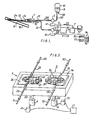
- Figure 1 is a schematic drawing showing an apparatus according to the invention;
- Figure 2 is a perspective view of a part of a tube pump of the apparatus;
- Figure 3 is a plan view showing a modification of the blood-drawing section; and
- Figure 4(a) and (b) are schematic drawings showing parts of apparatus according to the invention.
- The invention is described below with reference to continuous measurement of blood-sugar value (glucose concentration) in blood sampled by using a double-current catheter.
- The apparatus comprises a double-current catheter 1,
catheter tubes tube pumps second pulse motors 4 and 5 for driving thetube pumps measuring section 6, a microcomputer 7, and an indicatingdevice 71. Pulse motor-driving circuits second motors 4 and 5 respectively.Arrows signals tube pumps tube pumps rotors rotor shafts rollers pump heads pump tubes anticoagulant reservoir 13.Anticoagulant 9 is supplied through an anticoagulant- >feeding tube 92 and afirst catheter tube 11 into theanticoagulant reservoir 13 by the feeding action of thefirst tube pump 2. An air-introducingneedle 93 is provided. - A blood sample (liquid to be tested 8 is drawn in, at the tip part of a
suction tube 14 of the catheter by the sucking action of thesecond tube pump 3 while being mixed with (and diluted by) theanticoagulant 9, forming amixed liquid 10. The mixedliquid 10 passes through thesuction tube 14 of the catheter, thesecond catheter tube 12, and a mixed liquid-feeding tube 82, and reaches themeasuring section 6. In themeasuring section 6, ameasuring signal 61 corresponding to the glucose concentration in themixed liquid 10 is emitted from, for example, an immobilized enzyme film electrode. Themeasuring signal 61 is put into an arithmetic memory system of the microcomputer from which the blood-sugar value is calculated on the basis of the operation described below. This value is displayed on the indicatingdevice 71. - In this case, the dilution ratio cf is the ratio by volume of the
mixed liquid 10 to the blood sample 8. Supposing the quantity of discharge of thetube pump 2 is QH and that of thetube pump 3 is QB, the following equation can be obtained.
- Further, the dilution ratio o also is equal to the ratio of the blood-sugar value X in the blood sample 8 and also to the glucose concentration G in the
mixed liquid 10 therefore:
- (In the following, the blood-sugar value X means the glucose concentration in the blood sample and is to be distinguished from the glucose concentration G in the mixed liquid.)
- From the above two equations, the following equation, which gives blood-sugar value X, may be derived:

- Conventionally, when the
measuring signal 61 corresponding to this G is obtained, the value of J is operated being regarded as a definite one obtained ahead of time and is displayed on the indicating device as X. In such a case, possible fluctuations of the value of d are not taken into consideration, the fluctuating portion of the value δ is expressed so much as it is as errors. Aside from this, there is adopted a method in which the compensation of the dilution ratio is done by using the reference liquid whose concentration is known or by using the blood sample drawn separately by the use of a syringe, as done in the conventional technique mentioned above, as a substitute for the blood sample continuously drawn. - Contrary to this, in the present invention, values of J given by the equation (1) are successively stored in the microcomputer 7. The values of J may be stored by various methods, such as by manually inputting or automatically memorizing the values obtained by using a reference liquid whose concentration is known in place of the blood sample 8, otherwise the real value of the dilution ratio in the process of the measurement as described later.
- After the dilution ratio do obtained by using the reference liquid whose concentration is known is made to be stored in the microcomputer prior to the measurement, the double-current catheter 1 is set in a vein of the patient in order to commence the measurement.
- However, the above-mentioned QH and QB fluctuate with passage of time for the aforesaid reason, in proportion to which the value of S varies, too. Even if such a variation would be insignificant yet its errors can not be ignored when the measurement continues to be done for long hours.
- Hereupon, the method described below in accordance with the invention comprises finding real dilution ratios at any point of time, making the microcomputer 7 correctively memorize the above real dilution ratios in succession, and obtaining continuously accurate blood-sugar values Xs, on the basis of the following principle:
- First, supposing the blood-sugar value of the blood sample 8 at one point of time T 1 is X1, the glucose concentration in the
mixed liquid 10 is G1, the quantities of discharge of thetube pumps 
- Then, if the speed of revolution of the
first tube pump 2 is increased forcedly by N times by modifying the controllingsignal 72, the quantity of discharge of thetube pump 2 becomes also N times because the number of revolution of the pump and its quantity of discharge stand in proportional relation each to other. Supposing the glucose concentration in themixed liquid 10 under the above condition is G 1, the blood-sugar value of the blood sample 8 is X , the quantities of discharge of thetube pumps 
- In the case of the interval of the measurement being short, X1 and X1' are substantially equal in light of the characteristic of the change with the passage of time of the blood-sugar value, and similarly the degrees of deformation of the
pump tubes - That is, from these relations and by the equations (3) and (4) will be obtained the following equation:

measuring device 71. - Then follows that at certain periods of time T2, T3 ... the number of revolution of the
tube pump 2 is forcedly altered similarly to the above to obtain δ2, δ3 ...... which are correctively stored in succession. In this connection, the number of revolution of thetube pump 2 may at each period of time be increased by N times temporarily at each period of time and immediately be restored to the original state (that is, reduced to 1 / N ), or after the measurement is done keeping the state of increasing the number of revolution N times at the period of time T1 intact, is increased by 1 / N time at the period of time T 2' - Therefore, even though the dilution ratio fluctuates owing to the variation with the passage of time of the quantity of discharge of each of the tube pumps 2 and 3 at the time of the measurement, yet the dilution ratios stored in the microcomputer 7 are compensated successively to a value very approximate to the real dilution ratio on all occasion, so that it is possible to make the measurement of the accurate blood-sugar value continuously. The dilution ratio may be stored in the microcomputer 7 by various methods, for example, by inputting manually numerical values displayed (coming out) on the indicating
window 75 of the operating section 74 by using theinput key 76, or by automatically storing them by operating a dilution ratio-compensatingswitch 77. - A preferred embodiment of the present invention has been described above with reference to the drawings. However, the invention is not limited thereto and various modifications such as described below may be made within the scope of the invention.
- Although, in the above-described example, the number of revolutions of the
tube pump 2 on the anticoagulant-feeding side is increased forcedly by N times in order find the respective glucose concentration values (G 1, G 1') in the two kinds of mixed liquids, it is equally satisfactory if the number of revolution of the saidpump 2 is increased by 1/N time, or thetube pump 3 on the mixed liquid side is changed in speed or both tube pumps 2 and 3 are changed in speed alternately or simultaneously. It is also satisfactory if this compensation (recheck) of the dilution ratio is manually instructed to the apparatus at any period of time. Alternatively, the microcomputer 7 may be set so as to be conducted automatically the compensation of the dilution ratio, for example, after 30 minutes, after 60 minutes and so on. - It is further possible to change the number of revolution of either of the tube pumps 2 and 3 in several stages, for example, by increasing it by N times at one period of time, or on top of that by M times at period of time. To be short, it does not matter even if the mixing rate (dilution ratio) is made to be changed according as the respective numbers of revolution of either of or both of the tube pumps are changed before and after a certain period of time, thereby the respective valves Gs becoming findable.
- Further, in the above-mentioned example, although the real dilution ratio was found by the first speed-change operation, it suffices if the real dilution ratio is decided on the average of the values of all dilution ratios obtained by repeating such speed-change operations as above several times at a certain period of time, (in this case, it is permissible to apply the combination of various kinds of speed-change operations mentioned above instead).
- In the aforementioned example, the value of the blood sugar in the blood sample is arranged so as to be calculated by using the real dilution ratio obtained at the then period of time under the speed change operation of the tube pump until the next time as it is. This calculation can be also done in such a manner as follows:
- One one occasion, the value of the blood-sugar is compensated by using the dilution ratio obtained under the said speed change while tracing back partly before the speed-changing period of time (for example, up to the middle between the present speed-changing and last compensating periods of time); or on another occasion, while changing proportional-distributively the two dilution ratios obtained at different periods of time, the value of the blood-sugar between both periods of time is compensated successively by using the said changing dilution ratios retroactively; and so on. In these cases, however, the compensation is made after finding the blood-sugar value, so that it is necessary to make the value not yet compensated to be once stored. Such a modification is helpful especially to be case where the dilution ratio fluctuates sharply.
- The driving source of the tube pumps 2 and 3 is not limited only to pulse motors, but it will do if it is anything that is provided with the function able to obtain a desired number of revolution, including the case where some speed-change gear is employed. Further, as an example of a modification of the blood-drawing section, there can be used such a double-
current catheter 100 which is designed and arranged so as to also perform the duties of both thepump tube 25 and anticoagulant-feedingtube 92 and thetube 35 and mixed liquid-feedingtube 82 in the former example, by making each of thecatheter tubes - Stoppers 15' are attached to the
catheter tube Stopper receivers current catheter 100 has various advantages that it is subject to less sediment of foreign matter because of both itstubes pumps - In all of the above-mentioned examples, it is arranged in such a manner that the real dilution ratios varying progressively are rechecked while forcedly changing the number of revolution of the tube pumps at an optional period of time, that the values thus obtained are correctively stored in the microcomputer 7 in due succession, and that a more accurate value of the blood-sugar comes to be found. Comparing this obtained by using the initial reference liquid at the beginning of measuring, the changing portions are made to be fed back to, for example, the pulse motor-driving
circuits - Further, the method and apparatus according to the present invention may be used in the field of chemical analysis for continuously measuring specified ingredients, including the aforesaid analysis of blood. In addition, this method and apparatus is not limited to the case where the double-current catheter is used in the manner as mentioned above; it may be also applied to the case where the progression of the mixed liquids (C o) which are supplied to the
measuring section 6 is observed with the passage of time: one mixed liquid has been obtained by transferring the liquid to be tested (Sa) and the diluent (Di) by the respective tube pumps (P) while mixing on the way, as shown in Figure 4(a), and another mixed liquid by send the liquid to be tested (Sa) and the diluent (Di) by the respective pumps (P) into the mixing vessel (C) while stirring thereat. - As described above, the compensating method of the dilution ratio according to the present invention is such a one in which, in the case of finding the concentration of a specified substance contained in the liquid to be tested through the measurement of ) the concentration of the mixed liquid which is made by mixing the liquid to be tested with the diluent by the use of two tube pumps, the real dilution ratio and therewith the accurate concentration are found easily and certainly by making forcedly the quantity of liquid-feeding of either or both of the tube pumps. Accordingly, even when such a measurement as the continuous measuring of the blood-sugar value is made for long hours, it becomes possible to perform the compensation (recheck) of the dilution ratio in a state of loading the double-current catheter on the patient as it is. As a result, there is no necessity of detaching the catheter on the middle of the measurement and of dipping (soaking) it in the reference liquid. The use of this catheter does not require drawing separately blood by a syringe for submitting to compensation; it is safe and sanitary because of the nonintervention of manpower operation and does not give extra pain to the patient. All things considered, this catheter according to the invention provides a technique of very high utility in the clinical field. Further, this invention is able to automate the compensating motion and to perform the automatic compensation of the dilution ratio at the present period, so that it has become possible for the analyser and the technician to make the measurement of high accuracy continuously though staying away remote from the place where the measuring apparatus is set up, thereby a large economy of time and labour can be brought about. What is more, in the apparatus of our invention, it is also possible to eliminate various kinds of adverse influences such as, for example, by the deterioration and deformation of the tube pumps with the passage of time, or the change in inner diameter of the tubes similarly with the passage of time, and consequently the apparatus is suitable for long use, with the result that the total cost of the measuring operation be decreased.
- Further, in the invention, it is not necessary that the reference liquid to be used for the compensation of the dilution ratio which will be performed prior to the commencement of the measurement must have a known concentration; it suffices if only it is adjusted nearly to a desired concentration. That is, it becomes possible to use a reference liquid of unknown concentration by making the compensation of the dilution ratio according to the present invention. This means that the invention is very convenient in the points that the reference liquid can be used as it is even in the case of being ambiguous as to whether it has such an accurate concentration as prescribed or not, and that there can be used a sterilized reference liquid which is adjustable easily by using e.g. physiological saltwater or glucose injection commercially available on the market. If circumstances require, omitting the compensation of the dilution ratio performed by the use of the reference liquid, it is also practicable to make the compensation of the dilution ratio while using the liquid to be tested itself such as the blood of the patient directly after the catheter is inserted into him. Preferred aspects of the invention may be summarized as follows:
-
- 1. A method for continuously measuring a specified ingredient in a diluted liquid under the continuous monitoring of the concentration of a substance contained in a liquid to be measured contained in a mixed liquid being obtained through picking and mixing a liquid to be tested and a diluent, and while transferring said liquid to be tested and said diluent or the mixture of the said two and said diluent by means of respective tube pumps into the measuring section, which comprises the steps of;
- picking said mixed liquid at two or more dilution ratios while changing either of or both of the quantities of liquid-feeding of said two liquids at the beginning of the measurement or on any stage during the time of measuring;
- finding a real dilution ratio at the period of time when having changed the quantities of liquid-feeding on the basis of the measured values of the substance to be measured at the respective dilution ratios; and
- deciding the concentration of the substance in said liquid to be tested by using the real dilution ratios having been obtained either on and since said period of time or before and after that.
- 2. A method set forth in Summary 1, wherein comparing the real dilution ratio being obtained by changing the quantity of liquid-feeding with the dilution ratio So being obtained by using the initial reference liquid at the beginning of the measurement, the changing portion is compensated so as to return to the original dilution ratio by adjusting the quantity of liquid-feeding.
- 3. A method as set forth in
Summary 1 or 2, wherein the blood as the liquid to be tested is continuously drawn while being diluted by the anticoagulant as the diluent by means of the double-current catheter. - 4. A method as set forth in
Summary 3, wherein each individual catheter tube of the double-current catheter is engaged directly on the tube pump. - 5. An apparatus for continuously measuring a specified ingredient in a diluted liquid, which comprises; a first tube pump for use in drawing-in and feeding the diluent; a second tube pump for use in drawing-in and feeding the liquid to be tested or the mixed liquid consisting of the liquid to be tested and the diluent; first and second rotationally driving devices which rotationally drive said first and second tube pumps, respectively, and at least one of which is able to change speed; a measuring section for measuring the concentration of a substance in said mixed liquid being fed through tube; and an arithmetic memory system which uses a measured signal from said measuring section as the input to itself, which calculates the concentration of a specified substance contained in the liquid to be tested, which uses said concentration calculated as the output to an indicating device, which uses further a speed-change command signal as the output to the speed-changeable rotationally driving device, and which calculates to store the real dilution ratio at the speed-changing period of time from said measured signal being obtained before and after changing speed.
Claims (5)
the method comprising:
Applications Claiming Priority (2)
| Application Number | Priority Date | Filing Date | Title |
|---|---|---|---|
| JP82009/82 | 1982-05-15 | ||
| JP57082009A JPS58198351A (en) | 1982-05-15 | 1982-05-15 | Method and apparatus for continuously measuring specific component in diluted liquid |
Publications (3)
| Publication Number | Publication Date |
|---|---|
| EP0095291A2 true EP0095291A2 (en) | 1983-11-30 |
| EP0095291A3 EP0095291A3 (en) | 1984-03-21 |
| EP0095291B1 EP0095291B1 (en) | 1989-03-15 |
Family
ID=13762517
Family Applications (1)
| Application Number | Title | Priority Date | Filing Date |
|---|---|---|---|
| EP83302731A Expired EP0095291B1 (en) | 1982-05-15 | 1983-05-13 | Continuous measurement of the concentration of a predetermined ingredient in a diluted liquid |
Country Status (4)
| Country | Link |
|---|---|
| US (1) | US4585007A (en) |
| EP (1) | EP0095291B1 (en) |
| JP (1) | JPS58198351A (en) |
| DE (1) | DE3379423D1 (en) |
Cited By (8)
| Publication number | Priority date | Publication date | Assignee | Title |
|---|---|---|---|---|
| EP0187644A2 (en) * | 1985-01-06 | 1986-07-16 | Yissum Research Development Company Of The Hebrew University Of Jerusalem | An apparatus for the localization of bleeding in the gastrointestinal tract |
| DE3533024A1 (en) * | 1985-09-16 | 1987-03-26 | Bernhard Dipl Chem Olgemoeller | Method and device for the metering, dilution and deproteinisation of biological fluids |
| DE3723178A1 (en) * | 1987-07-14 | 1989-01-26 | Bodenseewerk Perkin Elmer Co | DEVICE FOR CARRYING OUT CHEMICAL ANALYZES |
| EP0343448A2 (en) * | 1988-05-27 | 1989-11-29 | Bodenseewerk Perkin-Elmer Gmbh | Apparatus for feeding liquid to an atomizer for a spectrometer |
| DE4017868A1 (en) * | 1990-06-02 | 1990-10-31 | Siegfried Dipl Phys Stiller | Mixing chamber - for dilution and haemolysis of blood free from air bubbles |
| DE4007064A1 (en) * | 1990-03-07 | 1991-09-12 | Bayer Ag | DEVICE FOR DETERMINING VOLATILE SUBSTANCES IN A LIQUID |
| DE4130742A1 (en) * | 1991-09-16 | 1993-03-18 | Inst Diabetestechnologie Gemei | METHOD AND ARRANGEMENT FOR DETERMINING THE CONCENTRATION OF INGREDIENTS IN BODY LIQUIDS |
| EP0775006A1 (en) * | 1995-06-07 | 1997-05-28 | Baxter International Inc. | Blood processing systems which monitor citrate return |
Families Citing this family (28)
| Publication number | Priority date | Publication date | Assignee | Title |
|---|---|---|---|---|
| JPS6340532A (en) * | 1986-04-05 | 1988-02-20 | 日本光電工業株式会社 | Apparatus for monitoring blood component |
| US4854321A (en) * | 1986-06-18 | 1989-08-08 | Medex, Inc. | Integrated optic system for monitoring blood gases |
| US5462052A (en) * | 1987-01-30 | 1995-10-31 | Minnesota Mining And Manufacturing Co. | Apparatus and method for use in measuring a compositional parameter of blood |
| US4951669A (en) * | 1987-01-30 | 1990-08-28 | Minnesota Mining And Manufacturing Company | Blood parameter measurement system |
| US4934369A (en) * | 1987-01-30 | 1990-06-19 | Minnesota Mining And Manufacturing Company | Intravascular blood parameter measurement system |
| US4989606A (en) * | 1987-01-30 | 1991-02-05 | Minnesota Mining And Manufactoring Company | Intravascular blood gas sensing system |
| US5048525A (en) * | 1987-01-30 | 1991-09-17 | Minnesota Mining And Manufacturing Company | Blood parameter measurement system with compliant element |
| US4830013A (en) * | 1987-01-30 | 1989-05-16 | Minnesota Mining And Manufacturing Co. | Intravascular blood parameter measurement system |
| AT393213B (en) * | 1989-02-08 | 1991-09-10 | Avl Verbrennungskraft Messtech | DEVICE FOR DETERMINING AT LEAST ONE MEDICAL MEASURING SIZE |
| CA2034285A1 (en) * | 1990-02-09 | 1991-08-10 | Masao Yafuso | Method and system for monitoring of blood constituents in vivo |
| US5175016A (en) * | 1990-03-20 | 1992-12-29 | Minnesota Mining And Manufacturing Company | Method for making gas sensing element |
| US5335658A (en) * | 1992-06-29 | 1994-08-09 | Minnesota Mining And Manufacturing Company | Intravascular blood parameter sensing system |
| US5335650A (en) * | 1992-10-13 | 1994-08-09 | Temple University - Of The Commonwealth System Of Higher Education | Process control for liquid ventilation and related procedures |
| US5477468A (en) * | 1994-01-14 | 1995-12-19 | Project Cd | Concentration analyzer |
| EP1031316A1 (en) | 1999-02-25 | 2000-08-30 | Instrumentarium Corporation | Compensation of the measured concentration values of a patient |
| US6488659B1 (en) * | 1999-08-05 | 2002-12-03 | Biocardia, Inc. | System and method for delivering thermally sensitive and reverse-thermal gelation materials |
| JP4808461B2 (en) * | 2004-10-05 | 2011-11-02 | 日機装株式会社 | Biological component measurement unit, biological component measurement unit package, medical support instrument kit, and medical support instrument kit package |
| JP4744218B2 (en) * | 2005-07-25 | 2011-08-10 | シスメックス株式会社 | Analysis system, inspection information processing apparatus, computer program, and analysis apparatus |
| EP1950568B1 (en) * | 2005-10-05 | 2017-08-09 | Nikkiso Company Limited | Biological component measuring unit |
| EP2220993B1 (en) | 2006-04-26 | 2014-06-18 | Nikkiso Co., Ltd. | Biological component-measuring device |
| CN103990193B (en) * | 2014-05-15 | 2016-02-24 | 西安交通大学 | A kind of blood purification single pump Double-channel control system and control method thereof |
| AU2018280236A1 (en) | 2017-06-07 | 2020-01-16 | Shifamed Holdings, Llc | Intravascular fluid movement devices, systems, and methods of use |
| JP7319266B2 (en) | 2017-11-13 | 2023-08-01 | シファメド・ホールディングス・エルエルシー | Intravascular fluid transfer devices, systems and methods of use |
| CN112004563A (en) | 2018-02-01 | 2020-11-27 | 施菲姆德控股有限责任公司 | Intravascular blood pump and methods of use and manufacture |
| DE102019118171A1 (en) * | 2019-07-04 | 2021-01-07 | Endress+Hauser Conducta Gmbh+Co. Kg | Method of operating an automatic analyzer and an automatic analyzer |
| EP3996797A4 (en) | 2019-07-12 | 2023-08-02 | Shifamed Holdings, LLC | Intravascular blood pumps and methods of manufacture and use |
| US11654275B2 (en) | 2019-07-22 | 2023-05-23 | Shifamed Holdings, Llc | Intravascular blood pumps with struts and methods of use and manufacture |
| US11724089B2 (en) | 2019-09-25 | 2023-08-15 | Shifamed Holdings, Llc | Intravascular blood pump systems and methods of use and control thereof |
Citations (5)
| Publication number | Priority date | Publication date | Assignee | Title |
|---|---|---|---|---|
| DE2720210A1 (en) * | 1976-05-06 | 1977-11-10 | Miles Lab | DEVICE FOR CALIBRATING A SENSOR DURING THE MEASUREMENT IN A CONTINUOUSLY FLOWING LIQUID SAMPLE |
| CA1040271A (en) * | 1975-01-22 | 1978-10-10 | Anthony M. Albisser | Artificial beta cell |
| US4151845A (en) * | 1977-11-25 | 1979-05-01 | Miles Laboratories, Inc. | Blood glucose control apparatus |
| US4206755A (en) * | 1977-04-21 | 1980-06-10 | Association Pour La Recherche Et Le Developpement Des Methodes Et Processus Industriels A.R.M.I.N.E.S. | Method and apparatus for the control and regulation of glycemia |
| DE3039126A1 (en) * | 1979-10-17 | 1981-05-07 | Olympus Optical Co., Ltd., Tokyo | DEVICE FOR DISCHARGING LIQUID SAMPLES |
Family Cites Families (7)
| Publication number | Priority date | Publication date | Assignee | Title |
|---|---|---|---|---|
| US3507146A (en) * | 1968-02-09 | 1970-04-21 | Webb James E | Method and system for respiration analysis |
| US3983864A (en) * | 1974-08-01 | 1976-10-05 | Airco, Inc. | Method and apparatus for in vivo blood gas analysis |
| US4016864A (en) * | 1974-08-01 | 1977-04-12 | Airco, Inc. | Blood gas catheter |
| ZA803141B (en) * | 1979-06-07 | 1981-08-26 | Medishield Corp Ltd | Apparatus for analysis of absorbed gases |
| US4401122A (en) * | 1979-08-02 | 1983-08-30 | Children's Hospital Medical Center | Cutaneous methods of measuring body substances |
| US4403984A (en) * | 1979-12-28 | 1983-09-13 | Biotek, Inc. | System for demand-based adminstration of insulin |
| US4444193A (en) * | 1982-01-11 | 1984-04-24 | Medtronic, Inc. | Fluid absorbent quantitative test device |
-
1982
- 1982-05-15 JP JP57082009A patent/JPS58198351A/en active Granted
-
1983
- 1983-05-10 US US06/493,415 patent/US4585007A/en not_active Expired - Fee Related
- 1983-05-13 EP EP83302731A patent/EP0095291B1/en not_active Expired
- 1983-05-13 DE DE8383302731T patent/DE3379423D1/en not_active Expired
Patent Citations (5)
| Publication number | Priority date | Publication date | Assignee | Title |
|---|---|---|---|---|
| CA1040271A (en) * | 1975-01-22 | 1978-10-10 | Anthony M. Albisser | Artificial beta cell |
| DE2720210A1 (en) * | 1976-05-06 | 1977-11-10 | Miles Lab | DEVICE FOR CALIBRATING A SENSOR DURING THE MEASUREMENT IN A CONTINUOUSLY FLOWING LIQUID SAMPLE |
| US4206755A (en) * | 1977-04-21 | 1980-06-10 | Association Pour La Recherche Et Le Developpement Des Methodes Et Processus Industriels A.R.M.I.N.E.S. | Method and apparatus for the control and regulation of glycemia |
| US4151845A (en) * | 1977-11-25 | 1979-05-01 | Miles Laboratories, Inc. | Blood glucose control apparatus |
| DE3039126A1 (en) * | 1979-10-17 | 1981-05-07 | Olympus Optical Co., Ltd., Tokyo | DEVICE FOR DISCHARGING LIQUID SAMPLES |
Cited By (11)
| Publication number | Priority date | Publication date | Assignee | Title |
|---|---|---|---|---|
| EP0187644A2 (en) * | 1985-01-06 | 1986-07-16 | Yissum Research Development Company Of The Hebrew University Of Jerusalem | An apparatus for the localization of bleeding in the gastrointestinal tract |
| EP0187644A3 (en) * | 1985-01-06 | 1987-12-02 | Yissum Research And Development Company Of The Hebrew University Of Jerusalem | A method and apparatus for the localization of bleeding in the gastrointestinal tract |
| DE3533024A1 (en) * | 1985-09-16 | 1987-03-26 | Bernhard Dipl Chem Olgemoeller | Method and device for the metering, dilution and deproteinisation of biological fluids |
| DE3723178A1 (en) * | 1987-07-14 | 1989-01-26 | Bodenseewerk Perkin Elmer Co | DEVICE FOR CARRYING OUT CHEMICAL ANALYZES |
| EP0343448A2 (en) * | 1988-05-27 | 1989-11-29 | Bodenseewerk Perkin-Elmer Gmbh | Apparatus for feeding liquid to an atomizer for a spectrometer |
| EP0343448A3 (en) * | 1988-05-27 | 1990-10-31 | Bodenseewerk Perkin-Elmer & Co. Gmbh | Apparatus for feeding liquid to an atomizer for a spectrometer |
| DE4007064A1 (en) * | 1990-03-07 | 1991-09-12 | Bayer Ag | DEVICE FOR DETERMINING VOLATILE SUBSTANCES IN A LIQUID |
| DE4017868A1 (en) * | 1990-06-02 | 1990-10-31 | Siegfried Dipl Phys Stiller | Mixing chamber - for dilution and haemolysis of blood free from air bubbles |
| DE4130742A1 (en) * | 1991-09-16 | 1993-03-18 | Inst Diabetestechnologie Gemei | METHOD AND ARRANGEMENT FOR DETERMINING THE CONCENTRATION OF INGREDIENTS IN BODY LIQUIDS |
| EP0775006A1 (en) * | 1995-06-07 | 1997-05-28 | Baxter International Inc. | Blood processing systems which monitor citrate return |
| EP0775006A4 (en) * | 1995-06-07 | 2000-05-31 | Baxter Int | Blood processing systems which monitor citrate return |
Also Published As
| Publication number | Publication date |
|---|---|
| JPH0365972B2 (en) | 1991-10-15 |
| US4585007A (en) | 1986-04-29 |
| EP0095291B1 (en) | 1989-03-15 |
| DE3379423D1 (en) | 1989-04-20 |
| EP0095291A3 (en) | 1984-03-21 |
| JPS58198351A (en) | 1983-11-18 |
Similar Documents
| Publication | Publication Date | Title |
|---|---|---|
| EP0095291A2 (en) | Continuous measurement of the concentration of a predetermined ingredient in a diluted liquid | |
| EP0064369B1 (en) | A device for automatically and continuously measuring the constituent parts of blood | |
| EP0287651B1 (en) | Method and apparatus for estimating hematocrit in a blood constituent processing system | |
| EP0273258B1 (en) | Arrangement for the analysis of liquids, and method of applying it | |
| US5236664A (en) | Apparatus for monitoring blood loss | |
| DE2907787C2 (en) | ||
| DE19821903B4 (en) | Blood analysis system for the method of controlling a blood analysis system | |
| DE19882693B4 (en) | On-line sensor assembly for measuring a bioanalyte such as lactate | |
| AT397610B (en) | DEVICE FOR TAKING BODY LIQUIDS | |
| DE2142915C3 (en) | Method for the quantitative analysis of a sample and device for carrying out the method | |
| DE2740952A1 (en) | SAMPLE FEEDING TO AUTOMATIC ANALYZERS | |
| EP0367752B1 (en) | Device for determining the concentration of at least one substance in living tissue | |
| DE4424267C2 (en) | Device for the continuous acquisition of blood parameters | |
| EP0256415A2 (en) | System of analysis | |
| DE3605476C2 (en) | ||
| EP1870033B1 (en) | Devices and method for detecting an analyte | |
| JP2630005B2 (en) | Liquid component measuring device and measuring method | |
| Graham et al. | High-speed automated discrete blood sampling for positron emission tomography | |
| CN102160777A (en) | Body fluid bioinformation fiber dynamic testing system | |
| DE4227338A1 (en) | Flow measurement for liquid analysis - by passing measurement liquid, air and cleaning and/or buffer solution past bio-sensor in defined repeated sequence | |
| DE2130340C3 (en) | Method and device for the quantitative determination of individual samples of different concentrations of substances | |
| DE3533024C2 (en) | ||
| EP3849625A1 (en) | System for analysing fluids originating from the body or fluids in contact with fluids originating from the body | |
| AT506798B1 (en) | DEVICE FOR MEASURING AT LEAST ONE PARAMETER OF AN ARTERIAL BLOOD TEST | |
| US4786372A (en) | Electrochemical measuring |
Legal Events
| Date | Code | Title | Description |
|---|---|---|---|
| PUAI | Public reference made under article 153(3) epc to a published international application that has entered the european phase |
Free format text: ORIGINAL CODE: 0009012 |
|
| AK | Designated contracting states |
Designated state(s): BE DE FR GB IT |
|
| PUAL | Search report despatched |
Free format text: ORIGINAL CODE: 0009013 |
|
| RBV | Designated contracting states (corrected) |
Designated state(s): BE DE FR GB IT |
|
| AK | Designated contracting states |
Designated state(s): BE DE FR GB IT |
|
| 17P | Request for examination filed |
Effective date: 19840829 |
|
| 17Q | First examination report despatched |
Effective date: 19870513 |
|
| GRAA | (expected) grant |
Free format text: ORIGINAL CODE: 0009210 |
|
| AK | Designated contracting states |
Kind code of ref document: B1 Designated state(s): BE DE FR GB IT |
|
| PG25 | Lapsed in a contracting state [announced via postgrant information from national office to epo] |
Ref country code: BE Effective date: 19890315 |
|
| ITF | It: translation for a ep patent filed |
Owner name: LENZI & C. |
|
| REF | Corresponds to: |
Ref document number: 3379423 Country of ref document: DE Date of ref document: 19890420 |
|
| ET | Fr: translation filed | ||
| PLBE | No opposition filed within time limit |
Free format text: ORIGINAL CODE: 0009261 |
|
| STAA | Information on the status of an ep patent application or granted ep patent |
Free format text: STATUS: NO OPPOSITION FILED WITHIN TIME LIMIT |
|
| 26N | No opposition filed | ||
| ITTA | It: last paid annual fee | ||
| PGFP | Annual fee paid to national office [announced via postgrant information from national office to epo] |
Ref country code: GB Payment date: 19950509 Year of fee payment: 13 |
|
| PGFP | Annual fee paid to national office [announced via postgrant information from national office to epo] |
Ref country code: DE Payment date: 19950523 Year of fee payment: 13 |
|
| PGFP | Annual fee paid to national office [announced via postgrant information from national office to epo] |
Ref country code: FR Payment date: 19950524 Year of fee payment: 13 |
|
| PG25 | Lapsed in a contracting state [announced via postgrant information from national office to epo] |
Ref country code: GB Effective date: 19960513 |
|
| GBPC | Gb: european patent ceased through non-payment of renewal fee |
Effective date: 19960513 |
|
| PG25 | Lapsed in a contracting state [announced via postgrant information from national office to epo] |
Ref country code: FR Effective date: 19970131 |
|
| PG25 | Lapsed in a contracting state [announced via postgrant information from national office to epo] |
Ref country code: DE Effective date: 19970201 |
|
| REG | Reference to a national code |
Ref country code: FR Ref legal event code: ST |