EP0094113A2 - Tomography - Google Patents
Tomography Download PDFInfo
- Publication number
- EP0094113A2 EP0094113A2 EP83200598A EP83200598A EP0094113A2 EP 0094113 A2 EP0094113 A2 EP 0094113A2 EP 83200598 A EP83200598 A EP 83200598A EP 83200598 A EP83200598 A EP 83200598A EP 0094113 A2 EP0094113 A2 EP 0094113A2
- Authority
- EP
- European Patent Office
- Prior art keywords
- potential
- electrodes
- impedance
- image
- case
- Prior art date
- Legal status (The legal status is an assumption and is not a legal conclusion. Google has not performed a legal analysis and makes no representation as to the accuracy of the status listed.)
- Withdrawn
Links
Images


Classifications
-
- A—HUMAN NECESSITIES
- A61—MEDICAL OR VETERINARY SCIENCE; HYGIENE
- A61B—DIAGNOSIS; SURGERY; IDENTIFICATION
- A61B5/00—Measuring for diagnostic purposes; Identification of persons
- A61B5/05—Detecting, measuring or recording for diagnosis by means of electric currents or magnetic fields; Measuring using microwaves or radio waves
- A61B5/053—Measuring electrical impedance or conductance of a portion of the body
- A61B5/0536—Impedance imaging, e.g. by tomography
Definitions
- This invention relates to tomography and has for its object the provision of a method of construction of tomographic images of a body or mass (hereinafter referred to simply as a body), more particularly - but not exclusively - of any part of a live human body.
- Electrode impedance is significant in comparison with tissue resistance at frequencies less than 100 kHz and operation at higher frequencies is extremely difficult because capacitive currents become significant.
- the impedance changes to be expected due to the spatial distribution of tissue resistivity are small and it is certainly necessary to be able to make measurements to an accuracy better than 1%. This is unlikely to be possible if electrode impedance is indistinguishable from tissue resistance.
- a method for the construction of tomographic images of a body comprises placing a plurality of surface electrodes at spaced intervals on the body, causing currents to flow in the body, and measuring the potential between pairs of electrodes, calculating the potential in each case on the assumption that the body consists of one uniform medium, plotting the isopotentials corresponding to the calculated results to create a uniform image of the body, obtaining the ratio between the measured potential and the calculated potential in each case, and modifying the image in accordance with the respective ratios by increasing the impedance along an isopotential in proportion to a ratio greater than unity or decreasing the impedance in proportion to a ratio less than unity.
- back projection The modifying of the impedance distribution in this manner is known as "back projection", and the execution of the back projection (or the superimposition of the modified impedance along isopotentials) results in a tomographic image of the distribution of impedance over the cross- sectional area of the body in the plane containing the electrodes.
- the impedances within the body may be purely resistive, because displacement currents are negligible in this situation, in which case the image is of resistivity rather than impedance, and - therefore - references in the foregoing and hereafter to "impedance" in relation to the body are to be regarded as embracing the alternative of "resistivity" at the appropriate frequences.
- Currents may be caused to flow in the body either by applying an electrical potential between each pair of electrodes in turn or by electromagnetic induction.
- the invention makes use of the fact that, whilst it is difficult to make an accurate direct measurement of resistance, it is possible to make precise measurements of potential via an electrode as long as the electrode impedance is very much smaller than the input impedance of the recorder.
- the resolution of the tomographic image may be improved by iteration, by recalculating the potentials in each case using the modified impedance distribution as an approximate guide to the actual distribution of impedance, obtaining the ratio between the recalculated potential and the measured potential in each case, and modifying the modified impedance distribution accordingly.
- an image filter can be applied to correct for the point response function at all points within the back projected image.
- the calculations of potentials and the obtaining of ratios may be carried out using a computer and the plotting of the isopotentials is carried out by a visual display unit (VDU) and/or a print-out unit run off the computer.
- VDU visual display unit
- iterations and filtering can be performed by electronic circuits specific for this purpose rather than by numerical calculations using an electronic computer.
- an applied potential of approximately 3 volts at 4 milliamps is produced by a waveform generator A at 50kHz and applied through a voltage to current converter B and a multiplexer C in turn between every electrode combination and in each and every case the resultant potential between every adjacent pair of electrodes is fed through an amplifier D and a phase sensitive detector E and is recorded by a sample and hold unit F, from which the data is fed through a 12-Bit analogue to digital converter G to a computer H.
- the units A, E, F and G of the equipment are all controlled by a master clock J, which also controls the multiplexer through a unit K which stores the electrode combinations.
- the sixteen electrodes shown in Figure 1 give rise to 1456 potential measurements which can be recorded in 1.456 seconds or less.
- Figure 1 also shows the isopotentials to be expected when current is applied between electrodes8and 16 on a body L assumed to consist of one uniform medium.
- the sixteen electrodes are to be considered as . being equi-spaced around a human arm M at the cross-section shown in Figure 4.
- the recorded potentials are compared by the computer H with the respective calculated potentials and the ratios are back projected along the appropriate isopotentials.
- twelve or thirteen back projections can be made for every pair of current drive electrodes (a potential cannot be recorded from a current drive electrode) and the modified isopotentials plotted.
- the resolution can also be improved by increasing the number of electrodes to say 32, but this will call for more elaborate computing equipment to handle the increased number of recordings and calculations.
- a coil W electromagnetically induces a current in a body X and an inhomogeneity Y causes surface potentials to be induced and which can be picked up by electrodes disposed as in Figure 1 and processed by modified equipment as in Figure 5, while in Figure 7 currents are induced by a plurality of coils Z equi-spaced around the body X.
- a linear array of electrodes is mounted in a block 0 1
- blocks 0 2 , 0 3 , 0 4 of contoured arrays of electrodes correspond to parts of the contour of a body.
- the method of the invention can also be applied to tomographic image construction from three-dimensional data, but this involves taking into account the spread of current out of the plane of the electrodes and either ' back projection has to be made over isopotential surfaces, or the three-dimensional data reduced to two-dimensional format, which - again - calls for more elaborate computing equipment.
Abstract
Description
- This invention relates to tomography and has for its object the provision of a method of construction of tomographic images of a body or mass (hereinafter referred to simply as a body), more particularly - but not exclusively - of any part of a live human body.
- The success of X-ray computed tomography has encouraged the proposal of other medical, imaging techniques not fraught with the dangers of X-rays. The use of low frequency electric currents has been suggested although no practical results have been published, but some literature exists on methods which involve measurements of resistance between electrodes on the surface of the body and propose methods for reconstruction of spatial resistivity variations, for example, "An Impedance Camera for Spatially Specific Measurements of the Thorax" by R. P. Henderson and J. B. Webster (I.E.E.E. Trans on Biomed. Eng. Vol.25, pp 250-254, 1978), "An Impedance Camera: A System for Determining the Spatial Variation of Electrical Conductivity" by R. J. Lytle and K. A. Dines (Lawrence Livermore Lab. Rep. U.C.R.L. 52413, 1978) and "Reconstruction of Spatial Resistivity Distribution of Conducting Objects from External Resistance Measurements by H. Schomberg (Philips GmbH, Hamburg, Mn MS-H, 1908V/78, 1978). However, the resolution problem is much greater than that involved in X-ray computed tomography because the current flow in tissue is not confined to the direct path between a pair of electrodes. L. R. Price has suggested in "Imaging of the Electrical Conductivity and Permittivity Inside a Patient: A New Computed Tomography (CT) Technique" (Proc. Soc. Photo-Opt. Instrum. Eng. (USA), Vol. 206, pp 115-119, 1979) and "Electrical Impedance Computed Tomography (ICT): A New CT Imaging Technique" (I.E.E.E. Trans. Nucl. Sci., Vol. NS-26, pp 2736-2739, 1979) a method which forces a sinusoidal spatial potential function on the conducting medium such that the current paths are parallel streamlines. The ratio of current to applied voltage is thus dependent on the line integral of conductivity and so standard tomographic reconstruction procedures can be used. However, R. H. T. Bates, G. C. McKinnon and A. D. Seager have shown in "A Limitation on Systems for Imaging Electrical Conductivity Distributions" (I.E.E.E. Trans. on Biomed. Eng., Vol. 27, pp 418-420, 1980) that it is impossible to uniquely reconstruct images in this way unless ambiguities can be resolved by making extensive sets of measurements.
- A major problem with any practical tissue resistance imaging method lies in the electrodes used to make contact. Electrode impedance is significant in comparison with tissue resistance at frequencies less than 100 kHz and operation at higher frequencies is extremely difficult because capacitive currents become significant. The impedance changes to be expected due to the spatial distribution of tissue resistivity are small and it is certainly necessary to be able to make measurements to an accuracy better than 1%. This is unlikely to be possible if electrode impedance is indistinguishable from tissue resistance.
- According to the present invention, a method for the construction of tomographic images of a body comprises placing a plurality of surface electrodes at spaced intervals on the body, causing currents to flow in the body, and measuring the potential between pairs of electrodes, calculating the potential in each case on the assumption that the body consists of one uniform medium, plotting the isopotentials corresponding to the calculated results to create a uniform image of the body, obtaining the ratio between the measured potential and the calculated potential in each case, and modifying the image in accordance with the respective ratios by increasing the impedance along an isopotential in proportion to a ratio greater than unity or decreasing the impedance in proportion to a ratio less than unity.
- The modifying of the impedance distribution in this manner is known as "back projection", and the execution of the back projection (or the superimposition of the modified impedance along isopotentials) results in a tomographic image of the distribution of impedance over the cross- sectional area of the body in the plane containing the electrodes. At low frequencies the impedances within the body may be purely resistive, because displacement currents are negligible in this situation, in which case the image is of resistivity rather than impedance, and - therefore - references in the foregoing and hereafter to "impedance" in relation to the body are to be regarded as embracing the alternative of "resistivity" at the appropriate frequences.
- Currents may be caused to flow in the body either by applying an electrical potential between each pair of electrodes in turn or by electromagnetic induction.
- The invention makes use of the fact that, whilst it is difficult to make an accurate direct measurement of resistance, it is possible to make precise measurements of potential via an electrode as long as the electrode impedance is very much smaller than the input impedance of the recorder.
- The resolution of the tomographic image may be improved by iteration, by recalculating the potentials in each case using the modified impedance distribution as an approximate guide to the actual distribution of impedance, obtaining the ratio between the recalculated potential and the measured potential in each case, and modifying the modified impedance distribution accordingly. Alternatively, an image filter can be applied to correct for the point response function at all points within the back projected image.
- The calculations of potentials and the obtaining of ratios may be carried out using a computer and the plotting of the isopotentials is carried out by a visual display unit (VDU) and/or a print-out unit run off the computer. Alternatively, the above calculations, iterations and filtering can be performed by electronic circuits specific for this purpose rather than by numerical calculations using an electronic computer.
- One method of carrying out the invention and modifications thereof will now be described, by way of example only, with reference to the accompanying drawings, in which:-
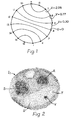
- Figure 1 is a diagram of an example using an array of sixteen surface electrodes equi-spaced round a body;
- Figure 2 is a print-out tomographic image of one cross-section of a human arm using the electrode array of Figure 1;
- Figure 3 is the corresponding image on a visual display unit (VDU);
- Figure 4 is the corresponding actual cross-section of the human arm;
- Figure 5 is a block circuit diagram of equipment used in conjunction with the electrode array of Figure 1 to produce the tomographic images of Figures 2 and 3;
- Figures 6 a-nd 7 are diagrams illustrating two ways of inducing currents in a body; and
- Figures 8 and 9 are diagrams illustrating respectively a linear array of electrodes in a block, and the use of blocks of contoured arrays of electrodes.
- Referring to Figures 1 and 5, an applied potential of approximately 3 volts at 4 milliamps is produced by a waveform generator A at 50kHz and applied through a voltage to current converter B and a multiplexer C in turn between every electrode combination and in each and every case the resultant potential between every adjacent pair of electrodes is fed through an amplifier D and a phase sensitive detector E and is recorded by a sample and hold unit F, from which the data is fed through a 12-Bit analogue to digital converter G to a computer H. The units A, E, F and G of the equipment are all controlled by a master clock J, which also controls the multiplexer through a unit K which stores the electrode combinations. The sixteen electrodes shown in Figure 1 give rise to 1456 potential measurements which can be recorded in 1.456 seconds or less.
- Figure 1 also shows the isopotentials to be expected when current is applied between
electrodes8and 16 on a body L assumed to consist of one uniform medium. In Figure 5 the sixteen electrodes are to be considered as . being equi-spaced around a human arm M at the cross-section shown in Figure 4. The recorded potentials are compared by the computer H with the respective calculated potentials and the ratios are back projected along the appropriate isopotentials. Thus twelve or thirteen back projections can be made for every pair of current drive electrodes (a potential cannot be recorded from a current drive electrode) and the modified isopotentials plotted. The plots of the modified impedance along isopotentials are superimposed on those obtained for each and every pair of drive electrodes, by means of the computer linked to a print-out N, to give a tomographic image I1 as in Figure 2, and to a visual display unit (VDU) P, to give a visually displayed image I2 as in Figure 3. - Comparing Figures 2, 3 and 4 it is possible to identify in the images I1 and I2 the radius and ulna banes R, S respectively, the radial and ulna arteries T, U respectively, and the median nerve V. With greater resolution of the images more constituent parts of the arm M could be identified.
- In addition to improving the resolution by iteration, the resolution can also be improved by increasing the number of electrodes to say 32, but this will call for more elaborate computing equipment to handle the increased number of recordings and calculations.
- In Figure 6 a coil W electromagnetically induces a current in a body X and an inhomogeneity Y causes surface potentials to be induced and which can be picked up by electrodes disposed as in Figure 1 and processed by modified equipment as in Figure 5, while in Figure 7 currents are induced by a plurality of coils Z equi-spaced around the body X.
- In Figure 8 a linear array of electrodes is mounted in a block 01, while in Figure 9 blocks 02, 03, 04 of contoured arrays of electrodes correspond to parts of the contour of a body.
- The method of the invention can also be applied to tomographic image construction from three-dimensional data, but this involves taking into account the spread of current out of the plane of the electrodes and either' back projection has to be made over isopotential surfaces, or the three-dimensional data reduced to two-dimensional format, which - again - calls for more elaborate computing equipment.
Claims (10)
Applications Claiming Priority (2)
| Application Number | Priority Date | Filing Date | Title |
|---|---|---|---|
| GB8212676 | 1982-04-30 | ||
| GB8212676 | 1982-04-30 |
Publications (2)
| Publication Number | Publication Date |
|---|---|
| EP0094113A2 true EP0094113A2 (en) | 1983-11-16 |
| EP0094113A3 EP0094113A3 (en) | 1985-05-22 |
Family
ID=10530116
Family Applications (1)
| Application Number | Title | Priority Date | Filing Date |
|---|---|---|---|
| EP83200598A Withdrawn EP0094113A3 (en) | 1982-04-30 | 1983-04-26 | Tomography |
Country Status (4)
| Country | Link |
|---|---|
| EP (1) | EP0094113A3 (en) |
| JP (1) | JPS5917329A (en) |
| CA (1) | CA1207083A (en) |
| GB (1) | GB2119520B (en) |
Cited By (3)
| Publication number | Priority date | Publication date | Assignee | Title |
|---|---|---|---|---|
| EP0172616A2 (en) * | 1984-06-14 | 1986-02-26 | The University Of Sheffield | Tomography |
| CN103976734A (en) * | 2014-05-09 | 2014-08-13 | 思澜科技(成都)有限公司 | Electrode ring for mammary electrical impedance tomography |
| CN114081468A (en) * | 2022-01-19 | 2022-02-25 | 北京华睿博视医学影像技术有限公司 | Electrode slice and electrode strip with quasi-periodic concave-convex liquid holding structure |
Families Citing this family (15)
| Publication number | Priority date | Publication date | Assignee | Title |
|---|---|---|---|---|
| US4955383A (en) * | 1988-12-22 | 1990-09-11 | Biofield Corporation | Discriminant function analysis method and apparatus for disease diagnosis and screening |
| GB9113830D0 (en) * | 1991-06-27 | 1991-08-14 | Brown Brian H | Applied potential tomography |
| JPH07369A (en) * | 1991-10-07 | 1995-01-06 | Agency Of Ind Science & Technol | High-speed imaging method of internal impedance distribution |
| DE4134960A1 (en) * | 1991-10-23 | 1993-04-29 | Popp Fritz Albert Dr | METHOD FOR A HOLISTIC ANALYSIS OF THE HEALTH CONDITION |
| US5217022A (en) * | 1991-11-27 | 1993-06-08 | Cornell Research Foundation, Inc. | Electrical impedance imaging to monitor myometrial activity |
| GB2276462B (en) * | 1993-03-23 | 1997-01-22 | Univ Sheffield | Method and apparatus for mapping of semiconductor materials |
| DE4332257C2 (en) * | 1993-09-22 | 1996-09-19 | P Osypka Gmbh Medizintechnik D | Device for generating tomographic images |
| RU2127075C1 (en) | 1996-12-11 | 1999-03-10 | Корженевский Александр Владимирович | Method for producing tomographic image of body and electrical-impedance tomographic scanner |
| US6940286B2 (en) | 2000-12-30 | 2005-09-06 | University Of Leeds | Electrical impedance tomography |
| US6980852B2 (en) * | 2002-01-25 | 2005-12-27 | Subqiview Inc. | Film barrier dressing for intravascular tissue monitoring system |
| JP5756132B2 (en) * | 2010-03-16 | 2015-07-29 | スイストム・アクチェンゲゼルシャフトSwisstom Ag | Electrode for scanning electrical impedance tomography apparatus, and scanning electrical impedance tomography apparatus |
| TWI461180B (en) * | 2011-12-30 | 2014-11-21 | Univ Nat Chiao Tung | Method for improving imaging resolution of electrical impedance tomography |
| JP7179552B2 (en) * | 2018-09-26 | 2022-11-29 | 日置電機株式会社 | Processing equipment and processing method |
| RU2748900C1 (en) * | 2020-09-30 | 2021-06-01 | федеральное государственное бюджетное образовательное учреждение высшего образования "Южно-Российский государственный политехнический университет (НПИ) имени М.И. Платова" | Method for visualizing perfusion field of thoracic cavity tissues based on electrical impedance tomography |
| RU2749298C1 (en) * | 2020-09-30 | 2021-06-08 | федеральное государственное бюджетное образовательное учреждение высшего образования "Южно-Российский государственный политехнический университет (НПИ) имени М.И. Платова" | Method for visualization of ventilation field based on electrical impedance tomography |
Citations (7)
| Publication number | Priority date | Publication date | Assignee | Title |
|---|---|---|---|---|
| DD117175A1 (en) * | 1974-11-29 | 1976-01-05 | ||
| US3971365A (en) * | 1973-02-12 | 1976-07-27 | Beckman Instruments, Inc. | Bioelectrical impedance measuring system |
| DE2726630A1 (en) * | 1976-06-14 | 1977-12-22 | Jean Duroux | METHOD AND DEVICE FOR THE INVESTIGATION OF INTERNAL PHYSIOLOGICAL PROCEDURES |
| DD139085A1 (en) * | 1978-09-27 | 1979-12-12 | Michael Tischmeyer | CIRCUIT ARRANGEMENT FOR MEASURING ELECTRODE-SKIN-TRANSITION RESISTANCES |
| US4263920A (en) * | 1978-03-25 | 1981-04-28 | Manfred Tasto | Method of and device for determining internal body structure |
| US4270545A (en) * | 1976-04-20 | 1981-06-02 | Rodler Ing Hans | Apparatus for examining biological bodies with electromagnetic fields |
| EP0085490A1 (en) * | 1982-01-12 | 1983-08-10 | Tasc Ltd. | Method and apparatus for imaging the interior of a structure |
Family Cites Families (1)
| Publication number | Priority date | Publication date | Assignee | Title |
|---|---|---|---|---|
| JPS582118A (en) * | 1981-06-29 | 1983-01-07 | Mitsubishi Metal Corp | Apparatus for aligning articles in many rows and stages |
-
1983
- 1983-04-22 GB GB08311065A patent/GB2119520B/en not_active Expired
- 1983-04-26 EP EP83200598A patent/EP0094113A3/en not_active Withdrawn
- 1983-04-28 JP JP58074178A patent/JPS5917329A/en active Granted
- 1983-04-29 CA CA000427049A patent/CA1207083A/en not_active Expired
Patent Citations (7)
| Publication number | Priority date | Publication date | Assignee | Title |
|---|---|---|---|---|
| US3971365A (en) * | 1973-02-12 | 1976-07-27 | Beckman Instruments, Inc. | Bioelectrical impedance measuring system |
| DD117175A1 (en) * | 1974-11-29 | 1976-01-05 | ||
| US4270545A (en) * | 1976-04-20 | 1981-06-02 | Rodler Ing Hans | Apparatus for examining biological bodies with electromagnetic fields |
| DE2726630A1 (en) * | 1976-06-14 | 1977-12-22 | Jean Duroux | METHOD AND DEVICE FOR THE INVESTIGATION OF INTERNAL PHYSIOLOGICAL PROCEDURES |
| US4263920A (en) * | 1978-03-25 | 1981-04-28 | Manfred Tasto | Method of and device for determining internal body structure |
| DD139085A1 (en) * | 1978-09-27 | 1979-12-12 | Michael Tischmeyer | CIRCUIT ARRANGEMENT FOR MEASURING ELECTRODE-SKIN-TRANSITION RESISTANCES |
| EP0085490A1 (en) * | 1982-01-12 | 1983-08-10 | Tasc Ltd. | Method and apparatus for imaging the interior of a structure |
Cited By (5)
| Publication number | Priority date | Publication date | Assignee | Title |
|---|---|---|---|---|
| EP0172616A2 (en) * | 1984-06-14 | 1986-02-26 | The University Of Sheffield | Tomography |
| EP0172616A3 (en) * | 1984-06-14 | 1987-03-04 | The University Of Sheffield | Tomography |
| CN103976734A (en) * | 2014-05-09 | 2014-08-13 | 思澜科技(成都)有限公司 | Electrode ring for mammary electrical impedance tomography |
| WO2015169255A1 (en) * | 2014-05-09 | 2015-11-12 | 思澜科技(成都)有限公司 | Electrode ring for electrical impedance tomography imaging of breast |
| CN114081468A (en) * | 2022-01-19 | 2022-02-25 | 北京华睿博视医学影像技术有限公司 | Electrode slice and electrode strip with quasi-periodic concave-convex liquid holding structure |
Also Published As
| Publication number | Publication date |
|---|---|
| GB2119520B (en) | 1985-05-15 |
| CA1207083A (en) | 1986-07-02 |
| GB8311065D0 (en) | 1983-05-25 |
| JPS5917329A (en) | 1984-01-28 |
| EP0094113A3 (en) | 1985-05-22 |
| GB2119520A (en) | 1983-11-16 |
| JPH0414006B2 (en) | 1992-03-11 |
Similar Documents
| Publication | Publication Date | Title |
|---|---|---|
| US4617939A (en) | Tomography | |
| EP0094113A2 (en) | Tomography | |
| US6167300A (en) | Electric mammograph | |
| Barber et al. | Applied potential tomography | |
| Oh et al. | Conductivity and current density image reconstruction using harmonic Bz algorithm in magnetic resonance electrical impedance tomography | |
| Henderson et al. | An impedance camera for spatially specific measurements of the thorax | |
| Barber | A review of image reconstruction techniques for electrical impedance tomography | |
| Cheng et al. | Electrode models for electric current computed tomography | |
| EP0052128B1 (en) | Apparatus and method for image reproduction of materials using their magnetic and electric properties | |
| Choi et al. | A reconstruction algorithm for breast cancer imaging with electrical impedance tomography in mammography geometry | |
| US6501984B1 (en) | Electrical impedance tomography method and electrode arrangement for use therein | |
| EP0085490A1 (en) | Method and apparatus for imaging the interior of a structure | |
| US7603158B2 (en) | Current density impedance imaging (CDII) | |
| JP5033307B2 (en) | Method and apparatus for creating an electrical property image of a substantially uniform object including heterogeneous portions | |
| Saulnier et al. | An electrical impedance spectroscopy system for breast cancer detection | |
| Dimas et al. | Electrical impedance tomography image reconstruction for adjacent and opposite strategy using FEMM and EIDORS simulation models | |
| Özdemir et al. | Equipotential projection-based magnetic resonance electrical impedance tomography and experimental realization | |
| GB2486967A (en) | Soft Field Tomography Iteration Method | |
| Kwon et al. | Estimation of anomaly location and size using electrical impedance tomography | |
| CA1220863A (en) | Tomography | |
| Brown et al. | Tomography | |
| Babaeizadeh et al. | Electrode boundary conditions and experimental validation for BEM-based EIT forward and inverse solutions | |
| Korjenevsky | Reconstruction of absolute conductivity distribution in electrical impedance tomography | |
| Xu et al. | The acquisition hardware system with direct digital synthesis and filtered back-projection imaging in electrical impedance tomography | |
| Caeiros et al. | A differential high-resolution motorized multi-projection approach for an experimental Magnetic Induction Tomography prototype |
Legal Events
| Date | Code | Title | Description |
|---|---|---|---|
| PUAI | Public reference made under article 153(3) epc to a published international application that has entered the european phase |
Free format text: ORIGINAL CODE: 0009012 |
|
| AK | Designated contracting states |
Designated state(s): AT BE CH DE FR GB IT LI LU NL SE |
|
| RAP1 | Party data changed (applicant data changed or rights of an application transferred) |
Owner name: THE UNIVERSITY OF SHEFFIELD |
|
| 17P | Request for examination filed |
Effective date: 19840402 |
|
| PUAL | Search report despatched |
Free format text: ORIGINAL CODE: 0009013 |
|
| AK | Designated contracting states |
Designated state(s): AT BE CH DE FR GB IT LI LU NL SE |
|
| 17Q | First examination report despatched |
Effective date: 19861110 |
|
| STAA | Information on the status of an ep patent application or granted ep patent |
Free format text: STATUS: THE APPLICATION HAS BEEN WITHDRAWN |
|
| R17C | First examination report despatched (corrected) |
Effective date: 19870325 |
|
| 18W | Application withdrawn |
Withdrawal date: 19870502 |
|
| RIN1 | Information on inventor provided before grant (corrected) |
Inventor name: BARBER, DAVID CHARLES Inventor name: BROWN, BRIAN HILTON Inventor name: FREESTON, IAN LESLIE |