EP0093524B1 - Electric cable glands - Google Patents
Electric cable glands Download PDFInfo
- Publication number
- EP0093524B1 EP0093524B1 EP83302094A EP83302094A EP0093524B1 EP 0093524 B1 EP0093524 B1 EP 0093524B1 EP 83302094 A EP83302094 A EP 83302094A EP 83302094 A EP83302094 A EP 83302094A EP 0093524 B1 EP0093524 B1 EP 0093524B1
- Authority
- EP
- European Patent Office
- Prior art keywords
- cable
- members
- tubular members
- sealing material
- termination
- Prior art date
- Legal status (The legal status is an assumption and is not a legal conclusion. Google has not performed a legal analysis and makes no representation as to the accuracy of the status listed.)
- Expired
Links
Images
Classifications
-
- H—ELECTRICITY
- H02—GENERATION; CONVERSION OR DISTRIBUTION OF ELECTRIC POWER
- H02G—INSTALLATION OF ELECTRIC CABLES OR LINES, OR OF COMBINED OPTICAL AND ELECTRIC CABLES OR LINES
- H02G3/00—Installations of electric cables or lines or protective tubing therefor in or on buildings, equivalent structures or vehicles
- H02G3/02—Details
- H02G3/06—Joints for connecting lengths of protective tubing or channels, to each other or to casings, e.g. to distribution boxes; Ensuring electrical continuity in the joint
- H02G3/0616—Joints for connecting tubing to casing
-
- H—ELECTRICITY
- H02—GENERATION; CONVERSION OR DISTRIBUTION OF ELECTRIC POWER
- H02G—INSTALLATION OF ELECTRIC CABLES OR LINES, OR OF COMBINED OPTICAL AND ELECTRIC CABLES OR LINES
- H02G15/00—Cable fittings
- H02G15/02—Cable terminations
- H02G15/04—Cable-end sealings
-
- H—ELECTRICITY
- H02—GENERATION; CONVERSION OR DISTRIBUTION OF ELECTRIC POWER
- H02G—INSTALLATION OF ELECTRIC CABLES OR LINES, OR OF COMBINED OPTICAL AND ELECTRIC CABLES OR LINES
- H02G3/00—Installations of electric cables or lines or protective tubing therefor in or on buildings, equivalent structures or vehicles
- H02G3/02—Details
- H02G3/08—Distribution boxes; Connection or junction boxes
- H02G3/088—Dustproof, splashproof, drip-proof, waterproof, or flameproof casings or inlets
-
- Y—GENERAL TAGGING OF NEW TECHNOLOGICAL DEVELOPMENTS; GENERAL TAGGING OF CROSS-SECTIONAL TECHNOLOGIES SPANNING OVER SEVERAL SECTIONS OF THE IPC; TECHNICAL SUBJECTS COVERED BY FORMER USPC CROSS-REFERENCE ART COLLECTIONS [XRACs] AND DIGESTS
- Y10—TECHNICAL SUBJECTS COVERED BY FORMER USPC
- Y10T—TECHNICAL SUBJECTS COVERED BY FORMER US CLASSIFICATION
- Y10T29/00—Metal working
- Y10T29/49—Method of mechanical manufacture
- Y10T29/49002—Electrical device making
- Y10T29/49117—Conductor or circuit manufacturing
- Y10T29/49174—Assembling terminal to elongated conductor
- Y10T29/49176—Assembling terminal to elongated conductor with molding of electrically insulating material
Definitions
- This invention relates to terminations for electric cables with metallic sheaths or other metallic covering layers and a method of making them.
- a cable gland (commonly referred to as a "Barrier Gland”) comprising two tubular members each wider at one end than at the other and telescopically engageable at their respective wider ends to define an annular chamber around a cable end inserted through the telescoped members, and means for urging the tubular members axially together to reduce the volume of the annular chamber.
- the annular chamber is filled with a hard- setting insulating sealing material in a pasty or viscous condition, and the insulating sealing material is pressurised by urging the tubular members together before it sets, in order to provide a fluid-tight, pressure-tight and/or flameproof seal.
- the tubular members are preferably urged together by outer members that enclose them and are screwed together either by a direct threaded engagement between them or with drawbolts or the like; when a flameproof gland is required, one of the outer members should fit one of the tubular members closely enough over a sufficient axial length to form a joint that satisfies flameproof requirements (a flame gap or flameproof path); typical requirements for an unthreaded joint would be for a diametral clearance less than 0.3 mm and an axial length of at least 12.5 mm. Manufacturing tolerances in such cases can be eased by centring, e.g. by providing them with mating conical surfaces.
- the present invention is characterised by the fact that at least one resilient contact finger in electrical continuity with and projecting inwardly from one of the tubular members of the gland to contact a conductive part of the cable is embedded in, and locked in position by, the set insulating sealing material.
- the set insulating sealing material holds them rigidly in fixed positions in the finished termination.
- the finger or fingers may be supported at one or both ends; the width of the (or each) finger may vary along its length, but will be small compared with the circumference of the annular chamber.
- This body may be force-fitted in the relevant tubular member or could be welded, rivetted or otherwise secured to it.
- the finger(s), if supported at one end only, may extend either radially or obliquely, in the latter case preferably with the free end(s) nearer to the position that will be occupied by the apparatus to which the cable is to be connected than the fixed end(s).
- terminations of the inventions of the invention are primarily intended for use with corrugated cable sheaths of aluminium, copper, steel, etc., they can be made effectively on cables that include a smooth metallic sheath, e.g. of lead, or lapped tape armour of tinned steel etc.
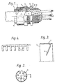
- this shows a flameproof termination for a three-core electric cable with a corrugated metal sheath 1 and a protective oversheath 2 of plastics material.
- a contact ring 3 is made by taking a short length from a phosphor bronze strip previously punched to form a number of fingers on one of its sides, rolling the cut length to form it into a tube and then bending each of the fingers 4 ( Figures 2 and 3) sharply so as to exceed the elastic limit and leave each finger projecting radially inwards; the circular form can be retained by a circlip, interlocking, welding, etc., if required.
- Figure 4 shows one form of punched strip, which, cut to appropriate lengths, can be used for various sizes of contact ring.
- the opposite side 5 of the phosphor bronze strip may be flanged if desired to strengthen it.
- This contact ring is snap- fitted into an undercut recess in the inner surface of a first tubular member 6 ( Figure 1) which is wider at its right hand end than its left.
- This tubular member 6 supports an outer seal assembly 7 consisting of an elastomeric sealing ring 8 with skid washers 9 and a gland nut 10 threaded on the tubular member 6.
- This assembly together with an outer gland nut 11 (whose function is to be explained later) is slipped over the prepared cable end and the gland nut 10 is tightened to compress the sealing ring 8 and so locate the tubular member 6 on the cable end.
- a second tubular member 12 which is wider at its left hand end than its right hand end, is now threaded over the ends of the conductors 13 and telescoped with the free end of the tubular member 6.
- Members 6 and 12 are then urged together using the outer gland nut 11 and an outer body member 14 which are screw threaded together.
- the body 14 may already be fitted in the apparatus to which a connection is to be made, or it could be fitted later, as detailed below.
- the tubular member 12 is self-centring in the body portion 14 through the action of conical contact surfaces at 16 and the length of the joint between them (which is in fact the full length of the body 14), is sufficient to ensure a joint that meets flameproof requirements.
- the insulating sealing material When the insulating sealing material is set, it adheres firmly to the tubular members 6 and 12, but the outer members 11 and 14 are not in contact with the insulating sealing material and can be unscrewed as required. If the body member is not already fixed in position in the apparatus, the outer gland nut 11 can be unscrewed to allow the body member 14 to be rotated for screwing it into the wall of the apparatus, and the gland then re-assembled. This process can be repeated, without detriment to the seal, if it is necessary to replace the whole or any relevant part of the apparatus.
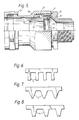
- the gland shown in Figure 5 is designed for use with a cable having wire armour over the sheathing layer to which contact is to be made by the fingers 4.
- the first tubular member 17 (corresponding to 6 in Figure 1) is modified to provide a cone 18 on which the ends of the armour wires are laid and secured with a clamping ring 19 urged into engagement by a gland barrel 20 threaded on the body 14. This is done in a preliminary step prior to insertion of insulating sealing material into the chamber 15 in order to lock the tubular member 17 in position. After unscrewing the barrel, the subsequent procedure is substantially as before, except that the outer seal 21 needs to be tightened after the barrel has been finally screwed up.
- Figure 5 also illustrates the use of a circlip 22 to hold the finger assembly 3 more securely in position.
- the fingers 4 may be parallel-sided or tapered, and their ends may be straight, convex or concave.
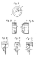
- a further alternative is to form the finger assembly from a seamless or welded tube 26 ( Figures 13 to 14) with the fingers 4 bent through an appropriate angle, either obtuse or acute. Two or more finger assemblies could be used for added security.
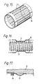
- Figures 15 to 17 illustrate the use of fingers that are supported at both ends, which may have advantages if the layer of the cable to be contacted is liable to be torn; for example a thin metal tape layer.
- Fingers 27 are formed by punching rectangular holes in a metal sheet which is subsequently rolled to form a tube 28 (or a preformed tube could be used, but is more difficult to fabricate); the fingers are bowed inwardly by applying axial pressure while preventing any outward movement (as shown in Figure 16) or by a squeezing action.
- Figure 17 illustrates one practical way of applying axial pressure by means of a ring 28 threaded in the mounting member 23.
Abstract
Description
- This invention relates to terminations for electric cables with metallic sheaths or other metallic covering layers and a method of making them.
- It is a normal requirement when glands are used in cable terminations to ensure "earth continuity" by providing an electrical connection between the cable sheath (or other conductive covering layer) and the body, or some other accessible member, of the gland. This presents difficulties, especially when the layer to be contacted is a corrugated sheath, as different manufacturers use different corrugation profiles (and some annular and others helical ones), and even for a given cable the effective contact radius varies rapidly along the length of the cable (and in the case of helical corrugations around the circumference as well).
- Contact-making devices comprising resilient contact fingers (US-A-4022966), usually backed up with rubber compression rings (US-A-2816949), have been tried but are not wholly satisfactory because movements under thermal and mechanical stresses are liable to result in insecure contacts, or even fracture of the fingers in some cases.
- The Applicants have been marketing for a number of years (GB-A-1524684) a cable gland (commonly referred to as a "Barrier Gland") comprising two tubular members each wider at one end than at the other and telescopically engageable at their respective wider ends to define an annular chamber around a cable end inserted through the telescoped members, and means for urging the tubular members axially together to reduce the volume of the annular chamber.
- In use, the annular chamber is filled with a hard- setting insulating sealing material in a pasty or viscous condition, and the insulating sealing material is pressurised by urging the tubular members together before it sets, in order to provide a fluid-tight, pressure-tight and/or flameproof seal.
- To allow the gland to be released, if required, from the apparatusto which the cable is connected without destroying the body of set insulating sealing material, the tubular members are preferably urged together by outer members that enclose them and are screwed together either by a direct threaded engagement between them or with drawbolts or the like; when a flameproof gland is required, one of the outer members should fit one of the tubular members closely enough over a sufficient axial length to form a joint that satisfies flameproof requirements (a flame gap or flameproof path); typical requirements for an unthreaded joint would be for a diametral clearance less than 0.3 mm and an axial length of at least 12.5 mm. Manufacturing tolerances in such cases can be eased by centring, e.g. by providing them with mating conical surfaces.
- Others (GB-A-2056191 ) have attempted to provide contact fingers in a barrier gland, but have located them outside the chamber filled with insulating sealing material.
- The present invention is characterised by the fact that at least one resilient contact finger in electrical continuity with and projecting inwardly from one of the tubular members of the gland to contact a conductive part of the cable is embedded in, and locked in position by, the set insulating sealing material.
- The set insulating sealing material holds them rigidly in fixed positions in the finished termination.
- The finger or fingers may be supported at one or both ends; the width of the (or each) finger may vary along its length, but will be small compared with the circumference of the annular chamber. Preferably there are a plurality of contact fingers distributed around the circumference of the gland; preferably they are all formed as inward projections from a common annular or nearly annular body, such as a split or solid tube or a slit or solid annular disc of a suitable resilient metal, for example beryllium copper, phosphor-bronze, stainless steel or even mild steel. This body may be force-fitted in the relevant tubular member or could be welded, rivetted or otherwise secured to it.
- Prior to fitting on the cable, the finger(s), if supported at one end only, may extend either radially or obliquely, in the latter case preferably with the free end(s) nearer to the position that will be occupied by the apparatus to which the cable is to be connected than the fixed end(s).
- Although the terminations of the inventions of the invention are primarily intended for use with corrugated cable sheaths of aluminium, copper, steel, etc., they can be made effectively on cables that include a smooth metallic sheath, e.g. of lead, or lapped tape armour of tinned steel etc.
- The invention will be further described by way of example with reference to the accompanying drawings in which:-
- Figure 1 is a cross-section through one particular form of termination in accordance with the invention; and
- Figure 2 is an end-view of a finger assembly forming part of the termination of Figure 1;
- Figure 3 is an enlarged, simplified cross-section of the line III-III in Figure 2;
- Figure 4 is a plan view of a length of stamped strip for making the finger assembly of Figure 2;
- Figure 5 is a partly-sectioned view of a modified form of gland in accordance with the invention;
- Figures 6-8 show stamped strips alternative to the one shown in Figure 4;
- Figure 9 is a composite view showing three forms of finger assembly alternative to the one shown Figure 2;
- Figures 10, 11 and 12 show three ways of making the assembly shown in Figure 9;
- Figures 13 and 14 show two more alternative finger assemblies, which can be used separately or together; and
- Figures 15 to 17 illustrate another alternative finger assembly and its use.
- Referring first to Figure 1, this shows a flameproof termination for a three-core electric cable with a
corrugated metal sheath 1 and aprotective oversheath 2 of plastics material. In making this termination, acontact ring 3 is made by taking a short length from a phosphor bronze strip previously punched to form a number of fingers on one of its sides, rolling the cut length to form it into a tube and then bending each of the fingers 4 (Figures 2 and 3) sharply so as to exceed the elastic limit and leave each finger projecting radially inwards; the circular form can be retained by a circlip, interlocking, welding, etc., if required. - Figure 4 shows one form of punched strip, which, cut to appropriate lengths, can be used for various sizes of contact ring. The
opposite side 5 of the phosphor bronze strip may be flanged if desired to strengthen it. This contact ring is snap- fitted into an undercut recess in the inner surface of a first tubular member 6 (Figure 1) which is wider at its right hand end than its left. This tubular member 6 supports an outer seal assembly 7 consisting of anelastomeric sealing ring 8 with skid washers 9 and agland nut 10 threaded on the tubular member 6. This assembly, together with an outer gland nut 11 (whose function is to be explained later) is slipped over the prepared cable end and thegland nut 10 is tightened to compress thesealing ring 8 and so locate the tubular member 6 on the cable end. - A suitable quantity of a resinous insulating sealing material in the form of a putty, such as that sold by the Applicants under the trade mark "Bicaseal", is now made up and filled into the open end of the tubular member 6, and into the crutch of the cable, to a diameter roughly equal to the diameter of the mouth of the tubular member 6.
- A second
tubular member 12, which is wider at its left hand end than its right hand end, is now threaded over the ends of the conductors 13 and telescoped with the free end of the tubular member 6.Members 6 and 12 are then urged together using theouter gland nut 11 and anouter body member 14 which are screw threaded together. Thebody 14 may already be fitted in the apparatus to which a connection is to be made, or it could be fitted later, as detailed below. By urging themembers 6 and 12 together, pressure is generated in the insulating sealing material in thechamber 15, ensuring that it is void-free and makes an effective seal as well as locking thefingers 4 in position. - The
tubular member 12 is self-centring in thebody portion 14 through the action of conical contact surfaces at 16 and the length of the joint between them (which is in fact the full length of the body 14), is sufficient to ensure a joint that meets flameproof requirements. - When the insulating sealing material is set, it adheres firmly to the
tubular members 6 and 12, but theouter members outer gland nut 11 can be unscrewed to allow thebody member 14 to be rotated for screwing it into the wall of the apparatus, and the gland then re-assembled. This process can be repeated, without detriment to the seal, if it is necessary to replace the whole or any relevant part of the apparatus. - The gland shown in Figure 5 is designed for use with a cable having wire armour over the sheathing layer to which contact is to be made by the
fingers 4. The first tubular member 17 (corresponding to 6 in Figure 1) is modified to provide acone 18 on which the ends of the armour wires are laid and secured with aclamping ring 19 urged into engagement by agland barrel 20 threaded on thebody 14. This is done in a preliminary step prior to insertion of insulating sealing material into thechamber 15 in order to lock thetubular member 17 in position. After unscrewing the barrel, the subsequent procedure is substantially as before, except that theouter seal 21 needs to be tightened after the barrel has been finally screwed up. - Figure 5 also illustrates the use of a
circlip 22 to hold thefinger assembly 3 more securely in position. - As illustrated by Figures 6 to 8, the
fingers 4 may be parallel-sided or tapered, and their ends may be straight, convex or concave. - As illustrated by Figures 7 to 12, instead of rolling the
finger assembly 3 from a punched strip and bending the fingers inwards, it may be stamped in flat disc form from sheet metal and thefingers 4 subsequently bent outwards (if necessary); the disc form assembly may be force-fitted in the tubular mounting member 33 (Figure 10), locked in position by local deformations 24 (Figure 11) or secured with a threaded ring 25 (Figure 12). - A further alternative is to form the finger assembly from a seamless or welded tube 26 (Figures 13 to 14) with the
fingers 4 bent through an appropriate angle, either obtuse or acute. Two or more finger assemblies could be used for added security. - Figures 15 to 17 illustrate the use of fingers that are supported at both ends, which may have advantages if the layer of the cable to be contacted is liable to be torn; for example a thin metal tape layer.
Fingers 27 are formed by punching rectangular holes in a metal sheet which is subsequently rolled to form a tube 28 (or a preformed tube could be used, but is more difficult to fabricate); the fingers are bowed inwardly by applying axial pressure while preventing any outward movement (as shown in Figure 16) or by a squeezing action. Figure 17 illustrates one practical way of applying axial pressure by means of aring 28 threaded in themounting member 23.
Claims (6)
Priority Applications (1)
| Application Number | Priority Date | Filing Date | Title |
|---|---|---|---|
| AT83302094T ATE37969T1 (en) | 1982-04-22 | 1983-04-14 | GLANDS FOR ELECTRICAL CABLES. |
Applications Claiming Priority (2)
| Application Number | Priority Date | Filing Date | Title |
|---|---|---|---|
| GB8211669 | 1982-04-22 | ||
| GB8211669 | 1982-04-22 |
Publications (3)
| Publication Number | Publication Date |
|---|---|
| EP0093524A2 EP0093524A2 (en) | 1983-11-09 |
| EP0093524A3 EP0093524A3 (en) | 1986-03-19 |
| EP0093524B1 true EP0093524B1 (en) | 1988-10-12 |
Family
ID=10529863
Family Applications (1)
| Application Number | Title | Priority Date | Filing Date |
|---|---|---|---|
| EP83302094A Expired EP0093524B1 (en) | 1982-04-22 | 1983-04-14 | Electric cable glands |
Country Status (8)
| Country | Link |
|---|---|
| US (1) | US4515991A (en) |
| EP (1) | EP0093524B1 (en) |
| JP (1) | JPS58192421A (en) |
| AT (1) | ATE37969T1 (en) |
| CA (1) | CA1179029A (en) |
| DE (1) | DE3378242D1 (en) |
| HK (1) | HK118993A (en) |
| MY (1) | MY100303A (en) |
Families Citing this family (57)
| Publication number | Priority date | Publication date | Assignee | Title |
|---|---|---|---|---|
| SE445408B (en) * | 1984-09-26 | 1986-06-16 | Ake Bladh | The cable plate |
| US4686381A (en) * | 1986-06-30 | 1987-08-11 | Hubbell Incorporated | Overhead wiring system |
| US4885429A (en) * | 1989-01-10 | 1989-12-05 | Hubbell Incorporated | Metal clad cable connector |
| DE3914029A1 (en) * | 1989-04-28 | 1990-10-31 | Messerschmitt Boelkow Blohm | Screen connection element for low current cable - consisting of plug and socket with coaxial inner conductor located in plug and socket |
| GB2233838A (en) * | 1989-06-30 | 1991-01-16 | Hawke Cable Glands Ltd | Cable glands |
| US5059747A (en) * | 1989-12-08 | 1991-10-22 | Thomas & Betts Corporation | Connector for use with metal clad cable |
| US5015804A (en) * | 1990-03-26 | 1991-05-14 | Commander Electrical Materials, Inc. | Electrical cable connector for sealing an armoured electrical cable |
| US5208427A (en) * | 1992-01-31 | 1993-05-04 | Thomas & Betts Corporation | Connector for terminating electrical cable assemblies of multiple configurations |
| US5321205B1 (en) * | 1993-01-15 | 1997-02-04 | Thomas & Betts Corp | Electrical connector fitting |
| US5374785A (en) * | 1993-01-26 | 1994-12-20 | Thomas & Betts Corporation | Hub locknut |
| GB2302618B (en) * | 1995-06-24 | 1998-11-04 | Hawke Cable Glands Ltd | Electric cable termination gland |
| DE19615602A1 (en) * | 1996-04-19 | 1997-10-23 | Lapp U I Gmbh & Co Kg | Cable gland |
| US5951327A (en) * | 1997-09-29 | 1999-09-14 | Thomas & Betts International, Inc. | Connector for use with multiple sizes of cables |
| GB2336041B (en) * | 1998-03-27 | 2002-03-13 | Hawke Cable Glands Ltd | Cable gland |
| JP2001063490A (en) * | 1999-08-25 | 2001-03-13 | Yazaki Corp | Erroneous assembly preventing structure for grommet |
| GB2356742B (en) * | 1999-11-24 | 2002-10-16 | David Curry | Grip gland for electrical cables |
| US6274816B1 (en) * | 1999-12-10 | 2001-08-14 | Clarence E. Kendall, Jr. | Welded connector for insulated conductors in metal tubings |
| US6730849B2 (en) * | 2001-10-12 | 2004-05-04 | Juergen Koessler | Through-fittings and below grade junction boxes equipped with same |
| US7390027B2 (en) * | 2003-08-13 | 2008-06-24 | Bridgeport Fittings, Inc. | Weatherproof compression connecting assembly for securing electrical metal tubing |
| DE102006008457A1 (en) * | 2005-04-08 | 2006-10-12 | Lapp Engineering & Co. | Grommet |
| US20070134349A1 (en) * | 2005-09-19 | 2007-06-14 | Duke University | Methods of treating hematological malignancies |
| US7507907B2 (en) | 2006-09-22 | 2009-03-24 | Lapp Engineering & Co. | Cable feed-through |
| US7633011B2 (en) * | 2006-11-14 | 2009-12-15 | Egs Electrical Group Llc | Expansion coupling with ground for an electrical metal conduit |
| US9252586B2 (en) * | 2006-11-15 | 2016-02-02 | Pratley Investments (Propietary) Limited | Method for forming a seal on conductors of an electrical cable |
| GB0809953D0 (en) * | 2008-05-31 | 2008-07-09 | Cmp Products Ltd | Cable gland seal |
| US8050528B2 (en) | 2008-06-05 | 2011-11-01 | Channell Commercial Corporation | Sealing gland system |
| US8460031B2 (en) * | 2008-11-05 | 2013-06-11 | Andrew Llc | Coaxial connector with cable diameter adapting seal assembly and interconnection method |
| EP2406775B1 (en) * | 2009-03-12 | 2014-07-23 | Checkpoint Systems, Inc. | Disposable cable lock and detachable alarm module |
| KR101835066B1 (en) | 2009-08-21 | 2018-03-06 | 씨엠피 프로덕츠 리미티드 | Filler assembly for cable gland |
| US10193321B2 (en) | 2009-08-21 | 2019-01-29 | Cmp Products Limited | Filler assembly for cable gland |
| DE202009016477U1 (en) | 2009-11-25 | 2010-06-17 | Hidde, Axel R., Dr. | Electrical contacting device for cable and shielding |
| CN203347377U (en) | 2010-04-30 | 2013-12-18 | 关卡系统公司 | Security component for fixing articles |
| US8657626B2 (en) | 2010-12-02 | 2014-02-25 | Thomas & Betts International, Inc. | Cable connector with retaining element |
| DE102010064071B3 (en) * | 2010-12-23 | 2012-05-24 | Tyco Electronics Amp Gmbh | Clamping ring, cable gland and method for mounting a cable gland |
| US8152537B1 (en) | 2011-03-31 | 2012-04-10 | John Mezzalingua Associates, Inc. | Split conductive mid-span ground clamp |
| US8636524B2 (en) | 2011-03-31 | 2014-01-28 | John Mezzalingua Associates, LLC | Split conductive mid-span ground clamp |
| US8152559B1 (en) | 2011-03-31 | 2012-04-10 | John Mezzalingua Associates, Inc. | Split compression mid-span ground clamp |
| US8366459B2 (en) | 2011-03-31 | 2013-02-05 | John Mezzalingua Associates, Inc. | Compression style mid-span ground clamp |
| US8692139B2 (en) * | 2011-09-06 | 2014-04-08 | Cooper Technologies Company | Cable gland assembly for terminating cable |
| US8562361B2 (en) * | 2011-10-11 | 2013-10-22 | The United States Of America As Represented By The Secretary Of The Navy | Universal ground adapter for marine cables |
| US9054433B2 (en) * | 2011-10-11 | 2015-06-09 | The United States Of America As Represented By The Secretary Of The Navy | Junction box fitting for marine cables |
| US8747126B2 (en) | 2011-10-11 | 2014-06-10 | The United States Of America As Represented By The Secretary Of The Navy | Universal ground adapter for marine cables |
| US8513543B1 (en) * | 2012-02-21 | 2013-08-20 | Asia Tai Technology Co., Ltd. | Water-proofing cable connector |
| US9343883B2 (en) | 2013-03-14 | 2016-05-17 | Bridgeport Fittings, Inc. | Raintight compression connector and raintight compression coupler for securing electrical metallic tubing or rigid metallic conduit |
| US10240694B2 (en) | 2013-10-31 | 2019-03-26 | Bridgeport Fittings, Inc. | Co-molded sealing ring for use in an electrical fitting, and a raintight compression connector and raintight compression coupler incorporating a co-molded sealing ring |
| USD787648S1 (en) | 2013-10-31 | 2017-05-23 | Bridgeport Fittings, Inc. | Raintight fitting connector body |
| US9787070B2 (en) | 2013-10-31 | 2017-10-10 | Bridgeport Fittings, Inc. | Raintight compression connector and raintight compression coupler for securing electrical metallic tubing or rigid metallic conduit |
| US9793624B2 (en) | 2013-12-24 | 2017-10-17 | Ppc Broadband, Inc. | Connector having an inner conductor engager |
| WO2016019081A1 (en) | 2014-07-30 | 2016-02-04 | Corning Optical Communications Rf Llc | Coaxial cable connectors with conductor retaining members |
| EP3239044B1 (en) * | 2014-10-27 | 2019-12-25 | Guangzhou Xaircraft Technology Co., Ltd. | Rotorcraft and assembly and disassembly structure for foot stand and airframe of rotorcraft |
| EP3716430A1 (en) * | 2019-03-27 | 2020-09-30 | ABB Schweiz AG | Method of providing emc protection for electric cable assembly, and emc protected electric cable assembly manufactured by said method |
| EP3997769A1 (en) * | 2019-07-12 | 2022-05-18 | Hubbell Incorporated | Liquid epoxy brush barrier |
| EP3787123B1 (en) | 2019-08-28 | 2023-01-18 | Etel S.A. | Cable shield connecting assembly for electrical device and method for securing and grounding a cable to a cylindrical housing of an electric rotary motor |
| US11631971B2 (en) * | 2020-10-19 | 2023-04-18 | CCG International Holdings Limited | Cable gland for armored electrical or fiber optic cables |
| US20220208419A1 (en) * | 2020-12-30 | 2022-06-30 | Eaton Intelligent Power Limited | Additively Manufactured Cable Gland |
| CN117063363A (en) * | 2021-08-30 | 2023-11-14 | 哈勃股份有限公司 | Adaptive seal for cable gland |
| EP4167410A1 (en) * | 2021-10-12 | 2023-04-19 | Eaton Intelligent Power Limited | Cable gland for armored cable |
Family Cites Families (13)
| Publication number | Priority date | Publication date | Assignee | Title |
|---|---|---|---|---|
| GB430356A (en) * | 1933-12-18 | 1935-06-18 | George Arthur Hinds | Improvements relating to flexible pipe connections |
| GB700887A (en) * | 1951-10-01 | 1953-12-09 | Chicago Forging & Mfg Co | Improvements in fittings or connections for tubing |
| US2816949A (en) * | 1952-11-17 | 1957-12-17 | Thomas & Betts Corp | Armoured cable mounting |
| US3219751A (en) * | 1962-06-27 | 1965-11-23 | Bendix Corp | Coupling device with deformable gripper fingers for connecting telescoping members |
| US3783178A (en) * | 1972-08-03 | 1974-01-01 | Gen Signal Corp | Expansion joint for connecting rigid conduit with grounding continuity |
| JPS49117492U (en) * | 1973-02-06 | 1974-10-07 | ||
| US4015329A (en) * | 1974-12-20 | 1977-04-05 | John Blundell Hutchison | Termination of electric cables |
| GB1524683A (en) * | 1974-12-20 | 1978-09-13 | Bicc Ltd | Termination of electric cables |
| GB1524684A (en) * | 1975-12-22 | 1978-09-13 | Bicc Ltd | Termination of electric cables |
| US4022966A (en) * | 1976-06-16 | 1977-05-10 | I-T-E Imperial Corporation Efcor Division | Ground connector |
| GB1603499A (en) * | 1978-05-19 | 1981-11-25 | British Eng Ltd | Cable glands |
| GB2056191A (en) * | 1979-06-15 | 1981-03-11 | British Engines Ltd | Improvements in, or relating to, cable seals |
| US4273405A (en) * | 1979-08-13 | 1981-06-16 | Thomas & Betts Corporation | Jacketed metal clad cable connector |
-
1982
- 1982-05-21 CA CA000403544A patent/CA1179029A/en not_active Expired
-
1983
- 1983-04-05 US US06/482,144 patent/US4515991A/en not_active Expired - Lifetime
- 1983-04-14 DE DE8383302094T patent/DE3378242D1/en not_active Expired
- 1983-04-14 EP EP83302094A patent/EP0093524B1/en not_active Expired
- 1983-04-14 AT AT83302094T patent/ATE37969T1/en not_active IP Right Cessation
- 1983-04-20 JP JP58068467A patent/JPS58192421A/en active Granted
-
1986
- 1986-11-27 MY MYPI86000149A patent/MY100303A/en unknown
-
1993
- 1993-11-04 HK HK1189/93A patent/HK118993A/en not_active IP Right Cessation
Also Published As
| Publication number | Publication date |
|---|---|
| JPH0410294B2 (en) | 1992-02-24 |
| JPS58192421A (en) | 1983-11-09 |
| HK118993A (en) | 1993-11-12 |
| EP0093524A2 (en) | 1983-11-09 |
| CA1179029A (en) | 1984-12-04 |
| ATE37969T1 (en) | 1988-10-15 |
| DE3378242D1 (en) | 1988-11-17 |
| EP0093524A3 (en) | 1986-03-19 |
| US4515991A (en) | 1985-05-07 |
| MY100303A (en) | 1990-08-11 |
Similar Documents
| Publication | Publication Date | Title |
|---|---|---|
| EP0093524B1 (en) | Electric cable glands | |
| EP0750376B1 (en) | Electric cable termination gland | |
| EP1207586B1 (en) | Connector for hard-line coaxial cable | |
| US5362250A (en) | Coaxial cable connection method and device using oxide inhibiting sealant | |
| CN101048918B (en) | Cable plug for a coaxial cable and method for mounting a cable plug of this type | |
| US5284449A (en) | Connector for a conduit with an annularly corrugated outer casing | |
| CN202205994U (en) | Connector used for terminating coaxial cable, corrugated coaxial cable and smooth-walled coaxial cable | |
| EP2839543B1 (en) | Cable connector systems and methods including same | |
| EP0117364A1 (en) | Unitary elastomeric sleeve for a cable connection | |
| US20040069522A1 (en) | Cable gland assembly | |
| US3796821A (en) | High voltage cable termination | |
| US20040074662A1 (en) | Cable gland assembly | |
| US3622688A (en) | Cable lead bushing | |
| EP0604117A2 (en) | Earthed cable gland | |
| US5159158A (en) | Electrical assembly with insulating collar for coupling sections of weathershed housings | |
| US3961127A (en) | Universal power cable joint for use with power cables having various insulations | |
| US3932933A (en) | High voltage cable coupler with termination adaptor and method of constructing cable termination | |
| US4192964A (en) | Modifiable stop element for cable connector assemblies | |
| US4968857A (en) | Submersible splice and splice cover assembly | |
| US4159860A (en) | High voltage cable coupler with termination adaptor | |
| US5374789A (en) | Electrical assembly with sealing system for end fitting and weathershed housing | |
| US3213186A (en) | Preinsulated electrical connector | |
| US3887895A (en) | Clamping arrangement and method | |
| GB2138220A (en) | Cable glands | |
| US6203023B1 (en) | Cable inlet |
Legal Events
| Date | Code | Title | Description |
|---|---|---|---|
| PUAI | Public reference made under article 153(3) epc to a published international application that has entered the european phase |
Free format text: ORIGINAL CODE: 0009012 |
|
| AK | Designated contracting states |
Designated state(s): AT BE CH DE FR GB IT LI LU NL SE |
|
| PUAL | Search report despatched |
Free format text: ORIGINAL CODE: 0009013 |
|
| AK | Designated contracting states |
Kind code of ref document: A3 Designated state(s): AT BE CH DE FR GB IT LI LU NL SE |
|
| 17P | Request for examination filed |
Effective date: 19860225 |
|
| 17Q | First examination report despatched |
Effective date: 19861223 |
|
| GRAA | (expected) grant |
Free format text: ORIGINAL CODE: 0009210 |
|
| AK | Designated contracting states |
Kind code of ref document: B1 Designated state(s): AT BE CH DE FR GB IT LI LU NL SE |
|
| PG25 | Lapsed in a contracting state [announced via postgrant information from national office to epo] |
Ref country code: SE Effective date: 19881012 Ref country code: LI Effective date: 19881012 Ref country code: IT Free format text: LAPSE BECAUSE OF FAILURE TO SUBMIT A TRANSLATION OF THE DESCRIPTION OR TO PAY THE FEE WITHIN THE PRESCRIBED TIME-LIMIT;WARNING: LAPSES OF ITALIAN PATENTS WITH EFFECTIVE DATE BEFORE 2007 MAY HAVE OCCURRED AT ANY TIME BEFORE 2007. THE CORRECT EFFECTIVE DATE MAY BE DIFFERENT FROM THE ONE RECORDED. Effective date: 19881012 Ref country code: CH Effective date: 19881012 Ref country code: BE Effective date: 19881012 Ref country code: AT Effective date: 19881012 |
|
| REF | Corresponds to: |
Ref document number: 37969 Country of ref document: AT Date of ref document: 19881015 Kind code of ref document: T |
|
| REF | Corresponds to: |
Ref document number: 3378242 Country of ref document: DE Date of ref document: 19881117 |
|
| ET | Fr: translation filed | ||
| REG | Reference to a national code |
Ref country code: CH Ref legal event code: PL |
|
| PG25 | Lapsed in a contracting state [announced via postgrant information from national office to epo] |
Ref country code: LU Free format text: LAPSE BECAUSE OF NON-PAYMENT OF DUE FEES Effective date: 19890430 |
|
| PLBE | No opposition filed within time limit |
Free format text: ORIGINAL CODE: 0009261 |
|
| STAA | Information on the status of an ep patent application or granted ep patent |
Free format text: STATUS: NO OPPOSITION FILED WITHIN TIME LIMIT |
|
| 26N | No opposition filed | ||
| PGFP | Annual fee paid to national office [announced via postgrant information from national office to epo] |
Ref country code: NL Payment date: 19970327 Year of fee payment: 15 |
|
| PGFP | Annual fee paid to national office [announced via postgrant information from national office to epo] |
Ref country code: FR Payment date: 19980312 Year of fee payment: 16 |
|
| PGFP | Annual fee paid to national office [announced via postgrant information from national office to epo] |
Ref country code: DE Payment date: 19980325 Year of fee payment: 16 |
|
| PG25 | Lapsed in a contracting state [announced via postgrant information from national office to epo] |
Ref country code: NL Free format text: LAPSE BECAUSE OF NON-PAYMENT OF DUE FEES Effective date: 19981101 |
|
| NLV4 | Nl: lapsed or anulled due to non-payment of the annual fee |
Effective date: 19981101 |
|
| REG | Reference to a national code |
Ref country code: GB Ref legal event code: 732E |
|
| PG25 | Lapsed in a contracting state [announced via postgrant information from national office to epo] |
Ref country code: FR Free format text: LAPSE BECAUSE OF NON-PAYMENT OF DUE FEES Effective date: 19991231 |
|
| REG | Reference to a national code |
Ref country code: FR Ref legal event code: ST |
|
| PG25 | Lapsed in a contracting state [announced via postgrant information from national office to epo] |
Ref country code: DE Free format text: LAPSE BECAUSE OF NON-PAYMENT OF DUE FEES Effective date: 20000201 |
|
| REG | Reference to a national code |
Ref country code: GB Ref legal event code: IF02 |
|
| PGFP | Annual fee paid to national office [announced via postgrant information from national office to epo] |
Ref country code: GB Payment date: 20020417 Year of fee payment: 20 |
|
| PG25 | Lapsed in a contracting state [announced via postgrant information from national office to epo] |
Ref country code: GB Free format text: LAPSE BECAUSE OF EXPIRATION OF PROTECTION Effective date: 20030413 |
|
| REG | Reference to a national code |
Ref country code: GB Ref legal event code: PE20 |
|
| REG | Reference to a national code |
Ref country code: GB Ref legal event code: 732E |