EP0092822A2 - Ear microphone - Google Patents
Ear microphone Download PDFInfo
- Publication number
- EP0092822A2 EP0092822A2 EP83103974A EP83103974A EP0092822A2 EP 0092822 A2 EP0092822 A2 EP 0092822A2 EP 83103974 A EP83103974 A EP 83103974A EP 83103974 A EP83103974 A EP 83103974A EP 0092822 A2 EP0092822 A2 EP 0092822A2
- Authority
- EP
- European Patent Office
- Prior art keywords
- pickup piece
- speaker
- support body
- ear microphone
- pickup
- Prior art date
- Legal status (The legal status is an assumption and is not a legal conclusion. Google has not performed a legal analysis and makes no representation as to the accuracy of the status listed.)
- Granted
Links
- WABPQHHGFIMREM-UHFFFAOYSA-N lead(0) Chemical compound [Pb] WABPQHHGFIMREM-UHFFFAOYSA-N 0.000 claims abstract description 35
- 210000000613 ear canal Anatomy 0.000 claims abstract description 28
- 239000000463 material Substances 0.000 claims abstract description 20
- 238000004891 communication Methods 0.000 claims description 19
- 230000006854 communication Effects 0.000 claims description 19
- 239000012858 resilient material Substances 0.000 claims description 10
- 230000013011 mating Effects 0.000 claims 2
- 238000003780 insertion Methods 0.000 abstract description 4
- 230000037431 insertion Effects 0.000 abstract description 4
- 230000007246 mechanism Effects 0.000 description 13
- 229910052751 metal Inorganic materials 0.000 description 13
- 239000002184 metal Substances 0.000 description 13
- 230000009467 reduction Effects 0.000 description 11
- 230000005236 sound signal Effects 0.000 description 8
- 230000009471 action Effects 0.000 description 7
- 230000006870 function Effects 0.000 description 6
- 230000008878 coupling Effects 0.000 description 5
- 238000010168 coupling process Methods 0.000 description 5
- 238000005859 coupling reaction Methods 0.000 description 5
- 229920001971 elastomer Polymers 0.000 description 5
- 229920003052 natural elastomer Polymers 0.000 description 5
- 229920001194 natural rubber Polymers 0.000 description 5
- 239000005060 rubber Substances 0.000 description 5
- 229920003051 synthetic elastomer Polymers 0.000 description 5
- 239000005061 synthetic rubber Substances 0.000 description 5
- 230000005540 biological transmission Effects 0.000 description 3
- 238000010586 diagram Methods 0.000 description 3
- 230000000694 effects Effects 0.000 description 3
- 239000004033 plastic Substances 0.000 description 3
- HCHKCACWOHOZIP-UHFFFAOYSA-N Zinc Chemical compound [Zn] HCHKCACWOHOZIP-UHFFFAOYSA-N 0.000 description 2
- 238000013016 damping Methods 0.000 description 2
- 238000001514 detection method Methods 0.000 description 2
- 238000004512 die casting Methods 0.000 description 2
- 230000035945 sensitivity Effects 0.000 description 2
- 238000000926 separation method Methods 0.000 description 2
- 229910052725 zinc Inorganic materials 0.000 description 2
- 239000011701 zinc Substances 0.000 description 2
- 229920006311 Urethane elastomer Polymers 0.000 description 1
- 230000002411 adverse Effects 0.000 description 1
- 229910052782 aluminium Inorganic materials 0.000 description 1
- XAGFODPZIPBFFR-UHFFFAOYSA-N aluminium Chemical compound [Al] XAGFODPZIPBFFR-UHFFFAOYSA-N 0.000 description 1
- 238000007664 blowing Methods 0.000 description 1
- 229920005549 butyl rubber Polymers 0.000 description 1
- 238000006880 cross-coupling reaction Methods 0.000 description 1
- 230000005669 field effect Effects 0.000 description 1
- 238000009501 film coating Methods 0.000 description 1
- 238000001914 filtration Methods 0.000 description 1
- 238000007667 floating Methods 0.000 description 1
- 230000005484 gravity Effects 0.000 description 1
- 238000010348 incorporation Methods 0.000 description 1
- 238000004519 manufacturing process Methods 0.000 description 1
- 239000002985 plastic film Substances 0.000 description 1
- 229920006255 plastic film Polymers 0.000 description 1
- 229920001296 polysiloxane Polymers 0.000 description 1
- 230000002265 prevention Effects 0.000 description 1
- 229920002379 silicone rubber Polymers 0.000 description 1
- 210000003625 skull Anatomy 0.000 description 1
- 210000001519 tissue Anatomy 0.000 description 1
- 210000003454 tympanic membrane Anatomy 0.000 description 1
Images

Classifications
-
- H—ELECTRICITY
- H04—ELECTRIC COMMUNICATION TECHNIQUE
- H04R—LOUDSPEAKERS, MICROPHONES, GRAMOPHONE PICK-UPS OR LIKE ACOUSTIC ELECTROMECHANICAL TRANSDUCERS; DEAF-AID SETS; PUBLIC ADDRESS SYSTEMS
- H04R19/00—Electrostatic transducers
- H04R19/01—Electrostatic transducers characterised by the use of electrets
- H04R19/016—Electrostatic transducers characterised by the use of electrets for microphones
-
- H—ELECTRICITY
- H04—ELECTRIC COMMUNICATION TECHNIQUE
- H04R—LOUDSPEAKERS, MICROPHONES, GRAMOPHONE PICK-UPS OR LIKE ACOUSTIC ELECTROMECHANICAL TRANSDUCERS; DEAF-AID SETS; PUBLIC ADDRESS SYSTEMS
- H04R1/00—Details of transducers, loudspeakers or microphones
- H04R1/46—Special adaptations for use as contact microphones, e.g. on musical instrument, on stethoscope
-
- H—ELECTRICITY
- H04—ELECTRIC COMMUNICATION TECHNIQUE
- H04R—LOUDSPEAKERS, MICROPHONES, GRAMOPHONE PICK-UPS OR LIKE ACOUSTIC ELECTROMECHANICAL TRANSDUCERS; DEAF-AID SETS; PUBLIC ADDRESS SYSTEMS
- H04R17/00—Piezoelectric transducers; Electrostrictive transducers
- H04R17/02—Microphones
-
- H—ELECTRICITY
- H04—ELECTRIC COMMUNICATION TECHNIQUE
- H04R—LOUDSPEAKERS, MICROPHONES, GRAMOPHONE PICK-UPS OR LIKE ACOUSTIC ELECTROMECHANICAL TRANSDUCERS; DEAF-AID SETS; PUBLIC ADDRESS SYSTEMS
- H04R25/00—Deaf-aid sets, i.e. electro-acoustic or electro-mechanical hearing aids; Electric tinnitus maskers providing an auditory perception
- H04R25/45—Prevention of acoustic reaction, i.e. acoustic oscillatory feedback
- H04R25/456—Prevention of acoustic reaction, i.e. acoustic oscillatory feedback mechanically
-
- H—ELECTRICITY
- H04—ELECTRIC COMMUNICATION TECHNIQUE
- H04R—LOUDSPEAKERS, MICROPHONES, GRAMOPHONE PICK-UPS OR LIKE ACOUSTIC ELECTROMECHANICAL TRANSDUCERS; DEAF-AID SETS; PUBLIC ADDRESS SYSTEMS
- H04R25/00—Deaf-aid sets, i.e. electro-acoustic or electro-mechanical hearing aids; Electric tinnitus maskers providing an auditory perception
- H04R25/60—Mounting or interconnection of hearing aid parts, e.g. inside tips, housings or to ossicles
- H04R25/604—Mounting or interconnection of hearing aid parts, e.g. inside tips, housings or to ossicles of acoustic or vibrational transducers
Definitions
- the present invention relates to an ear microphone which converts a voice sound signal.of its wearer into an electrical signal for transmission purposes.
- the voice sound signal is sur- faced in his external auditory canal in the form of a bone-conducted vibration.
- ear microphones of this type are designed to be immune to air-conducted noise, they are nonetheless sensitive to vibrations conducted through their own structure including those caused by contact of the wearer's hair and finger tips with the projecting portions or lead wires outside the external auditory canal. Also strong wind blowing against the wearer's ear- flap introduces noise.to the system. The vibrations caused by these factors are conducted by the microphone in the form of noise. Moreover, the noise level often exceeds the voice signal level to a degree that the voice sound signal transmission is marred.
- An object of the present invention is to provide an ear microphone which reduces noise generated due to external vibrations on the ear microphone.
- an independent vibration reduction mechanism which combines a large mass rigid member used for the portion to be inserted in the external auditory canal (a pickup piece), a resilient material attached to the pickup piece on the axis of the external auditory canal, and another large mass rigid member attached to the resilient material such that the two large mass rigid members sandwich the resilient material.
- the mass of these rigid members is greater than that of material used in ordinary earphones.
- Such a mechanism is found to be feasible, because the vibration energy of the bone-conducted sound is of considerable magnitude and the output voice sound signal of the ear microphone is sufficient for practical use even if the ear microphone is substantially heavier than most prior art devices.
- Another object of this invention is to reduce the acoustic coupling between the speaker and the ear microphone while maintaining a small sized device.
- Yet another object.of this invention is to eliminate the problems associated with acoustic coupling between the speaker and the ear microphone including howling noise in two-carrier two-way communications and erroneous switching in single carrier two-way communications.
- a pickup piece 2 having a configuration to facilitate insertion thereof into the external auditory canal 1 and formed of rigid material having a relatively large mass such as zinc die castings.
- the pickup piece 2 is formed with a cavity 2b therein containing a vibration/electric signal converter element 3.
- the converter element 3 is a piezoelectric element supported in cantilever fashion.
- a resilient member 4 of natural or synthetic rubber is attached to the rear surface of the pickup piece 2.
- the resilient member 4 is further affixed to a support body 5 made of material having a relatively large mass like that of the pickup piece 2, and can be of the same material.
- Lead wire 3a of converter element 3 extends through pickup piece 2, resilient member 4, and support body 5 for connection to transmitter T.
- the symbol At designates an aerial.
- the mass of pickup piece 2 and support body 5 should be large, however, the mass is subject to various limits such as the size of and in particular the diameter of the external auditory canal, the depth and available space therein, and desired comfort when the ear microphone is inserted for a long time.
- the resiliency of resilient member 4 must also be large but is subject to limits in view of the required ease of insertion of the ear microphone into the external auditory canal and its required structural strength for a desirable product. Considering these limits as well as the needs of mass production, metal pieces such as zinc die castings having a relatively large specific gravity are preferred for pickup piece 2 and support body 5.
- a material having a large resiliency in three dimensions or in two dimensions normal to the longitudinal axis of the external auditory canal is preferred.
- a mechanical spring assembly may be employed but natural or synthetic rubber is preferred due to the general small size requirements of the ear microphone.
- the lead wire 3a of converter element .3 should be fine and resilient enough not to significantly reduce the resiliency of resilient member 4.
- the speech of the wearer is conducted to pickup piece 2 in the form of bone-conducted vibration from the ;external auditory canal.
- This vibration reaches converter element 3, where it is converted into an electrical signal which in turn is conducted through lead wire 3a to the transmitter to be transmitted from the aerial in the form of an electromagnetic wave.
- vibration conducted from outside through lead wire 3a is absorbed by a vibration reduction mechanism consisting of the mass of support body 5 and the resiliencies of lead wire 3a and resilient member 4.
- Vibration directly inflicted upon support body 5 is absorbed by another vibration reduction mechanism made up of the mass of pickup piece 2 and the resiliency of resilient member 4.
- the resonance frequency of each vibration reduction mechanism is below the speech frequency range at which the converter element is designed to be most sensitive.
- the masses of pickup piece 2 and support body 5 are selected to be large while the resiliencies of resilient body 4 and lead wire 3a are similarly selected to be large.
- the numeral 6 designates a sound tube which is formed through support body 5, resilient member 4 and pickup piece 2.
- Said sound tube 6 has an opening in the front end of pickup piece 2 and another opening in support body 5 to conduct the voice sound from speaker 9 into the external auditory canal 1.
- Receiver R is connected to the ear microphone by way of speaker 9 and lead wire 9a and the symbol Ar designates an aerial.
- miniature speaker 9 is installed within support body 5.
- Sound tube 6 opens at its one end into the speaker 9 which in turn is connected to receiver R by way of lead wire 9a.
- the pickup piece 2 is covered with a plastic film coating 2a and is formed with cavity 2b and throughbore 2c therein.
- a sound tube 6 (or a front tube) extends through throughbore 2c and is supported by ring damper 7 in resilient fashion relative to pickup piece 2.
- the sound tube 6 is made of metal having a large mass whereas the ring damper 7 is made of material having a large resiliency such as natural or synthetic rubbers.
- the converter element 3, located in cavity 2b, is fixed by a fixing member 3b in a cantilevered position adjacent to shield plate 8.
- the resilient member 4 is formed of natural or synthetic rubber material having adequate hardness to maintain structural integrity and strength and is formed with a central cavity 4a.
- the support body 5 is formed with bore 5a throughwhich sound tube 6 extends.
- Bushing 11 is inserted into bore 5a into which, in turn, is inserted pipe 12.
- Pipe 12 and sound tube 6 are connected to each other by resilient tube 6a (or a back tube) and metal pipe 6b.
- Lead wire 3a extending from converter element 3 passes through the metal pipe 6b and is led out of the assembly.
- a plastic covering 10 covers support body 5.
- pipe 12 connected to sound tube 6 is connected at its other end to a speaker of the receiver whereas lead wire 3a is connected to the transmitter.
- ring damper 7 made of for instance a natural or synthetic rubber material in the above embodiment, the ring damper 7 may be replaced with any resilient material which fills throughbore 2c between sound tube 6 and pickup piece 2.
- Lead wire 3a extends in a direction normal to the plane of vibration of.converter element 3, but it may also extend in other directions including in a plane parallel to the plane of vibration of the converter.
- the provision for the speaker outside the ear piece allows for detection by converter 3 only of the vibration directly conducted from the external auditory canal to pick-up piece 2. Conduction of the speaker vibrations to converter element 3 installed within the ear piece is prevented.
- This reduced acoustic coupling between the speaker and the ear microphone (i) reduces howling in two-way communications using two carrier frequencies and (ii) eliminates erroneous switching action in a single carrier two-way communication incorporating an automatic voice switching system assuring proper switching action by means of the user's voice sound. In the latter type of system the user does not need to operate a transmit/receive button and frees his hands for other activity.
- the piezoelectric element 3 and sound tube 6 are contained in substantially the same vertical plane.
- the piezoelectric element 3 is installed in pickup piece 2 to vibrate substantially normally to that plane as shown in Figure 7.
- piezoelectric element 3 having, for example, a length of llmm, a width of lmm, and a thickness of 0.6mm is adapted to vibrate in the direction of said thickness whereas sound tube 6 extends in the direction of the width of the element 3. Therefore, possible leakage of vibration from sound tube 6 will not cause the converter element 3 to vibrate with the result that such relative positioning of the sound tube 6 and the converter element 3 reduces acoustic coupling between the speaker and the ear microphone.
- support body 5 has cavity 5a for accommodating miniature speaker 9 as used in hearing aids.
- the speaker 9 is held in a floating condition by speaker damper 15 made of material (such as a silicone gel which is capable of maintaining a predetermined configuration) having a large resiliency.
- Sound tube 6 having a large resiliency is made with a thin wall thickness.
- the sound tube 6 is connected at one end to sound transmitting section 9b of speaker 9 and inserted in throughbore 2c formed in pickup piece 2.
- the sound tube 6 is connected to metal pipe 6c at its other end.
- Metal pipe 6c opens into the external auditory canal.
- the sound tube damper 7 is provided within pickup piece 2 and formed of material having a large resiliency and can be of the same material as that of damper 15 of speaker 9.
- Intermediate plate 8a is fixed on support body 5.
- Respective lead wires 3a and 9a of converter element 3 and speaker 9 are connected to the intermediate plate 8a and then through cable 18 to the transmitter and receiver respectively.
- the wires 3a and 9a are formed of fine wire for the sake of high resiliency.
- a molded covering 10 covers support body 5, cable 18 and wires 3a and 9a.
- Resilient member 4 between pickup piece 2 and support body 5 is preferably formed of silicone or urethane rubber having adequate hardness to maintain structural strength.
- Any noise vibration conducted through cable 18 caused by friction between cable 18 and the user's clothing is primarily absorbed by a first vibration reduction mechanism consisting up of the mass of support body 5 and the resiliency of cable 18.
- Noise vibration generated at support body 5, for instance by strong wind or the wearer's hair is absorbed by a second vibration reduction mechanism consisting of the resiliency of external resilient member 4 and the mass of pickup piece 2.
- the vibration caused by driven speaker 9 is primarily absorbed by a third vibration reduction mechanism consisting of the resiliency of speaker damper 15 and the mass of support body 5. Any unabsorbed vibration is further subjected to secondary damping treatment provided by the second vibration reduction mechanism, thus preventing propagation of such noise vibration to converter element 3.
- Vibrations leaking to sound tube 6 and metal pipe 6c are damped by a fourth vibration reduction mechanism consisting of the mass of metal pipe 6c and resiliencies of sound tube 6 and sound tube damper 7.
- the vibration excited by voice sound energy passes through the sound tube 6 and metal pipe 6c and is also absorbed by the fourth vibration reduction mechanism.
- Speaker 9 may be provided in a suspended condition by a thin rubber film which is extended within cavity 5a, instead of being suspended in such resilient material as gel.
- FIG. 6 a still further embodiment of the present invention will be explained.
- the structure is substantially the same as the embodiment shown in Figure 4.
- Pickup piece 2 is formed with cavity 2b extending from the rear side thereof toward the front end.
- the front end of pickup piece 2 is formed with recess 14 which is in communication with bore 14a.
- Lead wire 3a of converter element 3 extends through shield plate 8, cavity 4a formed in resilient member 4 and bushing 11.
- a rubber damper 15 fits into recess 14.
- a miniature magnetic speaker 9 is accommodated within damper 15.
- Lead wire 9a of speaker 9 extends from speaker 9 through bore 14a, pickup piece 2, cavity 4a and bushing 11.
- lead wire 3a extending from converter element 3 is connected to a transmitter while lead wire 9a extending from speaker 9 is connected to a receiver.
- the operation as a microphone of the device of Figure 6 is substantially the same as that of the embodiment shown in Figure 1.
- This embodiment functions as an earphone in the following manner.
- An external signal received by the receiver travels through lead wire 9a and reaches the speaker 9.
- Speaker 9 reproduces voice sound signals which are transmitted into the external auditory canal. Since speaker 9 is close to the eardrum, its output may be low and, thus the reduced vibration is more easily damped in the vibration reduction mechanism system consisting for damper 15 of a highly resilient material and pickup piece 2.
- This improved acoustic separation between the ear microphone and the speaker provides enhanced operation of a single carrier two-way communication utilizing automatic voice switching system, since no erroneous switching action from the receiving phase to the transmitting phase will take place.
- this embodiment is also applicable to two-way communication utilizing two different carrier frequencies, where the improved acoustic separation assures a system without howling noise.
- Electret type converter element 3' has opposing electrodes (one stationary electrode and one movable electrode) across which a voltage is applied.
- the capacitance between the stationary and movable electrodes is varied as a function of the vibrations.
- an electrical signal is generated.
- an impedance converting element such as a field effect transistor (FET) is incorporated in this embodiment as shown in Figure 10 to obtain lower impedance.
- FET field effect transistor
- a shield case 3'a has a large diameter section and a small diameter section. Rubber damper 3'b is fixed by damper support 3'c at a point where the large diameter section and the small diameter section are joined. Movable metal electrode rod 3'd is resiliently journalled by damper 3'b and extends longitudinally within the casing 3'a. The movable electrode 3'd is connected to lead wire 3'e at a portion thereof where it is journalled by damper 3'b.
- Stationary electrode plate 3'f is fixedly provided in the large diameter section of shield case 3'a.
- Lead wire 3'g is connected to the stationary electrode 3'f.
- an FET is attached to FET mount 3'h.
- the 'lead wire 3'e is connected to the source of the FET whereas lead wire 3'g is connected to its gate.
- the output signal of the FET is sent to the external transmitter through an output lead wire (not shown) of the FET.
- pickup piece 2 inserted into the user's external auditory canal conducts voice sound in the form of bone-conducting vibration to converter element 3', where it is converted into an electrical signal.
- the electrical signal is sent through the lead wire of the FET over to the transmitter where it is transmitted through the aerial in the form of an electromagnetic wave.
- the embodiment of Figure 8 is directed to solving a problem which is created in the ear microphone using a piezoelectric con- verter.
- An ordinary piezoelectric type converter element supported in cantilever form cannot properly compensate for the propagation loss of the bone-conducted voice sound.
- the frequency characteristics of the damped voice is shown on a logarithmic scale, wherein the frequency characteristic a is substantially linear.
- proper compensation of the frequency characteristic of the ear microphone is difficult with the conventional piezoelectric converter element supported in cantilever form for the following reasons.
- compensation is effected in the piezoelectric con- verter element by making use of the gradient of resonance point of the cantilever structure of the converter element.
- the gradient is, however, so steep that overcompensation will result. This overcompensation gives rise to howling in a two-way communi- cation utilizing two different carrier frequencies or erroneous switchover action if the automatic voice switching system is incorporated in a single carrier two-way communication.
- the gradient can be made less steep by supporting the root portion of the converter element to a damping body. However, it is - difficult to obtain a proper gradient due to its limited design flexibility.
- the piezoelectric converter element in cantilever form produces a flat frequency characteristic as shown by the line a in Figure 14 at the lower frequency range while the bone-conducted voice level of the lower frequency is emphasized as shown by line b.
- the reproduction in the lower frequency range becomes relatively stronger, thus making the reproduced sound less intelligible. Any attempt to make up for the shortcoming by filtering out the lower range makes the whole circuitry even more complex with an increase in the cost.
- the speaker may be of a built-in type as shown in Figures 5 and 6.
- Converter element 3' is shown to be installed within cavity 2b in this embodiment.
- the general structure of the ear microphone is substantially the same as that of the embodiment of Figure 4 except that support body 5 is formed with recess 5b in the outside surface thereof and switch 16 is installed by way of printed circuit board 17.
- the switch 16 is provided between lead wire 3a extending from converter element 3 and lead wire 16b extending to metal pipe 12.
- the switch 16 employs a known conductive rubber material, wherein its contacts are closed by pressing control section 16a so that lead wire 3a is shortcircuited.
- the numeral 10 designates a plastic covering for support body 5.
- the plastic covering 10 has an opening such that control section 16a projects outward permitting switch operations from the outside.
- control section 16a of switch 16 closes the contacts to short-circuit lead wire 3a of converter element 3.
- the output from converter element 3 will not be sent to the transmitter.
- the vibrations resulting from insertion or removal of the ear microphone into or from the external auditory canal are unavoidable.
- the switch 16 prevents noise from such vibrations from being transmitted to the receiving end when the user either inserts the ear microphone or withdraws it.
- Switch 16 need not be restricted to a conductive rubber type and may be replaced with those of other types which permit interruption of the circuit between lead wires 3a and 16b.
- the structure of the ear microphone according to the present invention is characterized in that the pickup piece to be inserted into the external auditory canal is affixed to the support body by way of a resilient member, the pickup piece and the support body being of a rigid material having a relatively large mass.
- the pickup piece and the support body being of a rigid material having a relatively large mass.
Abstract
Description
- The present invention relates to an ear microphone which converts a voice sound signal.of its wearer into an electrical signal for transmission purposes. The voice sound signal is sur- faced in his external auditory canal in the form of a bone-conducted vibration.
- Although known ear microphones of this type are designed to be immune to air-conducted noise, they are nonetheless sensitive to vibrations conducted through their own structure including those caused by contact of the wearer's hair and finger tips with the projecting portions or lead wires outside the external auditory canal. Also strong wind blowing against the wearer's ear- flap introduces noise.to the system. The vibrations caused by these factors are conducted by the microphone in the form of noise. Moreover, the noise level often exceeds the voice signal level to a degree that the voice sound signal transmission is marred.
- In addition, such external vibrations are disproportionately emphasized in the high frequency portion of the speech range when converted into electrical signals. This is because the total communication system, including the ear microphone, is designed to compensate for the disproportionately high transmission loss in the high frequency range, which occurs during conduction of voice sound signals through the human skull and tissue from the voice cord to the external auditory canal. As a result, such external vibrations, when reproduced by a speaker at a receiving end, come out as high pitch noises.
- An object of the present invention is to provide an ear microphone which reduces noise generated due to external vibrations on the ear microphone. In order to realize this object, the inventor has discovered an independent vibration reduction mechanism which combines a large mass rigid member used for the portion to be inserted in the external auditory canal (a pickup piece), a resilient material attached to the pickup piece on the axis of the external auditory canal, and another large mass rigid member attached to the resilient material such that the two large mass rigid members sandwich the resilient material. The mass of these rigid members is greater than that of material used in ordinary earphones. Such a mechanism is found to be feasible, because the vibration energy of the bone-conducted sound is of considerable magnitude and the output voice sound signal of the ear microphone is sufficient for practical use even if the ear microphone is substantially heavier than most prior art devices.
- Another object of this invention is to reduce the acoustic coupling between the speaker and the ear microphone while maintaining a small sized device.
- Yet another object.of this invention is to eliminate the problems associated with acoustic coupling between the speaker and the ear microphone including howling noise in two-carrier two-way communications and erroneous switching in single carrier two-way communications.
- These and other objects, advantages, features, and uses will become more apparent as the description proceeds, when considered with the accompanying drawings in which:
- Figure 1 is a sectional view of one embodiment of the present invention:
- Figures 2 and 3 are cross sectional views of other embodiments of the present invention;
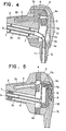
- Figure 4 is a detailed cross sectional view of the embodiment of Figure 2;
- Figure 5 is a detailed cross sectional view of the embodiment of Figure 3:
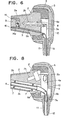
- Figure 6 is a cross sectional view of a still further embodiment of the invention;
- Figure 7 is a cross sectional view of the ear microphone as shown in Figure 4 taken along the line VII-VII;
- Figure 8 is a cross sectional view of still a further embodiment of the invention;
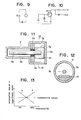
- Figures 9 and 10 show equivalent circuits using electret type converter elements;
- Figure 11 is an enlarged sectional view of the electret type converter element;
- Figure 12 is a cross sectional view taken along the line XII-XII of Figure 11 and rotated 90°;
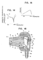
- Figure 13 is a diagram showing the frequency characteristics of a bone-conducted vibration and that of a microphone having a predetermined sensitivity to correct for the forementioned characteristics;
- Figure 14 is a diagram showing the frequency characteristics of the piezoelectric type converter element;
- Figure 15 is a diagram showing the frequency characteristics of the electret type converter element of a still further embodiment of the invention; and
- Figure 16 is a cross sectional view of a still further embodiment of the present invention.
- In Figure 1, a
pickup piece 2 is shown having a configuration to facilitate insertion thereof into theexternal auditory canal 1 and formed of rigid material having a relatively large mass such as zinc die castings. Thepickup piece 2 is formed with acavity 2b therein containing a vibration/electricsignal converter element 3. As here embodied theconverter element 3 is a piezoelectric element supported in cantilever fashion. Aresilient member 4 of natural or synthetic rubber is attached to the rear surface of thepickup piece 2. Theresilient member 4 is further affixed to asupport body 5 made of material having a relatively large mass like that of thepickup piece 2, and can be of the same material.Lead wire 3a ofconverter element 3 extends throughpickup piece 2,resilient member 4, and supportbody 5 for connection to transmitter T. The symbol At designates an aerial. - The mass of
pickup piece 2 andsupport body 5 should be large, however, the mass is subject to various limits such as the size of and in particular the diameter of the external auditory canal, the depth and available space therein, and desired comfort when the ear microphone is inserted for a long time. The resiliency ofresilient member 4 must also be large but is subject to limits in view of the required ease of insertion of the ear microphone into the external auditory canal and its required structural strength for a desirable product. Considering these limits as well as the needs of mass production, metal pieces such as zinc die castings having a relatively large specific gravity are preferred forpickup piece 2 andsupport body 5. For theresilient member 4, a material having a large resiliency in three dimensions or in two dimensions normal to the longitudinal axis of the external auditory canal is preferred. A mechanical spring assembly may be employed but natural or synthetic rubber is preferred due to the general small size requirements of the ear microphone. Thelead wire 3a of converter element .3 should be fine and resilient enough not to significantly reduce the resiliency ofresilient member 4. - In operation, the speech of the wearer is conducted to pickup
piece 2 in the form of bone-conducted vibration from the ;external auditory canal. This vibration reachesconverter element 3, where it is converted into an electrical signal which in turn is conducted throughlead wire 3a to the transmitter to be transmitted from the aerial in the form of an electromagnetic wave. - In this situation, vibration conducted from outside through
lead wire 3a is absorbed by a vibration reduction mechanism consisting of the mass ofsupport body 5 and the resiliencies oflead wire 3a andresilient member 4. Vibration directly inflicted uponsupport body 5 is absorbed by another vibration reduction mechanism made up of the mass ofpickup piece 2 and the resiliency ofresilient member 4. In either case, it is desirable that the resonance frequency of each vibration reduction mechanism is below the speech frequency range at which the converter element is designed to be most sensitive. To achieve this objective, the masses ofpickup piece 2 andsupport body 5 are selected to be large while the resiliencies ofresilient body 4 andlead wire 3a are similarly selected to be large. Where the resiliencies of resilient member 4'andlead wire 3 are large, it is found that onlypickup piece 2 is responsible for the effective load of the voice sound signal coming through the external auditory canal with a minimum influence of the mass ofsupport body 5. Therefore the mass of the support body will not adversely effect the voice pick-up sensitivity. - In addition to the above embodiment which performs only as a microphone, an explanation.will be given for two other embodiments which incorporate a speaker and accomplish two-way communication. These embodiments are shown in Figures 2 and 3 in which like numerals designate like members in the Figure 1 embodiment. Therefore, the explanation concerning their function as it relates to the microphone will be omitted to avoid duplication.
- In the embodiment shown in Figure 2, the
numeral 6 designates a sound tube which is formed throughsupport body 5,resilient member 4 andpickup piece 2. Saidsound tube 6 has an opening in the front end ofpickup piece 2 and another opening insupport body 5 to conduct the voice sound fromspeaker 9 into theexternal auditory canal 1. Receiver R is connected to the ear microphone by way ofspeaker 9 andlead wire 9a and the symbol Ar designates an aerial. - In the embodiment of Figure 3,
miniature speaker 9 is installed withinsupport body 5.Sound tube 6 opens at its one end into thespeaker 9 which in turn is connected to receiver R by way oflead wire 9a. - The operation of the embodiments shown in Figures 2 and 3 will now be explained. In the case where these embodiments function as an earphone, external signals received by receiver R are reproduced by
speaker 9 and conducted into the externalauditory canal 1 by way ofsound tube 6. It is preferable in the above embodiments that soundtube 6 be of a material soft enough not to reduce the combined resiliency ofresilient member 4 andlead wire 3a. - The practical design of the embodiment of Figure 2 will be explained referring to the more detailed Figure 4. The
pickup piece 2 is covered with aplastic film coating 2a and is formed withcavity 2b and throughbore 2c therein. A sound tube 6 (or a front tube) extends throughthroughbore 2c and is supported byring damper 7 in resilient fashion relative topickup piece 2. Thesound tube 6 is made of metal having a large mass whereas thering damper 7 is made of material having a large resiliency such as natural or synthetic rubbers. Theconverter element 3, located incavity 2b, is fixed by a fixingmember 3b in a cantilevered position adjacent to shieldplate 8. - The
resilient member 4 is formed of natural or synthetic rubber material having adequate hardness to maintain structural integrity and strength and is formed with acentral cavity 4a. Thesupport body 5 is formed withbore 5a throughwhichsound tube 6 extends.Bushing 11 is inserted intobore 5a into which, in turn, is insertedpipe 12.Pipe 12 andsound tube 6 are connected to each other byresilient tube 6a (or a back tube) and metal pipe6b. Lead wire 3a extending fromconverter element 3 passes through themetal pipe 6b and is led out of the assembly. A plastic covering 10 coverssupport body 5. - Although not shown,
pipe 12 connected to soundtube 6 is connected at its other end to a speaker of the receiver whereaslead wire 3a is connected to the transmitter. - The operation of'this embodiment as a microphone is substantially the same as that of the embodiment of Figure 1. Therefore, the operation as an earphone only will be explained. Signals received by the receiver are reproduced by a speaker and conducted through
pipe 12,metal pipe 6b,resilient tube 6a andsound tube 6 to be transmitted into the external auditory canal. In this situation,sound tube 6 is caused to vibrate by the vibration energy of the sound conducted through thesound tube 6 but the part of the vibration which has a frequency range higher than the resonance frequency, determined by the resiliency ofdamper 7 and the mass ofsound tube 6, is absorbed bysound tube 6 before traveling beyonddamper 7. It is desirable that the resonance frequency is below the speech frequency range to whichconverter element 3 is sensitive. For this purpose, the mass ofsound tube 6 and the resiliency ofdamper 7 are preferably large. - Although
sound tube 6 is supported byring damper 7 made of for instance a natural or synthetic rubber material in the above embodiment, thering damper 7 may be replaced with any resilient material which fills throughbore 2c betweensound tube 6 andpickup piece 2.Lead wire 3a extends in a direction normal to the plane of vibrationof.converter element 3, but it may also extend in other directions including in a plane parallel to the plane of vibration of the converter. - It should be understood that the provision for the speaker outside the ear piece allows for detection by
converter 3 only of the vibration directly conducted from the external auditory canal to pick-uppiece 2. Conduction of the speaker vibrations toconverter element 3 installed within the ear piece is prevented. This reduced acoustic coupling between the speaker and the ear microphone (i) reduces howling in two-way communications using two carrier frequencies and (ii) eliminates erroneous switching action in a single carrier two-way communication incorporating an automatic voice switching system assuring proper switching action by means of the user's voice sound. In the latter type of system the user does not need to operate a transmit/receive button and frees his hands for other activity. - Referring to Figure 7, a cross section of the embodiment of Figure 4 will be explained. The
piezoelectric element 3 andsound tube 6 are contained in substantially the same vertical plane. Thepiezoelectric element 3 is installed inpickup piece 2 to vibrate substantially normally to that plane as shown in Figure 7. In other words,piezoelectric element 3 having, for example, a length of llmm, a width of lmm, and a thickness of 0.6mm is adapted to vibrate in the direction of said thickness whereassound tube 6 extends in the direction of the width of theelement 3. Therefore, possible leakage of vibration fromsound tube 6 will not cause theconverter element 3 to vibrate with the result that such relative positioning of thesound tube 6 and theconverter element 3 reduces acoustic coupling between the speaker and the ear microphone. - The practical design of the embodiment of Figure 3 will be explained referring to the details of Figure 5. This embodiment has substantially the same structure as that of Figure 4. However,
support body 5 hascavity 5a for accommodatingminiature speaker 9 as used in hearing aids. Thespeaker 9 is held in a floating condition byspeaker damper 15 made of material (such as a silicone gel which is capable of maintaining a predetermined configuration) having a large resiliency.Sound tube 6 having a large resiliency is made with a thin wall thickness. Thesound tube 6 is connected at one end to sound transmittingsection 9b ofspeaker 9 and inserted inthroughbore 2c formed inpickup piece 2. Thesound tube 6 is connected to metal pipe 6c at its other end. Metal pipe 6c opens into the external auditory canal. Thesound tube damper 7 is provided withinpickup piece 2 and formed of material having a large resiliency and can be of the same material as that ofdamper 15 ofspeaker 9. Intermediate plate 8a is fixed onsupport body 5.Respective lead wires converter element 3 andspeaker 9 are connected to the intermediate plate 8a and then throughcable 18 to the transmitter and receiver respectively. Thewires support body 5,cable 18 andwires Resilient member 4 betweenpickup piece 2 andsupport body 5 is preferably formed of silicone or urethane rubber having adequate hardness to maintain structural strength. - The operation of this embodiment as a microphone is practically the same as that of the embodiment of Figure 1. Therefore, the operation as an earphone only will be explained. Signals received by the receiver are sent through
cable 18 andlead wire 9a tospeaker 9. When thespeaker 9 is driven, the reproduced sound is transmitted into the external auditory canal throughsound tube 6 and metal pipe 6c. - Any noise vibration conducted through
cable 18 caused by friction betweencable 18 and the user's clothing is primarily absorbed by a first vibration reduction mechanism consisting up of the mass ofsupport body 5 and the resiliency ofcable 18. Noise vibration generated atsupport body 5, for instance by strong wind or the wearer's hair is absorbed by a second vibration reduction mechanism consisting of the resiliency of externalresilient member 4 and the mass ofpickup piece 2. - Further, the vibration caused by driven
speaker 9 is primarily absorbed by a third vibration reduction mechanism consisting of the resiliency ofspeaker damper 15 and the mass ofsupport body 5. Any unabsorbed vibration is further subjected to secondary damping treatment provided by the second vibration reduction mechanism, thus preventing propagation of such noise vibration toconverter element 3. - Vibrations leaking to sound
tube 6 and metal pipe 6c are damped by a fourth vibration reduction mechanism consisting of the mass of metal pipe 6c and resiliencies ofsound tube 6 andsound tube damper 7. The vibration excited by voice sound energy passes through thesound tube 6 and metal pipe 6c and is also absorbed by the fourth vibration reduction mechanism. -
Speaker 9 may be provided in a suspended condition by a thin rubber film which is extended withincavity 5a, instead of being suspended in such resilient material as gel. - The provision of the speaker within the ear microphone as in Figure 5 in a suspended condition-using material having a large resiliency prevents conduction of the speaker vibrations to the converter element installed within the same ear microphone without effecting the detection of vibrations conducted directly from the auditory canal to pick-up
piece 2. - This reduced acoustic coupling between the speaker and the ear microphone eliminates any howling in two-way communication using two carrier frequencies or any erroneous switching action in a single carrier two-way communication incorporating automatic voice switching. Proper switching action is assured by means of the user's voice sound and since no transmit/receive button needs to be pushed, the hands are free for other activity. - Referring to Figure 6, a still further embodiment of the present invention will be explained. The structure is substantially the same as the embodiment shown in Figure 4.
Pickup piece 2 is formed withcavity 2b extending from the rear side thereof toward the front end. The front end ofpickup piece 2 is formed withrecess 14 which is in communication withbore 14a.Lead wire 3a ofconverter element 3 extends throughshield plate 8,cavity 4a formed inresilient member 4 andbushing 11. - A
rubber damper 15 fits intorecess 14. A miniaturemagnetic speaker 9 is accommodated withindamper 15.Lead wire 9a ofspeaker 9 extends fromspeaker 9 throughbore 14a,pickup piece 2,cavity 4a andbushing 11. Although not shown in Figure 6,lead wire 3a extending fromconverter element 3 is connected to a transmitter whilelead wire 9a extending fromspeaker 9 is connected to a receiver. - The operation as a microphone of the device of Figure 6 is substantially the same as that of the embodiment shown in Figure 1. This embodiment functions as an earphone in the following manner. An external signal received by the receiver travels through
lead wire 9a and reaches thespeaker 9.Speaker 9 reproduces voice sound signals which are transmitted into the external auditory canal. Sincespeaker 9 is close to the eardrum, its output may be low and, thus the reduced vibration is more easily damped in the vibration reduction mechanism system consisting fordamper 15 of a highly resilient material andpickup piece 2. This improved acoustic separation between the ear microphone and the speaker provides enhanced operation of a single carrier two-way communication utilizing automatic voice switching system, since no erroneous switching action from the receiving phase to the transmitting phase will take place. - Although an explanation is given with respect to two-way communication utilizing a single carrier frequency in the above embodiment, this embodiment is also applicable to two-way communication utilizing two different carrier frequencies, where the improved acoustic separation assures a system without howling noise.
- Referring now to Figure 8, a still further embodiment of the present invention will be described. This embodiment has substantially the same structure as that of the embodiment shown in Figure 4. The only difference is that
converter element 3 is replaced with an electret type converter element 3'. - Referring to Figures'9 and 10, the operation of the electret type converter element 3' will be explained. Electret type converter element 3' has opposing electrodes (one stationary electrode and one movable electrode) across which a voltage is applied. When bone-conducted vibration reaches converter element 3', the capacitance between the stationary and movable electrodes is varied as a function of the vibrations. As a result, an electrical signal is generated. Since the output of electret 3' has an extremely high impedance, an impedance converting element such as a field effect transistor (FET) is incorporated in this embodiment as shown in Figure 10 to obtain lower impedance.
- Referring to Figures 11 and 12, one example of electret type converter element will be explained. A shield case 3'a has a large diameter section and a small diameter section. Rubber damper 3'b is fixed by damper support 3'c at a point where the large diameter section and the small diameter section are joined. Movable
metal electrode rod 3'd is resiliently journalled by damper 3'b and extends longitudinally within the casing 3'a. Themovable electrode 3'd is connected to lead wire 3'e at a portion thereof where it is journalled by damper 3'b. - Stationary electrode plate 3'f is fixedly provided in the large diameter section of shield case 3'a. Lead wire 3'g is connected to the stationary electrode 3'f. Although not shown, an FET is attached to FET mount 3'h. The 'lead wire 3'e is connected to the source of the FET whereas lead wire 3'g is connected to its gate. The output signal of the FET is sent to the external transmitter through an output lead wire (not shown) of the FET. In the above structure, it is possible to adjust the output level by changing the length and the configuration of
movable electrode 3'd and the location at which the movable electrode is journalled by damper 3'b. It is also possible to determine frequency characteristics by changing the resiliency of damper 3'b and the weight ofmovable electrode 3'd, respectively. - In the operation of the embodiment of Figure 8,
pickup piece 2 inserted into the user's external auditory canal conducts voice sound in the form of bone-conducting vibration to converter element 3', where it is converted into an electrical signal. The electrical signal is sent through the lead wire of the FET over to the transmitter where it is transmitted through the aerial in the form of an electromagnetic wave. - The embodiment of Figure 8 is directed to solving a problem which is created in the ear microphone using a piezoelectric con- verter. An ordinary piezoelectric type converter element supported in cantilever form cannot properly compensate for the propagation loss of the bone-conducted voice sound. Referring to Figure 13, the frequency characteristics of the damped voice is shown on a logarithmic scale, wherein the frequency characteristic a is substantially linear. In order to provide intelligible reproduction, it is desirable to design a microphone having a correcting capability as shown by the line b in Figure 13 where the required frequency range is about 300 to 3,300 hz. However, proper compensation of the frequency characteristic of the ear microphone is difficult with the conventional piezoelectric converter element supported in cantilever form for the following reasons.
- First, compensation is effected in the piezoelectric con- verter element by making use of the gradient of resonance point of the cantilever structure of the converter element. The gradient is, however, so steep that overcompensation will result. This overcompensation gives rise to howling in a two-way communi- cation utilizing two different carrier frequencies or erroneous switchover action if the automatic voice switching system is incorporated in a single carrier two-way communication. The gradient can be made less steep by supporting the root portion of the converter element to a damping body. However, it is - difficult to obtain a proper gradient due to its limited design flexibility.
- Second, the piezoelectric converter element in cantilever form produces a flat frequency characteristic as shown by the line a in Figure 14 at the lower frequency range while the bone-conducted voice level of the lower frequency is emphasized as shown by line b. As a result, the reproduction in the lower frequency range becomes relatively stronger, thus making the reproduced sound less intelligible. Any attempt to make up for the shortcoming by filtering out the lower range makes the whole circuitry even more complex with an increase in the cost.
- An example which does not require any outside filters and still assures adequate and intelligible output levels uses the electret shown in Figure 11. Assuming a
movable electrode 3'd of lmm in diameter, aluminum pipe of 8mm in length, and damper 3'b of butyl rubber having high electrical resistance, an ear microphone with a frequency characteristics as shown in Figure 15 can be achieved. - Although the embodiment shown in Figure 8 employs an external speaker which reproduces voice sound signals to be conducted into the external auditory canal through
sound tube 6, the speaker may be of a built-in type as shown in Figures 5 and 6. Converter element 3' is shown to be installed withincavity 2b in this embodiment. - Referring to Figure 16, a still further embodiment of the invention will be explained. The general structure of the ear microphone is substantially the same as that of the embodiment of Figure 4 except that
support body 5 is formed withrecess 5b in the outside surface thereof and switch 16 is installed by way of printedcircuit board 17. Theswitch 16 is provided betweenlead wire 3a extending fromconverter element 3 andlead wire 16b extending tometal pipe 12. Theswitch 16 employs a known conductive rubber material, wherein its contacts are closed by pressingcontrol section 16a so thatlead wire 3a is shortcircuited. The numeral 10 designates a plastic covering forsupport body 5. The plastic covering 10 has an opening such thatcontrol section 16a projects outward permitting switch operations from the outside. - In operation, pressing of
control section 16a ofswitch 16 closes the contacts to short-circuit lead wire 3a ofconverter element 3. As a result, the output fromconverter element 3 will not be sent to the transmitter. The vibrations resulting from insertion or removal of the ear microphone into or from the external auditory canal are unavoidable. Theswitch 16 prevents noise from such vibrations from being transmitted to the receiving end when the user either inserts the ear microphone or withdraws it. -
Switch 16 need not be restricted to a conductive rubber type and may be replaced with those of other types which permit interruption of the circuit betweenlead wires - The structure of the ear microphone according to the present invention is characterized in that the pickup piece to be inserted into the external auditory canal is affixed to the support body by way of a resilient member, the pickup piece and the support body being of a rigid material having a relatively large mass. As a result, external vibrations conducted through the lead wire and those applied to the support body as well, are absorbed, thus minimizing the generation of noise due to external factors. Moreover, the prevention of noise vibrations due to acoustic cross coupling between receiver and converter element, enables incorporation of an automatic voice switching mechanism into a single carrier two-way voice communication system which is otherwise apt to cause erroneous switching action. As a result, it has become feasible to design a product which can function as a voice communication terminal to be worn by a user in his ear and operated without any the use of the hands. This makes it feasible to design a product which can function as a voice communication terminal for a two-way voice communication system utilizing two carrier frequencies which can be worn in an ear and operated without the use of the hands.
Claims (10)
Applications Claiming Priority (14)
| Application Number | Priority Date | Filing Date | Title |
|---|---|---|---|
| JP57072315A JPS58188993A (en) | 1982-04-27 | 1982-04-27 | Ear microphone |
| JP7231882A JPS58188996A (en) | 1982-04-27 | 1982-04-27 | Two-way communication device in external auditory miatus |
| JP72316/82 | 1982-04-27 | ||
| JP72318/82 | 1982-04-27 | ||
| JP72319/82 | 1982-04-27 | ||
| JP7231682A JPS58188994A (en) | 1982-04-27 | 1982-04-27 | Ear microphone |
| JP72315/82 | 1982-04-27 | ||
| JP72317/82 | 1982-04-27 | ||
| JP7231982A JPS58188997A (en) | 1982-04-27 | 1982-04-27 | Ear microphone |
| JP7231782A JPS58188995A (en) | 1982-04-27 | 1982-04-27 | Ear microphone |
| JP9386182A JPS58210793A (en) | 1982-06-01 | 1982-06-01 | Bi-direction talking device used in external auditory miatus |
| JP93860/82 | 1982-06-01 | ||
| JP93861/82 | 1982-06-01 | ||
| JP9386082A JPS58210792A (en) | 1982-06-01 | 1982-06-01 | Ear microphone |
Publications (3)
| Publication Number | Publication Date |
|---|---|
| EP0092822A2 true EP0092822A2 (en) | 1983-11-02 |
| EP0092822A3 EP0092822A3 (en) | 1985-03-20 |
| EP0092822B1 EP0092822B1 (en) | 1989-07-26 |
Family
ID=27565178
Family Applications (1)
| Application Number | Title | Priority Date | Filing Date |
|---|---|---|---|
| EP83103974A Expired EP0092822B1 (en) | 1982-04-27 | 1983-04-22 | Ear microphone |
Country Status (4)
| Country | Link |
|---|---|
| US (1) | US4588867A (en) |
| EP (1) | EP0092822B1 (en) |
| AU (1) | AU552358B2 (en) |
| DE (1) | DE3380289D1 (en) |
Cited By (25)
| Publication number | Priority date | Publication date | Assignee | Title |
|---|---|---|---|---|
| FR2604589A1 (en) * | 1986-09-25 | 1988-04-01 | Temco Japan | ATRIAL MICROPHONE INCORPORATED INTO AN EARPHONE |
| DE3723261A1 (en) * | 1986-11-10 | 1988-05-11 | Temco Japan | TELEPHONE SET WITH EAR MICROPHONE |
| GB2246015A (en) * | 1990-06-26 | 1992-01-15 | Matsushita Electric Ind Co Ltd | Bone-conduction transducer |
| WO1994010818A1 (en) * | 1992-11-02 | 1994-05-11 | Lourens George Bordewijk | Sound amplification system |
| GB2281004A (en) * | 1993-08-11 | 1995-02-15 | Yang Chao Ming | Combined microphone/earphone |
| FR2755561A1 (en) * | 1996-11-07 | 1998-05-07 | Neill Andre O | Voice collecting microphone capsule for hands-free telephone |
| GB2373667A (en) * | 2000-12-08 | 2002-09-25 | Richard Potter | In ear communications over-volume protection |
| EP2208367A1 (en) * | 2007-10-12 | 2010-07-21 | Earlens Corporation | Multifunction system and method for integrated hearing and communiction with noise cancellation and feedback management |
| US9049528B2 (en) | 2008-06-17 | 2015-06-02 | Earlens Corporation | Optical electro-mechanical hearing devices with combined power and signal architectures |
| US9154891B2 (en) | 2005-05-03 | 2015-10-06 | Earlens Corporation | Hearing system having improved high frequency response |
| US9392377B2 (en) | 2010-12-20 | 2016-07-12 | Earlens Corporation | Anatomically customized ear canal hearing apparatus |
| US9591409B2 (en) | 2008-06-17 | 2017-03-07 | Earlens Corporation | Optical electro-mechanical hearing devices with separate power and signal components |
| US9749758B2 (en) | 2008-09-22 | 2017-08-29 | Earlens Corporation | Devices and methods for hearing |
| US9924276B2 (en) | 2014-11-26 | 2018-03-20 | Earlens Corporation | Adjustable venting for hearing instruments |
| US9930458B2 (en) | 2014-07-14 | 2018-03-27 | Earlens Corporation | Sliding bias and peak limiting for optical hearing devices |
| US10034103B2 (en) | 2014-03-18 | 2018-07-24 | Earlens Corporation | High fidelity and reduced feedback contact hearing apparatus and methods |
| US10178483B2 (en) | 2015-12-30 | 2019-01-08 | Earlens Corporation | Light based hearing systems, apparatus, and methods |
| US10292601B2 (en) | 2015-10-02 | 2019-05-21 | Earlens Corporation | Wearable customized ear canal apparatus |
| US10492010B2 (en) | 2015-12-30 | 2019-11-26 | Earlens Corporations | Damping in contact hearing systems |
| EP3614699A1 (en) * | 2018-08-24 | 2020-02-26 | Sivantos Pte. Ltd. | Hearing aid with a coupling unit for vibration-damped mounting of a hearing aid |
| US11102594B2 (en) | 2016-09-09 | 2021-08-24 | Earlens Corporation | Contact hearing systems, apparatus and methods |
| US11166114B2 (en) | 2016-11-15 | 2021-11-02 | Earlens Corporation | Impression procedure |
| US11212626B2 (en) | 2018-04-09 | 2021-12-28 | Earlens Corporation | Dynamic filter |
| US11350226B2 (en) | 2015-12-30 | 2022-05-31 | Earlens Corporation | Charging protocol for rechargeable hearing systems |
| US11516603B2 (en) | 2018-03-07 | 2022-11-29 | Earlens Corporation | Contact hearing device and retention structure materials |
Families Citing this family (200)
| Publication number | Priority date | Publication date | Assignee | Title |
|---|---|---|---|---|
| CA1165248A (en) * | 1980-10-31 | 1984-04-10 | Shingo Watanabe | Electro-acoustic transducer |
| JPS60103798A (en) * | 1983-11-09 | 1985-06-08 | Takeshi Yoshii | Displacement-type bone conduction microphone |
| US4729451A (en) * | 1984-05-30 | 1988-03-08 | Beltone Electronics, Corporation | Receiver suspension and acoustic porting system |
| US4696045A (en) * | 1985-06-04 | 1987-09-22 | Acr Electronics | Ear microphone |
| US4720857A (en) * | 1985-12-06 | 1988-01-19 | Plantronics, Inc. | Miniaturized headset for two-way voice communication |
| US4930156A (en) * | 1988-11-18 | 1990-05-29 | Norcom Electronics Corporation | Telephone receiver transmitter device |
| US5109410A (en) * | 1990-01-05 | 1992-04-28 | Technology Management And Ventures, Ltd. | Two-line, hands-free telephone system |
| US5164984A (en) * | 1990-01-05 | 1992-11-17 | Technology Management And Ventures, Ltd. | Hands-free telephone assembly |
| US5282253A (en) * | 1991-02-26 | 1994-01-25 | Pan Communications, Inc. | Bone conduction microphone mount |
| US5295193A (en) * | 1992-01-22 | 1994-03-15 | Hiroshi Ono | Device for picking up bone-conducted sound in external auditory meatus and communication device using the same |
| US5280524A (en) * | 1992-05-11 | 1994-01-18 | Jabra Corporation | Bone conductive ear microphone and method |
| US5373555A (en) * | 1992-05-11 | 1994-12-13 | Jabra Corporation | Unidirectional ear microphone and gasket |
| CA2134884C (en) * | 1992-05-11 | 2004-11-23 | Elwood G. Norris | Unidirectional ear microphone and method |
| US5812659A (en) * | 1992-05-11 | 1998-09-22 | Jabra Corporation | Ear microphone with enhanced sensitivity |
| US5426719A (en) * | 1992-08-31 | 1995-06-20 | The United States Of America As Represented By The Department Of Health And Human Services | Ear based hearing protector/communication system |
| US5909498A (en) * | 1993-03-25 | 1999-06-01 | Smith; Jerry R. | Transducer device for use with communication apparatus |
| JPH09172479A (en) * | 1995-12-20 | 1997-06-30 | Yokoi Kikaku:Kk | Transmitter-receiver and speaker using it |
| US5768397A (en) * | 1996-08-22 | 1998-06-16 | Siemens Hearing Instruments, Inc. | Hearing aid and system for use with cellular telephones |
| US6175633B1 (en) | 1997-04-09 | 2001-01-16 | Cavcom, Inc. | Radio communications apparatus with attenuating ear pieces for high noise environments |
| US6176576B1 (en) | 1997-06-06 | 2001-01-23 | Radians, Inc. | Eyewear supported by a wearer's concha of an ear |
| US6920229B2 (en) * | 1999-05-10 | 2005-07-19 | Peter V. Boesen | Earpiece with an inertial sensor |
| US6542721B2 (en) | 1999-10-11 | 2003-04-01 | Peter V. Boesen | Cellular telephone, personal digital assistant and pager unit |
| US6094492A (en) | 1999-05-10 | 2000-07-25 | Boesen; Peter V. | Bone conduction voice transmission apparatus and system |
| US6823195B1 (en) | 2000-06-30 | 2004-11-23 | Peter V. Boesen | Ultra short range communication with sensing device and method |
| US6952483B2 (en) * | 1999-05-10 | 2005-10-04 | Genisus Systems, Inc. | Voice transmission apparatus with UWB |
| US20020057810A1 (en) * | 1999-05-10 | 2002-05-16 | Boesen Peter V. | Computer and voice communication unit with handsfree device |
| US6738485B1 (en) | 1999-05-10 | 2004-05-18 | Peter V. Boesen | Apparatus, method and system for ultra short range communication |
| US6560468B1 (en) * | 1999-05-10 | 2003-05-06 | Peter V. Boesen | Cellular telephone, personal digital assistant, and pager unit with capability of short range radio frequency transmissions |
| US7508411B2 (en) * | 1999-10-11 | 2009-03-24 | S.P. Technologies Llp | Personal communications device |
| US6852084B1 (en) * | 2000-04-28 | 2005-02-08 | Peter V. Boesen | Wireless physiological pressure sensor and transmitter with capability of short range radio frequency transmissions |
| US6694180B1 (en) | 1999-10-11 | 2004-02-17 | Peter V. Boesen | Wireless biopotential sensing device and method with capability of short-range radio frequency transmission and reception |
| JP2001125576A (en) * | 1999-10-22 | 2001-05-11 | Citizen Electronics Co Ltd | Sound producing body and electonic apparatus mounted with sound producing body |
| US6741718B1 (en) | 2000-08-28 | 2004-05-25 | Gn Jabra Corporation | Near-field speaker/microphone acoustic/seismic dampening communication device |
| US20040204170A1 (en) * | 2002-05-01 | 2004-10-14 | Mkhitarian Harry A. | Mobile phone battery pack and battery cover with earphone-microphone earpiece jack |
| US20040141628A1 (en) * | 2003-01-17 | 2004-07-22 | Fellowes, Inc. | Earpiece with interchangeable end portion |
| JP2004266321A (en) * | 2003-01-22 | 2004-09-24 | Hitachi Maxell Ltd | Ear installation-type calling device |
| JP2005277792A (en) * | 2004-03-25 | 2005-10-06 | Nappu Enterprise Kk | Oscillation/echo canceller system |
| US7899194B2 (en) * | 2005-10-14 | 2011-03-01 | Boesen Peter V | Dual ear voice communication device |
| US8526646B2 (en) * | 2004-05-10 | 2013-09-03 | Peter V. Boesen | Communication device |
| US7302071B2 (en) * | 2004-09-15 | 2007-11-27 | Schumaier Daniel R | Bone conduction hearing assistance device |
| FI20041625A (en) * | 2004-12-17 | 2006-06-18 | Nokia Corp | A method for converting an ear canal signal, an ear canal converter, and a headset |
| CN1874613A (en) * | 2005-03-25 | 2006-12-06 | 南承铉 | Automatic control earphone system using capacitance sensor |
| CH699444B1 (en) * | 2006-10-11 | 2010-03-15 | Phonak Ag | Hearing aid. |
| US20080170734A1 (en) * | 2007-01-16 | 2008-07-17 | Miklos Major | Sound transmitting device |
| USD596616S1 (en) | 2008-09-05 | 2009-07-21 | Apple Inc. | Earphone |
| US20100104126A1 (en) * | 2008-10-24 | 2010-04-29 | Andrea Martina Greene | Tangle resistant audio cord and earphones |
| US8213645B2 (en) * | 2009-03-27 | 2012-07-03 | Motorola Mobility, Inc. | Bone conduction assembly for communication headsets |
| JP4734441B2 (en) * | 2009-06-12 | 2011-07-27 | 株式会社東芝 | Electroacoustic transducer |
| US8737669B2 (en) * | 2011-07-28 | 2014-05-27 | Bose Corporation | Earpiece passive noise attenuating |
| US8638971B2 (en) * | 2011-09-30 | 2014-01-28 | Apple Inc. | Open-air earbuds and methods for making the same |
| USD710326S1 (en) * | 2013-04-15 | 2014-08-05 | Verto Medical Solutions, LLC | Wireless headphones |
| USD733101S1 (en) * | 2014-01-02 | 2015-06-30 | Google Technology Holdings LLC | Pair of earbuds |
| JP1526035S (en) * | 2014-03-31 | 2015-06-15 | ||
| USD738863S1 (en) | 2014-05-19 | 2015-09-15 | Amazon Technologies, Inc. | Earphones |
| TWD176083S (en) * | 2014-12-29 | 2016-06-01 | 三星電子股份有限公司 | Portion of earphone |
| USD780157S1 (en) * | 2015-04-21 | 2017-02-28 | Zound Industries International Ab | In ear headphone |
| USD764436S1 (en) * | 2015-04-24 | 2016-08-23 | Bose Corporation | Headphones |
| US9905088B2 (en) | 2015-08-29 | 2018-02-27 | Bragi GmbH | Responsive visual communication system and method |
| US9755704B2 (en) | 2015-08-29 | 2017-09-05 | Bragi GmbH | Multimodal communication system induction and radio and method |
| US10194232B2 (en) | 2015-08-29 | 2019-01-29 | Bragi GmbH | Responsive packaging system for managing display actions |
| US9800966B2 (en) | 2015-08-29 | 2017-10-24 | Bragi GmbH | Smart case power utilization control system and method |
| US9866282B2 (en) | 2015-08-29 | 2018-01-09 | Bragi GmbH | Magnetic induction antenna for use in a wearable device |
| US10122421B2 (en) | 2015-08-29 | 2018-11-06 | Bragi GmbH | Multimodal communication system using induction and radio and method |
| US9843853B2 (en) | 2015-08-29 | 2017-12-12 | Bragi GmbH | Power control for battery powered personal area network device system and method |
| US10194228B2 (en) | 2015-08-29 | 2019-01-29 | Bragi GmbH | Load balancing to maximize device function in a personal area network device system and method |
| US10234133B2 (en) | 2015-08-29 | 2019-03-19 | Bragi GmbH | System and method for prevention of LED light spillage |
| US9972895B2 (en) | 2015-08-29 | 2018-05-15 | Bragi GmbH | Antenna for use in a wearable device |
| US10409394B2 (en) | 2015-08-29 | 2019-09-10 | Bragi GmbH | Gesture based control system based upon device orientation system and method |
| US9854372B2 (en) | 2015-08-29 | 2017-12-26 | Bragi GmbH | Production line PCB serial programming and testing method and system |
| US9949013B2 (en) | 2015-08-29 | 2018-04-17 | Bragi GmbH | Near field gesture control system and method |
| US9813826B2 (en) | 2015-08-29 | 2017-11-07 | Bragi GmbH | Earpiece with electronic environmental sound pass-through system |
| US9949008B2 (en) | 2015-08-29 | 2018-04-17 | Bragi GmbH | Reproduction of ambient environmental sound for acoustic transparency of ear canal device system and method |
| US10203773B2 (en) | 2015-08-29 | 2019-02-12 | Bragi GmbH | Interactive product packaging system and method |
| US9401158B1 (en) | 2015-09-14 | 2016-07-26 | Knowles Electronics, Llc | Microphone signal fusion |
| US10453450B2 (en) | 2015-10-20 | 2019-10-22 | Bragi GmbH | Wearable earpiece voice command control system and method |
| US10104458B2 (en) | 2015-10-20 | 2018-10-16 | Bragi GmbH | Enhanced biometric control systems for detection of emergency events system and method |
| US10206042B2 (en) | 2015-10-20 | 2019-02-12 | Bragi GmbH | 3D sound field using bilateral earpieces system and method |
| US20170111723A1 (en) | 2015-10-20 | 2017-04-20 | Bragi GmbH | Personal Area Network Devices System and Method |
| US9866941B2 (en) | 2015-10-20 | 2018-01-09 | Bragi GmbH | Multi-point multiple sensor array for data sensing and processing system and method |
| US10506322B2 (en) | 2015-10-20 | 2019-12-10 | Bragi GmbH | Wearable device onboard applications system and method |
| US10175753B2 (en) | 2015-10-20 | 2019-01-08 | Bragi GmbH | Second screen devices utilizing data from ear worn device system and method |
| US9980189B2 (en) | 2015-10-20 | 2018-05-22 | Bragi GmbH | Diversity bluetooth system and method |
| CN105245984B (en) * | 2015-10-26 | 2018-01-19 | 苏州登堡电子科技有限公司 | Cylindrical contact formula microphone |
| US10635385B2 (en) | 2015-11-13 | 2020-04-28 | Bragi GmbH | Method and apparatus for interfacing with wireless earpieces |
| US9944295B2 (en) | 2015-11-27 | 2018-04-17 | Bragi GmbH | Vehicle with wearable for identifying role of one or more users and adjustment of user settings |
| US9978278B2 (en) | 2015-11-27 | 2018-05-22 | Bragi GmbH | Vehicle to vehicle communications using ear pieces |
| US10099636B2 (en) | 2015-11-27 | 2018-10-16 | Bragi GmbH | System and method for determining a user role and user settings associated with a vehicle |
| US10104460B2 (en) | 2015-11-27 | 2018-10-16 | Bragi GmbH | Vehicle with interaction between entertainment systems and wearable devices |
| US10040423B2 (en) | 2015-11-27 | 2018-08-07 | Bragi GmbH | Vehicle with wearable for identifying one or more vehicle occupants |
| US10542340B2 (en) | 2015-11-30 | 2020-01-21 | Bragi GmbH | Power management for wireless earpieces |
| US10099374B2 (en) | 2015-12-01 | 2018-10-16 | Bragi GmbH | Robotic safety using wearables |
| JP1556458S (en) * | 2015-12-04 | 2016-08-15 | ||
| US9980033B2 (en) | 2015-12-21 | 2018-05-22 | Bragi GmbH | Microphone natural speech capture voice dictation system and method |
| US9939891B2 (en) | 2015-12-21 | 2018-04-10 | Bragi GmbH | Voice dictation systems using earpiece microphone system and method |
| US10575083B2 (en) | 2015-12-22 | 2020-02-25 | Bragi GmbH | Near field based earpiece data transfer system and method |
| US10206052B2 (en) | 2015-12-22 | 2019-02-12 | Bragi GmbH | Analytical determination of remote battery temperature through distributed sensor array system and method |
| US10154332B2 (en) | 2015-12-29 | 2018-12-11 | Bragi GmbH | Power management for wireless earpieces utilizing sensor measurements |
| US10334345B2 (en) | 2015-12-29 | 2019-06-25 | Bragi GmbH | Notification and activation system utilizing onboard sensors of wireless earpieces |
| US9779716B2 (en) | 2015-12-30 | 2017-10-03 | Knowles Electronics, Llc | Occlusion reduction and active noise reduction based on seal quality |
| US9830930B2 (en) | 2015-12-30 | 2017-11-28 | Knowles Electronics, Llc | Voice-enhanced awareness mode |
| USD783578S1 (en) * | 2015-12-30 | 2017-04-11 | Oculus Vr, Llc | Earbud |
| USD813849S1 (en) * | 2016-01-13 | 2018-03-27 | Urbanista AB | Headphone |
| US10200790B2 (en) | 2016-01-15 | 2019-02-05 | Bragi GmbH | Earpiece with cellular connectivity |
| US10129620B2 (en) | 2016-01-25 | 2018-11-13 | Bragi GmbH | Multilayer approach to hydrophobic and oleophobic system and method |
| US10104486B2 (en) | 2016-01-25 | 2018-10-16 | Bragi GmbH | In-ear sensor calibration and detecting system and method |
| US9812149B2 (en) | 2016-01-28 | 2017-11-07 | Knowles Electronics, Llc | Methods and systems for providing consistency in noise reduction during speech and non-speech periods |
| US10085091B2 (en) | 2016-02-09 | 2018-09-25 | Bragi GmbH | Ambient volume modification through environmental microphone feedback loop system and method |
| US10667033B2 (en) | 2016-03-02 | 2020-05-26 | Bragi GmbH | Multifactorial unlocking function for smart wearable device and method |
| US10327082B2 (en) | 2016-03-02 | 2019-06-18 | Bragi GmbH | Location based tracking using a wireless earpiece device, system, and method |
| US10085082B2 (en) | 2016-03-11 | 2018-09-25 | Bragi GmbH | Earpiece with GPS receiver |
| US10045116B2 (en) | 2016-03-14 | 2018-08-07 | Bragi GmbH | Explosive sound pressure level active noise cancellation utilizing completely wireless earpieces system and method |
| US10052065B2 (en) | 2016-03-23 | 2018-08-21 | Bragi GmbH | Earpiece life monitor with capability of automatic notification system and method |
| US10856809B2 (en) | 2016-03-24 | 2020-12-08 | Bragi GmbH | Earpiece with glucose sensor and system |
| US10334346B2 (en) | 2016-03-24 | 2019-06-25 | Bragi GmbH | Real-time multivariable biometric analysis and display system and method |
| US11799852B2 (en) | 2016-03-29 | 2023-10-24 | Bragi GmbH | Wireless dongle for communications with wireless earpieces |
| USD819438S1 (en) | 2016-04-07 | 2018-06-05 | Bragi GmbH | Package |
| USD821970S1 (en) | 2016-04-07 | 2018-07-03 | Bragi GmbH | Wearable device charger |
| USD805060S1 (en) | 2016-04-07 | 2017-12-12 | Bragi GmbH | Earphone |
| USD823835S1 (en) | 2016-04-07 | 2018-07-24 | Bragi GmbH | Earphone |
| US10015579B2 (en) | 2016-04-08 | 2018-07-03 | Bragi GmbH | Audio accelerometric feedback through bilateral ear worn device system and method |
| US10747337B2 (en) | 2016-04-26 | 2020-08-18 | Bragi GmbH | Mechanical detection of a touch movement using a sensor and a special surface pattern system and method |
| US10013542B2 (en) | 2016-04-28 | 2018-07-03 | Bragi GmbH | Biometric interface system and method |
| USD824371S1 (en) | 2016-05-06 | 2018-07-31 | Bragi GmbH | Headphone |
| USD836089S1 (en) | 2016-05-06 | 2018-12-18 | Bragi GmbH | Headphone |
| US10582328B2 (en) | 2016-07-06 | 2020-03-03 | Bragi GmbH | Audio response based on user worn microphones to direct or adapt program responses system and method |
| US10216474B2 (en) | 2016-07-06 | 2019-02-26 | Bragi GmbH | Variable computing engine for interactive media based upon user biometrics |
| US10045110B2 (en) | 2016-07-06 | 2018-08-07 | Bragi GmbH | Selective sound field environment processing system and method |
| US10201309B2 (en) | 2016-07-06 | 2019-02-12 | Bragi GmbH | Detection of physiological data using radar/lidar of wireless earpieces |
| US10555700B2 (en) | 2016-07-06 | 2020-02-11 | Bragi GmbH | Combined optical sensor for audio and pulse oximetry system and method |
| US10888039B2 (en) | 2016-07-06 | 2021-01-05 | Bragi GmbH | Shielded case for wireless earpieces |
| US11085871B2 (en) | 2016-07-06 | 2021-08-10 | Bragi GmbH | Optical vibration detection system and method |
| US10158934B2 (en) | 2016-07-07 | 2018-12-18 | Bragi GmbH | Case for multiple earpiece pairs |
| US10165350B2 (en) | 2016-07-07 | 2018-12-25 | Bragi GmbH | Earpiece with app environment |
| US10621583B2 (en) | 2016-07-07 | 2020-04-14 | Bragi GmbH | Wearable earpiece multifactorial biometric analysis system and method |
| US10516930B2 (en) | 2016-07-07 | 2019-12-24 | Bragi GmbH | Comparative analysis of sensors to control power status for wireless earpieces |
| US10587943B2 (en) | 2016-07-09 | 2020-03-10 | Bragi GmbH | Earpiece with wirelessly recharging battery |
| US10397686B2 (en) | 2016-08-15 | 2019-08-27 | Bragi GmbH | Detection of movement adjacent an earpiece device |
| US10977348B2 (en) | 2016-08-24 | 2021-04-13 | Bragi GmbH | Digital signature using phonometry and compiled biometric data system and method |
| US10409091B2 (en) | 2016-08-25 | 2019-09-10 | Bragi GmbH | Wearable with lenses |
| US10104464B2 (en) | 2016-08-25 | 2018-10-16 | Bragi GmbH | Wireless earpiece and smart glasses system and method |
| US11200026B2 (en) | 2016-08-26 | 2021-12-14 | Bragi GmbH | Wireless earpiece with a passive virtual assistant |
| US10887679B2 (en) | 2016-08-26 | 2021-01-05 | Bragi GmbH | Earpiece for audiograms |
| US11086593B2 (en) | 2016-08-26 | 2021-08-10 | Bragi GmbH | Voice assistant for wireless earpieces |
| US10313779B2 (en) | 2016-08-26 | 2019-06-04 | Bragi GmbH | Voice assistant system for wireless earpieces |
| US10200780B2 (en) | 2016-08-29 | 2019-02-05 | Bragi GmbH | Method and apparatus for conveying battery life of wireless earpiece |
| US11490858B2 (en) | 2016-08-31 | 2022-11-08 | Bragi GmbH | Disposable sensor array wearable device sleeve system and method |
| USD822645S1 (en) | 2016-09-03 | 2018-07-10 | Bragi GmbH | Headphone |
| US10598506B2 (en) | 2016-09-12 | 2020-03-24 | Bragi GmbH | Audio navigation using short range bilateral earpieces |
| US10580282B2 (en) | 2016-09-12 | 2020-03-03 | Bragi GmbH | Ear based contextual environment and biometric pattern recognition system and method |
| US10852829B2 (en) | 2016-09-13 | 2020-12-01 | Bragi GmbH | Measurement of facial muscle EMG potentials for predictive analysis using a smart wearable system and method |
| US10516281B2 (en) | 2016-09-21 | 2019-12-24 | Otter Products, Llc | Charging apparatus for wireless earphone |
| US11283742B2 (en) | 2016-09-27 | 2022-03-22 | Bragi GmbH | Audio-based social media platform |
| US10460095B2 (en) | 2016-09-30 | 2019-10-29 | Bragi GmbH | Earpiece with biometric identifiers |
| US10049184B2 (en) | 2016-10-07 | 2018-08-14 | Bragi GmbH | Software application transmission via body interface using a wearable device in conjunction with removable body sensor arrays system and method |
| JP1593736S (en) * | 2016-10-10 | 2017-12-25 | ||
| CN106454591B (en) * | 2016-10-19 | 2020-06-12 | 歌尔股份有限公司 | Earphone set |
| US10942701B2 (en) | 2016-10-31 | 2021-03-09 | Bragi GmbH | Input and edit functions utilizing accelerometer based earpiece movement system and method |
| US10771877B2 (en) | 2016-10-31 | 2020-09-08 | Bragi GmbH | Dual earpieces for same ear |
| US10698983B2 (en) | 2016-10-31 | 2020-06-30 | Bragi GmbH | Wireless earpiece with a medical engine |
| US10455313B2 (en) | 2016-10-31 | 2019-10-22 | Bragi GmbH | Wireless earpiece with force feedback |
| US10117604B2 (en) | 2016-11-02 | 2018-11-06 | Bragi GmbH | 3D sound positioning with distributed sensors |
| US10617297B2 (en) | 2016-11-02 | 2020-04-14 | Bragi GmbH | Earpiece with in-ear electrodes |
| US10205814B2 (en) | 2016-11-03 | 2019-02-12 | Bragi GmbH | Wireless earpiece with walkie-talkie functionality |
| US10225638B2 (en) | 2016-11-03 | 2019-03-05 | Bragi GmbH | Ear piece with pseudolite connectivity |
| US10821361B2 (en) | 2016-11-03 | 2020-11-03 | Bragi GmbH | Gaming with earpiece 3D audio |
| US10062373B2 (en) | 2016-11-03 | 2018-08-28 | Bragi GmbH | Selective audio isolation from body generated sound system and method |
| US10058282B2 (en) | 2016-11-04 | 2018-08-28 | Bragi GmbH | Manual operation assistance with earpiece with 3D sound cues |
| US10045117B2 (en) | 2016-11-04 | 2018-08-07 | Bragi GmbH | Earpiece with modified ambient environment over-ride function |
| US10063957B2 (en) | 2016-11-04 | 2018-08-28 | Bragi GmbH | Earpiece with source selection within ambient environment |
| US10045112B2 (en) | 2016-11-04 | 2018-08-07 | Bragi GmbH | Earpiece with added ambient environment |
| US10506327B2 (en) | 2016-12-27 | 2019-12-10 | Bragi GmbH | Ambient environmental sound field manipulation based on user defined voice and audio recognition pattern analysis system and method |
| US10405081B2 (en) | 2017-02-08 | 2019-09-03 | Bragi GmbH | Intelligent wireless headset system |
| USD836598S1 (en) * | 2017-02-15 | 2018-12-25 | Shenzhen Wahching Technology Co., Ltd | Wireless sport earphones |
| US10582290B2 (en) | 2017-02-21 | 2020-03-03 | Bragi GmbH | Earpiece with tap functionality |
| US10771881B2 (en) | 2017-02-27 | 2020-09-08 | Bragi GmbH | Earpiece with audio 3D menu |
| US11380430B2 (en) | 2017-03-22 | 2022-07-05 | Bragi GmbH | System and method for populating electronic medical records with wireless earpieces |
| US11694771B2 (en) | 2017-03-22 | 2023-07-04 | Bragi GmbH | System and method for populating electronic health records with wireless earpieces |
| US11544104B2 (en) | 2017-03-22 | 2023-01-03 | Bragi GmbH | Load sharing between wireless earpieces |
| US10575086B2 (en) | 2017-03-22 | 2020-02-25 | Bragi GmbH | System and method for sharing wireless earpieces |
| US10708699B2 (en) | 2017-05-03 | 2020-07-07 | Bragi GmbH | Hearing aid with added functionality |
| US11116415B2 (en) | 2017-06-07 | 2021-09-14 | Bragi GmbH | Use of body-worn radar for biometric measurements, contextual awareness and identification |
| US11013445B2 (en) | 2017-06-08 | 2021-05-25 | Bragi GmbH | Wireless earpiece with transcranial stimulation |
| US10344960B2 (en) | 2017-09-19 | 2019-07-09 | Bragi GmbH | Wireless earpiece controlled medical headlight |
| US11272367B2 (en) | 2017-09-20 | 2022-03-08 | Bragi GmbH | Wireless earpieces for hub communications |
| USD851061S1 (en) | 2017-10-16 | 2019-06-11 | Gn Audio A/S | Headset |
| USD870694S1 (en) * | 2017-12-28 | 2019-12-24 | Sony Corporation | Earphone |
| USD860165S1 (en) * | 2017-12-28 | 2019-09-17 | Sony Corporation | Earphone |
| USD871365S1 (en) | 2017-12-28 | 2019-12-31 | Sony Corporation | Earphone |
| USD855581S1 (en) * | 2018-01-17 | 2019-08-06 | Lindero Electronics Co., Ltd. | Wireless earphone |
| USD853359S1 (en) * | 2018-01-25 | 2019-07-09 | Yong Guo | Housing for high-fidelity earbud |
| USD861647S1 (en) * | 2018-09-13 | 2019-10-01 | Shenzhen Zheng He Wei Ye Technology Co., Ltd. | Wireless earphone |
| USD875071S1 (en) * | 2018-10-15 | 2020-02-11 | Shenzhen Aukey Smart Information Technology Co., Ltd. | Headset for telephones |
| JP1646410S (en) * | 2019-01-02 | 2019-11-25 | ||
| USD907606S1 (en) * | 2019-05-05 | 2021-01-12 | Shenzhen Enle Industrial Co., Ltd. | Earphone |
| USD906297S1 (en) | 2019-09-13 | 2020-12-29 | Apple Inc. | Pair of earphones |
| US11036465B2 (en) | 2019-10-28 | 2021-06-15 | Bose Corporation | Sleep detection system for wearable audio device |
| US11477562B2 (en) | 2020-04-18 | 2022-10-18 | Ballast Technology Llc | Wireless headphone charging system |
| USD894875S1 (en) * | 2020-05-24 | 2020-09-01 | Shenzhen Taifeitong Technology Co., Ltd. | Earphones |
| USD921615S1 (en) * | 2020-08-06 | 2021-06-08 | Shen Zhen Ocen Technology Co. Ltd | Earphone |
| EP4247010A1 (en) * | 2022-03-15 | 2023-09-20 | Starkey Laboratories, Inc. | Hearing device |
Citations (4)
| Publication number | Priority date | Publication date | Assignee | Title |
|---|---|---|---|---|
| US3258533A (en) * | 1962-10-16 | 1966-06-28 | Spacelabs Inc | Ear-insert microphone |
| US3550071A (en) * | 1968-05-10 | 1970-12-22 | Krupp Gmbh | Transducer system |
| US4150262A (en) * | 1974-11-18 | 1979-04-17 | Hiroshi Ono | Piezoelectric bone conductive in ear voice sounds transmitting and receiving apparatus |
| FR2455820A1 (en) * | 1979-05-04 | 1980-11-28 | Gen Engineering Co | WIRELESS TRANSMITTING AND RECEIVING DEVICE USING AN EAR MICROPHONE |
Family Cites Families (15)
| Publication number | Priority date | Publication date | Assignee | Title |
|---|---|---|---|---|
| DE915826C (en) * | 1948-10-02 | 1954-07-29 | Atlas Werke Ag | Bone conduction hearing aids |
| US3448224A (en) * | 1966-10-27 | 1969-06-03 | Dictograph Products Inc | Rigid in-the-ear hearing aid |
| US3602330A (en) * | 1970-06-01 | 1971-08-31 | Rubein V Johnson | Acoustic ear mold for hearing aid |
| US3688863A (en) * | 1971-10-08 | 1972-09-05 | Rubein V Johnson | Acoustic ear mold for hearing aid |
| US3944018A (en) * | 1974-08-01 | 1976-03-16 | Rodney Jene Satory | Acoustical seal |
| US4025734A (en) * | 1976-07-27 | 1977-05-24 | Harry Aloupis | Ambient noise shielded ear transceiver |
| US4064362A (en) * | 1976-09-13 | 1977-12-20 | David Richard Williams | Hearing protector |
| DE2759186A1 (en) * | 1977-12-31 | 1979-07-12 | Weltin Optac | Microphone detecting spoken information - is positioned inside human ear to receive sounds from body directly and is acoustically insulated from outside |
| US4156118A (en) * | 1978-04-10 | 1979-05-22 | Hargrave Frances E | Audiometric headset |
| JPS5690000A (en) * | 1979-12-24 | 1981-07-21 | Taiyo Chuki Kk | Longitudinal blast |
| JPS56122245A (en) * | 1980-02-29 | 1981-09-25 | Pilot Pen Co Ltd:The | Automatic control system for transmission or recording and transmission and reception |
| JPS56152395A (en) * | 1980-04-24 | 1981-11-25 | Gen Eng:Kk | Ear microphone of simultaneous transmitting and receiving type |
| US4335281A (en) * | 1980-06-24 | 1982-06-15 | Plantronics, Inc. | Post-auricle contoured headset for two-way voice communication |
| US4407389A (en) * | 1981-01-19 | 1983-10-04 | Johnson Rubein V | Vented acoustic ear mold for hearing aids |
| NL8101286A (en) * | 1981-03-17 | 1982-10-18 | Philips Nv | IMPROVED SUSPENSION FOR A PHONE IN A HEARING AID. |
-
1982
- 1982-09-29 US US06/428,017 patent/US4588867A/en not_active Expired - Fee Related
-
1983
- 1983-04-22 EP EP83103974A patent/EP0092822B1/en not_active Expired
- 1983-04-22 AU AU13859/83A patent/AU552358B2/en not_active Ceased
- 1983-04-22 DE DE8383103974T patent/DE3380289D1/en not_active Expired
Patent Citations (4)
| Publication number | Priority date | Publication date | Assignee | Title |
|---|---|---|---|---|
| US3258533A (en) * | 1962-10-16 | 1966-06-28 | Spacelabs Inc | Ear-insert microphone |
| US3550071A (en) * | 1968-05-10 | 1970-12-22 | Krupp Gmbh | Transducer system |
| US4150262A (en) * | 1974-11-18 | 1979-04-17 | Hiroshi Ono | Piezoelectric bone conductive in ear voice sounds transmitting and receiving apparatus |
| FR2455820A1 (en) * | 1979-05-04 | 1980-11-28 | Gen Engineering Co | WIRELESS TRANSMITTING AND RECEIVING DEVICE USING AN EAR MICROPHONE |
Cited By (69)
| Publication number | Priority date | Publication date | Assignee | Title |
|---|---|---|---|---|
| FR2604589A1 (en) * | 1986-09-25 | 1988-04-01 | Temco Japan | ATRIAL MICROPHONE INCORPORATED INTO AN EARPHONE |
| GB2197158A (en) * | 1986-09-25 | 1988-05-11 | Temco Japan | Earphone |
| GB2197158B (en) * | 1986-09-25 | 1990-10-31 | Temco Japan | Ear microphone |
| DE3723261A1 (en) * | 1986-11-10 | 1988-05-11 | Temco Japan | TELEPHONE SET WITH EAR MICROPHONE |
| FR2606569A1 (en) * | 1986-11-10 | 1988-05-13 | Temco Japan | TELEPHONE INSTALLATION, IN PARTICULAR A WIRELESS PORTABLE TELEPHONE COMPRISING AN AURICULAR MICROPHONE |
| GB2198612A (en) * | 1986-11-10 | 1988-06-15 | Temco Japan | Ear piece |
| GB2246015A (en) * | 1990-06-26 | 1992-01-15 | Matsushita Electric Ind Co Ltd | Bone-conduction transducer |
| US5228092A (en) * | 1990-06-26 | 1993-07-13 | Matsushita Electric Industrial Co., Ltd. | Voice transducer |
| GB2246015B (en) * | 1990-06-26 | 1994-11-16 | Matsushita Electric Ind Co Ltd | A voice transducer |
| WO1994010818A1 (en) * | 1992-11-02 | 1994-05-11 | Lourens George Bordewijk | Sound amplification system |
| GB2281004A (en) * | 1993-08-11 | 1995-02-15 | Yang Chao Ming | Combined microphone/earphone |
| FR2755561A1 (en) * | 1996-11-07 | 1998-05-07 | Neill Andre O | Voice collecting microphone capsule for hands-free telephone |
| GB2373667A (en) * | 2000-12-08 | 2002-09-25 | Richard Potter | In ear communications over-volume protection |
| US9226083B2 (en) | 2004-07-28 | 2015-12-29 | Earlens Corporation | Multifunction system and method for integrated hearing and communication with noise cancellation and feedback management |
| US9154891B2 (en) | 2005-05-03 | 2015-10-06 | Earlens Corporation | Hearing system having improved high frequency response |
| US9949039B2 (en) | 2005-05-03 | 2018-04-17 | Earlens Corporation | Hearing system having improved high frequency response |
| EP2208367A1 (en) * | 2007-10-12 | 2010-07-21 | Earlens Corporation | Multifunction system and method for integrated hearing and communiction with noise cancellation and feedback management |
| US10516950B2 (en) | 2007-10-12 | 2019-12-24 | Earlens Corporation | Multifunction system and method for integrated hearing and communication with noise cancellation and feedback management |
| US10863286B2 (en) | 2007-10-12 | 2020-12-08 | Earlens Corporation | Multifunction system and method for integrated hearing and communication with noise cancellation and feedback management |
| US11483665B2 (en) | 2007-10-12 | 2022-10-25 | Earlens Corporation | Multifunction system and method for integrated hearing and communication with noise cancellation and feedback management |
| EP2208367B1 (en) * | 2007-10-12 | 2017-09-27 | Earlens Corporation | Multifunction system and method for integrated hearing and communiction with noise cancellation and feedback management |
| US10154352B2 (en) | 2007-10-12 | 2018-12-11 | Earlens Corporation | Multifunction system and method for integrated hearing and communication with noise cancellation and feedback management |
| US11310605B2 (en) | 2008-06-17 | 2022-04-19 | Earlens Corporation | Optical electro-mechanical hearing devices with separate power and signal components |
| US9049528B2 (en) | 2008-06-17 | 2015-06-02 | Earlens Corporation | Optical electro-mechanical hearing devices with combined power and signal architectures |
| US10516949B2 (en) | 2008-06-17 | 2019-12-24 | Earlens Corporation | Optical electro-mechanical hearing devices with separate power and signal components |
| US9961454B2 (en) | 2008-06-17 | 2018-05-01 | Earlens Corporation | Optical electro-mechanical hearing devices with separate power and signal components |
| US9591409B2 (en) | 2008-06-17 | 2017-03-07 | Earlens Corporation | Optical electro-mechanical hearing devices with separate power and signal components |
| US10511913B2 (en) | 2008-09-22 | 2019-12-17 | Earlens Corporation | Devices and methods for hearing |
| US11057714B2 (en) | 2008-09-22 | 2021-07-06 | Earlens Corporation | Devices and methods for hearing |
| US10237663B2 (en) | 2008-09-22 | 2019-03-19 | Earlens Corporation | Devices and methods for hearing |
| US10743110B2 (en) | 2008-09-22 | 2020-08-11 | Earlens Corporation | Devices and methods for hearing |
| US9749758B2 (en) | 2008-09-22 | 2017-08-29 | Earlens Corporation | Devices and methods for hearing |
| US9949035B2 (en) | 2008-09-22 | 2018-04-17 | Earlens Corporation | Transducer devices and methods for hearing |
| US10516946B2 (en) | 2008-09-22 | 2019-12-24 | Earlens Corporation | Devices and methods for hearing |
| US9392377B2 (en) | 2010-12-20 | 2016-07-12 | Earlens Corporation | Anatomically customized ear canal hearing apparatus |
| US11153697B2 (en) | 2010-12-20 | 2021-10-19 | Earlens Corporation | Anatomically customized ear canal hearing apparatus |
| US10609492B2 (en) | 2010-12-20 | 2020-03-31 | Earlens Corporation | Anatomically customized ear canal hearing apparatus |
| US10284964B2 (en) | 2010-12-20 | 2019-05-07 | Earlens Corporation | Anatomically customized ear canal hearing apparatus |
| US11743663B2 (en) | 2010-12-20 | 2023-08-29 | Earlens Corporation | Anatomically customized ear canal hearing apparatus |
| US10034103B2 (en) | 2014-03-18 | 2018-07-24 | Earlens Corporation | High fidelity and reduced feedback contact hearing apparatus and methods |
| US11317224B2 (en) | 2014-03-18 | 2022-04-26 | Earlens Corporation | High fidelity and reduced feedback contact hearing apparatus and methods |
| US11800303B2 (en) | 2014-07-14 | 2023-10-24 | Earlens Corporation | Sliding bias and peak limiting for optical hearing devices |
| US9930458B2 (en) | 2014-07-14 | 2018-03-27 | Earlens Corporation | Sliding bias and peak limiting for optical hearing devices |
| US10531206B2 (en) | 2014-07-14 | 2020-01-07 | Earlens Corporation | Sliding bias and peak limiting for optical hearing devices |
| US11259129B2 (en) | 2014-07-14 | 2022-02-22 | Earlens Corporation | Sliding bias and peak limiting for optical hearing devices |
| US10516951B2 (en) | 2014-11-26 | 2019-12-24 | Earlens Corporation | Adjustable venting for hearing instruments |
| US9924276B2 (en) | 2014-11-26 | 2018-03-20 | Earlens Corporation | Adjustable venting for hearing instruments |
| US11252516B2 (en) | 2014-11-26 | 2022-02-15 | Earlens Corporation | Adjustable venting for hearing instruments |
| US10292601B2 (en) | 2015-10-02 | 2019-05-21 | Earlens Corporation | Wearable customized ear canal apparatus |
| US11058305B2 (en) | 2015-10-02 | 2021-07-13 | Earlens Corporation | Wearable customized ear canal apparatus |
| US10306381B2 (en) | 2015-12-30 | 2019-05-28 | Earlens Corporation | Charging protocol for rechargable hearing systems |
| US10492010B2 (en) | 2015-12-30 | 2019-11-26 | Earlens Corporations | Damping in contact hearing systems |
| US11516602B2 (en) | 2015-12-30 | 2022-11-29 | Earlens Corporation | Damping in contact hearing systems |
| US10779094B2 (en) | 2015-12-30 | 2020-09-15 | Earlens Corporation | Damping in contact hearing systems |
| US10178483B2 (en) | 2015-12-30 | 2019-01-08 | Earlens Corporation | Light based hearing systems, apparatus, and methods |
| US11070927B2 (en) | 2015-12-30 | 2021-07-20 | Earlens Corporation | Damping in contact hearing systems |
| US11350226B2 (en) | 2015-12-30 | 2022-05-31 | Earlens Corporation | Charging protocol for rechargeable hearing systems |
| US11337012B2 (en) | 2015-12-30 | 2022-05-17 | Earlens Corporation | Battery coating for rechargable hearing systems |
| US11102594B2 (en) | 2016-09-09 | 2021-08-24 | Earlens Corporation | Contact hearing systems, apparatus and methods |
| US11540065B2 (en) | 2016-09-09 | 2022-12-27 | Earlens Corporation | Contact hearing systems, apparatus and methods |
| US11671774B2 (en) | 2016-11-15 | 2023-06-06 | Earlens Corporation | Impression procedure |
| US11166114B2 (en) | 2016-11-15 | 2021-11-02 | Earlens Corporation | Impression procedure |
| US11516603B2 (en) | 2018-03-07 | 2022-11-29 | Earlens Corporation | Contact hearing device and retention structure materials |
| US11564044B2 (en) | 2018-04-09 | 2023-01-24 | Earlens Corporation | Dynamic filter |
| US11212626B2 (en) | 2018-04-09 | 2021-12-28 | Earlens Corporation | Dynamic filter |
| CN110858949A (en) * | 2018-08-24 | 2020-03-03 | 西万拓私人有限公司 | Hearing aid with a coupling unit for vibration-damping mounting of an earpiece |
| EP3614699A1 (en) * | 2018-08-24 | 2020-02-26 | Sivantos Pte. Ltd. | Hearing aid with a coupling unit for vibration-damped mounting of a hearing aid |
| CN110858949B (en) * | 2018-08-24 | 2021-12-28 | 西万拓私人有限公司 | Hearing aid with a coupling unit for vibration-damping mounting of an earpiece |
| US11019435B2 (en) | 2018-08-24 | 2021-05-25 | Sivanots Pte. Ltd. | Hearing instrument having a coupling unit for the vibration-damped mounting of a receiver |
Also Published As
| Publication number | Publication date |
|---|---|
| EP0092822B1 (en) | 1989-07-26 |
| AU552358B2 (en) | 1986-05-29 |
| US4588867A (en) | 1986-05-13 |
| DE3380289D1 (en) | 1989-08-31 |
| AU1385983A (en) | 1983-11-03 |
| EP0092822A3 (en) | 1985-03-20 |
Similar Documents
| Publication | Publication Date | Title |
|---|---|---|
| US4588867A (en) | Ear microphone | |
| US4516428A (en) | Acceleration vibration detector | |
| US5949896A (en) | Earphone | |
| US4150262A (en) | Piezoelectric bone conductive in ear voice sounds transmitting and receiving apparatus | |
| US3123678A (en) | Prent | |
| US4392244A (en) | Automatic transmission and reception control system | |
| US4596899A (en) | Telephone hearing aid | |
| US20100177904A1 (en) | Noise Reducing Earphone | |
| US20040165720A1 (en) | Two-way voice communication device having external acoustic noise reduction | |
| GB2197158A (en) | Earphone | |
| JP2002262377A (en) | Bone conduction pickup element and its unit | |
| JPH0879873A (en) | Communication terminal equipment | |
| JP3947524B2 (en) | Earphone with microphone for hearing aid | |
| US11862138B2 (en) | Hearing device comprising an active emission canceller | |
| KR910010012B1 (en) | Ear microphone | |
| EP0469955A2 (en) | Transmitter-receiver handset | |
| CN215729150U (en) | Glasses with hearing aid function | |
| CN112511948B (en) | Earphone set | |
| JPH0354990A (en) | Ear microphone and using method thereof | |
| JPS6362955B2 (en) | ||
| JPH02135845A (en) | Earphone type teransmitter-receiver | |
| JPS58210793A (en) | Bi-direction talking device used in external auditory miatus | |
| JPS6328557B2 (en) | ||
| JPS58210792A (en) | Ear microphone | |
| JPH01176199A (en) | Ear microphone |
Legal Events
| Date | Code | Title | Description |
|---|---|---|---|
| PUAI | Public reference made under article 153(3) epc to a published international application that has entered the european phase |
Free format text: ORIGINAL CODE: 0009012 |
|
| AK | Designated contracting states |
Designated state(s): CH DE FR GB IT LI NL SE |
|
| PUAL | Search report despatched |
Free format text: ORIGINAL CODE: 0009013 |
|
| AK | Designated contracting states |
Designated state(s): CH DE FR GB IT LI NL SE |
|
| 17P | Request for examination filed |
Effective date: 19850828 |
|
| 17Q | First examination report despatched |
Effective date: 19860530 |
|
| GRAA | (expected) grant |
Free format text: ORIGINAL CODE: 0009210 |
|
| ITF | It: translation for a ep patent filed |
Owner name: STUDIO GLP S.R.L. |
|
| AK | Designated contracting states |
Kind code of ref document: B1 Designated state(s): CH DE FR GB IT LI NL SE |
|
| PG25 | Lapsed in a contracting state [announced via postgrant information from national office to epo] |
Ref country code: LI Effective date: 19890726 Ref country code: CH Effective date: 19890726 |
|
| REF | Corresponds to: |
Ref document number: 3380289 Country of ref document: DE Date of ref document: 19890831 |
|
| ET | Fr: translation filed | ||
| REG | Reference to a national code |
Ref country code: CH Ref legal event code: PL |
|
| PLBE | No opposition filed within time limit |
Free format text: ORIGINAL CODE: 0009261 |
|
| STAA | Information on the status of an ep patent application or granted ep patent |
Free format text: STATUS: NO OPPOSITION FILED WITHIN TIME LIMIT |
|
| 26N | No opposition filed | ||
| ITTA | It: last paid annual fee | ||
| PGFP | Annual fee paid to national office [announced via postgrant information from national office to epo] |
Ref country code: SE Payment date: 19930415 Year of fee payment: 11 |
|
| PGFP | Annual fee paid to national office [announced via postgrant information from national office to epo] |
Ref country code: NL Payment date: 19930430 Year of fee payment: 11 |
|
| PG25 | Lapsed in a contracting state [announced via postgrant information from national office to epo] |
Ref country code: SE Effective date: 19940423 |
|
| PG25 | Lapsed in a contracting state [announced via postgrant information from national office to epo] |
Ref country code: NL Effective date: 19941101 |
|
| NLV4 | Nl: lapsed or anulled due to non-payment of the annual fee | ||
| EUG | Se: european patent has lapsed |
Ref document number: 83103974.8 Effective date: 19941110 |
|
| PGFP | Annual fee paid to national office [announced via postgrant information from national office to epo] |
Ref country code: GB Payment date: 19950320 Year of fee payment: 13 |
|
| PGFP | Annual fee paid to national office [announced via postgrant information from national office to epo] |
Ref country code: FR Payment date: 19950404 Year of fee payment: 13 |
|
| PGFP | Annual fee paid to national office [announced via postgrant information from national office to epo] |
Ref country code: DE Payment date: 19950531 Year of fee payment: 13 |
|
| PG25 | Lapsed in a contracting state [announced via postgrant information from national office to epo] |
Ref country code: GB Effective date: 19960422 |
|
| GBPC | Gb: european patent ceased through non-payment of renewal fee |
Effective date: 19960422 |
|
| PG25 | Lapsed in a contracting state [announced via postgrant information from national office to epo] |
Ref country code: FR Effective date: 19961227 |
|
| PG25 | Lapsed in a contracting state [announced via postgrant information from national office to epo] |
Ref country code: DE Effective date: 19970101 |
|
| REG | Reference to a national code |
Ref country code: FR Ref legal event code: ST |