EP0091691A2 - Radio paging receiver operable on a word-scrolling basis - Google Patents
Radio paging receiver operable on a word-scrolling basis Download PDFInfo
- Publication number
- EP0091691A2 EP0091691A2 EP83103537A EP83103537A EP0091691A2 EP 0091691 A2 EP0091691 A2 EP 0091691A2 EP 83103537 A EP83103537 A EP 83103537A EP 83103537 A EP83103537 A EP 83103537A EP 0091691 A2 EP0091691 A2 EP 0091691A2
- Authority
- EP
- European Patent Office
- Prior art keywords
- variable
- sequence
- characters
- blank
- display elements
- Prior art date
- Legal status (The legal status is an assumption and is not a legal conclusion. Google has not performed a legal analysis and makes no representation as to the accuracy of the status listed.)
- Granted
Links
- 230000004044 response Effects 0.000 claims abstract description 12
- 238000001514 detection method Methods 0.000 claims abstract description 4
- 238000000034 method Methods 0.000 claims description 8
- 230000006870 function Effects 0.000 claims description 7
- 239000008186 active pharmaceutical agent Substances 0.000 description 23
- 235000013290 Sagittaria latifolia Nutrition 0.000 description 4
- 235000015246 common arrowhead Nutrition 0.000 description 4
- VYLMFRUDZGQCNT-QFIPXVFZSA-N 4-[[5-[[[(3s)-1-[(3-chlorophenyl)methyl]-2-oxopyrrolidin-3-yl]amino]methyl]imidazol-1-yl]methyl]benzonitrile Chemical group ClC1=CC=CC(CN2C([C@@H](NCC=3N(C=NC=3)CC=3C=CC(=CC=3)C#N)CC2)=O)=C1 VYLMFRUDZGQCNT-QFIPXVFZSA-N 0.000 description 2
- 238000010586 diagram Methods 0.000 description 2
- 239000004973 liquid crystal related substance Substances 0.000 description 2
- 238000012986 modification Methods 0.000 description 1
- 230000004048 modification Effects 0.000 description 1
- 230000008447 perception Effects 0.000 description 1
- 230000004461 rapid eye movement Effects 0.000 description 1
- 230000001360 synchronised effect Effects 0.000 description 1
Images


Classifications
-
- H—ELECTRICITY
- H04—ELECTRIC COMMUNICATION TECHNIQUE
- H04B—TRANSMISSION
- H04B5/00—Near-field transmission systems, e.g. inductive loop type
-
- G—PHYSICS
- G09—EDUCATION; CRYPTOGRAPHY; DISPLAY; ADVERTISING; SEALS
- G09G—ARRANGEMENTS OR CIRCUITS FOR CONTROL OF INDICATING DEVICES USING STATIC MEANS TO PRESENT VARIABLE INFORMATION
- G09G3/00—Control arrangements or circuits, of interest only in connection with visual indicators other than cathode-ray tubes
- G09G3/004—Control arrangements or circuits, of interest only in connection with visual indicators other than cathode-ray tubes to give the appearance of moving signs
-
- G—PHYSICS
- G06—COMPUTING; CALCULATING OR COUNTING
- G06F—ELECTRIC DIGITAL DATA PROCESSING
- G06F3/00—Input arrangements for transferring data to be processed into a form capable of being handled by the computer; Output arrangements for transferring data from processing unit to output unit, e.g. interface arrangements
- G06F3/14—Digital output to display device ; Cooperation and interconnection of the display device with other functional units
- G06F3/147—Digital output to display device ; Cooperation and interconnection of the display device with other functional units using display panels
-
- G—PHYSICS
- G08—SIGNALLING
- G08B—SIGNALLING OR CALLING SYSTEMS; ORDER TELEGRAPHS; ALARM SYSTEMS
- G08B5/00—Visible signalling systems, e.g. personal calling systems, remote indication of seats occupied
- G08B5/22—Visible signalling systems, e.g. personal calling systems, remote indication of seats occupied using electric transmission; using electromagnetic transmission
- G08B5/222—Personal calling arrangements or devices, i.e. paging systems
- G08B5/223—Personal calling arrangements or devices, i.e. paging systems using wireless transmission
- G08B5/224—Paging receivers with visible signalling details
- G08B5/225—Display details
- G08B5/226—Display details with alphanumeric or graphic display means
Definitions
- the present invention relates to a paging system, and in particular to a receiver having a microprocessor-based control unit which decodes a transmitted radio frequency paging signal for providing a display on a linear array of elements and scrolling the displayed characters through the array.
- individual portable receivers have a linear array of display elements on which the message is displayed upon detection of a match between a received address code and the subscriber's own code which is assigned to the receiver.
- the wordlength of the message is usually exceeds the capacity of the display elements due to the small space available.
- the current practice is to display a portion of the received message at a time and then scroll it on a per character basis from one end of the array toward the other.
- this type of scrolling demands rapid eye movements and renders the message less intelligiable since written information is usually perceived on a per word or word-group basis.
- the paging receiver is adapted to receive a radio frequency signal containing a preamble, a subscriber address code and message codes representing a plurality of blocks of characters and blanks.
- the receiver includes a linear arary of display elements, a memory having a plurality of storage locations for storing the message codes therein, and data processing means.
- the data processing means, or microcomputer is responsive to the preamble for detecting a match between the received address code and a predetermined code, storing the.message code into the memory in response to the detection of the match, reading a first sequence of characters from predetermined storage locations of the memory into the display elements.
- the position of a blank immediately following the first sequence is detected to read a second sequence of characters from the positions immediately following the detected position of the blank and fed into the display elements instead of the first sequence.
- the data processing means is arranged to introduce a time interval between the times the first and second sequences are read 'into the display elements. This allows the user a sufficient time to perceive the displayed word or words which are automatically scrolled to the next word or words at the end of the time.
- the data processing means is arranged to introduce a first, longer interval in response to the first sequence being read into the display elements and successively read a sequence of characters from a position displaced by one character position from the first sequence at a second, shorter interval until the blank is detected.
- each sequence of characters remains displayed for a long interval to allow the user a sufficient time for perception and then the message is scrolled on a per character basis at short intervals until the next sequence appears.
- the data processing means is arranged to scan a predetermined number of storage locations of the memory prior to the reading of each one of first and second sequences of characters to detect when a block of characters therein partially spills over the end of the display elements. When this occurs, each of the first and second sequences is formed with one or more blocks of characters preceding the partially spilled block of characters.
- the paging receiver comprises a tuner 2 having one or more radio frequency amplifier stages, a local oscillator and a mixer for receiving a radio frequency signal intercepted by an antenna 1 and converts the radio frequency to an intermediate frequency.
- the output of the tuner 2 is applied to a waveshaper 3 wherein the signal is shaped into a waveform having sharply defined edges and distinguishable voltage levels suitable for it to be processed in a microprocessor-based decoder 4.
- the tuner 2 and waveshaper 3 receive power from a battery 11. Since the tuner and waveshaper are constructed of discrete components, these circuits account for a greater part of the total power consumption of the system.
- an electronic switching circuit 10 is provided in a power line to these components to periodically cut it off during idle periods in response to a signal from the decoder 4.
- a DC-DC converter 12 steps up the battery voltage to a level sufficient to operate the decoder 4.
- the microprocessor-based decoder 4 is in receipt of clock pulses from a clock source 13 to perform decoding operations on the signal received from the waveshaper 3 in synchronized fashion with associated external circuits which include a drive circuit 6, an 8-digit liquid crystal display panel 5, and a programmable read only memory (PROM) 14.
- PROM programmable read only memory
- the PROM 14 is stored a subscriber's own address codeword with which the received address codewords are each checked to detect a match therebetween.
- the decoder 4 activates an audio frequency oscillator 7 to apply a tone signal to a loudspeaker 8 to alert the user that he is being paged.
- a manual key 15 is provided to terminate the alarm sound.
- the user is further urged to operate the key 15 each time a predetermined amount of characters is displayed on the panel 5.
- the decoder 4 comprises an instruction decoder 20 which translates the instructions it receives from a program memory 21 when addressed by a program counter 22.
- a multi-timer 23 which provides timing signals to various parts of the system.
- An arithmetic logic unit 25 executes arithmetic and logic operations in accordance with instructions issued from the decoder 20.
- the signal from the waveshaper 3 is applied to an input port 26.
- the code format of the paging system starts with a preable P followed by a word synchronization codeword SC to attain word synchronization for a sequence of subscriber data including address codewords A and message codewords I.
- the end of the format is indicated by an end-of-transmission codeword E.
- the power saving operation is effected to open the electronic switch 10 at intervals to to reduce the amount of power dissipated in the tuner and waveshaper.
- the power saving operation is discontinued by the decoder.
- the microprocessor 20 proceeds to detect a word synchronization codeword SC to establish word synchronization and then to compare the succeeding address codeword A 1 against the address data stored in the PROM 14 by successively addressing it through an output port 27 and reading the addressed data through an input port 28.
- the tone oscillator 7 is energized to generate a sound alarm.
- a succeeding message codeword I 1 is then loaded into a storage location d 1 of a data memory 30.
- the message codeword I 1 is read out of the memory 30 in a manner as will be detailed hereinbelow and transmitted from an interface 24 on a line 24a to the driver 6 and thence to the display panel 5 with an associated synchronization code on a line 24b.
- the microprocessor 20 places an enabling signal to the electronic switch 10 to reinitiate the power saving operation.
- F ig. 4 is a flowchart describing a display operation according to a first preferred embodiment of the present invention.
- the display panel 5 comprises an eight-segment liquid crystal display. Under certain circumstances where a lengthy word contains more than eight characters, only the eight most significant digit characters are displayed. However, the loss of one or two least significant digit codes does not materially affect on the.intelligibility of the word.
- the microprocessor After detecting the address codeword A 1 , the microprocessor starts executing the programmed instructions at Step 31 by loading the succeeding message codeword I 1 , which typically comprises a sequence of 7-bit ASCII codes, for example "PLEASE TELEPHONE TO YOUR OFFICE * ", into the location d 1 of memory 30 as illustrated in Fig. 5.
- the microprocessor 20 goes to a Step 32 to check if the manual key 15 has been operated, and if so, executes a Step 33 by reading eight 7-bit codes "PLEASE T" from the MSD to MSD-7 digit positions of memory location d 1 and executes a Step 34 by putting the data on display as shown in Fig. 6a.
- the Step 32 will be repeatedly executed until the key 15 is operated.
- Step 35 the microprocessor checks if there is a blank in the MSD position of memory location d l . and if not, executes a Step 36 to decrement a "variable" stored in an MSD position by one and returns through a Step 38 to the Step 35.
- the Steps 35, 36 and 38 are executed seven times until a blank is detected in the MSD-6 position.
- the microprocessor moves to a Step 37 to decrement the MSD variable by one so that the current status of the MSD variable is MSD-7, or the eighth MSD position where the character "T" is stored.
- Step 33 is executed to read the next eight 7-bit codes from the MSD-7 to MSD-14 positions using the current MSD variable, so that the codes "TELEPHON" are retrieved, and subsequently displayed in Step 34 (see Fig. 6b).
- Step 38 is followed by a Step 39 to detect if the key 15 is operated, and if so, the display panel 5 is cleared (Fig. 6f) in Step 40 to permit the microprocessor to return to the Step 32 to repeat the above process. If the switch 15 is not detected as being operated in Step 39, a delay time of 8 second is set in a memory in Step 41 and counted in Step 42. After the 8-second pause lapses, the program returns to Step 39, so that the status of the switch 15 is checked at 8-second intervals until it is operated. It is seen therefore that according to the first embodiment of the invention, the message is scrolled manually on a per word group basis.
- Fig. 7 is an illustration of a flowchart according to this embodiment. Similar to the Step 31 of Fig. 4, a message codeword is loaded into memory location d in Step 41, and followed by a Step 42 to check if the key 15 is operated, and if so, Steps 43 and 44 are successively executed to display the first eight characters "PLEASE T ". At Step 45, a "1-second" delay.time flag is set up in a memory location d 2 . Clock is counted in Step 46 to check if 1 second has lapsed. A Step 47 is executed to check if a blank is present in the MSD position of the memory location d l .
- a Step 48 is then executed if no blank is detected in Step 47 to decrement the MSD variable by one.
- the microprocessor goes to a Step 50 to detect the asterisk and if not, returns to the Step 47 to successively decrement the MSD variable until the blank in the MS D -6 position is detected at Step 47. If a blank is detected in Step 47 the microprocessor exits to a Step 49 to further decrement the MSD variable by one so that the current status of the MSD variable is MSD-7.
- the microprocessor returns to the Step 43 to reset the display panel 5 and read out the next eight characters "TELEPHON".
- an 8-second delay is introduced by Steps 51 and 52 before the microprocessor clears the display panel 5 at Step 53. After execution of Step 53, the program returns to Step 42. Therefore, the message is scrolled automatically at 1-second intervals on a per wordgroup basis.
- Fig. 7 The flowchart of Fig. 7 is modified as shown in Fig. 8 which differs from the Fig. 7 embodiment by the inclusion of a string of Steps 52 to 55 interposed between the Steps 48 and 50 of Fig. 7.
- the eight characters of the MSD-1 to MSD-8 (“ELEPHONE") are read out of memory location d 1 at Step 52 and displayed at Step 53.
- a 0.3-second delay time flag is set up in a memory location d 3 at Step 54 and this time interval is checked at Step 55.
- Step 50 After the introduction of a 0.3-second interval, the microprocessor returns through Step 50 to the Step 47 to repeat the string of Steps 47, 48, 52 to 55, 50 and 47 again to scroll the message at 0.3 intervals on a per character basis until a blank is detected in Step 47.
- Figs. 9a and 9b are a flowchart of a further preferred embodiment of the present invention.
- the last word of any sequence is partially displayed if this word spills over the end of the display panel.
- the previously used MSD variable is divided into a first variable WN which represents the number of characters counted before a blank is detected, a second variable DS which is updated with and accumulate the first variable, and a third variable or display pointer DP which is updated each time a sequence of characters is displayed to accumulate the second variable.
- These variables are stored in WN, DS and DP registers, respectively.
- the total count of the DP and DS registers are used to determine the characters to be displayed when the total count of the WN and DS registers exceeds the maximum number of display elements.
- a 16-element display panel is used and a sentence "PLEASE GO TO 19TH HOLE AT 3 PM * " is stored in a memory location d 5 .
- the characters stored in location d 5 are each identified by an address code corresponding to the total value of DP, DS and WN registers, which is expressed in the flowchart as a function f(DP + DS + WN).
- the characters to be displayed are addressed by a code corresponding to the total count of the DP and DS registers which is expressed in the flowchart as a function f(DP + DS).
- the program starts when the input data are stored in memory location d 5 and the key 15 operated.
- the display pointer register DP is set to "1”
- the DS register is set to "0”
- the WN register and a flag are both set to "0”.
- the microprocessor checks if the digit position identified by the total count of the DP, DS and WN registers is a blank, and if not, goes to a Step 65 to check if that digit position is an asterisk, and if not, goes to a Step 66 to set up the flag and thence to a Step 67 to increment the WN register by one and returns to the Step 64.
- the total of DS and WN registers which indicates the number of digit positions scanned up to this moment, is checked if it is still smaller than the maximum number of the available display segments to allow the microprocessor to increment the DS register by an amount equal to the first variable WN in Step 70 and return to Step 63 to reset the WN register and flag to "0".
- Steps 64 and 68 With the blank at the 7th digit position being detected and the flag being reset to zero, the microprocessor now passes through Steps 64 and 68 and increments the WN register by one at Step 67 to shift the scanning point to the 8th digit position to detect the character "G". Thus, Steps 64, 65, 66, 67 and back to 64 are repeatedly looped to scan the next word "GO". Step 68 is then executed when the scanning point reaches the tenth digit position where a second blank is stored to permit the microprocessor to check if the number of scanned characters is still smaller than 16. Therefore, the first variable WN is reset each time a blank is detected, while the second variable DS is incremented by an amount equal to the first variable before the first variable is reset to zero.
- Steps 73 and 74 may be replaced with a step which detects the operating condition of the manual key 15 so that the display cycle continues as long as the user desires.
- Step 75 the display pointer DP is incremented by an amount equal to the second variable D S in Step 75.
- Step 76 a digit position addressible by the updated display pointer DP is checked if it is filled with an asterisk, and if not, Steps 77 and 78 are repeatedly executed to increment the variable DP by one until the first character of the next word "19T H " is detected in Step 77.
- the microprocessor now returns to the Step 62 to reinitiate the second display cycle by repeating the above process to display "'19TH HOLE AT 3".
- the display pointer DP remains set to 14.
- the first, WN variable is incremented to 4 by the characters "19TH”, reset to zero, and then incremented to 5 by the characters "HOLE” plus a blank that follows, then reset to zero and incremented to 3 by the characters "AT” pluse a following blank, reset to zero by that blank and incremented to 2 by the character "3” plus a following blank, reset again by the last-mentioned blank and incremented to 3 by the characters " P M * ". Therefore, the DS variable is incremented to 14 by the time all the digit positions are scanned.
- the DP variable is incremented to 29 by execution of Steps 64, 68 and 67 and the DS variable is incremented to 2 ' by the time the characters "PM * " are scanned.
- the asterisk is again detected in Step 65 to follow the Steps 79 and 80. Since the total of DS and WN variables is smaller than 16 this time, the arrow head display step 71 is bypassed to allow only the last word "PM * " to be displayed in Step 72.
Abstract
Description
- The present invention relates to a paging system, and in particular to a receiver having a microprocessor-based control unit which decodes a transmitted radio frequency paging signal for providing a display on a linear array of elements and scrolling the displayed characters through the array.
- In conventional radio frequency paging systems, individual portable receivers have a linear array of display elements on which the message is displayed upon detection of a match between a received address code and the subscriber's own code which is assigned to the receiver. The wordlength of the message is usually exceeds the capacity of the display elements due to the small space available. The current practice is to display a portion of the received message at a time and then scroll it on a per character basis from one end of the array toward the other. However, this type of scrolling demands rapid eye movements and renders the message less intelligiable since written information is usually perceived on a per word or word-group basis.
- It is therefore an object of the present invention to provide'a radio paging receiver which is capable of scrolling a received message on a word or word-group basis.
- The paging receiver is adapted to receive a radio frequency signal containing a preamble, a subscriber address code and message codes representing a plurality of blocks of characters and blanks. According to the invention, the receiver includes a linear arary of display elements, a memory having a plurality of storage locations for storing the message codes therein, and data processing means. The data processing means, or microcomputer, is responsive to the preamble for detecting a match between the received address code and a predetermined code, storing the.message code into the memory in response to the detection of the match, reading a first sequence of characters from predetermined storage locations of the memory into the display elements. When the first sequence of characters is displayed, the position of a blank immediately following the first sequence is detected to read a second sequence of characters from the positions immediately following the detected position of the blank and fed into the display elements instead of the first sequence.
- In a preferred embodiment of the invention, the data processing means is arranged to introduce a time interval between the times the first and second sequences are read 'into the display elements. This allows the user a sufficient time to perceive the displayed word or words which are automatically scrolled to the next word or words at the end of the time.
- In a further preferred embodiment, the data processing means is arranged to introduce a first, longer interval in response to the first sequence being read into the display elements and successively read a sequence of characters from a position displaced by one character position from the first sequence at a second, shorter interval until the blank is detected. In this mode of operation, each sequence of characters remains displayed for a long interval to allow the user a sufficient time for perception and then the message is scrolled on a per character basis at short intervals until the next sequence appears.
- In a still further preferred embodiment, the data processing means is arranged to scan a predetermined number of storage locations of the memory prior to the reading of each one of first and second sequences of characters to detect when a block of characters therein partially spills over the end of the display elements. When this occurs, each of the first and second sequences is formed with one or more blocks of characters preceding the partially spilled block of characters.
- The present invention will be described in further detail with reference to the accompanying drawings, in which:
- Fig. 1 is a block diagram of a radio paging receiver embodying the present invention;
- Fig. 2 is a block diagram illustrating the detail of the microprocessor-based decoder of Fig. 1;
- Fig. 3 is an illustration of the format of received codewords;
- Fig. 4 is a flowchart describing the instructions of the microprocessor of Fig. 2 programmed according to a first embodiment of the invention;
- Fig. 5 is an illustration of a received message stored in a memory location of the data memory of Fig. 2;
- Figs. 6a to 6f are illustrations associated with the flowchart of Fig. 3;
- Fig. 7 is a flowchart of the instructions programmed according to a second embodiment of the invention;
- Fig. 8 is a flowchart of the instructions programmed according to an alternative embodiment of the invention;
- Figs. 9a and 9b are a flowchart of the instructions programmed according to a third embodiment of the invention; and
- Figs. 10a to 10d are illustrations of characters displayed according to the third embodiment.
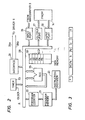
- Referring now to Fig. 1, there is shown a paging receiver embodying the present invention. The paging receiver comprises a
tuner 2 having one or more radio frequency amplifier stages, a local oscillator and a mixer for receiving a radio frequency signal intercepted by anantenna 1 and converts the radio frequency to an intermediate frequency. The output of thetuner 2 is applied to awaveshaper 3 wherein the signal is shaped into a waveform having sharply defined edges and distinguishable voltage levels suitable for it to be processed in a microprocessor-baseddecoder 4. Thetuner 2 andwaveshaper 3 receive power from abattery 11. Since the tuner and waveshaper are constructed of discrete components, these circuits account for a greater part of the total power consumption of the system. For power saving purposes anelectronic switching circuit 10 is provided in a power line to these components to periodically cut it off during idle periods in response to a signal from thedecoder 4. - A DC-
DC converter 12 steps up the battery voltage to a level sufficient to operate thedecoder 4. The microprocessor-baseddecoder 4 is in receipt of clock pulses from aclock source 13 to perform decoding operations on the signal recevied from thewaveshaper 3 in synchronized fashion with associated external circuits which include adrive circuit 6, an 8-digit liquidcrystal display panel 5, and a programmable read only memory (PROM) 14. - In the
PROM 14 is stored a subscriber's own address codeword with which the received address codewords are each checked to detect a match therebetween. When this occurs, thedecoder 4 activates anaudio frequency oscillator 7 to apply a tone signal to aloudspeaker 8 to alert the user that he is being paged. Amanual key 15 is provided to terminate the alarm sound. In one embodiment, the user is further urged to operate thekey 15 each time a predetermined amount of characters is displayed on thepanel 5. - As illustrated in Fig. 2, the
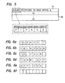
decoder 4 comprises aninstruction decoder 20 which translates the instructions it receives from aprogram memory 21 when addressed by aprogram counter 22. A multi-timer 23 which provides timing signals to various parts of the system. Anarithmetic logic unit 25 executes arithmetic and logic operations in accordance with instructions issued from thedecoder 20. The signal from thewaveshaper 3 is applied to aninput port 26. - The code format of the paging system, shown in Fig. 3, starts with a preable P followed by a word synchronization codeword SC to attain word synchronization for a sequence of subscriber data including address codewords A and message codewords I. The end of the format is indicated by an end-of-transmission codeword E.
- During idle periods the power saving operation is effected to open the
electronic switch 10 at intervals to to reduce the amount of power dissipated in the tuner and waveshaper. When the input signal is received from thewaveshaper 3 throughinput port 26 and a preamble P is detected, the power saving operation is discontinued by the decoder. Themicroprocessor 20 proceeds to detect a word synchronization codeword SC to establish word synchronization and then to compare the succeeding address codeword A1 against the address data stored in thePROM 14 by successively addressing it through anoutput port 27 and reading the addressed data through aninput port 28. - If the address codeword A is matched with the user's own address codeword, the
tone oscillator 7 is energized to generate a sound alarm. A succeeding message codeword I1 is then loaded into a storage location d1 of adata memory 30. Upon the operation ofkey 15, the message codeword I1 is read out of thememory 30 in a manner as will be detailed hereinbelow and transmitted from aninterface 24 on aline 24a to thedriver 6 and thence to thedisplay panel 5 with an associated synchronization code on aline 24b. In response to the receipt of an end-of-transmissi.on codeword E, themicroprocessor 20 places an enabling signal to theelectronic switch 10 to reinitiate the power saving operation. - Fig. 4 is a flowchart describing a display operation according to a first preferred embodiment of the present invention. In this embodiment, the
display panel 5 comprises an eight-segment liquid crystal display. Under certain circumstances where a lengthy word contains more than eight characters, only the eight most significant digit characters are displayed. However, the loss of one or two least significant digit codes does not materially affect on the.intelligibility of the word. - After detecting the address codeword A1, the microprocessor starts executing the programmed instructions at
Step 31 by loading the succeeding message codeword I1, which typically comprises a sequence of 7-bit ASCII codes, for example "PLEASE TELEPHONE TO YOUR OFFICE *", into the location d1 ofmemory 30 as illustrated in Fig. 5. Themicroprocessor 20 goes to aStep 32 to check if themanual key 15 has been operated, and if so, executes aStep 33 by reading eight 7-bit codes "PLEASE T" from the MSD to MSD-7 digit positions of memory location d1 and executes aStep 34 by putting the data on display as shown in Fig. 6a. TheStep 32 will be repeatedly executed until the key 15 is operated. - At
Step 35, the microprocessor checks if there is a blank in the MSD position of memory location dl. and if not, executes aStep 36 to decrement a "variable" stored in an MSD position by one and returns through aStep 38 to theStep 35. TheSteps Step 37 to decrement the MSD variable by one so that the current status of the MSD variable is MSD-7, or the eighth MSD position where the character "T" is stored. The microprocessor now returns to theStep 32 to check if the key 15 is again operated, and if so, theStep 33 is executed to read the next eight 7-bit codes from the MSD-7 to MSD-14 positions using the current MSD variable, so that the codes "TELEPHON" are retrieved, and subsequently displayed in Step 34 (see Fig. 6b). - The above process is repeated to provide display as shown in Figs. 6c to 6e until an asterisk "*" which is located at the end of the message is detected in
Step 38. TheStep 38 is followed by aStep 39 to detect if the key 15 is operated, and if so, thedisplay panel 5 is cleared (Fig. 6f) inStep 40 to permit the microprocessor to return to theStep 32 to repeat the above process. If theswitch 15 is not detected as being operated inStep 39, a delay time of 8 second is set in a memory inStep 41 and counted inStep 42. After the 8-second pause lapses, the program returns to Step 39, so that the status of theswitch 15 is checked at 8-second intervals until it is operated. It is seen therefore that according to the first embodiment of the invention, the message is scrolled manually on a per word group basis. - According to a second embodiment of the invention, the message is scrolled automatically on a per wordgroup basis. Fig. 7 is an illustration of a flowchart according to this embodiment. Similar to the
Step 31 of Fig. 4, a message codeword is loaded into memory location d inStep 41, and followed by aStep 42 to check if the key 15 is operated, and if so, Steps 43 and 44 are successively executed to display the first eight characters "PLEASE T". AtStep 45, a "1-second" delay.time flag is set up in a memory location d2. Clock is counted inStep 46 to check if 1 second has lapsed. AStep 47 is executed to check if a blank is present in the MSD position of the memory location dl. AStep 48 is then executed if no blank is detected inStep 47 to decrement the MSD variable by one. The microprocessor goes to aStep 50 to detect the asterisk and if not, returns to theStep 47 to successively decrement the MSD variable until the blank in the MSD-6 position is detected atStep 47. If a blank is detected inStep 47 the microprocessor exits to aStep 49 to further decrement the MSD variable by one so that the current status of the MSD variable is MSD-7. The microprocessor returns to theStep 43 to reset thedisplay panel 5 and read out the next eight characters "TELEPHON". When the asterisk is detected inStep 50, an 8-second delay is introduced bySteps display panel 5 atStep 53. After execution ofStep 53, the program returns to Step 42. Therefore, the message is scrolled automatically at 1-second intervals on a per wordgroup basis. - The flowchart of Fig. 7 is modified as shown in Fig. 8 which differs from the Fig. 7 embodiment by the inclusion of a string of
Steps 52 to 55 interposed between theSteps Step 48 so that its current value is MSD-1, the eight characters of the MSD-1 to MSD-8 ("ELEPHONE") are read out of memory location d1 atStep 52 and displayed atStep 53. A 0.3-second delay time flag is set up in a memory location d3 atStep 54 and this time interval is checked atStep 55. After the introduction of a 0.3-second interval, the microprocessor returns throughStep 50 to theStep 47 to repeat the string ofSteps Step 47. - It is seen therefore that the first eight characters "PLEASE T" remain displayed for a 1-second period and are then scrolled at 0.3 intervals so that one character disappears from the display and another appears until the blank between E and T moves to the leftmost segment of the display panel and subsequently the next eight characters "TELEPHON" remains displayed for a I-second period. In this embodiment, all the characters of a word having more than 8 characters are made to appear on the display panel during the 0.3-second interval scroll.
- Figs. 9a and 9b are a flowchart of a further preferred embodiment of the present invention. In the previous embodiments the last word of any sequence is partially displayed if this word spills over the end of the display panel.
- In the present embodiment, the previously used MSD variable is divided into a first variable WN which represents the number of characters counted before a blank is detected, a second variable DS which is updated with and accumulate the first variable, and a third variable or display pointer DP which is updated each time a sequence of characters is displayed to accumulate the second variable.. These variables are stored in WN, DS and DP registers, respectively. The total count of the DP and DS registers are used to determine the characters to be displayed when the total count of the WN and DS registers exceeds the maximum number of display elements.
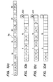
- For purposes of illustration a 16-element display panel is used and a sentence "PLEASE GO TO 19TH HOLE AT 3 PM*" is stored in a memory location d5. As illustrated in Fig. 10a, the characters stored in location d5 are each identified by an address code corresponding to the total value of DP, DS and WN registers, which is expressed in the flowchart as a function f(DP + DS + WN). On the other hand, the characters to be displayed are addressed by a code corresponding to the total count of the DP and DS registers which is expressed in the flowchart as a function f(DP + DS).
- Referring to Figs. 9a and 9b, the program starts when the input data are stored in memory location d5 and the key 15 operated. At
Step 61 the display pointer register DP is set to "1", atStep 62 the DS register is set to "0", and atStep 63 the WN register and a flag are both set to "0". AtStep 64, the microprocessor checks if the digit position identified by the total count of the DP, DS and WN registers is a blank, and if not, goes to aStep 65 to check if that digit position is an asterisk, and if not, goes to aStep 66 to set up the flag and thence to aStep 67 to increment the WN register by one and returns to theStep 64. The microprocessor passes throughSteps Step 64 repeatedly to scan the characters "PLEASE" to detect a blank that follows whenDP 1, DS = 0, WN = 6, and passes through aStep 68 to aStep 69. The total of DS and WN registers, which indicates the number of digit positions scanned up to this moment, is checked if it is still smaller than the maximum number of the available display segments to allow the microprocessor to increment the DS register by an amount equal to the first variable WN inStep 70 and return to Step 63 to reset the WN register and flag to "0". With the blank at the 7th digit position being detected and the flag being reset to zero, the microprocessor now passes throughSteps Step 67 to shift the scanning point to the 8th digit position to detect the character "G". Thus, Steps 64, 65, 66, 67 and back to 64 are repeatedly looped to scan the next word "GO".Step 68 is then executed when the scanning point reaches the tenth digit position where a second blank is stored to permit the microprocessor to check if the number of scanned characters is still smaller than 16. Therefore, the first variable WN is reset each time a blank is detected, while the second variable DS is incremented by an amount equal to the first variable before the first variable is reset to zero. - The above process is repeated until the scanning point reaches the 17th digit position. The total count of DS and WN registers is now 17 and the microprocessor exits from
Step 69 to a .Step 71 to put an arrow head on aseparate display element 100 located above the 16-th digit position of the display panel 5 (see Fig. 10b). This arrow head indicates that there is still at least one word to follow. At this moment, the total count of the DP and DS registers equals 13 (= 1 + 12). - The microprocessor advances to a
Step 72 to address the characters as a function of variables from DP=1 to DP= 1 + 12 to display the characters "PLEASE GO TO" (Fig. 10b) in a first display cycle. - .These characters remain on display for a period of 1 second by setting 1-second pause data into a memory location d5 in
Step 73 and checking the elapse of this period inStep 74. TheSteps - At the end of a display cycle, the display pointer DP is incremented by an amount equal to the second variable DS in
Step 75. AtStep 76, a digit position addressible by the updated display pointer DP is checked if it is filled with an asterisk, and if not, Steps 77 and 78 are repeatedly executed to increment the variable DP by one until the first character of the next word "19TH" is detected inStep 77. The microprocessor now returns to theStep 62 to reinitiate the second display cycle by repeating the above process to display "'19TH HOLE AT 3". - During the second display cycle the display pointer DP remains set to 14. The first, WN variable is incremented to 4 by the characters "19TH", reset to zero, and then incremented to 5 by the characters "HOLE" plus a blank that follows, then reset to zero and incremented to 3 by the characters "AT" pluse a following blank, reset to zero by that blank and incremented to 2 by the character "3" plus a following blank, reset again by the last-mentioned blank and incremented to 3 by the characters "PM*". Therefore, the DS variable is incremented to 14 by the time all the digit positions are scanned. An asterisk is now detected in
Step 65 and the microprocessor goes to aStep 79 to increment the WN variable by one and goes to aStep 80 to check if the total of DS and WN variables exceeds 16 to allow the microprocessor to exit to theStep 71 to put an arrow head on display at the 16th digit position (Fig. lOc). Since the DP and DS variables are both 14, the characters stored in the 14th to 28th digit positions are addressed inStep 72 for display as a function of variables from DP=14 to DP=14 + 14. Upon the elapse of a 1-second interval, the DP variable is again incremented by an amount equal to DS which is now 14, so that DP is now 28. InStep 76, the digit position corresponding to DP=28 is checked if it contains an asterisk and control exits to Step 77 to increment WN by one inStep 78 to return toStep 63. - During the third display cycle, the DP variable is incremented to 29 by execution of
Steps Step 65 to follow theSteps head display step 71 is bypassed to allow only the last word "PM*" to be displayed inStep 72. After a 1-second interval, the DP variable is set to 31 (= 29 + 2) corresponding to the digit position of the asterik which is detected inStep 76 to terminate the program. - The foregoing description shows only preferred embodiments of the present invention. Various modifications are apparent to those skilled in the art without departing from the scope of the present invention which is only limited by the appended claims. Therefore, the embodiments shown and described are only illustrative, not restrictive.
Claims (17)
Applications Claiming Priority (2)
| Application Number | Priority Date | Filing Date | Title |
|---|---|---|---|
| JP62022/82 | 1982-04-13 | ||
| JP57062022A JPS58178642A (en) | 1982-04-13 | 1982-04-13 | Individual selection and calling receiver with display |
Publications (3)
| Publication Number | Publication Date |
|---|---|
| EP0091691A2 true EP0091691A2 (en) | 1983-10-19 |
| EP0091691A3 EP0091691A3 (en) | 1987-03-25 |
| EP0091691B1 EP0091691B1 (en) | 1991-07-10 |
Family
ID=13188125
Family Applications (1)
| Application Number | Title | Priority Date | Filing Date |
|---|---|---|---|
| EP83103537A Expired EP0091691B1 (en) | 1982-04-13 | 1983-04-12 | Radio paging receiver operable on a word-scrolling basis |
Country Status (9)
| Country | Link |
|---|---|
| US (2) | US4646081A (en) |
| EP (1) | EP0091691B1 (en) |
| JP (1) | JPS58178642A (en) |
| KR (1) | KR860001459B1 (en) |
| AU (1) | AU573171B2 (en) |
| CA (1) | CA1219917A (en) |
| DE (1) | DE3382331D1 (en) |
| HK (1) | HK30193A (en) |
| SG (1) | SG128092G (en) |
Cited By (5)
| Publication number | Priority date | Publication date | Assignee | Title |
|---|---|---|---|---|
| EP0218936A2 (en) * | 1985-09-17 | 1987-04-22 | Nec Corporation | Selective paging receiver with message display |
| EP0275165A2 (en) * | 1987-01-13 | 1988-07-20 | Nec Corporation | Selective calling radio display pager |
| GB2207265A (en) * | 1987-07-07 | 1989-01-25 | Chinese Computers Ltd | Chinese character displays |
| EP0606231A1 (en) * | 1991-09-30 | 1994-07-20 | Motorola, Inc. | Combination liquid crystal display driver and varactor voltage power supply |
| FR2708371A1 (en) * | 1993-07-01 | 1995-02-03 | Motorola Inc | High persistence display circuit and associated method. |
Families Citing this family (50)
| Publication number | Priority date | Publication date | Assignee | Title |
|---|---|---|---|---|
| US4754423A (en) * | 1986-06-16 | 1988-06-28 | Motorola, Inc. | Electronic selector and method for selecting desired functions and levels |
| EP0249961B1 (en) * | 1986-06-17 | 1994-09-14 | Sharp Kabushiki Kaisha | Data processing device for use in statistic calculation |
| EP0253138B1 (en) * | 1986-06-17 | 1992-02-05 | Sharp Kabushiki Kaisha | Data processing device |
| CA1317350C (en) * | 1987-08-05 | 1993-05-04 | Michael Joseph De Luca | Paging receiver with dynamically allocated display rate |
| US4952927A (en) * | 1987-08-05 | 1990-08-28 | Motorola, Inc. | Paging receiver with dynamically allocated display rate |
| AU617125B2 (en) * | 1987-08-05 | 1991-11-21 | Motorola, Inc. | Paging receiver with dynamically allocated display rate |
| KR910003233B1 (en) * | 1988-03-29 | 1991-05-24 | 삼성전자 주식회사 | Method for display data in paging receiver |
| FR2632467B1 (en) * | 1988-06-03 | 1994-05-20 | Thomson Csf | THEATER BOOKLET AND WRITING INSTRUCTIONS FOR THIS BOOKLET |
| US5124942A (en) * | 1988-09-28 | 1992-06-23 | Solatrol, Inc. | Machine interface with cyclically displayed hierarchical menus and user selection of menu items by actuation of a single switch |
| US5187797A (en) * | 1988-09-28 | 1993-02-16 | Solatrol, Inc. | Machine interface system with hierarchal menus allowing user sequencing and selection of menu items by actuation of three switches |
| KR930002752B1 (en) * | 1988-09-29 | 1993-04-09 | 삼성전자 주식회사 | Method for display messages of paging receiver |
| US5285493A (en) * | 1989-01-19 | 1994-02-08 | Kabushiki Kaisha Toshiba | Radio tele-communication device with received message displaying feature |
| US5146612A (en) * | 1989-04-17 | 1992-09-08 | Spingarn James L | Technique for using a subcarrier frequency of a radio station to transmit, receive and display a message together with audio reproduction of the radio program |
| AU5544690A (en) * | 1989-04-17 | 1990-11-16 | Spingarn, James L. | Technique for using a subcarrier frequency of a radio station to transmit, receive and display a message together with audio reproduction of the radio program |
| US5146216A (en) * | 1989-12-14 | 1992-09-08 | Motorola, Inc. | Multiple message signalling protocol for a selective call receiver |
| JP2770838B2 (en) * | 1992-01-20 | 1998-07-02 | 日本電気株式会社 | Radio selective call receiver |
| EP0561435B1 (en) * | 1992-02-19 | 1999-05-12 | Koninklijke Philips Electronics N.V. | Information transfer system, a transmitter, a receiver and a record carrier for use in the system |
| GB2270582B (en) * | 1992-09-10 | 1996-01-17 | Nokia Mobile Phones Uk | A display |
| US5583921A (en) * | 1992-09-21 | 1996-12-10 | Casio Computer Co., Ltd. | Data transmitting/receiving apparatus and data communication system |
| US5495234A (en) * | 1993-01-21 | 1996-02-27 | Motorola, Inc. | Method and apparatus for length dependent selective call message handling |
| US5481255A (en) * | 1993-02-10 | 1996-01-02 | Data Critical Corp. | Paging transmission system |
| US5602563A (en) * | 1993-12-15 | 1997-02-11 | International Business Machines Corporation | Float to surface display |
| JPH07240953A (en) * | 1994-02-25 | 1995-09-12 | Matsushita Electric Ind Co Ltd | Selective call receiver |
| US5640153A (en) * | 1994-12-02 | 1997-06-17 | Excel Energy Technologies, Ltd. | Energy utilization controller and control system and method |
| JP3433543B2 (en) * | 1994-12-27 | 2003-08-04 | カシオ計算機株式会社 | Communication system, communication device, and communication method |
| KR960024839A (en) * | 1994-12-29 | 1996-07-20 | 김광호 | Portable information terminal and information input method using soft keyboard |
| US5703609A (en) * | 1995-03-10 | 1997-12-30 | Eastman Kodak Company | Emulation of single line display with multi-line display driver |
| US6292176B1 (en) * | 1996-02-26 | 2001-09-18 | Motorola, Inc. | Method and system for displaying textual information |
| JP2834091B2 (en) * | 1996-08-15 | 1998-12-09 | 静岡日本電気株式会社 | Radio selective call receiver |
| US6201526B1 (en) | 1996-09-04 | 2001-03-13 | Motorola, Inc. | Visual display device |
| US5867140A (en) * | 1996-11-27 | 1999-02-02 | Motorola, Inc. | Display system and circuit therefor |
| JPH10207445A (en) * | 1997-01-28 | 1998-08-07 | Seiko Epson Corp | Information display equipment |
| US20010038391A1 (en) * | 1997-01-28 | 2001-11-08 | Hideo Fukuchi | Information display apparatus |
| US6545588B1 (en) | 1997-02-28 | 2003-04-08 | Sony Corporation | Pager with rotating knob and character display for inputting messages |
| US5914669A (en) * | 1997-03-06 | 1999-06-22 | Sony Corporation | Pager with rotating dial for inputting messages |
| US6098085A (en) * | 1997-03-17 | 2000-08-01 | At&T Corp. | Word-serial reader for network devices having limited display capabilities |
| JP3565682B2 (en) * | 1997-06-02 | 2004-09-15 | シャープ株式会社 | Information terminal device having transmission information display function |
| US6084969A (en) * | 1997-12-31 | 2000-07-04 | V-One Corporation | Key encryption system and method, pager unit, and pager proxy for a two-way alphanumeric pager network |
| US20010013871A1 (en) * | 1998-04-24 | 2001-08-16 | Dennis L. Kucmerowski | Intelligent default |
| JP3097077B2 (en) * | 1998-05-11 | 2000-10-10 | 日本電気株式会社 | Selective call receiver and receiver |
| JP3374771B2 (en) * | 1998-12-16 | 2003-02-10 | 株式会社デンソー | Communication terminal device |
| EP1081583A3 (en) * | 1999-08-31 | 2005-07-06 | Sony Corporation | Menu display system |
| US6264614B1 (en) | 1999-08-31 | 2001-07-24 | Data Critical Corporation | System and method for generating and transferring medical data |
| US6556131B1 (en) * | 2000-02-23 | 2003-04-29 | Motorola, Inc. | Method for indicating that only a portion of a received message can be displayed and communication device employing same |
| SE524403C2 (en) * | 2000-11-06 | 2004-08-03 | Ericsson Telefon Ab L M | System and method for customizable RSVP-based text display |
| KR100462899B1 (en) * | 2003-02-07 | 2004-12-18 | 삼성전자주식회사 | apparatus and method for display controlling a channel information of electronic program guide |
| JP2006030566A (en) * | 2004-07-15 | 2006-02-02 | Tohoku Pioneer Corp | Electronic apparatus equipped with display panel |
| JP2008096351A (en) * | 2006-10-13 | 2008-04-24 | Tlv Co Ltd | Vibrometer |
| JP2008096350A (en) * | 2006-10-13 | 2008-04-24 | Tlv Co Ltd | Vibrometer |
| IT201800021013A1 (en) * | 2018-12-24 | 2020-06-24 | Borgwarner System Lugo S R L | Battery charger with alphanumeric display |
Citations (1)
| Publication number | Priority date | Publication date | Assignee | Title |
|---|---|---|---|---|
| GB2062320A (en) * | 1979-11-01 | 1981-05-20 | Nippon Electric Co | Paging receiver with dispaly |
Family Cites Families (8)
| Publication number | Priority date | Publication date | Assignee | Title |
|---|---|---|---|---|
| US3938139A (en) * | 1974-12-30 | 1976-02-10 | Young Communications Corporation | Miniature display communicator |
| US3976995A (en) * | 1975-05-22 | 1976-08-24 | Sanders Associates, Inc. | Precessing display pager |
| US4373192A (en) * | 1979-08-27 | 1983-02-08 | Sharp Kabushiki Kaisha | Display device of an electronic language interpreter |
| US4392135A (en) * | 1979-09-29 | 1983-07-05 | Nippon Electric Co., Ltd. | Paging receivers |
| JPS5654133A (en) * | 1979-10-09 | 1981-05-14 | Nec Corp | Selective callout receiver |
| JPS5857773B2 (en) * | 1979-10-30 | 1983-12-21 | シャープ株式会社 | information display device |
| JPS5792932A (en) * | 1980-12-01 | 1982-06-09 | Nec Corp | Selective calling receiver with display |
| DE3209187C2 (en) * | 1982-03-13 | 1985-01-10 | Triumph-Adler Aktiengesellschaft für Büro- und Informationstechnik, 8500 Nürnberg | Method for displaying a text on a single-line display device of a text creation device |
-
1982
- 1982-04-13 JP JP57062022A patent/JPS58178642A/en active Granted
-
1983
- 1983-04-12 CA CA000425678A patent/CA1219917A/en not_active Expired
- 1983-04-12 DE DE8383103537T patent/DE3382331D1/en not_active Expired - Lifetime
- 1983-04-12 EP EP83103537A patent/EP0091691B1/en not_active Expired
- 1983-04-12 AU AU13429/83A patent/AU573171B2/en not_active Ceased
- 1983-04-13 KR KR1019830001536A patent/KR860001459B1/en not_active IP Right Cessation
-
1986
- 1986-03-10 US US06/838,205 patent/US4646081A/en not_active Expired - Lifetime
- 1986-08-14 US US06/896,369 patent/US4660032A/en not_active Expired - Lifetime
-
1992
- 1992-12-17 SG SG1280/92A patent/SG128092G/en unknown
-
1993
- 1993-03-25 HK HK301/93A patent/HK30193A/en not_active IP Right Cessation
Patent Citations (1)
| Publication number | Priority date | Publication date | Assignee | Title |
|---|---|---|---|---|
| GB2062320A (en) * | 1979-11-01 | 1981-05-20 | Nippon Electric Co | Paging receiver with dispaly |
Cited By (9)
| Publication number | Priority date | Publication date | Assignee | Title |
|---|---|---|---|---|
| EP0218936A2 (en) * | 1985-09-17 | 1987-04-22 | Nec Corporation | Selective paging receiver with message display |
| EP0218936A3 (en) * | 1985-09-17 | 1988-09-14 | Nec Corporation | Selective paging receiver with message display |
| EP0275165A2 (en) * | 1987-01-13 | 1988-07-20 | Nec Corporation | Selective calling radio display pager |
| EP0275165A3 (en) * | 1987-01-13 | 1990-07-04 | Nec Corporation | Selective calling radio display pager |
| GB2207265A (en) * | 1987-07-07 | 1989-01-25 | Chinese Computers Ltd | Chinese character displays |
| GB2207265B (en) * | 1987-07-07 | 1991-07-10 | Chinese Computers Ltd | Improvements in or relating to chinese character displays |
| EP0606231A1 (en) * | 1991-09-30 | 1994-07-20 | Motorola, Inc. | Combination liquid crystal display driver and varactor voltage power supply |
| EP0606231A4 (en) * | 1991-09-30 | 1994-11-17 | Motorola Inc | Combination liquid crystal display driver and varactor voltage power supply. |
| FR2708371A1 (en) * | 1993-07-01 | 1995-02-03 | Motorola Inc | High persistence display circuit and associated method. |
Also Published As
| Publication number | Publication date |
|---|---|
| JPS6360933B2 (en) | 1988-11-25 |
| DE3382331D1 (en) | 1991-08-14 |
| US4660032A (en) | 1987-04-21 |
| SG128092G (en) | 1993-03-12 |
| HK30193A (en) | 1993-04-02 |
| EP0091691B1 (en) | 1991-07-10 |
| KR840004836A (en) | 1984-10-24 |
| JPS58178642A (en) | 1983-10-19 |
| CA1219917A (en) | 1987-03-31 |
| EP0091691A3 (en) | 1987-03-25 |
| AU1342983A (en) | 1983-10-20 |
| AU573171B2 (en) | 1988-06-02 |
| US4646081A (en) | 1987-02-24 |
| KR860001459B1 (en) | 1986-09-25 |
Similar Documents
| Publication | Publication Date | Title |
|---|---|---|
| EP0091691B1 (en) | Radio paging receiver operable on a word-scrolling basis | |
| EP0327533B1 (en) | Radio communication receiver with apparatus for altering bit rate of the receiver | |
| US4392135A (en) | Paging receivers | |
| WO1990016052A1 (en) | Means and method of displaying a message in a plurality of scripts | |
| US4768031A (en) | Radio paging receiver having a message protection capability | |
| US5323148A (en) | Selective call receiver presenting the length of an alphanumeric message prior to presentation of the message | |
| EP0275165B1 (en) | Selective calling radio display pager | |
| US6373450B1 (en) | Method and device for controlling selection using a switch | |
| US6201526B1 (en) | Visual display device | |
| US5396229A (en) | Selective calling receiver | |
| KR970000564B1 (en) | Radio paging receiver | |
| US5774061A (en) | Radio selective calling receiver with message display capability | |
| CA2060628C (en) | Pager receiver with message display function | |
| US6021313A (en) | Radio selective call receiver with time lapsed image display | |
| US5304991A (en) | Selective call radio paging receiver having display function and reduced control inputs | |
| US5577045A (en) | Selective call receiver for recovering garbled message fragments | |
| KR910003233B1 (en) | Method for display data in paging receiver | |
| JPS58209238A (en) | Radio individual selecting and calling receiver provided with receiving function of message information | |
| US5734331A (en) | Input control for radio selective calling receiver | |
| KR950014887B1 (en) | The pager having multi function | |
| KR0164832B1 (en) | Paging message automatic scrolling method of wireless paging receiver | |
| KR100228912B1 (en) | Method for displaying continuous message in paging receiver | |
| KR0140415B1 (en) | Country code display method in international calls | |
| JPH04225629A (en) | Selective calling receiver | |
| EP0726684A2 (en) | Intermittent receiving control apparatus of a selective calling receiver |
Legal Events
| Date | Code | Title | Description |
|---|---|---|---|
| PUAI | Public reference made under article 153(3) epc to a published international application that has entered the european phase |
Free format text: ORIGINAL CODE: 0009012 |
|
| AK | Designated contracting states |
Designated state(s): DE FR GB NL SE |
|
| 17P | Request for examination filed |
Effective date: 19831209 |
|
| PUAL | Search report despatched |
Free format text: ORIGINAL CODE: 0009013 |
|
| AK | Designated contracting states |
Kind code of ref document: A3 Designated state(s): DE FR GB NL SE |
|
| 17Q | First examination report despatched |
Effective date: 19890717 |
|
| GRAA | (expected) grant |
Free format text: ORIGINAL CODE: 0009210 |
|
| AK | Designated contracting states |
Kind code of ref document: B1 Designated state(s): DE FR GB NL SE |
|
| ET | Fr: translation filed | ||
| REF | Corresponds to: |
Ref document number: 3382331 Country of ref document: DE Date of ref document: 19910814 |
|
| PLBE | No opposition filed within time limit |
Free format text: ORIGINAL CODE: 0009261 |
|
| STAA | Information on the status of an ep patent application or granted ep patent |
Free format text: STATUS: NO OPPOSITION FILED WITHIN TIME LIMIT |
|
| 26N | No opposition filed | ||
| EAL | Se: european patent in force in sweden |
Ref document number: 83103537.3 |
|
| PGFP | Annual fee paid to national office [announced via postgrant information from national office to epo] |
Ref country code: SE Payment date: 20000406 Year of fee payment: 18 |
|
| PGFP | Annual fee paid to national office [announced via postgrant information from national office to epo] |
Ref country code: NL Payment date: 20000428 Year of fee payment: 18 |
|
| PG25 | Lapsed in a contracting state [announced via postgrant information from national office to epo] |
Ref country code: SE Free format text: LAPSE BECAUSE OF NON-PAYMENT OF DUE FEES Effective date: 20010413 |
|
| PG25 | Lapsed in a contracting state [announced via postgrant information from national office to epo] |
Ref country code: NL Free format text: LAPSE BECAUSE OF NON-PAYMENT OF DUE FEES Effective date: 20011101 |
|
| EUG | Se: european patent has lapsed |
Ref document number: 83103537.3 |
|
| REG | Reference to a national code |
Ref country code: GB Ref legal event code: IF02 |
|
| NLV4 | Nl: lapsed or anulled due to non-payment of the annual fee |
Effective date: 20011101 |
|
| PGFP | Annual fee paid to national office [announced via postgrant information from national office to epo] |
Ref country code: GB Payment date: 20020410 Year of fee payment: 20 Ref country code: FR Payment date: 20020410 Year of fee payment: 20 |
|
| PGFP | Annual fee paid to national office [announced via postgrant information from national office to epo] |
Ref country code: DE Payment date: 20020417 Year of fee payment: 20 |
|
| PG25 | Lapsed in a contracting state [announced via postgrant information from national office to epo] |
Ref country code: GB Free format text: LAPSE BECAUSE OF EXPIRATION OF PROTECTION Effective date: 20030411 |
|
| REG | Reference to a national code |
Ref country code: GB Ref legal event code: PE20 |