EP0091646A1 - Laser decontamination method - Google Patents
Laser decontamination method Download PDFInfo
- Publication number
- EP0091646A1 EP0091646A1 EP83103326A EP83103326A EP0091646A1 EP 0091646 A1 EP0091646 A1 EP 0091646A1 EP 83103326 A EP83103326 A EP 83103326A EP 83103326 A EP83103326 A EP 83103326A EP 0091646 A1 EP0091646 A1 EP 0091646A1
- Authority
- EP
- European Patent Office
- Prior art keywords
- laser
- component
- approximately
- components
- joules
- Prior art date
- Legal status (The legal status is an assumption and is not a legal conclusion. Google has not performed a legal analysis and makes no representation as to the accuracy of the status listed.)
- Granted
Links
Images
Classifications
-
- F—MECHANICAL ENGINEERING; LIGHTING; HEATING; WEAPONS; BLASTING
- F22—STEAM GENERATION
- F22B—METHODS OF STEAM GENERATION; STEAM BOILERS
- F22B37/00—Component parts or details of steam boilers
- F22B37/002—Component parts or details of steam boilers specially adapted for nuclear steam generators, e.g. maintenance, repairing or inspecting equipment not otherwise provided for
- F22B37/003—Maintenance, repairing or inspecting equipment positioned in or via the headers
-
- G—PHYSICS
- G21—NUCLEAR PHYSICS; NUCLEAR ENGINEERING
- G21F—PROTECTION AGAINST X-RADIATION, GAMMA RADIATION, CORPUSCULAR RADIATION OR PARTICLE BOMBARDMENT; TREATING RADIOACTIVELY CONTAMINATED MATERIAL; DECONTAMINATION ARRANGEMENTS THEREFOR
- G21F9/00—Treating radioactively contaminated material; Decontamination arrangements therefor
-
- B—PERFORMING OPERATIONS; TRANSPORTING
- B08—CLEANING
- B08B—CLEANING IN GENERAL; PREVENTION OF FOULING IN GENERAL
- B08B7/00—Cleaning by methods not provided for in a single other subclass or a single group in this subclass
- B08B7/0035—Cleaning by methods not provided for in a single other subclass or a single group in this subclass by radiant energy, e.g. UV, laser, light beam or the like
- B08B7/0042—Cleaning by methods not provided for in a single other subclass or a single group in this subclass by radiant energy, e.g. UV, laser, light beam or the like by laser
-
- G—PHYSICS
- G21—NUCLEAR PHYSICS; NUCLEAR ENGINEERING
- G21F—PROTECTION AGAINST X-RADIATION, GAMMA RADIATION, CORPUSCULAR RADIATION OR PARTICLE BOMBARDMENT; TREATING RADIOACTIVELY CONTAMINATED MATERIAL; DECONTAMINATION ARRANGEMENTS THEREFOR
- G21F9/00—Treating radioactively contaminated material; Decontamination arrangements therefor
- G21F9/001—Decontamination of contaminated objects, apparatus, clothes, food; Preventing contamination thereof
- G21F9/005—Decontamination of the surface of objects by ablation
Definitions
- This invention relates to decontamination methods and more particularly to methods for decontaminating components of nuclear power plants with the aid of lasers.
- a solution of this problem may be to reduce the radiation field associated with the component to allow the working personnel a longer working time.
- One approach for reducing the radiation field associated with the nuclear component on which the repair operation is to be performed is to remove the deposited film of radioactive metal oxides from the exposed surfaces of the nuclear component.
- the present invention resides in a. method for decontaminating radioactive nuclear components by removing a thin oxide layer of radioactively contaminated metal from the surface of said components thus lowering the radiation level associated with said components characterized in that the surface of said components is scanned by a laser beam of an energy density sufficient to achieve a thermal penetration corresponding to the thickness of said oxide layer and of a width substantially larger than the thickness of said oxide layer.
- a one-dimensional surface heating model of a laser beam interacting with a surface is generally known in the art. This model assumes that the laser beam is uniform with no transverse variations and that the surface film is approximately uniform. The model also assumes that the surface is planer and normal to the incident laser beam. These conditions are approximately true if:
- the first condition is satisfied in most situations where the laser beams are 0.1 to 1 cm in diameter and the oxide films of interest are typically less than 10-4 cm (approximately 40 microinches). In the case of typical nuclear components, the transverse dimensions of the actual laser beam are much greater than the oxide film thicknesses of the nuclear reactor component which satisfied the first condition.
- the second condition requires consideration of the thermal diffusivity for the material and the laser pulse length. For typical metals and metal oxides of nuclear reactor components, the thermal dif- f usivity is approximately 0.2 cm sq. per second.
- the distance that a thermal wave will advance into such a material during a typical laser pulse length of approximately 1 microsecond is approximately 4.0 x 10⁻⁴ cm which easily satisfies the second condition that the transverse dimensions of the actual laser beam be much greater than the thermal diffusion distance into the material.
- the third condition should be satisfied over most of the area of the nuclear component, because the lateral scale size for changes in the surface contour and oxide thickness is much greater than the average oxide thickness itself. Therefore, it appears that a one-dimensional surface heating model of a laser beam interacting with an oxide covered surface will adequately predict the interaction of a suitable laser on the oxide layer of a nuclear component.
- the oxide films encountered on nuclear components are typically less than approximately 10-4 cm. thick. It has been found that to achieve thermal penetration depths comparable to the film thicknesses on these components thereby avoiding extensive thermal damage to the base metal, the laser pulse length should be approximately one microsecond in duration. Both the pulsed TE C0 2 laser and Q-switched YAG laser can be used to satisfy this pulse length criteria.
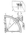
- a typical nuclear component that may be suitable for radioactive decontamination may be a nuclear steam generator and is referred to generally as 20.
- Steam generator 20 comprises an outer shell 22 with a divider plate 24 and tubesheet 26 disposed therein as is well known in the art.
- Outer shell 22, divider plate 24, and tubesheet 26 define a plenum 28 through which the reactor coolant passes.
- a manway 30 is provided in outer shell 22 for allowing access to plenum 28 by working personnel.
- a reactor coolant flows through plenum 28 and through tubes 32 which are disposed through tube sheet 26. Since the reactor coolant flowing through steam generator 20 is radioactive, various surfaces of steam generator 20 become deposited with an oxide film that is radioactive.
- the inner surface of shell 22, divider plate 24 and the lower surface of tube sheet 26 develop an oxide coating thereon that is radioactive.
- working personnel may enter plenum 28 through manway 30 to perform maintenance on tubes 32.
- the invention described herein provides a laser decontamination means for removing the oxide film on the surfaces of steam generator 20 to thereby reduce the radiation field associated with those surfaces.
- an optical mechanism 34 may be placed in plenum 28 and suspended from tubesheet 26 by attachment to the open ends of tubes 32.
- Optical mechanism 34 may comprise an electrically controlled movable reflective mechanism 36 for reflecting radiation, such as light, to various surfaces of the steam generator.
- reflective mechanism 36 may comprise a plurality of mirrors or prisms attached to the bottom of optical mechanism 34 for reflecting radiation that is directed to those reflective surfaces.
- Optical mechanism 34 is connected electrically by electrical line 38 to an optical mechanism power supply 40 which may be located remote from steam generator 20 and separated from steam generator 20 by a biological shield 42. In this manner, optical mechanism 34 may be remotely controlled and manipulated so that the operator is not exposed to the radiation field associated with steam generator 20.
- Optical mechanism power supply 40 provides a means by which optical mechanism 34 may be adjusted so as to change the reflective angles of the mirrors or prisms of reflective mechanism 36 which thereby redirects the radiation that is reflected from the mirrors or prisms to the desired surface to be decontaminated.
- a power laser 46 as previously described herein may be arranged near the opening of manway 30 so that the radiation emitted from power laser 46 may be directed toward optical mechanism 34 as shown in the drawing.
- Power laser 46 may be mounted on a support fixture 48 that is capable of moving power laser 46 relative to manway 30 and relative to optical mechanism 34 for properly aligning the radiation beam emitted from power laser 46.
- Support fixture 48 may be mounted on a generator platform 50 arranged near the opening of manway 30.
- Power laser 46 is connected electrically by electrical line 52 to laser power supply 54 located remote from steam generator 20 and behind a biological shield 42.
- Power laser 46 may be a laser capable of emitting pulses of radiation with pulse lengths of less than 100 microseconds and preferably less than approximately 1 microseconds in duration. Power laser 46 may also be capable of emitting pulses having a wavelength of less than approximately 12 micrometers and preferably between approximately 0.30 to 1.5 micrometers for typical decontamination applications. In addition, power laser 46 may be capable of producing pulses with energy densities of between 0.5 to 1.5 x 10 3 joules/cm 2 and preferably of approximately 4.5-23 joules/cm 2 at the surface to be decontaminated. Of course, typical optical instruments such as lenses and mirrors may be employed in conjunction with power laser 46 to achieve the desired energy densities at the surface.
- power laser 46 may be a Neodymium YAG pulsed laser capable of emitting pulses of radiation with a wavelength of approximately 1.06 micrometers, an energy output of approximately 0.3 joules/pulse, a pulse length of approximately 30-40 nanoseconds and an energy density of approximately 8-9 joules/ 2 cm .
- a shield plate 56 having an aperture 58 may be bolted to the outside of manway 30 for isolating plenum 28 from the outside of steam generator 20 for containing the radiation removed from the surfaces of plenum 28.
- Aperture 58 is provided for allowing the radiation beam from power laser 46 to pass therethrough and at optical mechanism 34.
- a suction mechanism 60 may also be attached to shield plate 56 and extend therethrough into plenum 28 and may extend at the other end to a radioactive waste filtering system 62.
- Suction mechanism 60 provides a means by which the contamination removed from plenum 28 may be suctioned out of plenum 28 and into a radioactive waste filtering system 62 for disposal of the waste.
- steam generator 20 is deactivated and the reactor coolant is drained therefrom.
- the manway cover is removed from manway 30 and optical mechanism 34 is suspended from tube sheet 26 either manually or remotely.
- Shield plate 56 is then attached to manway 30 and power laser 46 is arranged near aperture 58 as shown in the drawing.
- power laser 46 is activated by laser power supply 54 so that a beam of radiation is emitted from power laser 46 and directed toward the reflective surfaces of optical mechanism 34. From the reflective mechanism 36 of optical mechanism 34, the radiation emitted from power laser 46 is reflected toward the selected surface of the interior of steam generator 20.
- Power laser 46 may be pulsed with a pulse length of approximately 3C-40 nanoseconds and at an energy level of approximately 0.3 joules/pulse so as to impinge the surface to be decontaminated with an energy density of approximately 50- 6 0 joules/in 2 .
- the laser radiation is such that it removes an oxide layer of approximately 0.0005 mm. from the surfaces of plenum 28 and thereby reduces the radiation field associated with the oxide film without damaging the base metal.
- the oxide layer removed is exhausted from plenum 28 by means of suction mechanism 60.
- optical mechanism 34 is controlled so as to allow the laser beam from power laser 46 to scan all of the surfaces of the interior of plenum 28. In this manner, the entire interior of plenum 28 may be decontaminated.
- power laser 46 need not be directed toward optical mechanism 34, but rather it can be aimed directly at the surface to be decontaminated.
- the invention provides a decontamination method that reduces the radiation field in components of nuclear reactor power plants without damaging the component.
Abstract
Description
- This invention relates to decontamination methods and more particularly to methods for decontaminating components of nuclear power plants with the aid of lasers.
- During the operation of nuclear power plants and similar apparatus, certain components become exposed to radiation and may develop a thin radioactive film on the surface of the component. From time to time, it is necessary to either inspect or repair these components of the nuclear reactor power plant. During the inspection or repair of the components, it is necessary for working personnel to enter the component or to be stationed in close proximity to the component whereby the working personnel may be exposed to radiation emitted from the contaminated component. In some circumstances, the radiation emitted from these components is such that a worker would receive the maximum permissible radiation dose in less than five minutes of working time. Such a situation means that a given worker may spend only a relatively short amount of time working on the inspection or the repair operation of the nuclear component. Having each worker spend a relatively short amount of time in the repair or inspection procedure, necessitates the use of many workers with each worker working a short time, in order to accomplish the desired result. While this may be an acceptable practice for minor inspections or repair procedures, this is not an acceptable practice where there is an extensive inspection or an extensive repair job to be performed. Where the procedure to be performed is a time-consuming procedure, it is likely that an unusally large number of highly trained personnel would be necessary to carry out the task. Such a situation may not only be unacceptable from a financial aspect, but may also be unacceptable from a manpower level aspect. A solution of this problem may be to reduce the radiation field associated with the component to allow the working personnel a longer working time. One approach for reducing the radiation field associated with the nuclear component on which the repair operation is to be performed, is to remove the deposited film of radioactive metal oxides from the exposed surfaces of the nuclear component.
- There are several methods known in the art for removing the radioactive oxide layer from the nuclear component so as to reduce the radiation field associated with that component. For example, an abrasive grit may be sprayed against the ' component to abrade the oxide film from the component thereby lowering the radiation field associated with the component. In addition, chemical processes have been attempted to dissolve the oxide film from the component to thereby remove the oxide film and associated radiation field from the component.
- In addition to the methods that have been previously attempted for reducing radiation fields associated with nuclear components, it is known in the prior art to use laser radiation and radiation from pulsed flash lamps to remove various kinds of surface films from objects such as artworks and structures. This type of laser radiation may employ intensities which have the ability to kill mildew on rare old books, to remove paint from metal surfaces, to chip away limestone deposits from Indian cliff paintings or to convert rust to magnetite on steel structures. However, none of these procedures have been developed for use in removing radioactive oxide films from nuclear components in a manner to prevent damage to the nuclear component and in a manner to prevent redeposition of higher levels of radioactive oxides on the nuclear component.
- It is therefore the principal object of the present invention to provide a decontamination method that reduces the radiation field adjacent to components of nuclear reactor power plants without damaging the component or creating a situation in which the rate of deposition of radioactive oxide on the component is accelerated when the component is returned to service.
- With this object in view, the present invention resides in a. method for decontaminating radioactive nuclear components by removing a thin oxide layer of radioactively contaminated metal from the surface of said components thus lowering the radiation level associated with said components characterized in that the surface of said components is scanned by a laser beam of an energy density sufficient to achieve a thermal penetration corresponding to the thickness of said oxide layer and of a width substantially larger than the thickness of said oxide layer.
- The invention will become more readily apparent from the following description of a preferred embodiment thereof shown, by way of example only, in the accompanied drawing, wherein the single figure is a schematic diagram of the laser apparatus to be employed. The invention, described herein, is a method for laser decontaminating nuclear components so that working personnel may perform operations thereon.
- A one-dimensional surface heating model of a laser beam interacting with a surface is generally known in the art. This model assumes that the laser beam is uniform with no transverse variations and that the surface film is approximately uniform. The model also assumes that the surface is planer and normal to the incident laser beam. These conditions are approximately true if:
- 1. The transverse dimensions of the actual laser beam are much greater than the surface film thickness;
- 2. The transverse dimensions of the actual laser beam are much greater than the thermal diffusion distance in the material; and
- 3. The lateral scale size for changes in the surface contour and film thickness is much greater than the average film thickness.
- The first condition is satisfied in most situations where the laser beams are 0.1 to 1 cm in diameter and the oxide films of interest are typically less than 10-4 cm (approximately 40 microinches). In the case of typical nuclear components, the transverse dimensions of the actual laser beam are much greater than the oxide film thicknesses of the nuclear reactor component which satisfied the first condition. The second condition requires consideration of the thermal diffusivity for the material and the laser pulse length. For typical metals and metal oxides of nuclear reactor components, the thermal dif- fusivity is approximately 0.2 cm sq. per second. The distance that a thermal wave will advance into such a material during a typical laser pulse length of approximately 1 microsecond is approximately 4.0 x 10⁻⁴ cm which easily satisfies the second condition that the transverse dimensions of the actual laser beam be much greater than the thermal diffusion distance into the material. The third condition should be satisfied over most of the area of the nuclear component, because the lateral scale size for changes in the surface contour and oxide thickness is much greater than the average oxide thickness itself. Therefore, it appears that a one-dimensional surface heating model of a laser beam interacting with an oxide covered surface will adequately predict the interaction of a suitable laser on the oxide layer of a nuclear component.
- As noted earlier, the oxide films encountered on nuclear components are typically less than approximately 10-4 cm. thick. It has been found that to achieve thermal penetration depths comparable to the film thicknesses on these components thereby avoiding extensive thermal damage to the base metal, the laser pulse length should be approximately one microsecond in duration. Both the pulsed TE C02 laser and Q-switched YAG laser can be used to satisfy this pulse length criteria.
- In addition to determining the penetration depth of a pulse of the laser, it is also important to be able to determine the oxide surface temperatures as a function of the incident laser pulse length so as to be able to ascertain the laser energy densities required. In order to remove oxide films of this nature, high surface temperatures of approximately 2,000-3,000°K are generally required. Since short laser pulses of approximately 1 microsecond are required to limit the thermal penetration depth to avoid base metal damage and in order to achieve surface temperatures of approximately 2,000-3,000°K with a laser pulse length of approximately 1 microsecond, it is generally desirable to have laser energy densities of approximately 1.5 to 3 joules per square cm. Laser energy densities of approximately 1.5 to 3 joules per square cm. are easily produced by pulsed C02 and YAG lasers.
- From this analysis, it can be seen that lasers are available having the required characteristics to remove radioactive oxide films from nuclear components without damaging the base metal of the component.
- Referring to the drawing, a typical nuclear component that may be suitable for radioactive decontamination may be a nuclear steam generator and is referred to generally as 20.
Steam generator 20 comprises anouter shell 22 with adivider plate 24 andtubesheet 26 disposed therein as is well known in the art.Outer shell 22,divider plate 24, andtubesheet 26 define aplenum 28 through which the reactor coolant passes. In addition, amanway 30 is provided inouter shell 22 for allowing access toplenum 28 by working personnel. During operation ofsteam generator 20, a reactor coolant flows throughplenum 28 and throughtubes 32 which are disposed throughtube sheet 26. Since the reactor coolant flowing throughsteam generator 20 is radioactive, various surfaces ofsteam generator 20 become deposited with an oxide film that is radioactive. For example, the inner surface ofshell 22,divider plate 24 and the lower surface oftube sheet 26 develop an oxide coating thereon that is radioactive. When it is desired to perform maintenance onheat exchanger tubes 32, working personnel may enterplenum 28 throughmanway 30 to perform maintenance ontubes 32. In order to increase the time in which working personnel may remain inplenum 28 to perform the maintenance, it is desirable to reduce the radiation field inplenum 28. This may be accomplished by removing the oxide film that is deposited on the surfaces of the components ofsteam generator 22 such asdivider plate 24,tubesheet 26 and the inner surface ofshell 22 thereby reducing the radiation field emitted therefrom. The invention described herein provides a laser decontamination means for removing the oxide film on the surfaces ofsteam generator 20 to thereby reduce the radiation field associated with those surfaces. - Still referring to the figure, when
steam generator 20 has been deactivated anoptical mechanism 34 may be placed inplenum 28 and suspended fromtubesheet 26 by attachment to the open ends oftubes 32.Optical mechanism 34 may comprise an electrically controlled movablereflective mechanism 36 for reflecting radiation, such as light, to various surfaces of the steam generator. For example,reflective mechanism 36 may comprise a plurality of mirrors or prisms attached to the bottom ofoptical mechanism 34 for reflecting radiation that is directed to those reflective surfaces.Optical mechanism 34 is connected electrically byelectrical line 38 to an opticalmechanism power supply 40 which may be located remote fromsteam generator 20 and separated fromsteam generator 20 by abiological shield 42. In this manner,optical mechanism 34 may be remotely controlled and manipulated so that the operator is not exposed to the radiation field associated withsteam generator 20. Opticalmechanism power supply 40 provides a means by whichoptical mechanism 34 may be adjusted so as to change the reflective angles of the mirrors or prisms ofreflective mechanism 36 which thereby redirects the radiation that is reflected from the mirrors or prisms to the desired surface to be decontaminated. - A
power laser 46 as previously described herein may be arranged near the opening ofmanway 30 so that the radiation emitted frompower laser 46 may be directed towardoptical mechanism 34 as shown in the drawing.Power laser 46 may be mounted on asupport fixture 48 that is capable of movingpower laser 46 relative to manway 30 and relative tooptical mechanism 34 for properly aligning the radiation beam emitted frompower laser 46.Support fixture 48 may be mounted on a generator platform 50 arranged near the opening ofmanway 30.Power laser 46 is connected electrically by electrical line 52 tolaser power supply 54 located remote fromsteam generator 20 and behind abiological shield 42. -
Power laser 46 may be a laser capable of emitting pulses of radiation with pulse lengths of less than 100 microseconds and preferably less than approximately 1 microseconds in duration.Power laser 46 may also be capable of emitting pulses having a wavelength of less than approximately 12 micrometers and preferably between approximately 0.30 to 1.5 micrometers for typical decontamination applications. In addition,power laser 46 may be capable of producing pulses with energy densities of between 0.5 to 1.5 x 10³ joules/cm2 and preferably of approximately 4.5-23 joules/cm2 at the surface to be decontaminated. Of course, typical optical instruments such as lenses and mirrors may be employed in conjunction withpower laser 46 to achieve the desired energy densities at the surface. More specifically,power laser 46 may be a Neodymium YAG pulsed laser capable of emitting pulses of radiation with a wavelength of approximately 1.06 micrometers, an energy output of approximately 0.3 joules/pulse, a pulse length of approximately 30-40 nanoseconds and an energy density of approximately 8-9 joules/ 2 cm . - A
shield plate 56 having anaperture 58 may be bolted to the outside ofmanway 30 for isolatingplenum 28 from the outside ofsteam generator 20 for containing the radiation removed from the surfaces ofplenum 28.Aperture 58 is provided for allowing the radiation beam frompower laser 46 to pass therethrough and atoptical mechanism 34. Asuction mechanism 60 may also be attached to shieldplate 56 and extend therethrough intoplenum 28 and may extend at the other end to a radioactivewaste filtering system 62.Suction mechanism 60 provides a means by which the contamination removed fromplenum 28 may be suctioned out ofplenum 28 and into a radioactivewaste filtering system 62 for disposal of the waste. - In operation,
steam generator 20 is deactivated and the reactor coolant is drained therefrom. The manway cover is removed frommanway 30 andoptical mechanism 34 is suspended fromtube sheet 26 either manually or remotely.Shield plate 56 is then attached to manway 30 andpower laser 46 is arranged nearaperture 58 as shown in the drawing. Next,power laser 46 is activated bylaser power supply 54 so that a beam of radiation is emitted frompower laser 46 and directed toward the reflective surfaces ofoptical mechanism 34. From thereflective mechanism 36 ofoptical mechanism 34, the radiation emitted frompower laser 46 is reflected toward the selected surface of the interior ofsteam generator 20.Power laser 46 may be pulsed with a pulse length of approximately 3C-40 nanoseconds and at an energy level of approximately 0.3 joules/pulse so as to impinge the surface to be decontaminated with an energy density of approximately 50-60 joules/in2. As described previously, the laser radiation is such that it removes an oxide layer of approximately 0.0005 mm. from the surfaces ofplenum 28 and thereby reduces the radiation field associated with the oxide film without damaging the base metal. The oxide layer removed is exhausted fromplenum 28 by means ofsuction mechanism 60. As this process continues,optical mechanism 34 is controlled so as to allow the laser beam frompower laser 46 to scan all of the surfaces of the interior ofplenum 28. In this manner, the entire interior ofplenum 28 may be decontaminated. Of course,power laser 46 need not be directed towardoptical mechanism 34, but rather it can be aimed directly at the surface to be decontaminated. - Therefore, the invention provides a decontamination method that reduces the radiation field in components of nuclear reactor power plants without damaging the component.
Claims (8)
Applications Claiming Priority (2)
| Application Number | Priority Date | Filing Date | Title |
|---|---|---|---|
| US36807582A | 1982-04-14 | 1982-04-14 | |
| US368075 | 1982-04-14 |
Publications (2)
| Publication Number | Publication Date |
|---|---|
| EP0091646A1 true EP0091646A1 (en) | 1983-10-19 |
| EP0091646B1 EP0091646B1 (en) | 1986-12-30 |
Family
ID=23449771
Family Applications (1)
| Application Number | Title | Priority Date | Filing Date |
|---|---|---|---|
| EP83103326A Expired EP0091646B1 (en) | 1982-04-14 | 1983-04-06 | Laser decontamination method |
Country Status (7)
| Country | Link |
|---|---|
| EP (1) | EP0091646B1 (en) |
| JP (1) | JPS58187898A (en) |
| KR (1) | KR840004610A (en) |
| CA (1) | CA1198482A (en) |
| DE (1) | DE3368800D1 (en) |
| ES (1) | ES8703050A1 (en) |
| FR (1) | FR2525380A1 (en) |
Cited By (22)
| Publication number | Priority date | Publication date | Assignee | Title |
|---|---|---|---|---|
| GB2169496A (en) * | 1985-01-16 | 1986-07-16 | Stc Plc | Cleaning metal surfaces |
| EP0507641A1 (en) * | 1991-04-05 | 1992-10-07 | Framatome | Process and equipment for working with a laser in a contaminated area of a nuclear plant |
| EP0520847A1 (en) * | 1991-06-26 | 1992-12-30 | Framatome | Process for working with a laser in a contaminated zone of a nuclear power plant and device for carrying out the process |
| WO1993013531A1 (en) * | 1992-01-04 | 1993-07-08 | British Nuclear Fuels Plc | Method of treating a surface contaminated with radionuclides |
| FR2700882A1 (en) * | 1993-01-26 | 1994-07-29 | Commissariat Energie Atomique | Method and installation for decontaminating a radioactive surface by means of a coherent light beam |
| EP0653762A1 (en) * | 1993-11-05 | 1995-05-17 | British Nuclear Fuels PLC | A method of treating a surface |
| WO1995013618A1 (en) * | 1993-11-09 | 1995-05-18 | British Nuclear Fuels Plc | Laser decontamination method |
| WO1995027986A1 (en) * | 1994-04-09 | 1995-10-19 | British Nuclear Fuels Plc | Material removal by laser ablation |
| WO1995035575A1 (en) * | 1994-06-17 | 1995-12-28 | British Nuclear Fuels Plc | Removing contamination |
| US5531857A (en) * | 1988-07-08 | 1996-07-02 | Cauldron Limited Partnership | Removal of surface contaminants by irradiation from a high energy source |
| EP0724929A2 (en) * | 1995-01-31 | 1996-08-07 | Kabushiki Kaisha Toshiba | Underwater laser processing method and apparatus |
| US5643472A (en) * | 1988-07-08 | 1997-07-01 | Cauldron Limited Partnership | Selective removal of material by irradiation |
| US5780806A (en) * | 1995-07-25 | 1998-07-14 | Lockheed Idaho Technologies Company | Laser ablation system, and method of decontaminating surfaces |
| US5821175A (en) * | 1988-07-08 | 1998-10-13 | Cauldron Limited Partnership | Removal of surface contaminants by irradiation using various methods to achieve desired inert gas flow over treated surface |
| US5958268A (en) * | 1995-06-07 | 1999-09-28 | Cauldron Limited Partnership | Removal of material by polarized radiation |
| US6048588A (en) * | 1988-07-08 | 2000-04-11 | Cauldron Limited Partnership | Method for enhancing chemisorption of material |
| FR2887161A1 (en) * | 2005-06-20 | 2006-12-22 | Commissariat Energie Atomique | Surface coating removal in nuclear plant comprises use of pulsed laser beam with minimal impact overlap to minimize contaminated waste |
| US20100269851A1 (en) * | 2009-04-28 | 2010-10-28 | Eisuke Minehara | Nuclear decontamination device and a method of decontaminating radioactive materials |
| US20130220982A1 (en) * | 2012-02-28 | 2013-08-29 | James W. Thomas | Laser ablation for the environmentally beneficial removal of surface coatings |
| US10112257B1 (en) | 2010-07-09 | 2018-10-30 | General Lasertronics Corporation | Coating ablating apparatus with coating removal detection |
| FR3100002A1 (en) | 2019-08-21 | 2021-02-26 | Onet Technologies Cn | Process for decontaminating by pulsed laser a metal part comprising on its surface a layer of metal oxides |
| WO2021064304A1 (en) | 2019-10-03 | 2021-04-08 | Onet Technologies Cn | Method for decontamining a metal part containing a gas by means of laser irradiation in a liquid medium |
Families Citing this family (7)
| Publication number | Priority date | Publication date | Assignee | Title |
|---|---|---|---|---|
| JP2615362B2 (en) * | 1994-02-10 | 1997-05-28 | 理化学研究所 | Method and apparatus for removing surface deposits by laser |
| WO1995024279A1 (en) * | 1994-03-10 | 1995-09-14 | Ishikawa, Toshiharu | Film removing device |
| JP3461948B2 (en) * | 1995-02-06 | 2003-10-27 | 株式会社東芝 | Underwater laser processing method |
| DE102005009324B9 (en) * | 2005-02-24 | 2008-05-21 | Technische Universität Dresden | Method and device for decontamination of surfaces |
| KR101437384B1 (en) * | 2013-01-31 | 2014-09-15 | 대한민국 | The method for removing lacquer and soot of lacquer gilding surface by Nd:YAG Laser |
| EP3706140A1 (en) | 2019-03-06 | 2020-09-09 | Evekinger Rohr- und Profilwerke GmbH | Device and method for decontaminating a wall surface of in particular a hollow body |
| DE102021110458B4 (en) | 2021-04-23 | 2022-12-29 | Evekinger Rohr- Und Profilwerke Gmbh | Device for treating an inner wall surface of a hollow body |
Citations (2)
| Publication number | Priority date | Publication date | Assignee | Title |
|---|---|---|---|---|
| GB1382915A (en) * | 1972-04-25 | 1975-02-05 | British Nuclear Fuels Ltd | Decontamination of fuel element sheaths |
| FR2300632A1 (en) * | 1975-02-14 | 1976-09-10 | Arbed | PROCESS FOR THE DECALAMINATION OF METAL PRODUCTS |
-
1983
- 1983-03-30 CA CA000424947A patent/CA1198482A/en not_active Expired
- 1983-04-06 EP EP83103326A patent/EP0091646B1/en not_active Expired
- 1983-04-06 DE DE8383103326T patent/DE3368800D1/en not_active Expired
- 1983-04-07 JP JP58062057A patent/JPS58187898A/en active Granted
- 1983-04-11 KR KR1019830001506A patent/KR840004610A/en not_active Application Discontinuation
- 1983-04-12 ES ES521391A patent/ES8703050A1/en not_active Expired
- 1983-04-13 FR FR8306046A patent/FR2525380A1/en active Granted
Patent Citations (2)
| Publication number | Priority date | Publication date | Assignee | Title |
|---|---|---|---|---|
| GB1382915A (en) * | 1972-04-25 | 1975-02-05 | British Nuclear Fuels Ltd | Decontamination of fuel element sheaths |
| FR2300632A1 (en) * | 1975-02-14 | 1976-09-10 | Arbed | PROCESS FOR THE DECALAMINATION OF METAL PRODUCTS |
Cited By (37)
| Publication number | Priority date | Publication date | Assignee | Title |
|---|---|---|---|---|
| GB2169496A (en) * | 1985-01-16 | 1986-07-16 | Stc Plc | Cleaning metal surfaces |
| US5531857A (en) * | 1988-07-08 | 1996-07-02 | Cauldron Limited Partnership | Removal of surface contaminants by irradiation from a high energy source |
| US6048588A (en) * | 1988-07-08 | 2000-04-11 | Cauldron Limited Partnership | Method for enhancing chemisorption of material |
| US5821175A (en) * | 1988-07-08 | 1998-10-13 | Cauldron Limited Partnership | Removal of surface contaminants by irradiation using various methods to achieve desired inert gas flow over treated surface |
| US5643472A (en) * | 1988-07-08 | 1997-07-01 | Cauldron Limited Partnership | Selective removal of material by irradiation |
| EP0507641A1 (en) * | 1991-04-05 | 1992-10-07 | Framatome | Process and equipment for working with a laser in a contaminated area of a nuclear plant |
| FR2674983A1 (en) * | 1991-04-05 | 1992-10-09 | Framatome Sa | METHOD AND EQUIPMENT FOR LASER WORKING IN A CONTAMINATED AREA OF A NUCLEAR FACILITY |
| EP0520847A1 (en) * | 1991-06-26 | 1992-12-30 | Framatome | Process for working with a laser in a contaminated zone of a nuclear power plant and device for carrying out the process |
| FR2678418A1 (en) * | 1991-06-26 | 1992-12-31 | Framatome Sa | LASER WORKING PROCESS IN A CONTAMINATED AREA OF A NUCLEAR FACILITY, AND EQUIPMENT FOR ITS IMPLEMENTATION. |
| WO1993013531A1 (en) * | 1992-01-04 | 1993-07-08 | British Nuclear Fuels Plc | Method of treating a surface contaminated with radionuclides |
| US5425072A (en) * | 1992-01-04 | 1995-06-13 | British Nuclear Fuels Plc | Method of heat treating a radioactive surface |
| FR2700882A1 (en) * | 1993-01-26 | 1994-07-29 | Commissariat Energie Atomique | Method and installation for decontaminating a radioactive surface by means of a coherent light beam |
| WO1994017529A1 (en) * | 1993-01-26 | 1994-08-04 | Commissariat A L'energie Atomique | Method and equipment for decontaminating a radioactive surface with a coherent light beam |
| US5538764A (en) * | 1993-11-05 | 1996-07-23 | British Nuclear Fuels Plc | Method of treating a surface |
| EP0653762A1 (en) * | 1993-11-05 | 1995-05-17 | British Nuclear Fuels PLC | A method of treating a surface |
| WO1995013618A1 (en) * | 1993-11-09 | 1995-05-18 | British Nuclear Fuels Plc | Laser decontamination method |
| US6444097B1 (en) | 1993-11-09 | 2002-09-03 | British Nuclear Fuels Plc | Radioactive decontamination |
| WO1995027986A1 (en) * | 1994-04-09 | 1995-10-19 | British Nuclear Fuels Plc | Material removal by laser ablation |
| WO1995035575A1 (en) * | 1994-06-17 | 1995-12-28 | British Nuclear Fuels Plc | Removing contamination |
| EP0724929A2 (en) * | 1995-01-31 | 1996-08-07 | Kabushiki Kaisha Toshiba | Underwater laser processing method and apparatus |
| EP0724929A3 (en) * | 1995-01-31 | 1997-08-20 | Toshiba Kk | Underwater laser processing method and apparatus |
| US5790620A (en) * | 1995-01-31 | 1998-08-04 | Kabushiki Kaisha Toshiba | Underwater laser processing method and apparatus |
| US6084202A (en) * | 1995-01-31 | 2000-07-04 | Kabushiki Kaisha Toshiba | Underwater laser processing method and apparatus |
| US5958268A (en) * | 1995-06-07 | 1999-09-28 | Cauldron Limited Partnership | Removal of material by polarized radiation |
| US5780806A (en) * | 1995-07-25 | 1998-07-14 | Lockheed Idaho Technologies Company | Laser ablation system, and method of decontaminating surfaces |
| FR2887161A1 (en) * | 2005-06-20 | 2006-12-22 | Commissariat Energie Atomique | Surface coating removal in nuclear plant comprises use of pulsed laser beam with minimal impact overlap to minimize contaminated waste |
| WO2006136669A1 (en) * | 2005-06-20 | 2006-12-28 | Commissariat A L'energie Atomique | Method and device for laser ablation of a surface coating from a wall, such as a coat of paint in a nuclear plant |
| US20100269851A1 (en) * | 2009-04-28 | 2010-10-28 | Eisuke Minehara | Nuclear decontamination device and a method of decontaminating radioactive materials |
| US10112257B1 (en) | 2010-07-09 | 2018-10-30 | General Lasertronics Corporation | Coating ablating apparatus with coating removal detection |
| US11045900B2 (en) | 2010-07-09 | 2021-06-29 | General Lasertronics Corporation | Coating ablating apparatus with coating removal detection |
| US11819939B2 (en) | 2010-07-09 | 2023-11-21 | General Lasertronics Corporation | Coating ablating apparatus with coating removal detection |
| US20130220982A1 (en) * | 2012-02-28 | 2013-08-29 | James W. Thomas | Laser ablation for the environmentally beneficial removal of surface coatings |
| US9895771B2 (en) * | 2012-02-28 | 2018-02-20 | General Lasertronics Corporation | Laser ablation for the environmentally beneficial removal of surface coatings |
| US11338391B2 (en) | 2012-02-28 | 2022-05-24 | General Lasertronics Corporation | Laser ablation for the environmentally beneficial removal of surface coatings |
| FR3100002A1 (en) | 2019-08-21 | 2021-02-26 | Onet Technologies Cn | Process for decontaminating by pulsed laser a metal part comprising on its surface a layer of metal oxides |
| WO2021064304A1 (en) | 2019-10-03 | 2021-04-08 | Onet Technologies Cn | Method for decontamining a metal part containing a gas by means of laser irradiation in a liquid medium |
| FR3101558A1 (en) | 2019-10-03 | 2021-04-09 | Onet Technologies Cn | Process for decontaminating a metal part containing a gas by laser irradiation in a liquid medium |
Also Published As
| Publication number | Publication date |
|---|---|
| JPS58187898A (en) | 1983-11-02 |
| ES521391A0 (en) | 1987-01-16 |
| DE3368800D1 (en) | 1987-02-05 |
| KR840004610A (en) | 1984-10-22 |
| JPH0145039B2 (en) | 1989-10-02 |
| EP0091646B1 (en) | 1986-12-30 |
| FR2525380A1 (en) | 1983-10-21 |
| CA1198482A (en) | 1985-12-24 |
| ES8703050A1 (en) | 1987-01-16 |
| FR2525380B1 (en) | 1985-04-19 |
Similar Documents
| Publication | Publication Date | Title |
|---|---|---|
| EP0091646B1 (en) | Laser decontamination method | |
| US5780806A (en) | Laser ablation system, and method of decontaminating surfaces | |
| JP5610356B2 (en) | Laser decontamination equipment | |
| EP0724929B1 (en) | Underwater laser processing method and system | |
| US8330073B2 (en) | Method and device for laser ablation of a surface coating from a wall, such as a coat of paint in a nuclear plant | |
| AU752430B2 (en) | Process and apparatus for monitoring surface laser cleaning | |
| JP3461948B2 (en) | Underwater laser processing method | |
| RU2084976C1 (en) | Method and device for laser treatment of surfaces | |
| US20080121248A1 (en) | Laser Decontamination of the Surface of a Profiled Part | |
| US11819887B2 (en) | Laser system for non-contact and selective removal of corrosion from tubes internal surfaces | |
| RU2175150C2 (en) | Method and device for removing dust from nuclear fuel pellets by means of laser beam | |
| RU2084978C1 (en) | Method and device for laser decontamination of surfaces | |
| EP0023820B1 (en) | Decontamination apparatus | |
| EP0018152B1 (en) | Decontamination method | |
| US6444097B1 (en) | Radioactive decontamination | |
| RU2037342C1 (en) | Method of cleaning surfaces of materials, device used | |
| EP1542813B1 (en) | Surface treatment of concrete | |
| Demmer et al. | Testing and evaluation of light ablation decontamination | |
| JP2000206292A (en) | Method for controlling laser decontamination device and such device | |
| Ferguson et al. | Laser ablation system, and method of decontaminating surfaces | |
| Demmer | Testing and Evaluation | |
| Moggia et al. | Metallic surfaces decontamination by using LASER light | |
| Ferguson et al. | Development of waste minimization and decontamination technologies at the Idaho Chemical Processing Plant | |
| JP2022550787A (en) | Method for decontaminating gas-containing metal parts using laser irradiation in liquid media | |
| Latkowski et al. | Development of the NIF target chamber first wall and beam dumps |
Legal Events
| Date | Code | Title | Description |
|---|---|---|---|
| PUAI | Public reference made under article 153(3) epc to a published international application that has entered the european phase |
Free format text: ORIGINAL CODE: 0009012 |
|
| AK | Designated contracting states |
Designated state(s): BE DE GB IT SE |
|
| 17P | Request for examination filed |
Effective date: 19840321 |
|
| ITF | It: translation for a ep patent filed |
Owner name: ING. ZINI MARANESI & C. S.R.L. |
|
| GRAA | (expected) grant |
Free format text: ORIGINAL CODE: 0009210 |
|
| AK | Designated contracting states |
Kind code of ref document: B1 Designated state(s): BE DE GB IT SE |
|
| REF | Corresponds to: |
Ref document number: 3368800 Country of ref document: DE Date of ref document: 19870205 |
|
| PG25 | Lapsed in a contracting state [announced via postgrant information from national office to epo] |
Ref country code: SE Effective date: 19870407 |
|
| PLBE | No opposition filed within time limit |
Free format text: ORIGINAL CODE: 0009261 |
|
| STAA | Information on the status of an ep patent application or granted ep patent |
Free format text: STATUS: NO OPPOSITION FILED WITHIN TIME LIMIT |
|
| 26N | No opposition filed | ||
| GBPC | Gb: european patent ceased through non-payment of renewal fee | ||
| PG25 | Lapsed in a contracting state [announced via postgrant information from national office to epo] |
Ref country code: DE Effective date: 19880101 |
|
| BERE | Be: lapsed |
Owner name: WESTINGHOUSE ELECTRIC CORP. Effective date: 19880430 |
|
| PG25 | Lapsed in a contracting state [announced via postgrant information from national office to epo] |
Ref country code: GB Effective date: 19881122 |
|
| PG25 | Lapsed in a contracting state [announced via postgrant information from national office to epo] |
Ref country code: BE Effective date: 19890430 |
|
| EUG | Se: european patent has lapsed |
Ref document number: 83103326.1 Effective date: 19880906 |