EP0090933A2 - Apparatus and method for perforating or perforating and cutting tubes - Google Patents
Apparatus and method for perforating or perforating and cutting tubes Download PDFInfo
- Publication number
- EP0090933A2 EP0090933A2 EP83101558A EP83101558A EP0090933A2 EP 0090933 A2 EP0090933 A2 EP 0090933A2 EP 83101558 A EP83101558 A EP 83101558A EP 83101558 A EP83101558 A EP 83101558A EP 0090933 A2 EP0090933 A2 EP 0090933A2
- Authority
- EP
- European Patent Office
- Prior art keywords
- needle
- workpiece
- needles
- perforated
- perforating
- Prior art date
- Legal status (The legal status is an assumption and is not a legal conclusion. Google has not performed a legal analysis and makes no representation as to the accuracy of the status listed.)
- Granted
Links
Images


Classifications
-
- B—PERFORMING OPERATIONS; TRANSPORTING
- B26—HAND CUTTING TOOLS; CUTTING; SEVERING
- B26F—PERFORATING; PUNCHING; CUTTING-OUT; STAMPING-OUT; SEVERING BY MEANS OTHER THAN CUTTING
- B26F1/00—Perforating; Punching; Cutting-out; Stamping-out; Apparatus therefor
- B26F1/26—Perforating by non-mechanical means, e.g. by fluid jet
-
- B—PERFORMING OPERATIONS; TRANSPORTING
- B26—HAND CUTTING TOOLS; CUTTING; SEVERING
- B26D—CUTTING; DETAILS COMMON TO MACHINES FOR PERFORATING, PUNCHING, CUTTING-OUT, STAMPING-OUT OR SEVERING
- B26D3/00—Cutting work characterised by the nature of the cut made; Apparatus therefor
- B26D3/16—Cutting rods or tubes transversely
- B26D3/161—Cutting rods or tubes transversely for obtaining more than one product at a time
-
- B—PERFORMING OPERATIONS; TRANSPORTING
- B26—HAND CUTTING TOOLS; CUTTING; SEVERING
- B26F—PERFORATING; PUNCHING; CUTTING-OUT; STAMPING-OUT; SEVERING BY MEANS OTHER THAN CUTTING
- B26F1/00—Perforating; Punching; Cutting-out; Stamping-out; Apparatus therefor
- B26F1/0015—Perforating; Punching; Cutting-out; Stamping-out; Apparatus therefor specially adapted for perforating tubes
-
- B—PERFORMING OPERATIONS; TRANSPORTING
- B26—HAND CUTTING TOOLS; CUTTING; SEVERING
- B26F—PERFORATING; PUNCHING; CUTTING-OUT; STAMPING-OUT; SEVERING BY MEANS OTHER THAN CUTTING
- B26F1/00—Perforating; Punching; Cutting-out; Stamping-out; Apparatus therefor
- B26F1/24—Perforating by needles or pins
-
- B—PERFORMING OPERATIONS; TRANSPORTING
- B65—CONVEYING; PACKING; STORING; HANDLING THIN OR FILAMENTARY MATERIAL
- B65H—HANDLING THIN OR FILAMENTARY MATERIAL, e.g. SHEETS, WEBS, CABLES
- B65H75/00—Storing webs, tapes, or filamentary material, e.g. on reels
- B65H75/50—Methods of making reels, bobbins, cop tubes, or the like by working an unspecified material, or several materials
-
- B—PERFORMING OPERATIONS; TRANSPORTING
- B65—CONVEYING; PACKING; STORING; HANDLING THIN OR FILAMENTARY MATERIAL
- B65H—HANDLING THIN OR FILAMENTARY MATERIAL, e.g. SHEETS, WEBS, CABLES
- B65H2701/00—Handled material; Storage means
- B65H2701/30—Handled filamentary material
- B65H2701/31—Textiles threads or artificial strands of filaments
-
- Y—GENERAL TAGGING OF NEW TECHNOLOGICAL DEVELOPMENTS; GENERAL TAGGING OF CROSS-SECTIONAL TECHNOLOGIES SPANNING OVER SEVERAL SECTIONS OF THE IPC; TECHNICAL SUBJECTS COVERED BY FORMER USPC CROSS-REFERENCE ART COLLECTIONS [XRACs] AND DIGESTS
- Y10—TECHNICAL SUBJECTS COVERED BY FORMER USPC
- Y10S—TECHNICAL SUBJECTS COVERED BY FORMER USPC CROSS-REFERENCE ART COLLECTIONS [XRACs] AND DIGESTS
- Y10S493/00—Manufacturing container or tube from paper; or other manufacturing from a sheet or web
- Y10S493/954—Spool
-
- Y—GENERAL TAGGING OF NEW TECHNOLOGICAL DEVELOPMENTS; GENERAL TAGGING OF CROSS-SECTIONAL TECHNOLOGIES SPANNING OVER SEVERAL SECTIONS OF THE IPC; TECHNICAL SUBJECTS COVERED BY FORMER USPC CROSS-REFERENCE ART COLLECTIONS [XRACs] AND DIGESTS
- Y10—TECHNICAL SUBJECTS COVERED BY FORMER USPC
- Y10T—TECHNICAL SUBJECTS COVERED BY FORMER US CLASSIFICATION
- Y10T82/00—Turning
- Y10T82/16—Severing or cut-off
- Y10T82/16016—Processes
-
- Y—GENERAL TAGGING OF NEW TECHNOLOGICAL DEVELOPMENTS; GENERAL TAGGING OF CROSS-SECTIONAL TECHNOLOGIES SPANNING OVER SEVERAL SECTIONS OF THE IPC; TECHNICAL SUBJECTS COVERED BY FORMER USPC CROSS-REFERENCE ART COLLECTIONS [XRACs] AND DIGESTS
- Y10—TECHNICAL SUBJECTS COVERED BY FORMER USPC
- Y10T—TECHNICAL SUBJECTS COVERED BY FORMER US CLASSIFICATION
- Y10T82/00—Turning
- Y10T82/16—Severing or cut-off
- Y10T82/16426—Infeed means
- Y10T82/16803—Rotatable tool[s] driven by contact with work
- Y10T82/16819—Axially movable tool support
- Y10T82/16836—Freely floating parallel to axis
- Y10T82/16852—Freely floating parallel to axis with supplemental nonrotative tool
-
- Y—GENERAL TAGGING OF NEW TECHNOLOGICAL DEVELOPMENTS; GENERAL TAGGING OF CROSS-SECTIONAL TECHNOLOGIES SPANNING OVER SEVERAL SECTIONS OF THE IPC; TECHNICAL SUBJECTS COVERED BY FORMER USPC CROSS-REFERENCE ART COLLECTIONS [XRACs] AND DIGESTS
- Y10—TECHNICAL SUBJECTS COVERED BY FORMER USPC
- Y10T—TECHNICAL SUBJECTS COVERED BY FORMER US CLASSIFICATION
- Y10T82/00—Turning
- Y10T82/16—Severing or cut-off
- Y10T82/16426—Infeed means
- Y10T82/16967—Infeed means with means to support and/or rotate work
-
- Y—GENERAL TAGGING OF NEW TECHNOLOGICAL DEVELOPMENTS; GENERAL TAGGING OF CROSS-SECTIONAL TECHNOLOGIES SPANNING OVER SEVERAL SECTIONS OF THE IPC; TECHNICAL SUBJECTS COVERED BY FORMER USPC CROSS-REFERENCE ART COLLECTIONS [XRACs] AND DIGESTS
- Y10—TECHNICAL SUBJECTS COVERED BY FORMER USPC
- Y10T—TECHNICAL SUBJECTS COVERED BY FORMER US CLASSIFICATION
- Y10T83/00—Cutting
- Y10T83/04—Processes
- Y10T83/0405—With preparatory or simultaneous ancillary treatment of work
- Y10T83/041—By heating or cooling
- Y10T83/0414—At localized area [e.g., line of separation]
-
- Y—GENERAL TAGGING OF NEW TECHNOLOGICAL DEVELOPMENTS; GENERAL TAGGING OF CROSS-SECTIONAL TECHNOLOGIES SPANNING OVER SEVERAL SECTIONS OF THE IPC; TECHNICAL SUBJECTS COVERED BY FORMER USPC CROSS-REFERENCE ART COLLECTIONS [XRACs] AND DIGESTS
- Y10—TECHNICAL SUBJECTS COVERED BY FORMER USPC
- Y10T—TECHNICAL SUBJECTS COVERED BY FORMER US CLASSIFICATION
- Y10T83/00—Cutting
- Y10T83/04—Processes
- Y10T83/0448—With subsequent handling [i.e., of product]
- Y10T83/0453—By fluid application
-
- Y—GENERAL TAGGING OF NEW TECHNOLOGICAL DEVELOPMENTS; GENERAL TAGGING OF CROSS-SECTIONAL TECHNOLOGIES SPANNING OVER SEVERAL SECTIONS OF THE IPC; TECHNICAL SUBJECTS COVERED BY FORMER USPC CROSS-REFERENCE ART COLLECTIONS [XRACs] AND DIGESTS
- Y10—TECHNICAL SUBJECTS COVERED BY FORMER USPC
- Y10T—TECHNICAL SUBJECTS COVERED BY FORMER US CLASSIFICATION
- Y10T83/00—Cutting
- Y10T83/202—With product handling means
- Y10T83/2066—By fluid current
- Y10T83/2068—Plural blasts directed against plural product pieces
-
- Y—GENERAL TAGGING OF NEW TECHNOLOGICAL DEVELOPMENTS; GENERAL TAGGING OF CROSS-SECTIONAL TECHNOLOGIES SPANNING OVER SEVERAL SECTIONS OF THE IPC; TECHNICAL SUBJECTS COVERED BY FORMER USPC CROSS-REFERENCE ART COLLECTIONS [XRACs] AND DIGESTS
- Y10—TECHNICAL SUBJECTS COVERED BY FORMER USPC
- Y10T—TECHNICAL SUBJECTS COVERED BY FORMER US CLASSIFICATION
- Y10T83/00—Cutting
- Y10T83/929—Tool or tool with support
- Y10T83/9314—Pointed perforators
-
- Y—GENERAL TAGGING OF NEW TECHNOLOGICAL DEVELOPMENTS; GENERAL TAGGING OF CROSS-SECTIONAL TECHNOLOGIES SPANNING OVER SEVERAL SECTIONS OF THE IPC; TECHNICAL SUBJECTS COVERED BY FORMER USPC CROSS-REFERENCE ART COLLECTIONS [XRACs] AND DIGESTS
- Y10—TECHNICAL SUBJECTS COVERED BY FORMER USPC
- Y10T—TECHNICAL SUBJECTS COVERED BY FORMER US CLASSIFICATION
- Y10T83/00—Cutting
- Y10T83/929—Tool or tool with support
- Y10T83/9372—Rotatable type
- Y10T83/9382—Punching plus nonpunching tool
Definitions
- the invention relates to a method for perforating and / or cutting concentric or rotationally symmetrical hollow body on the wall, in particular of winding carriers such.
- a rotationally symmetrical textile sleeve made of thermoplastic material is known, which is deformable in the radial and also in the axial direction.
- the textile winding can be subjected to a wet and / or heat treatment, perforations being provided in the wall of the textile sleeve for the permeability of the liquor.
- the primary object of the invention is to provide a method with which sleeves can be perforated quickly and economically in a simple manner and / or, if necessary, cut to their correct length.
- a method for perforating the type mentioned above is characterized above all by repeatedly stabbing at the points of the workpiece to be perforated with one or more needles, stamps, pins or the like, and in that the punctures are carried out as often and so can be repeated quickly in succession that the needle tips or the like, which plunge into the perforations several times, heat themselves due to friction.
- the invention makes use of the frictional heat generated during piercing and repeated dipping into a perforation in order to make an initially small perforation into a perforation.
- the hollow body to be perforated has been rotated during the perforation and if at least one rotating body, which is also equipped with needles or the like and is also rotated, is set in counter-rotation, the circumferential circle running through the needle tips or the like into the surface of the immersed body to be perforated and the speed is selected so that the needle tips or the like repeatedly immersed in the same places are heated by friction.
- the rotating body to be perforated can be rotated or the like by the rotation of the needle carrier or carriers and the temporary positive locking of the needles piercing it. It is therefore sufficient if only at least one of the needle carriers is provided with a drive.
- the self-heating needles or the like can be blown to adjust their temperature and / or treated preparatively, in particular wetted with a coolant.
- the liquid coolant can be applied, in particular brushed, by atomizing or as dripping oil.
- An embodiment of the invention of its own worthy of protection can consist in rotating a continuously or intermittently blown hollow body and cutting it off at its later end faces, preferably simultaneously with or after a perforation process.
- sleeves of a predetermined length can be cut off from the respective blank, which can either be a longer tube or a bottle-shaped part. It is particularly advantageous if the rotation of this blank is used both for the above-described perforation process and for cutting off.
- sleeves of a predetermined length can also be produced that do not receive any perforation. Their rotation could nevertheless take place with the aid of a needle wheel or the like, the needles not then through the entire surface of the body have to step through.
- the invention is also based on the object of creating a device for perforating and / or cutting rotationally symmetrical, preferably sleeve-shaped hollow bodies, in particular made of plastic, which is as practical as possible.
- a device suitable for solving this task can be characterized in that it has a holder for the workpiece and at least one support body filled with perforation needles, punches, pins or the like, and that drive means for repeated piercing of the needles or the like. are provided in the surface or wall of the hollow body.
- a holder for the workpiece there can be provided on the outer periphery, rotating support rollers, and the needle carrier (s) can be a rotating body, the periphery of which is occupied by needles or the like, and the axis of rotation of which runs parallel to those of the supporting rollers and the hollow body to be perforated .
- the needle rollers can be pivoted relative to the workpiece so that they can also be disengaged when the workpiece is finished, at the same time making it easier to insert a new workpiece.
- the needles or the like. Stitching tools can also be profiled depending on the desired shape of the perforation.
- An embodiment of the device according to the invention from Its own worthy of protection may consist in that at least one knife blade or the like.
- Cutting tool for severing a sleeve or the like with a predetermined length from a blank is arranged in at least one space between the support rollers arranged on the circumference for the rotating workpiece.
- Such a cutting device can be arranged either in addition to perforating needles or the like, or also in a device without such perforating devices if the device is only intended for the production of sleeves of a predetermined length.
- a plurality of knives or the like which are arranged at a distance from one another can also be provided and rings or the like which are fitted with needles and which are arranged at a distance from one another can be provided.
- these needle rings can drive the workpieces in the manner of a gearwheel, whereby the function of these needle carriers can already be fulfilled, or the needles penetrate so deeply that a perforation occurs at the same time.
- a plurality of needle rings and / or needle rollers can be provided for the rotary drive and / or perforation.
- At least one of the support rollers can be connected to a drive. This can either support or replace a rotary drive emanating from needle rollers, which is particularly expedient if the device is primarily intended for separating sleeves.
- Another embodiment of the device according to the invention device of its own worthy of protection may consist in that, in addition to the needle roller or the like.
- Perforating device preferably a channel for blowing air with openings directed against the needles or the like and / or for the supply of a cooling liquid are provided axially parallel to the latter.
- the support rollers can have an analog counter-profile.
- the textile sleeves according to DE-PS 25 06 512 should above all be able to have a wavy surface in order to allow their surface to be flexible in the radial and also in the axial direction.
- the support rollers with counter-profiles are used.
- the support rollers for workpieces having ring-shaped profiles can have zones with groups of stronger counter-profiles and those with weaker counter-profiles.
- the needle rollers or wheels can be arranged with their axes parallel to a workpiece to be perforated.
- at least one needle wheel or the like preferably several at an angle to one another arranged needle wheels are provided, the axis of rotation of which are arranged transversely, preferably at right angles to the feed direction of the workpiece.
- pinwheels running parallel to the workpiece axis can also be provided.
- their axes which are somewhat oblique to the feed and to the workpiece axis, can possibly also produce helical perforations.
- a modified device in particular for carrying out the method described at the outset, can consist in that fixed, in particular in one plane, needle fields are provided for perforating preferably rotationally symmetrical bodies, by means of which the bodies to be perforated can be unrolled.
- the needle tips or the like can repeatedly enter and heat up in the initially small perforations, so that a correspondingly large perforation can gradually be formed.
- the number of times a needle point is kicked into the same location is chosen so large that the perforation reaches the desired size.
- a device designated as a whole with 1 is primarily used for concentric or rotationally symmetrical hollow bodies or workpieces 2, z. B. textile sleeves to perforate.
- the device 1 can, according to the following description, also be designed or set up to separate such workpieces 2 from continuously or intermittently blown hollow bodies and, under certain circumstances, also to cut them into several sleeves or rings.
- the device 1 described below thus allows the production of rings or sleeves and / or their perforation.
- the processing station is generally designated 5 in FIG. 1.
- a slide 6 or the like is arranged, via which the finished workpieces 2 can be removed.
- the workpieces 2 z. B. can reach a conveyor belt 7.
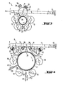
- the processing station 5 is particularly important for the present invention, which is shown on an enlarged scale, particularly in FIGS. 3 and 4, for the case in which the workpieces 2 are to be perforated.
- the device 1 and in particular its work station 5 have a holder for the workpiece 2 to be described in more detail and at least one (FIG. 3) or two (FIG. 4) with perforation needles 8 or the like.
- Carrier body 9 occupied.
- drive means are provided for repeatedly inserting the needles or styli 8 into the surface or wall of the hollow body 2.
- rotatable support rollers or rings 10 are provided as holders for the workpiece 2, and the needle carrier 9 is also a rotating body, the circumference of which is occupied by the needles 8 or the like is and whose axis of rotation runs parallel to the axes of rotation of the support rollers 10 of the hollow body 2 to be perforated and also to the axis thereof. It can be seen in FIGS. 3 and 4 that in the use position the needle carrier 9 with its axis approximates the workpiece so far is that the needles pierce and perforate the wall of the hollow body 2 at least after several revolutions.
- the needle rollers or rings 9 are pivotably mounted relative to the workpiece 2.
- a swivel arm 11 which is fixed in the device 1 via a joint 12 and can be swiveled upwards and then downwards again according to the double arrow Pf 1 from the position shown in FIGS. 3 and 4. It is clear that in the up position of this swivel arm 11, a workpiece 2 can be ejected after its processing or a new workpiece can be inserted for processing.
- the needles 8 can have any profile if the perforation is to have a specific shape.
- the support rollers 10 and also the needle carrier (s) 9 are expediently adjustable to the diameter of the hollow body 2 to be perforated, the needle rollers being adaptable by pivoting the swivel arm 11, while the support rollers can be mounted with their axes displaceable in parallel. It is advantageous that the needle carriers in particular have a drive and the carrier rollers can run along empty. However, it is also possible that at least one of the support rollers 10 has a drive, not shown.
- a gear 13 or the like can be seen on an end face of the needle carrier rollers 9, which belongs to the drive of these needle rollers 9 or forms the drive. With this gear 13 further wheels or a chain or the like can then cooperate.
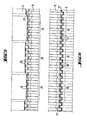
- the needle carrier 9 can be designed as a needle roller of approximately the length that corresponds to the length of the area of the workpiece 2 to be perforated, in particular that of the entire workpiece 2. It is also indicated in Fig. 2 that z. B. three workpieces can be created and processed at the same time, in particular if 2 knife blades 14 or the like are arranged in at least one space between the support rollers 10 arranged on the circumference for the rotating workpiece. Cutting tools for separating a sleeve with a predetermined length are arranged. 2, for example, three perforated sleeves 15 can be formed from a blank during processing. It can be seen in Fig. 7 that for the separation of individual sleeves 15 from pipes 16 or the like.
- a plurality of knives 14 arranged at a distance from one another are provided and that rings 17 with spaced rings 8 are preferably used for the rotary drive of the workpieces can be provided.
- the focus is on the production of individual sleeves or rings.
- additional perforating devices e.g. H.
- Carrying body 9 filled with needles 8 can be provided, which work holes into the surface of the sleeves 15 simultaneously or subsequently or before the separation.
- the shaft 18, which carries the needle rings 17, belongs to the drive of the processing station 5.
- the needles 8 may not need to pierce the surface of the sleeves 15 if it is only a question of the production of pipe pieces or sleeves 15 and whose perforation is not desired.
- support rollers 10 (not shown in detail) can be provided, these being mainly loose can run along because the needle rings 17 can take over the drive.
- supporting rollers driven with the needle rings 17 in addition to or instead of the shaft 18.
- a plurality of needle rings 17 and / or needle rollers 9 can be provided for the rotary drive and / or for the actual perforation, in particular for larger workpieces 2, these needle rings or rollers in the longitudinal direction one behind the other and / or on the circumference of the workpiece can be distributed.
- the former can be seen in FIG. 7, the latter in FIG. 4.
- the above-described device and in particular the work station 5 shown in FIGS. 3 and 4 allow a perforating process with heated needles 8 without these needles having to be connected to a heater. It is namely possible by the arrangement described above that repeated piercing or intervening at the points of the workpiece 2 to be perforated with one or more needles and that the punctures or interventions are repeated so often and so quickly that the several times in the heat the resulting perforations into the needle tips by the friction itself. Especially when perforating from Thermoplan AG - sticianm plastic existing workpieces 2 the implementation of true perforation is supported from an initially small puncture by said heating or heating and outreach possible.
- the hollow body 2 to be perforated is rotated in this perforation and the rotating body 9 occupied by the needles 8 rotates in the opposite direction, so that a kind of toothing is generated between the needles and the latter perforations are formed.
- the circumferential circle extending through the needle tips dips into the surface of the body to be perforated or even penetrates it, the speed of rotation being able to be selected so that the needle tips repeatedly immersed in the same place produce the abovementioned frictional heat. It is not important that the same needle always hits the same hole, but it is only necessary that some needle always hits the same hole.
- the rotating body 2 to be perforated can be rotated by the rotation of the needle carrier (s) 9 and the positive engagement that occurs in the process.
- the self-heating needles 8 are expediently blown on and / or treated preparatively to adjust their temperature, in particular wetted with a coolant.
- a liquid coolant can be applied, in particular brushed, by atomization or as dripping oil.
- FIGS. 3 and 4 For this purpose, one can see in FIGS. 3 and 4, in addition to the respective needle roller 9 or the like. Perforating tool, axially parallel to this, a channel 19 for blowing air with openings 20 directed against the needles 8. However, through this channel 19 and the openings 20 coolant can also be supplied.
- a brush 21 can be seen in each needle roller 9 for applying a liquid coolant to the needles 8, said brush 21 engaging with its bristles 22 in the area of at least the tips of the needles 8.
- ejector 23 is arranged opposite the attack of the needle rollers 9 or rings 17 and / or cutting knife 14 in the region of the workpiece 2.
- Fig. 3 it is shown that a single ejector is sufficient for a smaller workpiece, while it is indicated in Fig. 4 that several ejectors 23 can be provided, especially for larger workpieces.
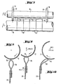
- the design and operation of the ejector 23 can be seen particularly well in FIGS. 8 to 10. It is important that the ejector 23 is connected to the pivot bearing of the needle roller 9 or the like, or at least works synchronously in such a way that when the needle roller swings away 9 of the finished workpiece 2, this is acted upon by the ejector 23 between the support rollers 10 and is lifted out of the latter.
- the ejector 23 is designed as a ruler or the like, which is mounted approximately parallel to the workpiece 2 and has an elastic narrow side 24 which acts on the workpiece 2 and extends over at least part of the workpiece length.
- the ejector 23 in the exemplary embodiment has an elastic lip 25 which has a tube-shaped or loop-shaped cross section for adaptation to workpiece movements taking place during ejection. This makes it possible to gently eject even somewhat flexible workpieces.
- 8 shows the ejector 23 initially in the rest position. When ejecting the ejector 23 is moved in the direction of arrow Pf 2, whereby the workpiece is raised.
- FIGS. 3 and 4 A side view of a schematic representation of the cutting knife (s) 14 can also be seen in FIGS. 3 and 4. It is clear that these cutting knives 14 with their cutting edge 26 are preferably at an acute angle to the surface of the workpiece 2 and preferably gradually during the cutting cut deeper into the workpiece and retractable after cutting while rotating. This retraction movement with simultaneous rotation of the workpiece can bring about an easy release of the knife from the cut formed by it and remove any burr that may occur. To separate short sleeves 15 or the like.
- Ring-shaped workpieces with knife blades 14 that are close to one another, these and in particular their cutting edges can be offset in height, so that they attack the workpiece at different times when it is inserted into the workpiece surface and do not deform it as far as possible and do not deform it generate great cutting resistance.
- Another advantage of the pulling cuts produced by the knife blades 14 described and their cutting edges 26 and the still ongoing rotary movement of the workpieces when the knife blades are pulled out of the cut is that the cutting edges can sharpen the blades again and again, so that the cutting process to a certain extent is self-sharpening.
- the support rollers 10 may have an analog counter-profiling.
- 5 shows an example in which a strongly profiled support roller 10 engages a workpiece with relatively wide shafts.
- FIG. 6 shows a solution in which the support roller 10 also shown in FIG. 5 for workpieces having ring-shaped profiles 27 has zones 28 and 29 with groups of stronger counter-profiles 30 and those with weaker counter-profiles 31. It can be clearly seen how the stronger profiles 30 fully engage in the profiles 27 of the workpiece, while the weaker counter profiles 31 only partially protrude into the profiles 27, so that the workpiece can adapt well to the support roller in the event of inaccuracies.
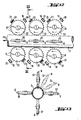
- FIGS. 12 and 13 A modified embodiment of a work station for perforating tubes 2 of any shape in cross section is shown schematically in FIGS. 12 and 13.
- at least one needle wheel in the exemplary embodiment several needle wheels arranged at an angle to one another on the circumference of the hollow body 2 to be perforated, the axes of rotation of which are transverse is arranged to the feed direction of the workpiece 2 indicated by the arrow Pf 4.
- These needle wheels 32 several of which are arranged one behind the other in such a way that their needles 8 can also repeatedly enter the same perforations, cause the workpiece feed if one or more of them are driven.
- the axes of these needle wheels 32 are arranged at right angles to the feed of the workpiece 2 to be perforated and they are also distributed over the circumference of this workpiece 2 so that corresponding rows of per forations can arise.
- a conveyor belt 34 running obliquely in the direction of advance against the needle field 33 is provided, which on the opposite side of the needle field 33 is frictionally and / or positively on the hollow bodies by means of projections, tips or the like 2 attacks and presses them gradually in the direction of advance as they roll onto the needles 8.
- a carrier 35 of this conveyor belt 34 can be adjusted according to the double arrows Pf 7 with regard to its total distance from the needle field 33 and also with regard to its inclined position.
- At least one rotating circular knife 36 and / or at least one is preferably pivotable for the separation of sleeves 15 which can be advanced by means of the conveyor belt 34 acting on their circumference bare knife blade 41 shown in Fig. 11 is provided.
- the needles 8 can preferably be cooled with a gaseous or liquid coolant through bores 37 in their carrier 38.
- the conveyor belt 34 which is designed as a friction belt, can be pressed against the needle field 33 by means of a pressure plate 39, in order to ensure the desired unrolling of the workpieces despite the resistance in the perforating and / or cutting process.
- the conveyor belt In particular for changing the inclined position of the conveyor belt, it can be pivotably mounted on an axis 40 running on one side about an axis 40 parallel to the needle plane. It can be seen that the carrier 35 also carries the knife 36.
Abstract
Description
Die Erfindung betrifft ein Verfahren zum Perforieren und/ oder Abschneiden rundlauffähiger bzw. rotationssymmetrischer Hohlkörper an deren Wandung, insbesondere von Wickelträgern wie z. B. Textilhülsen vorzugsweise aus Kunststoff. Sie betrifft ferner eine Vorrichtung insbesondere zur Durchführung des Verfahrens.The invention relates to a method for perforating and / or cutting concentric or rotationally symmetrical hollow body on the wall, in particular of winding carriers such. B. textile sleeves preferably made of plastic. It also relates to a device, in particular for performing the method.
Aus der DE-PS 25 06 512 ist eine rotationssymmetrische Textilhülse aus thermoplastischem Werkstoff bekannt, die in radialer und auch axialer Richtung verformbar ist. Der Textilwickel kann dabei einer Naß- und/oder Wärmebehandlung unterzogen werden, wobei für die Durchlässigkeit der Flotte Perforationen in der Wandung der Textilhülse vorgesehen sind.From DE-PS 25 06 512 a rotationally symmetrical textile sleeve made of thermoplastic material is known, which is deformable in the radial and also in the axial direction. The textile winding can be subjected to a wet and / or heat treatment, perforations being provided in the wall of the textile sleeve for the permeability of the liquor.
Darüber hinaus gibt es zahlreiche Fälle, in denen Rohrabschnitte von einem zunächst längeren Rohling abzuschneiden sind. Dies gilt z. B. für Papprohre, Tapetenwickel usw. Vorteilhaft ist es auch, wenn solche Hülsen bei ihrer Fertigung zunächst geblasen werden können, wobei eine kontinuierliche Fertigung von Rohren oder eine intermittierende Fertigung von geblasenen Hohlkörpern bekannt ist, bei denen dann der Boden und das Ansatzstück für die eingeblasene Luft nachträglich abgeschnitten werden müssen.In addition, there are numerous cases in which pipe sections have to be cut from an initially longer blank. This applies e.g. B. for cardboard tubes, wallpaper wraps, etc. It is also advantageous if such sleeves can be blown during their manufacture, a continuous manufacture of tubes or an intermittent manufacture of blown hollow bodies is known, in which case the bottom and the endpiece for the blown air must be cut off subsequently.
Der Erfindung liegt in erster Linie die Aufgabe zugrunde, ein Verfahren zu schaffen, mit dem Hülsen auf einfache Weise schnell und wirtschaftlich perforiert und/oder gegebenenfalls auf ihre richtige Länge zugeschnitten werden können.The primary object of the invention is to provide a method with which sleeves can be perforated quickly and economically in a simple manner and / or, if necessary, cut to their correct length.
Zur Lösung dieser Aufgabe ist ein Verfahren zum Perforieren der eingangs erwähnten Art vor allem dadurch gekennzeichnet, daß an den zu perforierenden Stellen des Werkstückes wiederholt mit einer oder mehreren Nadeln, Stempeln, Stiften od. dgl. eingestochen wird und daß die Einstiche so oft und so schnell hintereinander wiederholt werden, daß sich die mehrmals in die entstehenden Lochungen eintauchenden Nadelspitzen od. dgl. durch Reibung selbst erwärmen.To solve this problem, a method for perforating the type mentioned above is characterized above all by repeatedly stabbing at the points of the workpiece to be perforated with one or more needles, stamps, pins or the like, and in that the punctures are carried out as often and so can be repeated quickly in succession that the needle tips or the like, which plunge into the perforations several times, heat themselves due to friction.
Zwar ist es beim Perforieren von Folien schon bekannt, erhitzte Nadeln einzusetzen. Dabei sind jedoch aufwendige Heizvorrichtungen erforderlich, die zudem eine eigene Energieversorgung benötigen. Die Erfindung nutzt demgegenüber die beim Einstechen und wiederholtem Eintauchen in eine Lochung entstehende Reibungshitze aus, um eine zunächst kleine Lochung zu einer Perforation zu machen.When perforating foils, it is already known to use heated needles. However, expensive heating devices are required, which also require their own energy supply. In contrast, the invention makes use of the frictional heat generated during piercing and repeated dipping into a perforation in order to make an initially small perforation into a perforation.
Besonders zweckmäßig ist es, wenn der zu perforierende Hohlkörper bei der Perforierung gedreht wurd und wenn wenigstens ein mit Nadeln od. dgl. besetzter, ebenfalls rotierender Drehkörper in Gegendrehung versetzt wird, wobei der durch die Nadelspitzen od. dgl. verlaufende Umfangskreis in die Oberfläche des zu perforierenden Körpers eintaucht und wobei die Drehzahl so gewählt wird, daß die wiederholt in dieselben Stellen eintauchenden Nadelspitzen od. dgl. durch Reibung erwärmt werden. Dabei ergibt sich bereits beim ersten Einstechen eine Art Verzahnung zwischen dem zu perforierenden Hohlkörper und dem mit den Nadeln besetzten Drehkörper. Auf diese Weise kann sehr leicht erreicht werden, daß bei mehreren Umdrehungen immer wieder Nadelspitzen in Lochungen treffen. Eine zu geringe oder zu starke Erhitzung kann durch die erwähnte Drehzahl-Wahl vermieden werden.It is particularly expedient if the hollow body to be perforated has been rotated during the perforation and if at least one rotating body, which is also equipped with needles or the like and is also rotated, is set in counter-rotation, the circumferential circle running through the needle tips or the like into the surface of the immersed body to be perforated and the speed is selected so that the needle tips or the like repeatedly immersed in the same places are heated by friction. This results in a kind of toothing between the hollow body to be perforated and the first piercing rotating body with the needles. In this way it can be very easily achieved that needle tips repeatedly hit holes in the course of several revolutions. Too little or too much heating can be avoided by the mentioned speed selection.
Der zu perforierende Drehkörper kann durch die Drehung des oder der Nadelträger und den zeitweiligen Formschluß der in ihn einstechenden Nadeln od. dgl. gedreht werden. Dadurch genügt es, wenn nur wenigstens einer der Nadelträger mit einem Antrieb versehen ist.The rotating body to be perforated can be rotated or the like by the rotation of the needle carrier or carriers and the temporary positive locking of the needles piercing it. It is therefore sufficient if only at least one of the needle carriers is provided with a drive.
Die sich selbst erwärmenden Nadeln od. dgl. können zur Einstellung ihrer Temperatur angeblasen und/oder präparativ behandelt, insbesondere mit einem Kühlmittel benetzt werden. Dabei kann das flüssige Kühlmittel durch Vernebelung oder als Tropföl aufgetragen, insbesondere aufgebürstet werden.The self-heating needles or the like can be blown to adjust their temperature and / or treated preparatively, in particular wetted with a coolant. The liquid coolant can be applied, in particular brushed, by atomizing or as dripping oil.
Eine Ausgestaltung der Erfindung von eigener schutzwürdiger Bedeutung kann darin bestehen, dap ein kontinuierlich oder intermittierend geblasener Hohlkörper gedreht und an seinen späteren Stirnseiten abgeschnitten wird, vorzugsweise gleichzeitig mit oder nach einem'Perforiervorgang. Auf diese Weise können Hülsen vorbestimmter Länge von dem jeweiligen Rohling, der entweder ein längeres Rohr oder aber ein flaschenförmiges Teil sein kann, abgeschnitten. Besonders vorteilhaft ist es dabei, wenn die Drehung dieses Rohlings sowohl für das vorbeschriebene Perforier-Verfahren als auch zum Abschneiden ausgenutzt wird. In gleicher Weise können jedoch auch Hülsen vorbestimmter Länge gefertigt werden, die keine Perforierung erhalten. Dabei könnte deren Drehung dennoch mit Hilfe eines Nadel-Rades od. dgl. erfolgen, wobei dann die Nadeln nicht durch die gesamte Oberfläche des Körpers hindurchtreten müssen.An embodiment of the invention of its own worthy of protection can consist in rotating a continuously or intermittently blown hollow body and cutting it off at its later end faces, preferably simultaneously with or after a perforation process. In this way, sleeves of a predetermined length can be cut off from the respective blank, which can either be a longer tube or a bottle-shaped part. It is particularly advantageous if the rotation of this blank is used both for the above-described perforation process and for cutting off. In the same way, however, sleeves of a predetermined length can also be produced that do not receive any perforation. Their rotation could nevertheless take place with the aid of a needle wheel or the like, the needles not then through the entire surface of the body have to step through.
Der Erfindung liegt auch die Aufgabe zugrunde, eine möglichst zweckmäßige Vorrichtung zum Perforieren und/oder Zuschneiden rotationssymmetrischer, vorzugsweise hülsenförmiger Hohlkörper insbesondere aus Kunststoff zu schaffen.The invention is also based on the object of creating a device for perforating and / or cutting rotationally symmetrical, preferably sleeve-shaped hollow bodies, in particular made of plastic, which is as practical as possible.
Eine zur Lösung dieser Aufgabe geeignete Vorrichtung kann dabei dadurch gekennzeichnet sein, daß sie eine Halterung für das Werkstück sowie wenigstens einen mit Perforationsnadeln, -stempeln, -stiften od. dgl. besetzten Tragkörper aufweist und daß Antriebsmittel zum wiederholten Einstechen der Nadeln od. dgl. in die Oberfläche bzw. Wandung des Hohlkörpers vorgesehen sind. Als Halterung für das Werkstück können dabei an dessen Außenumfang angreifende, drehbare Tragwalzen vorgesehen sein und der oder die Nadelträger können ein Drehkörper sein, dessen Umfang mit Nadeln od. dgl. besetzt ist und dessen Drehachse parallel zu denen der Tragwalzen und des zu perforierenden Hohlkörpers verläuft. Vor allem die Nadelwalzen können dabei relativ zu dem Werkstück schwenkbar gelagert sein, um auch außer Eingriff gebracht werden zu können, wenn das Werkstück fertig ist, wobei gleichzeitig das Einlegen eines neuen Werkstückes dann erleichtert wird. Es sei erwähnt, daß die Nadeln od. dgl. Stichwerkzeuge je nach gewünschter Form der Perforierung auch profiliert sein können.A device suitable for solving this task can be characterized in that it has a holder for the workpiece and at least one support body filled with perforation needles, punches, pins or the like, and that drive means for repeated piercing of the needles or the like. are provided in the surface or wall of the hollow body. As a holder for the workpiece, there can be provided on the outer periphery, rotating support rollers, and the needle carrier (s) can be a rotating body, the periphery of which is occupied by needles or the like, and the axis of rotation of which runs parallel to those of the supporting rollers and the hollow body to be perforated . In particular, the needle rollers can be pivoted relative to the workpiece so that they can also be disengaged when the workpiece is finished, at the same time making it easier to insert a new workpiece. It should be mentioned that the needles or the like. Stitching tools can also be profiled depending on the desired shape of the perforation.
Weitere Ausgestaltungen hinsichtlich der Tragwalzen und deren Anpaßbarkeit an Werkstücke unterschiedlicher Durchmesser sowie der Nadelträger sind Gegenstand weiterer Ansprüche.Further designs with regard to the support rollers and their adaptability to workpieces of different diameters and the needle carrier are the subject of further claims.
Eine Ausgestaltung der erfindungsgemäßen Vorrichtung von eigener schutzwürdiger Bedeutung kann darin bestehen, daß in wenigstens einem Zwischenraum zwischen den am Umfang angeordneten Tragwalzen für das rotierende Werkstück zumindest eine Messerklinge od. dgl. Schneidwerkzeug zum Abtrennen einer Hülse od. dgl. mit vorbestimmter Länge von einem Rohling angeordnet ist. Dabei kann eine solche Schneidvorrichtung entweder zusätzlich zu Perforier-Nadeln od. dgl. oder auch in einer Vorrichtung ohne solche Perforier-Vorrichtungen angeordnet sein, wenn die Vorrichtung nur zur Herstellung von Hülsen vorbestimmter Länge gedacht ist.An embodiment of the device according to the invention from Its own worthy of protection may consist in that at least one knife blade or the like. Cutting tool for severing a sleeve or the like with a predetermined length from a blank is arranged in at least one space between the support rollers arranged on the circumference for the rotating workpiece. Such a cutting device can be arranged either in addition to perforating needles or the like, or also in a device without such perforating devices if the device is only intended for the production of sleeves of a predetermined length.
Für das Abtrennen einzelner Hülsen von Rohren od. dgl. Rohlingen können auch mehrere im Abstand zueinander angeordnete Messer od. dgl. vorgesehen sein und es können mit Nadeln besetzte, mit Abstand zueinander angeordnete Ringe od.dgl. vorzugsweise für den Drehantrieb der Werkstücke vorgesehen sein. In diesem Falle können diese Nadel-Ringe die Werkstücke zahnradartig antreiben, wobei dadurch die Funktion dieser Nadelträger bereits erfüllt sein kann oder wobei die Nadeln so tief einstechen, daß gleichzeitig eine Perforierung entsteht.For the separation of individual sleeves from pipes or the like blanks, a plurality of knives or the like which are arranged at a distance from one another can also be provided and rings or the like which are fitted with needles and which are arranged at a distance from one another can be provided. preferably be provided for the rotary drive of the workpieces. In this case, these needle rings can drive the workpieces in the manner of a gearwheel, whereby the function of these needle carriers can already be fulfilled, or the needles penetrate so deeply that a perforation occurs at the same time.
Insbesondere für größere Werkstücke können dabei mehrere Nadelringe und/oder Nadelwalzen für den Drehantrieb und/ oder eine Perforation vorgesehen sein.In particular for larger workpieces, a plurality of needle rings and / or needle rollers can be provided for the rotary drive and / or perforation.
Es ist jedoch auch möglich, daß wenigstens eine der Tragwalzen mit einem Antrieb verbunden ist. Dadurch kann entweder ein Drehantrieb, der von Nadelwalzen ausgeht, unterstützt oder aber ersetzt werden, was vor allem dann zweckmäßig ist, wenn die Vorrichtung in erster Linie zum Abtrennen von Hülsen gedacht ist.However, it is also possible for at least one of the support rollers to be connected to a drive. This can either support or replace a rotary drive emanating from needle rollers, which is particularly expedient if the device is primarily intended for separating sleeves.
Eine weitere Ausgestaltung der erfindungsgemäßen Vorrichtung von eigener schutzwürdiger Bedeutung kann darin bestehen, daß neben der Nadelwalze od. dgl. Perforier-Vorrichtung vorzugsweise achsparallel zu dieser ein Kanal für Anblasluft mit gegen die Nadeln od. dgl. gerichteten öffnungen und/oder für die Zufuhr einer Kühlflüssigkeit vorgesehen sind. Dadurch läßt sich neben der Temperierung durch eine bestimmte Drehzahl eine überhitzung der Nadeln mit Hilfe eines Kühlmediums vermeiden. Insbesondere zum Auftragen eines flüssigen Kühlmittels auf die Nadeln od. dgl. kann wenigstens eine mit ihren Borsten zumindest in den Bereich der Nadelspitzen od. dgl. eingreifende Bürste od. dgl. vorgesehen sein.Another embodiment of the device according to the invention device of its own worthy of protection may consist in that, in addition to the needle roller or the like. Perforating device, preferably a channel for blowing air with openings directed against the needles or the like and / or for the supply of a cooling liquid are provided axially parallel to the latter. As a result, in addition to the temperature control by a certain speed, overheating of the needles with the aid of a cooling medium can be avoided. In particular, for applying a liquid coolant to the needles or the like, at least one brush or the like which engages with its bristles at least in the area of the needle tips or the like can be provided.
Weitere Ausgestaltungen der Erfindung insbesondere bezüglich eines Auswerfers, der das fertig bearbeitete Werkstück aus dem Bereich der Tragwalzen ausheben kann, sind ebenso wie weitere Ausgestaltungen bezüglich des Trennmessers Gegenstand weiterer Ansprüche.Further refinements of the invention, in particular with regard to an ejector, which can lift the finished workpiece out of the area of the support rollers, are the subject of further claims, as are further refinements with respect to the cutting knife.
Zum Perforieren und/oder Abtrennen von Werkstücken mit profilierter Oberfläche können die Tragwalzen eine analoge Gegenprofilierung aufweisen. Insbesondere die Textilhülsen gemäß DE-PS 25 06 512 sollen vor allem eine wellige Oberfläche haben können, um in radialer und auch axialer Richtung eine Nachgiebigkeit ihrer Oberfläche zu erlauben. Bei der Perforierung einer solchen Hülse ist es zweckmäßig, wenn die vorerwähnte Maßnahme ergriffen wird, daß nämlich Tragwalzen mit Gegenprofilierungen verwendet werden. Dabei können die Tragwalzen für ringförmig angeordnete Profilierungen aufweisende Werkstücke Zonen mit Gruppen von stärkeren Gegenprofilierungen und solche mit schwächer ausgebildeten Gegenprofilierungen aufweisen. Dies erlaubt es einer solchen profilierten Hülse, sich auch bei geringen Maßabweichungen an die Profilierungen der Tragwalzen anzupassen, da vor allem die schwächer ausgebildeten Gegenprofilierungen nicht vollständig in die Hülsenprofilierung eingreifen und dieser somit etwas Bewegungsfreiheit in axialer und/oder radialer Richtung geben.For perforating and / or separating workpieces with a profiled surface, the support rollers can have an analog counter-profile. In particular, the textile sleeves according to DE-PS 25 06 512 should above all be able to have a wavy surface in order to allow their surface to be flexible in the radial and also in the axial direction. When perforating such a sleeve, it is expedient if the aforementioned measure is taken, namely that support rollers with counter-profiles are used. In this case, the support rollers for workpieces having ring-shaped profiles can have zones with groups of stronger counter-profiles and those with weaker counter-profiles. This allows such a profiled sleeve to adapt to the profiling of the support rollers even with small dimensional deviations, since above all the weaker ones trained counter-profiles do not fully engage in the sleeve profile and thus give it some freedom of movement in the axial and / or radial direction.
Es wurde bereits erwähnt, daß die Nadel-Walzen oder -räder mit ihren Achsen parallel zu einem zu perforierenden Werkstück angeordnet sein können. Bei einer abgewandelten Ausführungsform der Erfindung, die wiederum eigene schutzwürdige Bedeutung hat, ist es jedoch möglich, daß zum Perforieren von Hohlkörpern, vorzugsweise von unmittelbar aus einer Extrudiervorrichtung od. dgl. austretenden Hohlkörpern zumindest ein Nadelrad od. dgl., vorzugsweise mehrere im Winkel zueinander angeordnete Nadelräder vorgesehen sind, deren Drehachse quer, vorzugsweise rechtwinklig zur Vorschubrichtung des Werkstückes angeordnet sind. Dabei können zusätzlich zu diesen Nadelrädern auch solche mit parallel zu der Werkstückachse verlaufende Nadelräder vorgesehen sein. Insbesondere mit ihren Achsen etwas schräg zum Vorschub und zur Werkstückachse stehende Nadelräder können dabei eventuell auch schraubenlinienförmige Perforierungen erzeugen.It has already been mentioned that the needle rollers or wheels can be arranged with their axes parallel to a workpiece to be perforated. In a modified embodiment of the invention, which in turn has its own worthy of protection, it is possible that for perforating hollow bodies, preferably hollow bodies emerging directly from an extrusion device or the like, at least one needle wheel or the like, preferably several at an angle to one another arranged needle wheels are provided, the axis of rotation of which are arranged transversely, preferably at right angles to the feed direction of the workpiece. In addition to these pinwheels, pinwheels running parallel to the workpiece axis can also be provided. In particular, their axes, which are somewhat oblique to the feed and to the workpiece axis, can possibly also produce helical perforations.
Eine abgewandelte Vorrichtung insbesondere zur Durchführung des eingangs geschilderten Verfahrens kann darin bestehen, daß zum Perforieren von vorzugsweise rotationssymmetrischen Körpern feststehende, insbesondere in einer Ebene liegende Nadelfelder vorgesehen sind, über die die zu perforierenden Körper abrollbar sind. Dadurch läßt sich auch bei genügender Rollgeschwindigkeit erreichen, daß die Nadelspitzen od. dgl. immer wieder in die zunächst kleinen Lochungen eintreten und sich erhitzen, so daß allmählich eine entsprechend große Perforierung gebildet werden kann.A modified device, in particular for carrying out the method described at the outset, can consist in that fixed, in particular in one plane, needle fields are provided for perforating preferably rotationally symmetrical bodies, by means of which the bodies to be perforated can be unrolled. As a result, even with sufficient rolling speed, the needle tips or the like can repeatedly enter and heat up in the initially small perforations, so that a correspondingly large perforation can gradually be formed.
In all diesen Fällen wird die Anzahl der Tritte einer Nadelspitze in dieselbe Stelle so groß gewählt, daß die Perforierung die gewünschte Größe erreicht.In all of these cases, the number of times a needle point is kicked into the same location is chosen so large that the perforation reaches the desired size.
Weitere Ausgestaltungen der Vorrichtung, bei welcher das Werkstück über ein Nadelfeld gerollt wird, insbesondere der dabei zum Rollen verwendete Mechanismus, zweckmäßigerweise ein schräg gegen das Nadelfeld laufendes Transportband, sind ebenfalls Gegenstand weiterer Ansprüche.Further embodiments of the device in which the workpiece is rolled over a needle field, in particular the mechanism used for rolling, expediently a conveyor belt running obliquely against the needle field, are also the subject of further claims.
Nachstehend ist die Erfindung mit ihren ihr als wesentlich zugehörenden Einzelheiten anhand der Zeichnung noch näher beschrieben. Es zeigt in zum Teil schematisierter Darstellung:
- Fig. 1 eine Stirnansicht und
- Fig. 2 eine Draufsicht einer erfindungsgemäßen Vorrichtung, mit der Hülsen erfindungsgemäß perforiert und/oder zurechtgeschnitten werden können,
- Fig. 3 in vergrößertem Maßstab in Stirnansicht eine Perforierwalze beim Bearbeiten eines von Tragwalzen gehaltenen Werkstückes,
- Fig. 4 eine der Fig. 3 entsprechende Darstellung einer Vorrichtung für Werkstücke größeren Durchmessers mit zwei Nadelwalzen od. dgl.,
- Fig. 5 eine Seitenansicht einer profilierten Tragwalze für ein mit breiten Wellen versehenes Werkstück,
- Fig. 6 eine der Fig. 5 entsprechende Darstellung, wobei das Werkstück eine engere, der Tragwalze entsprechende Profilierung aufweist,
- Fig. 7 eine Teil-Seitenansicht einer Vorrichtung mit Nadelringen insbesondere für den Antrieb des Werkstückes sowie vorzugsweise mehreren dazwischen angeordneten Schneidwerkzeugen zum Herstellen von Hülsen oder Ringen,
- Fig. 8
bis 10 die Funktion eines mit einer elastischen Arbeitskante versehenen Auswerfers für ein Werkstück, - Fig. 11 eine abgewandelte Vorrichtung, bei der ein Werkstück mittels eines von oben an ihm angreifenden Transportbandes über ein feststehendes Nadelfeld gerollt und dabei vorzugsweise immer stärker angepreßt wird,
- Fig. 12 ein Ausführungsbeispiel, bei dem die Achsen der Nadelträger quer, insbesondere rechtwinklig zu der des Werkstückes stehen und
- Fig. 13 eine Stirnansicht der in Fig. 12 dargestellten Vorrichtung.
- Fig. 1 is an end view and
- 2 shows a top view of a device according to the invention, with which sleeves can be perforated and / or cut to size according to the invention,
- 3 is an enlarged front view of a perforating roller when machining a workpiece held by support rollers,
- 4 a representation corresponding to FIG. 3 of a device for workpieces of larger diameter with two needle rollers or the like,
- 5 is a side view of a profiled support roller for a workpiece provided with wide shafts,
- 6 shows a representation corresponding to FIG. 5, the workpiece having a narrower profile corresponding to the support roller,
- 7 shows a partial side view of a device with needle rings, in particular for driving the workpiece, and preferably a plurality of cutting tools arranged therebetween for producing sleeves or rings,
- 8 to 10 the function of an ejector provided with an elastic working edge for a workpiece,
- 11 shows a modified device in which a workpiece is rolled over a stationary needle field by means of a conveyor belt acting on it from above and is preferably pressed ever more strongly,
- Fig. 12 shows an embodiment in which the axes of the needle carrier are transverse, in particular at right angles to that of the workpiece and
- Fig. 13 is an end view of the device shown in Fig. 12.
Eine im ganzen mit 1 bezeichnete Vorrichtung dient in erster Linie dazu, rundlauffähige bzw. rotationssymmetrische Hohlkörper oder Werkstücke 2, z. B. Textilhülsen, zu perforieren. Zusätzlich oder statt dessen kann die Vorrichtung 1 gemäß der folgenden Beschreibung jedoch auch dazu ausgestaltet oder eingerichtet sein, solche Werkstücke 2 von kontinuierlich oder intermittierend geblasenen Hohlkörpern abzutrennen und unter Umständen auch zu mehreren Hülsen oder Ringen zu zerschneiden. Insgesamt erlaubt die im folgenden beschriebene Vorrichtung 1 also die Herstellung von Ringen oder Hülsen und/oder deren Perforierung. Man erkennt in der Vorrichtung 1 im wesentlichen ein Magazin 3, aus welchem die Rohlinge über eine Führung 4 der eigentlichen, im folgenden näher zu beschreibenden Bearbeitung zugeführt werden. Die Bearbeitungsstation ist in Fig. 1 im ganzen mit 5 bezeichnet.A device designated as a whole with 1 is primarily used for concentric or rotationally symmetrical hollow bodies or
Im Anschluß an die Bearbeitungsstation 5 etwa in Fortsetzung der Führung 4 ist eine Rutsche 6 od. dgl. angeordnet, über die die fertigen Werkstücke 2 abgeführt werden können. In Fig. 2 ist angedeutet, daß die Werkstücke 2 dabei z. B. auf ein Förderband 7 gelangen können.Following the
Wesentlich für die vorliegende Erfindung ist vor allem die Bearbeitungsstation 5, die vor allem in den Figuren 3 und 4 in vergrößertem Maßstab für den Fall dargestellt ist, bei dem die Werkstücke 2 perforiert werden sollen.The
In Fig. 3 und 4 erkennt man demgemäß vor allem, daß die Vorrichtung 1 und insbesondere ihre Arbeitsstation 5 eine noch näher zu beschreibende Halterung für das Werkstück 2 sowie wenigstens einen (Fig. 3) oder zwei (Fig. 4) mit Perforationsnadeln 8 od. dgl. Sticheln besetzten Tragkörper 9 aufweist. Dabei sind Antriebsmittel zum wiederholten Einstechen der Nadeln oder Stichel 8 in die Oberfläche bzw. Wandung des Hohlkörpers 2 vorgesehen. In diesem Ausführungsbeispiel gemäß den Figuren 3 und 4 sind als Halterung für das Werkstück 2 an dessen Außenumfang angreifende, drehbare Tragwalzen oder -ringe 10 vorgesehen und der oder die Nadelträger 9 ist ebenfalls ein Drehkörper, dessen Umfang mit den Nadeln 8 od. dgl. besetzt ist und dessen Drehachse parallel zu den Drehachsen der Tragwalzen 10 des zu perforierenden Hohlkörpers 2 und auch zu dessen Achse verläuft. Man erkennt in den Figuren 3 und 4, daß dabei in Gebrauchsstellung der Nadelträger 9 mit seiner Achse dem Werkstück jeweils so weit angenähert ist, daß die Nadeln zumindest nach mehreren Umläufen die Wandung des Hohlkörpers 2 durchbohren und perforieren.3 and 4, it can be seen above all that the device 1 and in particular its
Die Nadelwalzen oder -ringe 9 sind im Ausführungsbeispiel relativ zu dem Werkstück 2 schwenkbar gelagert. Man erkennt deutlich einen Schwenkarm 11, der über ein Gelenk 12 in der Vorrichtung 1 fixiert ist und gemäß dem Doppelpfeil Pf 1 aus der in den Figuren 3 und 4 dargestellten Lage nach oben und danach auch wieder nach unten verschwenkt werden kann. Es leuchtet ein, daß in Obenstellung dieses Schwenkarmes 11 ein Werkstück 2 nach seiner Bearbeitung ausgeworfen bzw. ein neues Werkstück für die Bearbeitung eingelegt werden kann.In the exemplary embodiment, the needle rollers or rings 9 are pivotably mounted relative to the
Es sei erwähnt, daß die Nadeln 8 eine beliebige Profilierung haben können, falls die Perforierung eine bestimmte Form erhalten soll.It should be mentioned that the
Die Tragwalzen 10 und auch der oder die Nadelträger 9 sind zweckmäßigerweise auf den Durchmesser des zu perforierenden Hohlkörpers 2 einstellbar, wobei die Nadelwalzen durch Verschwenkung des Schwenkarmes 11 anpaßbar sind, während die Tragwalzen mit ihren Achsen parallel verschiebbar gelagert sein können. Dabei ist es vorteilhaft, daß vor allem die Nadelträger einen Antrieb haben und die Tragwalzen leer mitlaufen können. Es ist jedoch auch möglich, daß wenigstens eine der Tragwalzen 10 einen nicht näher dargestellten Antrieb aufweist.The
In Fig. 2 kann man an einer Stirnseite der Nadelträgerwalzen 9 ein Zahnrad 13 od. dgl. erkennen, das zum Antrieb dieser Nadelwalzen 9 gehört bzw. den Antrieb bildet. Mit diesem Zahnrad 13 können dann weitere Räder oder auch eine Kette od. dgl. zusammenwirken.2, a gear 13 or the like can be seen on an end face of the
In Fig. 2 ist ferner angedeutet, daß der Nadelträger 9 als Nadelwalze von etwa der Länge ausgebildet sein kann, die der Länge des zu perforierenden Bereiches des Werkstückes 2, insbesondere also der des ganzen Werkstückes 2 entspricht. Dabei ist in Fig. 2 zusätzlich angedeutet, daß z. B. drei Werkstücke gleichzeitig entstehen und bearbeitet werden können, insbesondere wenn in wenigstens einem Zwischenraum zwischen den am Umfang angeordneten Tragwalzen 10 für das rotierende Werkstück 2 Messerklingen 14 od. dgl. Schneidwerkzeuge zum Abtrennen einer Hülse mit vorbestimmter Länge angeordnet sind. Gemäß Fig. 2 können beispielsweise aus einem Rohling während der Bearbeitung drei perforierte Hülsen 15 gebildet werden. Dabei erkennt man in Fig. 7, daß für die Abtrennung einzelner Hülsen 15 von Rohren 16 od. dgl. mehrere im Abstand zueinander angeordnete Messer 14 vorgesehen sind und daß mit Nadeln 8 besetzte, mit Abstand zueinander angeordnete Ringe 17 vorzugsweise für den Drehantrieb der Werkstücke vorgesehen sein können. In diesem Fall steht die Herstellung einzelner Hülsen oder Ringe im Vordergrund. Selbstverständlich könnten jedoch zusätzlich Perforier-Vorrichtungen, d. h. mit Nadeln 8 besetzte Tragkörper 9 vorgesehen sein, die gleichzeitig oder nachträglich oder vor dem Abtrennen Lochungen in die Oberfläche der Hülsen 15 einarbeiten.In Fig. 2 is also indicated that the
Die Welle 18, welche die Nadelringe 17 trägt, gehört dabei zum Antrieb der Bearbeitungsstation 5. In diesem Falle brauchen die Nadeln 8 unter Umständen die Oberfläche.der Hülsen 15 dann nicht zu durchstechen, wenn es nur auf die Herstellung von Rohrstücken oder Hülsen 15 ankommt und deren Perforierung nicht gewünscht wird.The
Auch in diesem Falle können nicht näher dargestellte Tragwalzen 10 vorgesehen sein, wobei diese vor allem lose mitlaufen können, weil die Nadelringe 17 den Antrieb übernehmen können. Es ist jedoch auch möglich, zusätzlich oder statt der Welle 18 mit den Nadelringen 17 angetriebene Tragwalzen zu verwenden.In this case too, support rollers 10 (not shown in detail) can be provided, these being mainly loose can run along because the needle rings 17 can take over the drive. However, it is also possible to use supporting rollers driven with the needle rings 17 in addition to or instead of the
Sowohl beim Abtrennen einzelner Hülsen als auch bei deren Perforierung können insbesondere für größere Werkstücke 2 mehrere Nadelringe 17 und/oder Nadelwalzen 9 für den Drehantrieb und/oder für die eigentliche Perforation vorgesehen sein, wobei diese Nadelringe oder Walzen in Längsrichtung hintereinander und/oder am Umfang des Werkstückes verteilt sein können. Ersteres erkennt man in Fig. 7, letzteres in Fig. 4.Both when severing individual sleeves and when perforating them, a plurality of needle rings 17 and / or
Die vorbeschriebene Vorrichtung und insbesondere die in den Figuren 3 und 4 dargestellte Arbeitsstation 5 erlauben ein Perforier-Verfahren mit erwärmten Nadeln 8, ohne daß diese Nadeln mit einer Heizung verbunden sein müssen. Es ist nämlich durch die vorbeschriebene Anordnung möglich, daß an den zu perforierenden Stellen des Werkstükkes 2 wiederholt mit einer oder mehreren Nadeln 8 eingestochen oder eingegriffen wird und daß die Einstiche oder Eingriffe so oft und so schnell hintereinander wiederholt werden, daß sich die mehrmals in die entstehenden Lochungen eintauchenden Nadelspitzen durch die Reibung selbst erwärmen. Vor allem beim Perforieren von aus thermopla- stischem Kunststoff bestehenden Werkstücken 2 wird die Herstellung einer wirklichen Perforierung aus einem zunächst kleinen Einstich durch die erwähnte Erwärmung oder Erhitzung unterstützt und überhaupt ermöglicht.The above-described device and in particular the
Der zu perforierende Hohlkörper 2 wird dabei bei dieser Perforierung gedreht und der mit den Nadeln 8 besetzte Drehkörper 9 dreht sich in Gegenrichtung, so daß eine Art Verzahnung zwischen den Nadeln und den von diesen erzeugten Lochungen gebildet wird. Der durch die Nadelspitzen verlaufende Umfangskreis taucht dabei in die Oberfläche des zu perforierenden Körpers ein oder durchdringt sie sogar, wobei die Drehzahl so gewählt werden kann, daß die wiederholt in dieselbe Stelle eintauchenden Nadelspitzen die erwähnte Reibungshitze erzeugen. Dabei kommt es nicht darauf an, daß immer tatsächlich dieselbe Nadel in dasselbe Loch trifft, sondern es ist lediglich notwendig, daß immer an derselben Lochung irgendeine Nadel auftrifft. Wie bereits erwähnt, kann dabei der zu perforierende Drehkörper 2 durch die Drehung des oder der Nadelträger 9 und den dabei auftretenden Formschluß gedreht werden.The
Zweckmäßigerweise werden die sich selbst erwärmenden Nadeln 8 zur Einstellung ihrer Temperatur angeblasen und/ oder präparativ behandelt, insbesondere mit einem Kühlmittel benetzt. Ein flüssiges Kühlmittel kann dabei durch Vernebelung oder als Tropföl aufgetragen, insbesondere aufgebürstet werden.The self-
Für diesen Zweck erkennt man in den Figuren 3 und 4 neben der jeweiligen Nadelwalze 9 od. dgl. Perforier-Werkzeug achsparallel zu dieser einen Kanal 19 für Anblasluft mit gegen die Nadeln 8 gerichteten Öffnungen 20. Durch diesen Kanal 19 und die Öffnungen 20 könnte aber auch Kühlflüssigkeit zugeführt werden.For this purpose, one can see in FIGS. 3 and 4, in addition to the
Ferner erkennt man sowohl in Fig. 3 als auch in Fig. 4 bei jeder Nadelwalze 9 zum Auftragen eines flüssigen Kühlmittels auf die Nadeln 8 eine Bürste 21, die mit ihren Borsten 22 in den Bereich von zumindest den Spitzen der Nadeln 8 eingreifen.Furthermore, both in FIG. 3 and in FIG. 4, a
Es wurde bereits erwähnt, daß vor allem die Nadelwalzen 9 oder 17 vom Werkstück wegschwenkbar sind, wenn dieses bearbeitet ist und ausgeworfen werden soll. Dazu ist dem Angriff der Nadelwalzen 9 oder Ringe 17 und/oder Trennmesser 14 entgegengesetzt im Bereich des Werkstückes 2 zumindest ein Auswerfer 23 angeordnet. In Fig. 3 ist gezeigt, daß für ein kleineres Werkstück ein einziger Auswerfer genügt, während in Fig. 4 angedeutet ist, daß vor allem bei größeren Werkstücken auch mehrere Auswerfer 23 vorgesehen sein können.It has already been mentioned that especially the
Die Ausbildung und Funktionsweise des Auswerfers 23 erkennt man besonders gut in den Figuren 8 bis 10. Wichtig ist, daß der Auswerfer 23 mit der Schwenklagerung der Nadelwalze 9 od. dgl. verbunden ist oder zumindest synchron in der Weise arbeitet, daß beim Wegschwenken der Nadelwalze 9 von dem fertig bearbeiteten Werkstück 2 dieses von dem Auswerfer 23 zwischen den Tragwalzen 10 beaufschlagt und aus diesen herausgehoben wird.The design and operation of the
Im Ausführungsbeispiel ist der Auswerfer 23 als etwa parallel zum Werkstück 2 gelagertes Lineal od. dgl. Stab mit das Werkstück 2 beaufschlagender elastischer Schmalseite 24 ausgebildet und verläuft über wenigstens einen Teil der Werkstücklänge. An seinem Arbeitsrand bzw. seiner Schmalseite 24 hat dabei der Auswerfer 23 im Ausführungsbeispiel eine elastische Lippe 25, die einen Schlauch- oder schlaufenförmigen Querschnitt zur Anpassung an während des Auswerfens stattfindende Werkstückbewegungen aufweist. Dadurch ist ein schonendes Auswerfen auch etwas nachgiebiger Werkstücke möglich. Fig. 8 zeigt dabei den Auswerfer 23 zunächst in Ruhestellung. Beim Auswerfen wird der Auswerfer 23 in Richtung des Pfeiles Pf 2 bewegt, wodurch das Werkstück angehoben wird. Hat dies die obere Tragwalze überwunden, rollt es seitlich über die Rutsche 6 weg, was gemäß Fig. 10 durch die biegsame hohle Lippe 25 erleichtert und unterstützt wird. Die Lippe 25 kann dieser Seitwärtsbewegung gemäß dem Pfeil Pf 3 des Werkstückes etwas folgen und dessen Zurückfallen in den Zwischenraum zwischen den Tragwalzen verhindern. Dazu trägt es bei, daß diese elastische Lippe 25 federnd elastisch ausgebildet ist.In the exemplary embodiment, the
Eine Seitenansicht einer schematisierten Darstellung des oder der Trennmesser 14 erkennt man ebenfalls in den Figuren 3 und 4. Dabei wird deutlich, daß diese Trennmesser 14 mit ihrer Schneide 26 schräg vorzugsweise unter einem spitzen Winkel zur Oberfläche des Werkstückes 2 stehen und während des Trennschnittes vorzugsweise allmählich tiefer in das Werkstück eingeführt und nach dem Durchtrennen noch während der Drehbewegung zurückziehbar sind. Diese Rückziehbewegung bei gleichzeitiger Drehung des Werkstückes kann dabei eine leichte Lösung des Messers aus dem von ihm gebildeten Schnitt bewirken und einen eventuell auftretenden Grat gleich mit entfernen. Zum Abtrennen kurzer Hülsen 15 od. dgl. ringförmiger Werkstücke mit nahe beieinanderstehenden Messerklingen 14 können diese und insbesondere deren Schneiden in der Höhe gegeneinander versetzt sein, so daß sie beim Einstechen in die Werkstückoberfläche zeitlich versetzt am Werkstück angreifen und dieses möglichst nicht verformen und keinen zu großen Schneidwiderstand erzeugen.A side view of a schematic representation of the cutting knife (s) 14 can also be seen in FIGS. 3 and 4. It is clear that these cutting
Ein weiterer Vorteil der von den beschriebenen Messerklingen 14 und deren Schneiden 26 erzeugten ziehenden Schnitte sowie der noch andauernden Drehbewegung der Werkstücke beim Herausziehen der Messerklingen aus dem Schnitt besteht darin, daß die Schnitt-Ränder die Klingen immer wieder nachschärfen können, so daß der Schneidvorgang gewissermaßen selbstschärfend ist.Another advantage of the pulling cuts produced by the
In den Figuren 5 und 6 ist dargestellt, daß zum Perforieren und/oder Abtrennen von Werkstücken 2 mit profilierter Oberfläche die Tragwalzen 10 eine analoge Gegenprofilierung aufweisen können. Dabei zeigt Fig. 5 ein Beispiel, bei dem eine stark profilierte Tragwalze 10 an einem Werkstück mit relativ breiten Wellen angreift.In Figures 5 and 6 it is shown that for perforation Ren and / or separation of
Fig. 6 zeigt eine Lösung, bei der die auch in Fig. 5 dargestellte Tragwalze 10 für ringförmig angeordnete Profilierungen 27 aufweisende Werkstücke 2 Zonen 28 und 29 mit Gruppen von stärkeren Gegenprofilierungen 30 und solche mit schwächer ausgebildeten Gegenprofilierungen 31 aufweist. Man erkennt deutlich, wie die stärkeren Profilierungen 30 voll in die Profilierungen 27 des Werkstückes eingreifen, während die schwächeren Gegenprofile 31 nur teilweise in die Profilierungen 27 ragen, so daß hier bei Ungenauigkeiten das Werkstück sich gut an die Tragwalze anpassen kann.FIG. 6 shows a solution in which the
Eine abgewandelte Ausführungsform einer Arbeitsstation zum Perforieren von im Querschnitt beliebig geformten Rohren 2 zeigt in schematisierter Darstellung Fig. 12 und 13. Dabei ist wenigstens ein Nadelrad, im Ausführungsbeispiel mehrere im Winkel zueinander am Umfang des zu perforierenden Hohlkörpers 2 angeordneten Nadelräder vorgesehen, deren Drehachsen quer zu der durch den Pfeil Pf 4 angedeuteten Vorschubrichtung des Werkstückes 2 angeordnet ist. Diese Nadelräder 32, von denen mehrere so hintereinander angeordnet sind, daß ihre Nadeln 8 auch jeweils wiederholt in dieselben Lochungen eintreten können, bewirken dabei, sofern eines oder mehrere von ihnen angetrieben sind, den Werkstückvorschub. Im Ausführungsbeispiel sind die Achsen dieser Nadelräder 32 rechtwinklig zum Vorschub des zu perforierenden Werkstückes 2 angeordnet und sie sind außerdem am Umfang dieses Werkstückes 2 so verteilt, daß entsprechende Reihen von Perforationen entstehen können.A modified embodiment of a work station for perforating
Bei etwas schräger angeordneten Drehachsen der Nadelräder 32 können unter Umständen auf Schraubenlinien liegende Perforierungen erzeugt werden.If the axes of rotation of the
Das vorstehend beschriebene Verfahren zum Perforieren, welches in erster Linie darin besteht, daß Madeln mehrmals so schnell hintereinander in jeweils dieselben Lochungen eintreten, daß auch Reibungswärme entsteht, kann auch mit Hilfe einer in Fig. 11 dargestellten Vorrichtung durchgeführt werden. Dabei sind in diesem Falle ein oder mehrere im wesentlichen ebene Nadelfelder 33 mit feststehenden Nadeln 8 vorgesehen, über die die zu perforierenden Werkstücke 2 abrollbar sind. Man erkennt deutlich, wie in Fig. 11 von deren rechtem Rand ein Werkstück 2 allmählich nach links, also in Richtung der Pfeile Pf 5 bewegt wird und dabei gemäß den Pfeilen Pf 6 rollt.The above-described method for perforating, which consists primarily in the fact that Madeln enter the same perforations several times in succession so quickly that frictional heat also arises, can also be carried out with the aid of a device shown in FIG. In this case, one or more essentially flat needle fields 33 with fixed
Zum Abrollen der zu perforierenden Hohlkörper 2 über dieses Nadelfeld 33 ist dabei ein in Vorschubrichtung schräg gegen das Nadelfeld 33 laufendes Transportband 34 vorgesehen, das auf der dem Nadelfeld 33 gegenüberliegenden Seite reibschlüssig und/oder mittels Vorsprüngen, Spitzen od. dgl. formschlüssig an den Hohlkörpern 2 angreift und diese in Vorschubrichtung beim Abrollen allmählich tiefer auf die Nadeln 8 drückt. Dabei kann ein Träger 35 dieses Transportbandes 34 gemäß den Doppelpfeilen Pf 7 hinsichtlich seines Gesamtabstandes vom Nadelfeld 33 und auch hinsichtlich seiner Schrägstellung eingestellt werden.In order to unroll the
Für das Abtrennen von Hülsen 15, die mittels des an ihrem Umfang angreifenden Transportbandes 34 vorschiebbar sind, ist in diesem Falle wenigstens ein rotierendes Kreistrennmesser 36 und/oder wenigstens eine vorzugsweise schwenkbare, in Fig. 11 dargestellte Messerklinge 41 vorgesehen.In this case, at least one rotating
In Fig. 11 erkennt man noch, daß die Nadeln 8 vorzugsweise durch Bohrungen 37 ihres Trägers 38 mit einem gasförmigen oder flüssigen Kühlmittel kühlbar sind.11 that the
Das als Friktionsband ausgebildete Transportband 34 ist mittels einer Druckplatte 39 gegen das Nadelfeld 33 anpreßbar, um trotz des Widerstandes bei dem Perforier-und/oder Schneidvorgang das gewünschte Abrollen der Werkstücke sicherzustellen.The
Insbesondere zur Veränderung der Schrägstellung des Transportbandes kann dieses an einer einseitig um eine parallel zur Nadelebene verlaufenden Achse 40 schwenkbar gelagert sein. Dabei erkennt man, daß der Träger 35 auch das Messer 36 trägt.In particular for changing the inclined position of the conveyor belt, it can be pivotably mounted on an
Insgesamt ergibt sich eine vollautomatisch und spindellos arbeitende Vorrichtung zur Herstellung kleiner Rohrabschnitte und insbesondere perforierter Hülsen. Dabei ist das gesamte Verfahren wirtschaftlich und schnell durchführbar und es wird vermieden, daß beim Perforieren Perforationsrückstände anfallen, die nachfolgende Prozesse, bei denen die perforierten Hülsen benötigt werden, empfindlich stören könnten. Solche Rückstände können z. B. dann auftreten, wenn die Perforationen ausgestanzt würden. Solche Stanzteile werden jedoch durch die erwärmten Nadeln vermieden. Gleichzeitig ergibt sich durch das Vermeiden von Spindeln, die die Werkstücke halten, eine einfache Werkstückausrichtung, die eine entsprechend genaue Bearbeitung sei es beim Perforieren, sei es beim Abtrennen erlaubt. Darüber hinaus ist eine spindellose Konstruktion auch bei der Beschickung besonders schnell und wirtschaftlich.Overall, this results in a fully automatic and spindle-free device for producing small pipe sections and in particular perforated sleeves. The entire process can be carried out economically and quickly, and it is avoided that perforation residues occur during perforation, which could seriously disrupt the subsequent processes in which the perforated sleeves are required. Such residues can e.g. B. occur if the perforations were punched out. Such stamped parts are avoided by the heated needles. At the same time, by avoiding spindles that hold the workpieces, there is a simple workpiece alignment, which permits correspondingly precise machining, be it when perforating or when separating. In addition, a spindle-free design is particularly quick when it comes to loading and economical.
Besondere Heizungen für die Perforiernadeln und der damit verbundene Energieaufwand werden vermieden.Special heating for the perforating needles and the associated energy expenditure are avoided.
Alle in der Beschreibung, der Zusammenfassung, den Ansprüchen und der Zeichnung dargestellten Merkmale und Konstruktionsdetails können sowohl einzeln als auch in beliebiger Kombination miteinander wesentliche Bedeutung haben.All features and construction details shown in the description, the summary, the claims and the drawing can have significant meaning both individually and in any combination with one another.
Claims (36)
dadurch gekennzeichnet, daß an den zu perforierenden Stellen des Werkstückes (2) wiederholt mit einer oder mehreren Nadeln (8), Stempeln, Stiften od. dgl. eingestochen wird und daß die Einstiche so oft und so schnell hintereinander wiederholt werden, daß sich die mehrmals in die entstehenden Lochungen eintauchenden Nadelspitzen od. dgl. durch Reibung selbst erwärmen.1. Method for perforating and / or cutting concentric or rotationally symmetrical hollow bodies on their walls, in particular of winding carriers such as. B. textile sleeves preferably made of plastic,
characterized in that the points to be perforated on the workpiece (2) are repeatedly punctured with one or more needles (8), stamps, pins or the like, and in that the punctures are repeated so often and so quickly that the repetitions are repeated heat the needle tips or the like which are immersed in the perforations by friction.
Priority Applications (1)
| Application Number | Priority Date | Filing Date | Title |
|---|---|---|---|
| AT83101558T ATE28051T1 (en) | 1982-04-01 | 1983-02-18 | METHOD AND DEVICE FOR PERFORATING OR FOR PERFORATING AND CUTTING CUT-OFF CIRCULAR HOLLOW BODY. |
Applications Claiming Priority (2)
| Application Number | Priority Date | Filing Date | Title |
|---|---|---|---|
| DE3212153 | 1982-04-01 | ||
| DE3212153A DE3212153C2 (en) | 1982-04-01 | 1982-04-01 | Method and device for perforating and / or cutting off round hollow bodies |
Publications (3)
| Publication Number | Publication Date |
|---|---|
| EP0090933A2 true EP0090933A2 (en) | 1983-10-12 |
| EP0090933A3 EP0090933A3 (en) | 1984-11-07 |
| EP0090933B1 EP0090933B1 (en) | 1987-07-01 |
Family
ID=6159996
Family Applications (1)
| Application Number | Title | Priority Date | Filing Date |
|---|---|---|---|
| EP83101558A Expired EP0090933B1 (en) | 1982-04-01 | 1983-02-18 | Apparatus and method for perforating or perforating and cutting tubes |
Country Status (8)
| Country | Link |
|---|---|
| US (1) | US5019028A (en) |
| EP (1) | EP0090933B1 (en) |
| JP (1) | JPS58186599A (en) |
| AT (1) | ATE28051T1 (en) |
| BR (1) | BR8301581A (en) |
| CA (1) | CA1203157A (en) |
| DE (2) | DE3212153C2 (en) |
| ZA (1) | ZA832029B (en) |
Cited By (2)
| Publication number | Priority date | Publication date | Assignee | Title |
|---|---|---|---|---|
| EP0410616A1 (en) * | 1989-07-25 | 1991-01-30 | Philip Morris Products Inc. | Tube cutting and forming apparatus |
| EP0428217A1 (en) * | 1989-11-16 | 1991-05-22 | Unilever N.V. | Cutting apparatus |
Families Citing this family (13)
| Publication number | Priority date | Publication date | Assignee | Title |
|---|---|---|---|---|
| US5141428A (en) * | 1990-03-16 | 1992-08-25 | Philip Morris Incorporated | Apparatus for cutting thin-walled tubes |
| US5205479A (en) * | 1991-11-15 | 1993-04-27 | The Pillsbury Company | Dough container with preweakened non-peel label |
| US5257560A (en) * | 1992-09-14 | 1993-11-02 | M. C. Molds, Inc. | Trimmer for removing scraping from tops of plastic bottles |
| DE19544330C2 (en) * | 1995-11-28 | 2000-07-27 | Windmoeller & Hoelscher | Needle roller arrangement with several needle rollers for perforating a continuous material web |
| DE29912657U1 (en) * | 1999-07-27 | 1999-09-23 | Brodbeck Maschb Gmbh | Device for cutting pipes |
| US20020139228A1 (en) * | 2001-03-27 | 2002-10-03 | Newell Operating Company | Perforated roller cover and methods of manufacture thereof |
| US7204654B2 (en) * | 2003-07-02 | 2007-04-17 | Lexmark International, Inc. | Perforation forming mechanism for use in an imaging apparatus |
| DE102004059394A1 (en) * | 2004-12-09 | 2006-11-16 | Kastriot Merlaku | Process and assembly to punch miniature air admission holes into drinking straws with oscillating needles |
| KR100880904B1 (en) | 2007-08-01 | 2009-02-03 | 정태진 | An apparatus and method for punching the multi-pipe drainage element |
| DE102011111443A1 (en) * | 2011-08-30 | 2013-02-28 | Sergey Kastalskiy | Drinking straw for drinks e.g. cocktail, has main portion whose lower end immersed into drink is provided with rectangular inlet opening, and supplementary apertures that are laterally formed in outer surface of stem portion |
| WO2016095150A1 (en) * | 2014-12-18 | 2016-06-23 | 惠州市吉瑞科技有限公司 | Pe tube punching device |
| CN108975051B (en) * | 2018-08-22 | 2023-11-14 | 深圳市沃尔核材股份有限公司 | Pipe coiling device and method |
| IT202000013819A1 (en) * | 2020-06-10 | 2021-12-10 | Ima Spa | MACHINE AND PROCEDURE FOR THE AUTOMATED PRODUCTION OF STRAWS. |
Citations (5)
| Publication number | Priority date | Publication date | Assignee | Title |
|---|---|---|---|---|
| US3086288A (en) * | 1955-04-20 | 1963-04-23 | Cavitron Ultrasonics Inc | Ultrasonically vibrated cutting knives |
| GB1128691A (en) * | 1965-04-01 | 1968-10-02 | Bristol Aeroplane Plastics Ltd | Methods of and machines for cutting slots in tubes |
| DE2506512A1 (en) * | 1975-02-15 | 1976-08-26 | Adalbert Engel | TEXTILE SLEEVE |
| GB1541140A (en) * | 1975-01-28 | 1979-02-21 | Wavin Pipes Ltd | Production of soil drainage pipes |
| DE2749894A1 (en) * | 1977-11-08 | 1979-05-10 | Klaus Kalwar | Controlled localised heating machine tools - for cutting, perforating, punching plastics mouldings, by supplying energy indirectly by corona-discharging electrode or electromagnet |
Family Cites Families (14)
| Publication number | Priority date | Publication date | Assignee | Title |
|---|---|---|---|---|
| US2272179A (en) * | 1940-08-31 | 1942-02-10 | Yoder Co | Mechanism for cutting bodies into sections |
| US3232298A (en) * | 1963-10-17 | 1966-02-01 | Vernon L Bosley | Cigarette perforating device |
| DE1778094C3 (en) * | 1968-03-28 | 1978-12-07 | Fraenkische Isolierrohr- & Metallwaren-Werke, Gebr. Kirchner, 8729 Koenigsberg | Device for continuous perforation of the wall of thin-walled folded tubes |
| JPS4533038Y1 (en) * | 1969-05-01 | 1970-12-16 | ||
| CA932622A (en) * | 1970-05-06 | 1973-08-28 | R. Mcmillan James | Method and means of gang saw lubrication and cooling |
| US3877831A (en) * | 1972-06-13 | 1975-04-15 | Ernest J Maroschak | Method of apparatus for drilling holes in tubes |
| US3848929A (en) * | 1973-06-14 | 1974-11-19 | Engelhard Min & Chem | Water applicator for a pavement grooving machine |
| DE7322161U (en) * | 1973-06-14 | 1977-04-14 | Fa. Heinrich Oltmanns, 2901 Jeddeloh | DEVICE FOR CREATING A HOLE IN THE SHAFT DEVICE OF A CORRUGATED PIPE, IN PARTICULAR FOR DRAININGS |
| US3847044A (en) * | 1973-11-08 | 1974-11-12 | Hauni Werke Koerber & Co Kg | Method and apparatus for testing wrappers of cigarettes or the like |
| DE2623851A1 (en) * | 1976-05-28 | 1977-12-08 | Eow Folien Gmbh | Foil for packaging bakery products perforated for ventilation - immediately before making into bags thus ensuring correct positioning |
| US4319589A (en) * | 1978-04-07 | 1982-03-16 | Molins Limited | Method and apparatus for perforating rod-like articles |
| JPS5837541Y2 (en) * | 1979-02-06 | 1983-08-24 | 株式会社アマダ | Band saw blade guide device |
| US4292872A (en) * | 1979-11-21 | 1981-10-06 | Philip Morris Incorporated | Apparatus for perforating hollow cylinders |
| US4414783A (en) * | 1981-08-19 | 1983-11-15 | Buehler Ltd. | Coolant system for rotating blade cutter |
-
1982
- 1982-04-01 DE DE3212153A patent/DE3212153C2/en not_active Expired
-
1983
- 1983-02-18 DE DE8383101558T patent/DE3372268D1/en not_active Expired
- 1983-02-18 EP EP83101558A patent/EP0090933B1/en not_active Expired
- 1983-02-18 AT AT83101558T patent/ATE28051T1/en not_active IP Right Cessation
- 1983-03-23 ZA ZA832029A patent/ZA832029B/en unknown
- 1983-03-28 BR BR8301581A patent/BR8301581A/en not_active IP Right Cessation
- 1983-03-31 JP JP58054102A patent/JPS58186599A/en active Granted
- 1983-03-31 CA CA000425128A patent/CA1203157A/en not_active Expired
-
1988
- 1988-07-22 US US07/224,213 patent/US5019028A/en not_active Expired - Lifetime
Patent Citations (5)
| Publication number | Priority date | Publication date | Assignee | Title |
|---|---|---|---|---|
| US3086288A (en) * | 1955-04-20 | 1963-04-23 | Cavitron Ultrasonics Inc | Ultrasonically vibrated cutting knives |
| GB1128691A (en) * | 1965-04-01 | 1968-10-02 | Bristol Aeroplane Plastics Ltd | Methods of and machines for cutting slots in tubes |
| GB1541140A (en) * | 1975-01-28 | 1979-02-21 | Wavin Pipes Ltd | Production of soil drainage pipes |
| DE2506512A1 (en) * | 1975-02-15 | 1976-08-26 | Adalbert Engel | TEXTILE SLEEVE |
| DE2749894A1 (en) * | 1977-11-08 | 1979-05-10 | Klaus Kalwar | Controlled localised heating machine tools - for cutting, perforating, punching plastics mouldings, by supplying energy indirectly by corona-discharging electrode or electromagnet |
Cited By (2)
| Publication number | Priority date | Publication date | Assignee | Title |
|---|---|---|---|---|
| EP0410616A1 (en) * | 1989-07-25 | 1991-01-30 | Philip Morris Products Inc. | Tube cutting and forming apparatus |
| EP0428217A1 (en) * | 1989-11-16 | 1991-05-22 | Unilever N.V. | Cutting apparatus |
Also Published As
| Publication number | Publication date |
|---|---|
| CA1203157A (en) | 1986-04-15 |
| EP0090933B1 (en) | 1987-07-01 |
| DE3372268D1 (en) | 1987-08-06 |
| BR8301581A (en) | 1983-12-06 |
| ATE28051T1 (en) | 1987-07-15 |
| JPH03199B2 (en) | 1991-01-07 |
| ZA832029B (en) | 1983-12-28 |
| EP0090933A3 (en) | 1984-11-07 |
| DE3212153C2 (en) | 1984-09-13 |
| DE3212153A1 (en) | 1983-10-20 |
| JPS58186599A (en) | 1983-10-31 |
| US5019028A (en) | 1991-05-28 |
Similar Documents
| Publication | Publication Date | Title |
|---|---|---|
| EP0090933B1 (en) | Apparatus and method for perforating or perforating and cutting tubes | |
| DE2230767C2 (en) | Device for cutting openings in pipes | |
| DE2826362C2 (en) | ||
| DE3045095C2 (en) | Device for removing punching waste when punching sheets | |
| DE3503094C2 (en) | ||
| DE60033065T2 (en) | Material parts in favorable cuts | |
| DE1778094B2 (en) | Device for continuous perforation of the wall of thin-walled folded tubes | |
| CH654244A5 (en) | VACUUM MOLDING MACHINE. | |
| DE2810165A1 (en) | METHOD AND DEVICE FOR PERFORATING HOSES AND METHOD FOR MANUFACTURING A LEADING SPINDLE FOR USE IN A DEVICE FOR PERFORATING HOSES | |
| DE3029292A1 (en) | DEVICE FOR PERFORATING A PAPER RAIL | |
| DE2155127A1 (en) | Device for deburring hollow bodies made of plastic material | |
| DE2643655A1 (en) | PIPE CUTTING DEVICE | |
| AT17023U1 (en) | ||
| EP0014358B1 (en) | Method and apparatus for manufacturing a foam ball with an embossed surface | |
| DE1435299A1 (en) | Method and device for the production of laterally sharpened cushions, in particular for medical purposes | |
| DE1112881B (en) | Method for finishing and assembling a perforating knife for processing paper, cardboard, plastic or the like. | |
| DE2204855A1 (en) | Plastic film perforating device - especially for fabric bonded thermoplastics,using heated punch needles | |
| CH340700A (en) | Process for perforating paper and equipment for performing this process | |
| DE655320C (en) | Punching device for sproede, under pressure crumbling or disintegrating materials, such as mica or the like. | |
| DE102015222178B4 (en) | Perforation system and method | |
| DE3035958A1 (en) | DEVICE FOR PRODUCING A TEXTILE AREA FITTED WITH Tinsel and / or Sequins | |
| DE2843372A1 (en) | Cutting machine for sleeves or tubes - has slitting discs working from inside and outside, with cut section falling onto support finger | |
| DE1753858C3 (en) | Device for continuous perforation of the wall of thin-walled folded tubes | |
| DE709015C (en) | Method and machine for producing perforations in paper sheets | |
| DE2330224A1 (en) | Corrugated pipes are perforated in troughs - by synchronised punches which suit helical or annular corrugations |
Legal Events
| Date | Code | Title | Description |
|---|---|---|---|
| PUAI | Public reference made under article 153(3) epc to a published international application that has entered the european phase |
Free format text: ORIGINAL CODE: 0009012 |
|
| AK | Designated contracting states |
Designated state(s): AT BE CH DE FR GB IT LI LU NL |
|
| PUAL | Search report despatched |
Free format text: ORIGINAL CODE: 0009013 |
|
| AK | Designated contracting states |
Designated state(s): AT BE CH DE FR GB IT LI LU NL |
|
| 17P | Request for examination filed |
Effective date: 19840921 |
|
| ITF | It: translation for a ep patent filed |
Owner name: ING. ZINI MARANESI & C. S.R.L. |
|
| GRAA | (expected) grant |
Free format text: ORIGINAL CODE: 0009210 |
|
| AK | Designated contracting states |
Kind code of ref document: B1 Designated state(s): AT BE CH DE FR GB IT LI LU NL |
|
| REF | Corresponds to: |
Ref document number: 28051 Country of ref document: AT Date of ref document: 19870715 Kind code of ref document: T |
|
| REF | Corresponds to: |
Ref document number: 3372268 Country of ref document: DE Date of ref document: 19870806 |
|
| ET | Fr: translation filed | ||
| PLBE | No opposition filed within time limit |
Free format text: ORIGINAL CODE: 0009261 |
|
| STAA | Information on the status of an ep patent application or granted ep patent |
Free format text: STATUS: NO OPPOSITION FILED WITHIN TIME LIMIT |
|
| 26N | No opposition filed | ||
| ITTA | It: last paid annual fee | ||
| EPTA | Lu: last paid annual fee | ||
| PGFP | Annual fee paid to national office [announced via postgrant information from national office to epo] |
Ref country code: CH Payment date: 19960214 Year of fee payment: 14 |
|
| PGFP | Annual fee paid to national office [announced via postgrant information from national office to epo] |
Ref country code: NL Payment date: 19960229 Year of fee payment: 14 Ref country code: AT Payment date: 19960229 Year of fee payment: 14 |
|
| PGFP | Annual fee paid to national office [announced via postgrant information from national office to epo] |
Ref country code: LU Payment date: 19960301 Year of fee payment: 14 |
|
| PG25 | Lapsed in a contracting state [announced via postgrant information from national office to epo] |
Ref country code: LU Free format text: LAPSE BECAUSE OF NON-PAYMENT OF DUE FEES Effective date: 19970218 Ref country code: AT Effective date: 19970218 |
|
| PG25 | Lapsed in a contracting state [announced via postgrant information from national office to epo] |
Ref country code: LI Effective date: 19970228 Ref country code: CH Effective date: 19970228 |
|
| PG25 | Lapsed in a contracting state [announced via postgrant information from national office to epo] |
Ref country code: NL Effective date: 19970901 |
|
| REG | Reference to a national code |
Ref country code: CH Ref legal event code: PL |
|
| NLV4 | Nl: lapsed or anulled due to non-payment of the annual fee |
Effective date: 19970901 |
|
| PGFP | Annual fee paid to national office [announced via postgrant information from national office to epo] |
Ref country code: FR Payment date: 20001222 Year of fee payment: 19 |
|
| PGFP | Annual fee paid to national office [announced via postgrant information from national office to epo] |
Ref country code: BE Payment date: 20001229 Year of fee payment: 19 |
|
| PGFP | Annual fee paid to national office [announced via postgrant information from national office to epo] |
Ref country code: GB Payment date: 20010215 Year of fee payment: 19 |
|
| REG | Reference to a national code |
Ref country code: GB Ref legal event code: IF02 |
|
| PGFP | Annual fee paid to national office [announced via postgrant information from national office to epo] |
Ref country code: DE Payment date: 20020115 Year of fee payment: 20 |
|
| PG25 | Lapsed in a contracting state [announced via postgrant information from national office to epo] |
Ref country code: GB Free format text: LAPSE BECAUSE OF NON-PAYMENT OF DUE FEES Effective date: 20020218 |
|
| PG25 | Lapsed in a contracting state [announced via postgrant information from national office to epo] |
Ref country code: BE Free format text: LAPSE BECAUSE OF NON-PAYMENT OF DUE FEES Effective date: 20020228 |
|
| BERE | Be: lapsed |
Owner name: ENGEL ADALBERT Effective date: 20020228 |
|
| GBPC | Gb: european patent ceased through non-payment of renewal fee |
Effective date: 20020218 |
|
| PG25 | Lapsed in a contracting state [announced via postgrant information from national office to epo] |
Ref country code: FR Free format text: LAPSE BECAUSE OF NON-PAYMENT OF DUE FEES Effective date: 20021031 |
|
| REG | Reference to a national code |
Ref country code: FR Ref legal event code: ST |